US11731568B2 - Communication unit and vehicle - Google Patents

Communication unit and vehicle Download PDF

Info

Publication number
US11731568B2
US11731568B2 US16/966,030 US201816966030A US11731568B2 US 11731568 B2 US11731568 B2 US 11731568B2 US 201816966030 A US201816966030 A US 201816966030A US 11731568 B2 US11731568 B2 US 11731568B2
Authority
US
United States
Prior art keywords
communication unit
antenna
housing
wall
circuit board
Prior art date
Legal status (The legal status is an assumption and is not a legal conclusion. Google has not performed a legal analysis and makes no representation as to the accuracy of the status listed.)
Active, expires
Application number
US16/966,030
Other versions
US20200353875A1 (en
Inventor
Yuichi OMURA
Current Assignee (The listed assignees may be inaccurate. Google has not performed a legal analysis and makes no representation or warranty as to the accuracy of the list.)
Yamaha Motor Powered Products Co Ltd
Original Assignee
Yamaha Motor Powered Products Co Ltd
Priority date (The priority date is an assumption and is not a legal conclusion. Google has not performed a legal analysis and makes no representation as to the accuracy of the date listed.)
Filing date
Publication date
Application filed by Yamaha Motor Powered Products Co Ltd filed Critical Yamaha Motor Powered Products Co Ltd
Assigned to YAMAHA MOTOR POWER PRODUCTS KABUSHIKI KAISHA reassignment YAMAHA MOTOR POWER PRODUCTS KABUSHIKI KAISHA ASSIGNMENT OF ASSIGNORS INTEREST (SEE DOCUMENT FOR DETAILS). Assignors: OMURA, Yuichi
Publication of US20200353875A1 publication Critical patent/US20200353875A1/en
Application granted granted Critical
Publication of US11731568B2 publication Critical patent/US11731568B2/en
Active legal-status Critical Current
Adjusted expiration legal-status Critical

Links

Images

Classifications

    • HELECTRICITY
    • H01ELECTRIC ELEMENTS
    • H01QANTENNAS, i.e. RADIO AERIALS
    • H01Q1/00Details of, or arrangements associated with, antennas
    • H01Q1/27Adaptation for use in or on movable bodies
    • H01Q1/32Adaptation for use in or on road or rail vehicles
    • H01Q1/325Adaptation for use in or on road or rail vehicles characterised by the location of the antenna on the vehicle
    • H01Q1/3283Adaptation for use in or on road or rail vehicles characterised by the location of the antenna on the vehicle side-mounted antennas, e.g. bumper-mounted, door-mounted
    • BPERFORMING OPERATIONS; TRANSPORTING
    • B60VEHICLES IN GENERAL
    • B60RVEHICLES, VEHICLE FITTINGS, OR VEHICLE PARTS, NOT OTHERWISE PROVIDED FOR
    • B60R11/00Arrangements for holding or mounting articles, not otherwise provided for
    • B60R11/02Arrangements for holding or mounting articles, not otherwise provided for for radio sets, television sets, telephones, or the like; Arrangement of controls thereof
    • BPERFORMING OPERATIONS; TRANSPORTING
    • B60VEHICLES IN GENERAL
    • B60RVEHICLES, VEHICLE FITTINGS, OR VEHICLE PARTS, NOT OTHERWISE PROVIDED FOR
    • B60R16/00Electric or fluid circuits specially adapted for vehicles and not otherwise provided for; Arrangement of elements of electric or fluid circuits specially adapted for vehicles and not otherwise provided for
    • B60R16/02Electric or fluid circuits specially adapted for vehicles and not otherwise provided for; Arrangement of elements of electric or fluid circuits specially adapted for vehicles and not otherwise provided for electric constitutive elements
    • B60R16/023Electric or fluid circuits specially adapted for vehicles and not otherwise provided for; Arrangement of elements of electric or fluid circuits specially adapted for vehicles and not otherwise provided for electric constitutive elements for transmission of signals between vehicle parts or subsystems
    • HELECTRICITY
    • H01ELECTRIC ELEMENTS
    • H01QANTENNAS, i.e. RADIO AERIALS
    • H01Q1/00Details of, or arrangements associated with, antennas
    • H01Q1/12Supports; Mounting means
    • HELECTRICITY
    • H01ELECTRIC ELEMENTS
    • H01QANTENNAS, i.e. RADIO AERIALS
    • H01Q1/00Details of, or arrangements associated with, antennas
    • H01Q1/12Supports; Mounting means
    • H01Q1/20Resilient mountings
    • HELECTRICITY
    • H01ELECTRIC ELEMENTS
    • H01QANTENNAS, i.e. RADIO AERIALS
    • H01Q1/00Details of, or arrangements associated with, antennas
    • H01Q1/27Adaptation for use in or on movable bodies
    • H01Q1/32Adaptation for use in or on road or rail vehicles
    • HELECTRICITY
    • H04ELECTRIC COMMUNICATION TECHNIQUE
    • H04BTRANSMISSION
    • H04B1/00Details of transmission systems, not covered by a single one of groups H04B3/00 - H04B13/00; Details of transmission systems not characterised by the medium used for transmission
    • H04B1/38Transceivers, i.e. devices in which transmitter and receiver form a structural unit and in which at least one part is used for functions of transmitting and receiving
    • H04B1/3822Transceivers, i.e. devices in which transmitter and receiver form a structural unit and in which at least one part is used for functions of transmitting and receiving specially adapted for use in vehicles
    • HELECTRICITY
    • H05ELECTRIC TECHNIQUES NOT OTHERWISE PROVIDED FOR
    • H05KPRINTED CIRCUITS; CASINGS OR CONSTRUCTIONAL DETAILS OF ELECTRIC APPARATUS; MANUFACTURE OF ASSEMBLAGES OF ELECTRICAL COMPONENTS
    • H05K5/00Casings, cabinets or drawers for electric apparatus
    • H05K5/02Details
    • H05K5/03Covers
    • HELECTRICITY
    • H04ELECTRIC COMMUNICATION TECHNIQUE
    • H04BTRANSMISSION
    • H04B1/00Details of transmission systems, not covered by a single one of groups H04B3/00 - H04B13/00; Details of transmission systems not characterised by the medium used for transmission
    • H04B1/38Transceivers, i.e. devices in which transmitter and receiver form a structural unit and in which at least one part is used for functions of transmitting and receiving
    • H04B2001/3894Waterproofing of transmission device

Definitions

  • the present invention relates to a communication unit and a vehicle including the communication unit.
  • a communication unit that communicates with a predetermined fixed point on a traveling path is provided in a vehicle such as a golf cart that moves along an electromagnetic induction line buried in the ground. Since the communication unit is provided in a lower part of the vehicle, so that it is necessary to reduce the influence of water, mud or the like to be received from the ground.
  • JP 2007-300198 A a sealing structure of an electric appliance is described.
  • the inside of a casing is partitioned into a first storage space and a second storage space by a partition plate.
  • a circuit block is stored in the first storage space, and an antenna block is stored in the second storage space.
  • the circuit block is sealed with a sealing resin.
  • Preferred embodiments of the present invention provide communication units, each of which is less influenced by water without requiring a completely sealed structure even in a case where the communication unit is located at a position close to the ground, and is manufactured easily and at low cost, and also provide vehicles each including a communication unit.
  • a communication unit includes a circuit board on which a communication circuit is provided, an antenna connected to the communication circuit, and a housing that stores the circuit board and the antenna, wherein the housing includes an upper plate, a lower plate, and an outer wall, the upper plate is located above the lower plate, an inner space is defined by the upper plate, the lower plate, and the outer wall, and an inner wall is provided in the inner space and surrounds an entire periphery of the circuit board in a plan view and projects from a lower surface of the upper plate to a position farther downward than the circuit board in a side view.
  • the communication unit even in a case where water has intruded into the inner space of the housing, because the circuit board is surrounded by the upper plate and the inner wall, the intruding water is unlikely to reach the circuit board. Further, because the housing does not require a completely sealed structure, the manufacturing cost is reduced, and the manufacturing process is not complicated. Therefore, even in a case where the communication unit is located at a position close to the ground, the communication unit is less influenced by water without requiring a completely sealed structure. Further, the communication unit is easily manufactured at low cost.
  • the housing may further include a supporter that supports the antenna in the inner space such that a first space is provided between the antenna and the lower surface of the upper plate and a second space is provided between the antenna and an upper surface of the lower plate, the supporter may include a plurality of projections that project downwardly from the lower surface of the upper plate, and the antenna may be supported by the plurality of projections in the inner space.
  • any water adhering to the antenna is likely to drop, and water staying on the surface of the antenna is significantly reduced or prevented.
  • significant degradation of performance of the antenna is significantly reduced or prevented.
  • the antenna may include adjacent first and second antenna portions that are spaced apart from each other, the plurality of projections include a first projection that supports the first antenna portion and a second projection that supports the second antenna portion, and the plurality of projections may be located such that a supporting portion of the first projection with respect to the first antenna portion and a supporting portion of the second projection with respect to the second antenna portion are discontinuous.
  • the housing may include a casing including the upper plate and the outer wall and that includes a lower opening, and a lid including the lower plate and that closes the lower opening of the casing, an outer edge of the lower opening may be located outside of a region surrounded by a lower end of the inner wall in a plan view, and the inner space may be defined by connecting the outer wall of the casing and the lid to each other.
  • the outer edge of the lower opening of the housing is located outside of the lower end of the inner wall, and the lid closes the lower opening.
  • water is even less likely to reach the circuit board.
  • the intruding water is drained to the outside from the connection between the casing and the lid.
  • the outer edge of the lower opening may be provided at a lower end of the outer wall. In this case, the likelihood of water reaching the circuit board is reduced with a simple structure.
  • a lower edge of the outer wall of the casing may include a first bending structure
  • an outer edge of the lid may include a second bending structure
  • the lower edge of the outer wall and the outer edge of the lid may be connected to each other, and a labyrinth structure may be defined by the first bending structure and the second bending structure.
  • the labyrinth structure is defined by the first bending structure of the casing and the second bending structure of the lid, water intrusion into the inner space of the housing is reduced even with the casing and the lid not having a completely sealed structure.
  • a drainage path may be provided in an edge at a lower end of the housing. In this case, even in a case where water has intruded into the inner space of the housing, the water is moved to the lower portion of the inner space by gravity and drained through the drainage path of the housing. Thus, water staying in the inner space of the housing is significantly reduced or prevented.
  • a first hole that causes the drainage path to communicate with a space below the housing may be provided in the housing, and a second hole that causes the drainage path to communicate with a space outside of the housing above the first hole may be provided in the housing.
  • An upper surface of the lower plate of the housing may be inclined outwardly and downwardly. In this case, the water adhering to the upper surface of the lower plate of the housing is likely to flow downwardly. Thus, water staying in the inner space of the housing is significantly reduced or prevented.
  • the antenna may be located between the outer wall and the inner wall.
  • the circuit board is located in the space inside of the inner wall, and the antenna is located in the space between the inner and outer walls.
  • degradation of performance due to temporary adhesion of water to the antenna is less than degradation of performance due to adhesion of water to the circuit board.
  • the circuit board may be located at a position higher than the antenna. In this case, likelihood of the circuit board coming into contact with water is reduced while the distance between the antenna and the ground is reduced.
  • a vehicle includes a main frame including a pair of left and right frame members, a floor member provided at a position farther upward than the main frame, a steering wheel to support the main frame on the ground in a vehicle front-and-rear direction, and the above-described communication unit, wherein the communication unit is located between the pair of left and right frame members in a plan view of the vehicle, and an uppermost portion of the communication unit is located at a position farther downward than a lower surface of the floor member, and a lowermost portion of the communication unit is located at a position farther upward than a lower end of the main frame.
  • the communication unit is located at a position farther downward than the lower surface of the floor member, the distance between the antenna and the ground is reduced. Thus, a good communication state between the communication unit and a communication subject in the ground is maintained. Further, because the communication unit is located at a position farther upward than the lower end of the main frame, contact between the communication unit and the ground during traveling of the vehicle is avoided. Further, when the vehicle is transported by a forklift, forks do not come into contact with the communication unit. Thus, damage to the communication unit is significantly reduced or prevented.
  • the vehicle may further include a wheel provided at a position farther forward or rearward than the steering wheel in a side view of the vehicle, wherein the antenna of the communication unit may be located at a position closer to the steering wheel than to the wheel in the side view of the vehicle.
  • the present invention reduces the influence of water without requiring a completely sealed structure even in a case where the communication unit is located at a position close to the ground, and enables the communication unit to be manufactured easily at low cost.
  • FIG. 1 is a cross-sectional view of a communication unit according to a preferred embodiment of the present invention.
  • FIG. 2 is an exploded perspective view in a case where a housing of the communication unit of FIG. 1 is viewed from obliquely below.
  • FIG. 3 is an exploded perspective view in a case where the housing of the communication unit of FIG. 1 is viewed from obliquely above.
  • FIG. 4 is a bottom view of a casing to which a circuit board or an antenna is not attached.
  • FIG. 5 is a bottom view of the casing to which the circuit board and the antenna are attached.
  • FIG. 6 is a schematic diagram showing the configuration of a rib to support the antenna.
  • FIG. 7 is a plan view of a lid.
  • FIG. 8 is a cross-sectional view taken along the line A-A of FIGS. 4 and 7 .
  • FIG. 9 is a cross-sectional view taken along the line B-B of FIGS. 4 and 7 .
  • FIG. 10 is a cross-sectional view taken along the line C-C of FIGS. 4 and 7 .
  • FIG. 11 is an external side view of a golf cart including the communication unit of FIG. 1 .
  • FIG. 12 is a plan view showing the position of the communication unit in the golf cart.
  • FIG. 13 is a schematic diagram showing the communication unit when water has intruded into the communication unit.
  • FIG. 14 is a cross-sectional view of a communication unit according to another preferred embodiment of the present invention.
  • FIG. 1 is a cross-sectional view of the communication unit according to a preferred embodiment of the present invention.
  • FIG. 2 is an exploded perspective view of the communication unit in a case where a housing of the communication unit of FIG. 1 is viewed from obliquely below.
  • FIG. 3 is an exploded perspective view of the communication unit in a case where the casing of the communication unit of FIG. 1 is viewed from obliquely above.
  • FIGS. 1 to 3 and the subsequent figures are accompanied by arrows that indicate X, Y, and Z directions orthogonal to one another for the clarity of a positional relationship.
  • the X and Y directions are orthogonal to each other in a horizontal plane, and the Z direction corresponds to a vertical direction.
  • the communication unit 1 includes a casing 10 , a lid 20 , a circuit board 30 , and an antenna 40 .
  • the casing 10 and the lid 20 define the housing 50 .
  • the circuit board 30 and the antenna 40 are stored in the housing 50 .
  • the casing 10 includes a lower opening. The lower opening of the casing 10 is closed by the lid 20 .
  • An inner space IS is defined by the casing 10 and the lid 20 .
  • a wiring cable CA is connected to the circuit board 30 .
  • the casing 10 includes a rectangular upper plate 11 (see FIG. 3 ) and four outer walls 12 a to 12 d .
  • the upper plate 11 includes a pair of short sides extending in the X direction and a pair of long sides extending in the Y direction.
  • a pair of outer walls 12 a , 12 b project downwardly from the two short sides of the upper plate 11 .
  • the other pair of outer walls 12 c , 12 d project downwardly from the two long sides of the upper plate 11 .
  • FIG. 2 in the region surrounded by the outer walls 12 a to 12 d , four inner walls 13 a to 13 d project downwardly from the lower surface of the upper plate 11 .
  • a pair of inner walls 13 a , 13 b extend in the X direction, and the other pair of inner walls 13 c , 13 d extend in the Y direction.
  • the positions of the lower ends of the inner walls 13 a to 13 d are higher than the positions of the lower ends of the outer walls 12 a to 12 d .
  • a dotted pattern is applied to the inner walls 13 a to 13 d.
  • a plurality of ribs R 1 and a plurality of bosses B 1 , B 2 , B 3 are provided to project downwardly from the lower surface of the upper plate 11 .
  • the detailed arrangement of the plurality of ribs R 1 and the plurality of bosses B 1 , B 2 , B 3 will be described below.
  • Attachment portions 121 a , 121 b project, respectively, outwardly and horizontally from the lower ends of the pair of outer walls 12 a , 12 b .
  • a plurality of attachment holes 122 are provided in each of the attachment portions 121 a , 121 b .
  • the casing 10 is integrally made of a plastic material.
  • the lid 20 includes a lower plate 21 .
  • a plurality of ribs R 2 for reinforcement are provided in a grid pattern at the lower surface of the lower plate 21 .
  • a plurality of cutouts n 1 are provided in an outer peripheral edge of the lower plate 21 .
  • the lid 20 is integrally made of a plastic material similarly to the casing 10 .
  • a take-out hole 111 for the wiring cable CA is provided in the portion between the outer wall 12 d and the inner wall 13 d in the upper plate 11 of the casing 10 .
  • the upper surface of the lower plate 21 of the lid 20 is inclined outwardly and downwardly. More specifically, the lower plate 21 includes a rectangular horizontal portion 211 and four trapezoidal inclined portions 212 a to 212 d .
  • the inclined portions 212 a to 212 d extend, respectively, obliquely and downwardly from the four sides of the horizontal portion 211 .
  • a plurality of projection walls 213 project upwardly and extending along the edge of the upper surface of the lid 20 .
  • a cutout n 2 for drainage is provided between adjacent projection walls 213 .
  • a plurality (four in the present example) of bases 215 are provided on the upper surface of the lid 20 .
  • a though hole is provided in each base 215 .
  • the plurality of bases 215 are attached to bosses B 2 , described below, for attaching the lid of the casing 10 with screws.
  • FIG. 4 is a bottom view of the casing 10 to which the circuit board 30 or the antenna 40 is not attached.
  • the plurality of ribs R 1 for supporting the antenna and for reinforcement extend in the X and Y directions.
  • the plurality of ribs R 1 are an example of a supporter or a plurality of projections. The detailed shape of the ribs R 1 will be described below.
  • a plurality of bosses B 1 for holding the antenna and a plurality (four in the present example) of bosses B 2 for attaching the lid are provided in the region between the outer walls 12 a to 12 d and the inner walls 13 a to 13 d . Further, in the region surrounded by the inner walls 13 a to 13 d , a plurality of bosses B 3 for holding the circuit board are provided in the region surrounded by the inner walls 13 a to 13 d . A screw hole is provided in each of the bosses B 1 , B 2 , B 3 . Each boss B 1 is integral with the rib R 1 .
  • one boss B 1 is provided at an inner position (a position closer to the inner walls 13 a to 13 d ), and the other boss B 1 is provided at an outer position (a position closer to the outer walls 12 a to 12 d ).
  • FIG. 5 is a bottom view of the casing 10 to which the circuit board 30 and the antenna 40 are attached.
  • the antenna 40 is provided on the plurality of ribs R 1 and extends in a substantially rectangular shape.
  • one antenna 40 has the shape of a continuous double rectangle.
  • the antenna 40 is fixed to the plurality of bosses B 1 of FIG. 4 by screws S 1 . Both ends of the antenna 40 are electrically connected to the circuit board 30 .
  • the circuit board 30 is fixed to the plurality of bosses B 3 of FIG. 4 by screws S 2 .
  • the circuit board 30 includes a plurality of wiring traces.
  • a plurality of electronic components 31 are mounted on the upper and lower surfaces of the circuit board 30 .
  • a communication circuit that communicates with a RFID (Radio Frequency Identification) tag 200 ( FIG. 11 ), described below, is provided.
  • the inner walls 13 a to 13 d surround the entire periphery of the circuit board 30 in a plan view. As shown in FIGS. 1 and 2 , the inner walls 13 a to 13 d project to positions farther downward than the circuit board 30 in a side view.
  • a first space SP 1 is provided between the antenna 40 and the upper plate 11 of the casing 10
  • a second space SP 2 is provided between the antenna 40 and the lower plate 21 of the lid 20 .
  • the antenna 40 is suspended from the upper plate 11 of the housing 50 in the inner space IS.
  • a third space SP 3 is provided between the circuit board 30 and the upper plate 11
  • a fourth space SP 4 is provided between the circuit board 30 and the lower plate 21 .
  • the circuit board 30 is located at a position higher than the antenna 40 .
  • FIG. 6 is a schematic diagram showing the configuration of ribs for supporting the antenna.
  • a front view of two ribs R 1 that are adjacent to each other in the X or Y direction are vertically oriented and shown.
  • One of the two adjacent ribs R 1 is referred to as a rib R 1 a
  • the other rib is referred to as a rib R 1 b .
  • the boss B 1 integral with the rib R 1 a is referred to as a boss B 1 a
  • the boss B 1 integral with the rib R 1 b is referred to as a boss B 1 b .
  • the screw S 1 attached to the boss B 1 a is referred to as a screw S 1 a
  • the screw S 1 attached to the boss B 1 b is referred to as a screw S 1 b
  • the ribs R 1 a , R 1 b are an example of the first and second projections.
  • a protrusion Pa that protrudes downwardly is provided at the center of the lower end of the one rib R 1 a .
  • a concave portion Na is provided in an inner portion at the lower end of the rib R 1 a .
  • the boss B 1 a is located at the outer end of the rib R 1 a .
  • a protrusion Pb protruding downwardly is provided at the center of the lower end of the other rib R 1 b .
  • a concave portion Nb is provided in an outer portion at the lower end of the rib R 1 b .
  • the boss B 1 b is located at the inner end of the rib R 1 b.
  • the antenna 40 includes a first antenna portion 41 and a second antenna portion 42 which are adjacent to each other in the X or Y direction.
  • the first antenna portion 41 is located outwardly of the second antenna portion 42 .
  • the first antenna portion 41 is supported at the outer portion of the lower end of the one rib R 1 a between the protrusion Pa of the rib R 1 a and the boss B 1 a , and is connected to the boss B 1 a by the screw S 1 a . Further, the first antenna portion 41 is spaced apart from the other rib R 1 b in the concave portion Nb of the rib R 1 b.
  • the second antenna portion 42 is supported at the inner portion of the lower end of the other rib R 1 b between the protrusion Pb of the rib R 1 b and the boss B 1 b , and is connected to the boss B 1 b by the screw S 1 b . Further, the second antenna portion 42 is spaced apart from the one rib R 1 a in the concave portion Na of the rib R 1 a.
  • cutouts n 4 are provided at the lower ends of the bosses B 1 a , B 1 b to extend along the side surfaces of the first and second antenna portions 41 , 42 .
  • the first and second antenna portions 41 , 42 are fixed between the cutouts n 4 of the bosses B 1 a , B 1 b and the screws S 1 a , S 1 b.
  • the supporting portion of the rib R 1 a with respect to the first antenna portion 41 and the supporting portion of the rib R 1 b with respect to the second antenna portion 42 are discontinuous.
  • bridging between the ribs R 1 a , R 1 b by water is significantly reduced or prevented.
  • water staying on the surfaces of the first and second antenna portions 41 , 42 and between the first and second antenna portions 41 , 42 is significantly reduced or prevented.
  • FIG. 7 is a plan view of the lid 20 .
  • a groove is provided as a drainage path DR to extend along the outer peripheral edge of the upper surface of the lower plate 21 of the lid 20 .
  • FIG. 8 is a cross-sectional view taken along the line A-A of FIGS. 4 and 7
  • FIG. 9 is a cross-sectional view taken along the line B-B of FIGS. 4 and 7
  • FIG. 10 is a cross-sectional view taken along the line C-C of FIGS. 4 and 7 .
  • the lower end of the outer wall 12 a is bent horizontally and outwardly and then further bent downwardly.
  • the structure of the lower ends of the outer walls 12 b to 12 d is similar to the lower end of the outer wall 12 a .
  • a first bending structure FS 1 is provided in the lower edges of the outer walls 12 a to 12 d.
  • the outer periphery of the lid 20 is bent downwardly, bent horizontally and outwardly, and further bent upwardly.
  • a second bending structure FS 2 is provided in the outer edge of the lid 20 .
  • the lower edges of the outer walls 12 a to 12 d are fitted to the outer edge of the lid 20 , and a labyrinth structure is defined by the first bending structure FS 1 of the casing 10 and the second bending structure FS 2 of the lid 20 .
  • the drainage path DR is defined by the second bending structure FS 2 .
  • the drainage path DR is provided in the outer edge at the lower end of the housing 50 .
  • the drainage path DR communicates with the inner space IS of the housing 50 through the cutout n 2 of the lid 20 .
  • the water that has intruded into the inner space IS is guided to the drainage path DR as indicated by the arrow W 1 .
  • the upper portion of the drainage path DR is closed by the outer wall 12 a (and the outer walls 12 b to 12 d ). As shown in FIG.
  • a drainage hole h 1 that communicates with the space below is defined by the cutout n 1 of the lid 20 and the outer wall 12 a (and the outer walls 12 b to 12 d ) of the casing 10 .
  • the water that has been guided to the drainage path DR is drained downwardly through the drainage hole h 1 as indicated by the arrow W 2 .
  • a drainage hole h 2 that communicates with the outer space above is provided in the outer wall 12 a (and the outer walls 12 b to 12 d ).
  • each drainage hole h 2 is located above the drainage hole h 1 .
  • the drainage hole h 1 is an example of a first hole
  • the drainage hole h 2 is an example of a second hole.
  • FIG. 11 is an external side view of the golf cart including the communication unit 1 of FIG. 1 .
  • FIG. 12 is a plan view showing the position of the communication unit in the golf cart.
  • the golf cart 100 includes a vehicle body 110 , a pair of steering wheels 120 , which are front wheels, and a pair of rear wheels 130 .
  • the vehicle body 110 includes a main frame MF.
  • a floor member FL is provided above the main frame MF.
  • a front seat 140 is provided substantially in the center portion on the floor member FL, and a rear seat 150 is provided in a rear portion on the floor member FL.
  • a handle 160 is provided forwardly of the front seat 140 .
  • a passenger who is seated on the front seat 140 operates the handle 160 , such that the direction of the steering wheels 120 is adjusted, and the golf cart 100 is steered.
  • An RFID tag 200 is buried in the ground G.
  • the uppermost portion of the communication unit 1 is located at a position farther downward than the lower surface of the floor member FL, and the lowermost portion of the communication unit 1 is located at a position farther upward than the lower end of the main frame MF. That is, the height H 1 from the ground G to the uppermost portion of the communication unit 1 is smaller than the height Hf from the ground G to the floor member FL. Further, the height H 2 from the ground G to the lowermost portion of the communication unit 1 is larger than the height Hm from the ground G to the lower end of the main frame MF.
  • the main frame MF includes the left and right frame members Fa, Fb.
  • the communication unit 1 is located between the left and right frame members Fa, Fb.
  • the communication unit 1 is located on the center axis CL between the left and right frame members Fa, Fb.
  • the distance between the antenna 40 and the RFID tag 200 in the ground G is reduced.
  • a good communication state between the communication unit 1 and the RFID tag 200 is maintained.
  • the communication unit 1 is located at a position farther upward than the lowermost end of the main frame MF, contact of the communication unit 1 with the ground G during traveling of the golf cart 100 is avoided. Further, when the golf cart 100 is transported by a forklift, forks do not come into contact with the communication unit 1 . Thus, damage to the communication unit 1 is significantly reduced or prevented.
  • the antenna 40 of the communication unit 1 is located at a position closer to the steering wheels 120 than to the rear wheels 130 .
  • a change in distance between the antenna 40 and the RFID tag 200 caused by a turning radius difference between inner wheels and a turning radius difference between outer wheels depending on a steering angle of the steering wheels 120 is significantly reduced or prevented.
  • stable communication between the communication unit 1 and the RFID tag 200 is maintained.
  • FIG. 13 is a schematic diagram showing the communication unit 1 when water has intruded into the communication unit 1 .
  • the communication unit 1 may tilt, and water may temporarily intrude into the inner space IS of the housing 50 .
  • the circuit board 30 is surrounded by the upper plate 11 and the inner walls 13 a to 13 d in the communication unit 1 according to the present preferred embodiment, the intruding water is unlikely to reach the circuit board 30 .
  • FIG. 13 is a schematic diagram showing the communication unit 1 when water has intruded into the communication unit 1 .
  • the water level in the inner space IS of the housing 50 is lower than the water level outside of the housing 50 , and the water level in the space surrounded by the upper plate 11 and the inner walls 13 a to 13 d is lower than the water level outside of the inner walls 13 a to 13 d .
  • adhesion of water to the circuit board 30 is significantly reduced or prevented.
  • the circuit board 30 is not sealed with resin, and the housing 50 does not require a completely sealed structure.
  • the manufacturing cost is reduced, and the manufacturing process is not complicated. Therefore, even in a case where the communication unit 1 is located at a position close to the ground G, the influence of water is reduced without the requirement of a completely sealed structure.
  • the communication unit 1 is manufactured easily at low cost. Further, the electronic components 31 on the circuit board 30 are easily adjusted after the communication unit 1 is manufactured.
  • the labyrinth structure is provided by the first bending structure FS 1 of the casing 10 and the second bending structure FS 2 of the lid 20 , water intrusion into the inner space IS of the housing 50 is reduced even with the casing 10 and the lid 20 not having a completely sealed structure.
  • the drainage path DR is provided in the outer edge at the lower end of the housing 50 , even in a case where water intrudes into the inner space IS of the housing 50 , the water is moved to the lower portion of the inner space IS by gravity and drained through the drainage path DR of the housing 50 . Thus, water staying in the inner space IS of the housing 50 is significantly reduced or prevented.
  • the upper surface of the lower plate 21 of the lid 20 is inclined outwardly and downwardly, in a case where water intrudes into the inner space IS of the housing 50 , the water adhering to the upper surface of the lower plate 21 of the housing 50 is likely to flow downwardly to the drainage path DR outside. Thus, water staying in the inner space IS of the housing 50 is significantly reduced or prevented.
  • the degradation of performance due to temporary adhesion of water to the antenna 40 is small as compared to adhesion of water to the circuit board 30 .
  • the circuit board 30 is located in the space inside of the inner walls 13 a to 13 d
  • the antenna 40 is located in the space between the inner walls 13 a to 13 d and the outer walls 12 a to 12 d
  • the space inside of the inner walls 13 a to 13 d surrounding the circuit board 30 is reduced.
  • the distance between the inner walls 13 a to 13 d and the outer walls 12 a to 12 d is increased.
  • the circuit board 30 is protected from the water that has intruded into the inner space IS of the housing 50 .
  • the antenna 40 is suspended from the upper plate 11 of the housing 50 in the inner space IS, the water adhering to the antenna 40 is likely to drop, and water staying on the surface of the antenna 40 is significantly reduced or prevented. As a result, significant degradation of performance of the antenna 40 is significantly reduced or prevented.
  • the circuit board 30 is located at a position higher than the antenna 40 . In this case, the likelihood of the circuit board 30 coming into contact with water is reduced while the distance between the antenna 40 and the ground G is reduced.
  • FIG. 14 is a cross-sectional view of a communication unit 1 according to another preferred embodiment of the present invention.
  • the communication unit 1 of FIG. 14 differs from the communication unit 1 of FIG. 1 in that an intermediate wall 14 is provided between the outer walls 12 a to 12 d and the inner walls 13 a to 13 d of the casing 10 .
  • the intermediate wall 14 surrounds the entire periphery of the inner walls 13 a to 13 d in a plan view and projects from the lower surface of the upper plate 11 to a position farther downward than the lower ends of the inner walls 13 a to 13 d in a side view.
  • the casing 10 includes a lower opening (hereinafter referred to as an inner opening OP 1 ) surrounded by the lower ends of the inner walls 13 a to 13 d , a lower opening (hereinafter referred to as an intermediate opening OP 2 ) surrounded by the lower end of the intermediate wall 14 , and a lower opening (hereinafter referred to as an outer opening OP 3 ) surrounded by the lower ends of the outer walls 12 a to 12 d.
  • an inner opening OP 1 surrounded by the lower ends of the inner walls 13 a to 13 d
  • an intermediate opening OP 2 surrounded by the lower end of the intermediate wall 14
  • an outer opening OP 3 a lower opening OP surrounded by the lower ends of the outer walls 12 a to 12 d.
  • the outer edge of the intermediate opening OP 2 is located at the lower end of the intermediate wall 14 .
  • the outer edge of the outer opening OP 3 is located at the lower ends of the outer walls 12 a to 12 d .
  • the outer opening OP 3 is closed by the lower plate 21 of the lid 20 .
  • the intermediate opening OP 2 is closed by the lower plate 21 of the lid 20 .
  • holes h 3 may be provided in the lower plate 21 . Because the circuit board 30 is also surrounded by the upper plate 11 and the inner walls 13 a to 13 d in the configuration of FIG. 14 , the water that has intruded into the inner space IS of the housing 50 is unlikely to reach the circuit board 30 .
  • the antenna 40 may be located in the space between the intermediate wall 14 and the inner walls 13 a to 13 d.
  • the present invention is not limited to this.
  • the antenna 40 may be located in the space surrounded by the inner walls 13 a to 13 d . While the antenna 40 surrounds the inner walls 13 a to 13 d in the above-described preferred embodiments, the present invention is not limited to this.
  • the antenna 40 may be located in a portion of the region between the outer walls 12 a to 12 d and the inner walls 13 a to 13 d.
  • the present invention is not limited to this.
  • the antenna 40 may be located at a position as high as the circuit board 30 or at a position higher than the circuit board 30 .
  • the casing 10 includes the upper plate 11 and the outer walls 12 a to 12 d
  • the lid 20 includes the lower plate 21 in the above-described preferred embodiments
  • the present invention is not limited to this.
  • a lid may include the upper plate 11
  • a casing may include the lower plate 21 and the outer walls 12 a to 12 d.
  • the drainage path DR is provided in an edge at the lower end of the housing 50 in the above-described preferred embodiments, the present invention is not limited to this.
  • the drainage path DR may be provided in a center portion of the lower plate 21 of the housing 50 .
  • the drainage path DR does not have to be provided.
  • the labyrinth structure is defined by the first bending structure FS 1 of the casing 10 and the second bending structure FS 2 of the lid 20 in the above-described preferred embodiments, the present invention is not limited to this. In a case where an amount of water that intrudes from the connection between the casing 10 and the lid 20 is small, the labyrinth structure does not have to be provided.
  • the upper surface of the lower plate 21 of the lid 20 is inclined outwardly and downwardly in the above-described preferred embodiments, the present invention is not limited to this.
  • the upper surface of the lower plate 21 of the lid 20 may be a horizontal plane.
  • the upper surface of the lower plate 21 of the lid 20 may be inclined inwardly and downwardly. In that case, a drainage path or a drainage hole may be provided in the center portion of the lower plate.
  • the steering wheels 120 of the golf cart 100 are the front wheels in the above-described preferred embodiments, the present invention is not limited to this.
  • the rear wheels may be steering wheels.
  • the antenna 40 of the communication unit 1 is preferably located at a position closer to the steering wheels than to the front wheels.
  • the above-described arrangements of the communication unit 1 in the golf cart 100 is one example, and the communication unit 1 may be located in another portion of the golf cart 100 .
  • the communication unit 1 is not limited to the golf cart 100 but may be provided in another vehicle such as a four-wheeled vehicle or an automobile.

Landscapes

  • Engineering & Computer Science (AREA)
  • Mechanical Engineering (AREA)
  • Computer Networks & Wireless Communication (AREA)
  • Signal Processing (AREA)
  • Microelectronics & Electronic Packaging (AREA)
  • Remote Sensing (AREA)
  • Details Of Aerials (AREA)
  • Casings For Electric Apparatus (AREA)
  • Support Of Aerials (AREA)
  • Transceivers (AREA)
  • Fittings On The Vehicle Exterior For Carrying Loads, And Devices For Holding Or Mounting Articles (AREA)

Abstract

A communication unit includes a circuit board on which a communication circuit is provided, an antenna connected to the circuit board, and a housing storing the circuit board and the antenna. The housing includes an upper plate, a lower plate, and an outer wall. The upper plate is located above the lower plate. An inner space is defined by the upper plate, the lower plate, and the outer wall. In the inner space, an inner wall surrounds the entire periphery of the circuit board in a plan view and projects from a lower surface of the upper plate to a position farther downward than the circuit board in a side view.

Description

BACKGROUND OF THE INVENTION 1. Field of the Invention
The present invention relates to a communication unit and a vehicle including the communication unit.
2. Description of the Related Art
For example, a communication unit that communicates with a predetermined fixed point on a traveling path is provided in a vehicle such as a golf cart that moves along an electromagnetic induction line buried in the ground. Since the communication unit is provided in a lower part of the vehicle, so that it is necessary to reduce the influence of water, mud or the like to be received from the ground.
In JP 2007-300198 A, a sealing structure of an electric appliance is described. In the sealing structure of JP 2007-300198 A, the inside of a casing is partitioned into a first storage space and a second storage space by a partition plate. A circuit block is stored in the first storage space, and an antenna block is stored in the second storage space. The circuit block is sealed with a sealing resin.
With the sealing structure described in JP 2007-300198 A, a process of sealing the circuit block in the casing with the resin at the time of manufacture is required. Further, an adjustment work of the circuit block cannot be performed after sealing. Further, it is difficult and costly to manufacture a communication unit having a completely sealed structure.
SUMMARY OF THE INVENTION
Preferred embodiments of the present invention provide communication units, each of which is less influenced by water without requiring a completely sealed structure even in a case where the communication unit is located at a position close to the ground, and is manufactured easily and at low cost, and also provide vehicles each including a communication unit.
A communication unit according to a preferred embodiment of the present invention includes a circuit board on which a communication circuit is provided, an antenna connected to the communication circuit, and a housing that stores the circuit board and the antenna, wherein the housing includes an upper plate, a lower plate, and an outer wall, the upper plate is located above the lower plate, an inner space is defined by the upper plate, the lower plate, and the outer wall, and an inner wall is provided in the inner space and surrounds an entire periphery of the circuit board in a plan view and projects from a lower surface of the upper plate to a position farther downward than the circuit board in a side view.
In the communication unit, even in a case where water has intruded into the inner space of the housing, because the circuit board is surrounded by the upper plate and the inner wall, the intruding water is unlikely to reach the circuit board. Further, because the housing does not require a completely sealed structure, the manufacturing cost is reduced, and the manufacturing process is not complicated. Therefore, even in a case where the communication unit is located at a position close to the ground, the communication unit is less influenced by water without requiring a completely sealed structure. Further, the communication unit is easily manufactured at low cost.
The housing may further include a supporter that supports the antenna in the inner space such that a first space is provided between the antenna and the lower surface of the upper plate and a second space is provided between the antenna and an upper surface of the lower plate, the supporter may include a plurality of projections that project downwardly from the lower surface of the upper plate, and the antenna may be supported by the plurality of projections in the inner space.
In this case, because the antenna is suspended from the upper plate of the housing in the inner space, any water adhering to the antenna is likely to drop, and water staying on the surface of the antenna is significantly reduced or prevented. As a result, significant degradation of performance of the antenna is significantly reduced or prevented.
The antenna may include adjacent first and second antenna portions that are spaced apart from each other, the plurality of projections include a first projection that supports the first antenna portion and a second projection that supports the second antenna portion, and the plurality of projections may be located such that a supporting portion of the first projection with respect to the first antenna portion and a supporting portion of the second projection with respect to the second antenna portion are discontinuous.
In this case, bridging between the first and second projections by water is significantly reduced or prevented. Thus, water staying on the surfaces of the first and second antenna portions and between the first and second antenna portions is significantly reduced or prevented.
The housing may include a casing including the upper plate and the outer wall and that includes a lower opening, and a lid including the lower plate and that closes the lower opening of the casing, an outer edge of the lower opening may be located outside of a region surrounded by a lower end of the inner wall in a plan view, and the inner space may be defined by connecting the outer wall of the casing and the lid to each other.
In this case, the outer edge of the lower opening of the housing is located outside of the lower end of the inner wall, and the lid closes the lower opening. Thus, water is even less likely to reach the circuit board. Further, even in a case where water intrudes into the inner space of the housing, the intruding water is drained to the outside from the connection between the casing and the lid.
The outer edge of the lower opening may be provided at a lower end of the outer wall. In this case, the likelihood of water reaching the circuit board is reduced with a simple structure.
A lower edge of the outer wall of the casing may include a first bending structure, an outer edge of the lid may include a second bending structure, the lower edge of the outer wall and the outer edge of the lid may be connected to each other, and a labyrinth structure may be defined by the first bending structure and the second bending structure.
In this case, because the labyrinth structure is defined by the first bending structure of the casing and the second bending structure of the lid, water intrusion into the inner space of the housing is reduced even with the casing and the lid not having a completely sealed structure.
A drainage path may be provided in an edge at a lower end of the housing. In this case, even in a case where water has intruded into the inner space of the housing, the water is moved to the lower portion of the inner space by gravity and drained through the drainage path of the housing. Thus, water staying in the inner space of the housing is significantly reduced or prevented.
A first hole that causes the drainage path to communicate with a space below the housing may be provided in the housing, and a second hole that causes the drainage path to communicate with a space outside of the housing above the first hole may be provided in the housing.
In this case, the water that has been guided from the inner space of the housing to the drainage path is drained downwardly of the housing through the first hole. Meanwhile, the water that has splashed and entered into the drainage path from below the housing through the first hole is directly drained through the second hole above. Thus, water is unlikely to intrude into the inner space of the housing through the drainage path.
An upper surface of the lower plate of the housing may be inclined outwardly and downwardly. In this case, the water adhering to the upper surface of the lower plate of the housing is likely to flow downwardly. Thus, water staying in the inner space of the housing is significantly reduced or prevented.
The antenna may be located between the outer wall and the inner wall. In this case, the circuit board is located in the space inside of the inner wall, and the antenna is located in the space between the inner and outer walls. In this case, degradation of performance due to temporary adhesion of water to the antenna is less than degradation of performance due to adhesion of water to the circuit board. With such a configuration, the space inside of the inner wall surrounding the circuit board is reduced. Thus, the distance between the inner and outer walls is increased. As a result, the circuit board is protected from the water that has intruded into the inner space of the housing.
The circuit board may be located at a position higher than the antenna. In this case, likelihood of the circuit board coming into contact with water is reduced while the distance between the antenna and the ground is reduced.
A vehicle according to another preferred embodiment of the present invention includes a main frame including a pair of left and right frame members, a floor member provided at a position farther upward than the main frame, a steering wheel to support the main frame on the ground in a vehicle front-and-rear direction, and the above-described communication unit, wherein the communication unit is located between the pair of left and right frame members in a plan view of the vehicle, and an uppermost portion of the communication unit is located at a position farther downward than a lower surface of the floor member, and a lowermost portion of the communication unit is located at a position farther upward than a lower end of the main frame.
In this case, because the communication unit is located at a position farther downward than the lower surface of the floor member, the distance between the antenna and the ground is reduced. Thus, a good communication state between the communication unit and a communication subject in the ground is maintained. Further, because the communication unit is located at a position farther upward than the lower end of the main frame, contact between the communication unit and the ground during traveling of the vehicle is avoided. Further, when the vehicle is transported by a forklift, forks do not come into contact with the communication unit. Thus, damage to the communication unit is significantly reduced or prevented.
The vehicle may further include a wheel provided at a position farther forward or rearward than the steering wheel in a side view of the vehicle, wherein the antenna of the communication unit may be located at a position closer to the steering wheel than to the wheel in the side view of the vehicle.
In this case, a change in distance between the antenna and the communication subject in the ground depending on a steering angle of the steering wheel is significantly reduced or prevented.
The present invention reduces the influence of water without requiring a completely sealed structure even in a case where the communication unit is located at a position close to the ground, and enables the communication unit to be manufactured easily at low cost.
The above and other elements, features, steps, characteristics and advantages of the present invention will become more apparent from the following detailed description of the preferred embodiments with reference to the attached drawings.
BRIEF DESCRIPTION OF THE DRAWINGS
FIG. 1 is a cross-sectional view of a communication unit according to a preferred embodiment of the present invention.
FIG. 2 is an exploded perspective view in a case where a housing of the communication unit of FIG. 1 is viewed from obliquely below.
FIG. 3 is an exploded perspective view in a case where the housing of the communication unit of FIG. 1 is viewed from obliquely above.
FIG. 4 is a bottom view of a casing to which a circuit board or an antenna is not attached.
FIG. 5 is a bottom view of the casing to which the circuit board and the antenna are attached.
FIG. 6 is a schematic diagram showing the configuration of a rib to support the antenna.
FIG. 7 is a plan view of a lid.
FIG. 8 is a cross-sectional view taken along the line A-A of FIGS. 4 and 7 .
FIG. 9 is a cross-sectional view taken along the line B-B of FIGS. 4 and 7 .
FIG. 10 is a cross-sectional view taken along the line C-C of FIGS. 4 and 7 .
FIG. 11 is an external side view of a golf cart including the communication unit of FIG. 1 .
FIG. 12 is a plan view showing the position of the communication unit in the golf cart.
FIG. 13 is a schematic diagram showing the communication unit when water has intruded into the communication unit.
FIG. 14 is a cross-sectional view of a communication unit according to another preferred embodiment of the present invention.
DETAILED DESCRIPTION OF THE PREFERRED EMBODIMENTS
Communication units and vehicles including the communication units according to preferred embodiments of the present invention will be described below.
(1) Configuration of Communication Unit
FIG. 1 is a cross-sectional view of the communication unit according to a preferred embodiment of the present invention. FIG. 2 is an exploded perspective view of the communication unit in a case where a housing of the communication unit of FIG. 1 is viewed from obliquely below. FIG. 3 is an exploded perspective view of the communication unit in a case where the casing of the communication unit of FIG. 1 is viewed from obliquely above. FIGS. 1 to 3 and the subsequent figures are accompanied by arrows that indicate X, Y, and Z directions orthogonal to one another for the clarity of a positional relationship. The X and Y directions are orthogonal to each other in a horizontal plane, and the Z direction corresponds to a vertical direction.
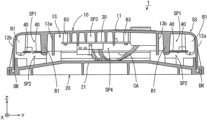
As shown in FIG. 1 , the communication unit 1 includes a casing 10, a lid 20, a circuit board 30, and an antenna 40. The casing 10 and the lid 20 define the housing 50. The circuit board 30 and the antenna 40 are stored in the housing 50. The casing 10 includes a lower opening. The lower opening of the casing 10 is closed by the lid 20. An inner space IS is defined by the casing 10 and the lid 20. A wiring cable CA is connected to the circuit board 30.
As shown in FIGS. 2 and 3 , the casing 10 includes a rectangular upper plate 11 (see FIG. 3 ) and four outer walls 12 a to 12 d. In the present example, the upper plate 11 includes a pair of short sides extending in the X direction and a pair of long sides extending in the Y direction. A pair of outer walls 12 a, 12 b project downwardly from the two short sides of the upper plate 11. The other pair of outer walls 12 c, 12 d project downwardly from the two long sides of the upper plate 11.
As shown in FIG. 2 , in the region surrounded by the outer walls 12 a to 12 d, four inner walls 13 a to 13 d project downwardly from the lower surface of the upper plate 11. A pair of inner walls 13 a, 13 b extend in the X direction, and the other pair of inner walls 13 c, 13 d extend in the Y direction. The positions of the lower ends of the inner walls 13 a to 13 d are higher than the positions of the lower ends of the outer walls 12 a to 12 d. In FIG. 2 , a dotted pattern is applied to the inner walls 13 a to 13 d.
A plurality of ribs R1 and a plurality of bosses B1, B2, B3 are provided to project downwardly from the lower surface of the upper plate 11. The detailed arrangement of the plurality of ribs R1 and the plurality of bosses B1, B2, B3 will be described below. Attachment portions 121 a, 121 b project, respectively, outwardly and horizontally from the lower ends of the pair of outer walls 12 a, 12 b. A plurality of attachment holes 122 are provided in each of the attachment portions 121 a, 121 b. The casing 10 is integrally made of a plastic material.
The lid 20 includes a lower plate 21. A plurality of ribs R2 for reinforcement are provided in a grid pattern at the lower surface of the lower plate 21. A plurality of cutouts n1 are provided in an outer peripheral edge of the lower plate 21. The lid 20 is integrally made of a plastic material similarly to the casing 10.
As shown in FIG. 3 , a take-out hole 111 for the wiring cable CA is provided in the portion between the outer wall 12 d and the inner wall 13 d in the upper plate 11 of the casing 10. The upper surface of the lower plate 21 of the lid 20 is inclined outwardly and downwardly. More specifically, the lower plate 21 includes a rectangular horizontal portion 211 and four trapezoidal inclined portions 212 a to 212 d. The inclined portions 212 a to 212 d extend, respectively, obliquely and downwardly from the four sides of the horizontal portion 211. Thus, in a case where water intrudes into the inner space IS of the housing 50, the water adhering to the upper surface of the lower plate 21 of the housing 50 is likely to flow downwardly.
A plurality of projection walls 213 project upwardly and extending along the edge of the upper surface of the lid 20. A cutout n2 for drainage is provided between adjacent projection walls 213. Further, a plurality (four in the present example) of bases 215 are provided on the upper surface of the lid 20. A though hole is provided in each base 215. The plurality of bases 215 are attached to bosses B2, described below, for attaching the lid of the casing 10 with screws.
FIG. 4 is a bottom view of the casing 10 to which the circuit board 30 or the antenna 40 is not attached. As shown in detail in FIG. 4 , in the region between the outer walls 12 a to 12 d and the inner walls 13 a to 13 d, the plurality of ribs R1 for supporting the antenna and for reinforcement extend in the X and Y directions. The plurality of ribs R1 are an example of a supporter or a plurality of projections. The detailed shape of the ribs R1 will be described below.
Further, in the region between the outer walls 12 a to 12 d and the inner walls 13 a to 13 d, a plurality of bosses B1 for holding the antenna and a plurality (four in the present example) of bosses B2 for attaching the lid are provided. Further, in the region surrounded by the inner walls 13 a to 13 d, a plurality of bosses B3 for holding the circuit board are provided. A screw hole is provided in each of the bosses B1, B2, B3. Each boss B1 is integral with the rib R1. Out of two bosses B1 located at two adjacent ribs R1, one boss B1 is provided at an inner position (a position closer to the inner walls 13 a to 13 d), and the other boss B1 is provided at an outer position (a position closer to the outer walls 12 a to 12 d).
FIG. 5 is a bottom view of the casing 10 to which the circuit board 30 and the antenna 40 are attached. In the region between the outer walls 12 a to 12 d and the inner walls 13 a to 13 d, the antenna 40 is provided on the plurality of ribs R1 and extends in a substantially rectangular shape. In the present example, one antenna 40 has the shape of a continuous double rectangle. The antenna 40 is fixed to the plurality of bosses B1 of FIG. 4 by screws S1. Both ends of the antenna 40 are electrically connected to the circuit board 30.
In the region surrounded by the inner walls 13 a to 13 d, the circuit board 30 is fixed to the plurality of bosses B3 of FIG. 4 by screws S2. The circuit board 30 includes a plurality of wiring traces. A plurality of electronic components 31 are mounted on the upper and lower surfaces of the circuit board 30. Thus, a communication circuit that communicates with a RFID (Radio Frequency Identification) tag 200 (FIG. 11 ), described below, is provided.
The inner walls 13 a to 13 d surround the entire periphery of the circuit board 30 in a plan view. As shown in FIGS. 1 and 2 , the inner walls 13 a to 13 d project to positions farther downward than the circuit board 30 in a side view.
As shown in FIG. 1 , a first space SP1 is provided between the antenna 40 and the upper plate 11 of the casing 10, and a second space SP2 is provided between the antenna 40 and the lower plate 21 of the lid 20. In this case, the antenna 40 is suspended from the upper plate 11 of the housing 50 in the inner space IS.
In the present preferred embodiment, a third space SP3 is provided between the circuit board 30 and the upper plate 11, and a fourth space SP4 is provided between the circuit board 30 and the lower plate 21. The circuit board 30 is located at a position higher than the antenna 40.
FIG. 6 is a schematic diagram showing the configuration of ribs for supporting the antenna. In FIG. 6 , a front view of two ribs R1 that are adjacent to each other in the X or Y direction are vertically oriented and shown. One of the two adjacent ribs R1 is referred to as a rib R1 a, and the other rib is referred to as a rib R1 b. Further, the boss B1 integral with the rib R1 a is referred to as a boss B1 a, and the boss B1 integral with the rib R1 b is referred to as a boss B1 b. Further, the screw S1 attached to the boss B1 a is referred to as a screw S1 a, and the screw S1 attached to the boss B1 b is referred to as a screw S1 b. The ribs R1 a, R1 b are an example of the first and second projections.
In FIG. 6 , the position closer to the inner walls 13 a to 13 d is referred to as inward, and the position closer to the outer walls 12 a to 12 d is referred to as outward. A protrusion Pa that protrudes downwardly is provided at the center of the lower end of the one rib R1 a. A concave portion Na is provided in an inner portion at the lower end of the rib R1 a. The boss B1 a is located at the outer end of the rib R1 a. A protrusion Pb protruding downwardly is provided at the center of the lower end of the other rib R1 b. A concave portion Nb is provided in an outer portion at the lower end of the rib R1 b. The boss B1 b is located at the inner end of the rib R1 b.
The antenna 40 includes a first antenna portion 41 and a second antenna portion 42 which are adjacent to each other in the X or Y direction. The first antenna portion 41 is located outwardly of the second antenna portion 42.
The first antenna portion 41 is supported at the outer portion of the lower end of the one rib R1 a between the protrusion Pa of the rib R1 a and the boss B1 a, and is connected to the boss B1 a by the screw S1 a. Further, the first antenna portion 41 is spaced apart from the other rib R1 b in the concave portion Nb of the rib R1 b.
The second antenna portion 42 is supported at the inner portion of the lower end of the other rib R1 b between the protrusion Pb of the rib R1 b and the boss B1 b, and is connected to the boss B1 b by the screw S1 b. Further, the second antenna portion 42 is spaced apart from the one rib R1 a in the concave portion Na of the rib R1 a.
In the present example, cutouts n4 are provided at the lower ends of the bosses B1 a, B1 b to extend along the side surfaces of the first and second antenna portions 41, 42. The first and second antenna portions 41, 42 are fixed between the cutouts n4 of the bosses B1 a, B1 b and the screws S1 a, S1 b.
With such a configuration of the ribs R1 a, R1 b, the supporting portion of the rib R1 a with respect to the first antenna portion 41 and the supporting portion of the rib R1 b with respect to the second antenna portion 42 are discontinuous. In this case, bridging between the ribs R1 a, R1 b by water is significantly reduced or prevented. Thus, water staying on the surfaces of the first and second antenna portions 41, 42 and between the first and second antenna portions 41, 42 is significantly reduced or prevented.
FIG. 7 is a plan view of the lid 20. A groove is provided as a drainage path DR to extend along the outer peripheral edge of the upper surface of the lower plate 21 of the lid 20. FIG. 8 is a cross-sectional view taken along the line A-A of FIGS. 4 and 7 , FIG. 9 is a cross-sectional view taken along the line B-B of FIGS. 4 and 7 , and FIG. 10 is a cross-sectional view taken along the line C-C of FIGS. 4 and 7 .
As shown in FIGS. 8 to 10 , the lower end of the outer wall 12 a is bent horizontally and outwardly and then further bent downwardly. The structure of the lower ends of the outer walls 12 b to 12 d is similar to the lower end of the outer wall 12 a. Thus, a first bending structure FS1 is provided in the lower edges of the outer walls 12 a to 12 d.
The outer periphery of the lid 20 is bent downwardly, bent horizontally and outwardly, and further bent upwardly. Thus, a second bending structure FS2 is provided in the outer edge of the lid 20. In this case, the lower edges of the outer walls 12 a to 12 d are fitted to the outer edge of the lid 20, and a labyrinth structure is defined by the first bending structure FS1 of the casing 10 and the second bending structure FS2 of the lid 20. As a result, water intrusion into the inner space IS of the housing 50 is reduced even with the casing 10 and the lid 20 not having a completely sealed structure.
Further, the drainage path DR is defined by the second bending structure FS2. The drainage path DR is provided in the outer edge at the lower end of the housing 50. As shown in FIG. 8 , the drainage path DR communicates with the inner space IS of the housing 50 through the cutout n2 of the lid 20. Thus, the water that has intruded into the inner space IS is guided to the drainage path DR as indicated by the arrow W1. As shown in FIG. 9 , as for the portions except for the cutouts n1, n2, the upper portion of the drainage path DR is closed by the outer wall 12 a (and the outer walls 12 b to 12 d). As shown in FIG. 10 , a drainage hole h1 that communicates with the space below is defined by the cutout n1 of the lid 20 and the outer wall 12 a (and the outer walls 12 b to 12 d) of the casing 10. The water that has been guided to the drainage path DR is drained downwardly through the drainage hole h1 as indicated by the arrow W2. A drainage hole h2 that communicates with the outer space above is provided in the outer wall 12 a (and the outer walls 12 b to 12 d). In this example, each drainage hole h2 is located above the drainage hole h1. The drainage hole h1 is an example of a first hole, and the drainage hole h2 is an example of a second hole.
In this case, water that has been guided from the inner space IS of the housing 50 to the drainage path DR drains downwardly from the housing 50 through the drainage hole h1. Meanwhile, water that has splashed and entered into the drainage path DR from below the housing 50 through the drainage hole h1 is directly drained through the upper drainage hole h2 as indicated by the arrow W3. Thus, water is unlikely to intrude into the inner space IS of the housing 50 through the drainage path DR.
(2) Vehicle Including Communication Unit 1
Next, a golf cart will be described as an example of the vehicle including the communication unit 1. FIG. 11 is an external side view of the golf cart including the communication unit 1 of FIG. 1 . FIG. 12 is a plan view showing the position of the communication unit in the golf cart. As shown in FIG. 11 , the golf cart 100 includes a vehicle body 110, a pair of steering wheels 120, which are front wheels, and a pair of rear wheels 130. The vehicle body 110 includes a main frame MF. A floor member FL is provided above the main frame MF.
A front seat 140 is provided substantially in the center portion on the floor member FL, and a rear seat 150 is provided in a rear portion on the floor member FL. A handle 160 is provided forwardly of the front seat 140. A passenger who is seated on the front seat 140 operates the handle 160, such that the direction of the steering wheels 120 is adjusted, and the golf cart 100 is steered. An RFID tag 200 is buried in the ground G.
The uppermost portion of the communication unit 1 is located at a position farther downward than the lower surface of the floor member FL, and the lowermost portion of the communication unit 1 is located at a position farther upward than the lower end of the main frame MF. That is, the height H1 from the ground G to the uppermost portion of the communication unit 1 is smaller than the height Hf from the ground G to the floor member FL. Further, the height H2 from the ground G to the lowermost portion of the communication unit 1 is larger than the height Hm from the ground G to the lower end of the main frame MF.
As shown in FIG. 12 , the main frame MF includes the left and right frame members Fa, Fb. The communication unit 1 is located between the left and right frame members Fa, Fb. In the present example, the communication unit 1 is located on the center axis CL between the left and right frame members Fa, Fb.
With such an arrangement, the distance between the antenna 40 and the RFID tag 200 in the ground G is reduced. Thus, a good communication state between the communication unit 1 and the RFID tag 200 is maintained. Further, because the communication unit 1 is located at a position farther upward than the lowermost end of the main frame MF, contact of the communication unit 1 with the ground G during traveling of the golf cart 100 is avoided. Further, when the golf cart 100 is transported by a forklift, forks do not come into contact with the communication unit 1. Thus, damage to the communication unit 1 is significantly reduced or prevented.
Further, the antenna 40 of the communication unit 1 is located at a position closer to the steering wheels 120 than to the rear wheels 130. Thus, a change in distance between the antenna 40 and the RFID tag 200 caused by a turning radius difference between inner wheels and a turning radius difference between outer wheels depending on a steering angle of the steering wheels 120 is significantly reduced or prevented. As a result, stable communication between the communication unit 1 and the RFID tag 200 is maintained.
(3) Effects of the Preferred Embodiments
FIG. 13 is a schematic diagram showing the communication unit 1 when water has intruded into the communication unit 1. In a case where the golf cart 100 travels through a puddle, for example, the communication unit 1 may tilt, and water may temporarily intrude into the inner space IS of the housing 50. Even in such a case, because the circuit board 30 is surrounded by the upper plate 11 and the inner walls 13 a to 13 d in the communication unit 1 according to the present preferred embodiment, the intruding water is unlikely to reach the circuit board 30. In the example of FIG. 13 , the water level in the inner space IS of the housing 50 is lower than the water level outside of the housing 50, and the water level in the space surrounded by the upper plate 11 and the inner walls 13 a to 13 d is lower than the water level outside of the inner walls 13 a to 13 d. Thus, adhesion of water to the circuit board 30 is significantly reduced or prevented.
Further, in the communication unit 1 according to the present preferred embodiment, the circuit board 30 is not sealed with resin, and the housing 50 does not require a completely sealed structure. Thus, the manufacturing cost is reduced, and the manufacturing process is not complicated. Therefore, even in a case where the communication unit 1 is located at a position close to the ground G, the influence of water is reduced without the requirement of a completely sealed structure. Further, the communication unit 1 is manufactured easily at low cost. Further, the electronic components 31 on the circuit board 30 are easily adjusted after the communication unit 1 is manufactured.
In the present preferred embodiment, because the labyrinth structure is provided by the first bending structure FS1 of the casing 10 and the second bending structure FS2 of the lid 20, water intrusion into the inner space IS of the housing 50 is reduced even with the casing 10 and the lid 20 not having a completely sealed structure.
Further, because the drainage path DR is provided in the outer edge at the lower end of the housing 50, even in a case where water intrudes into the inner space IS of the housing 50, the water is moved to the lower portion of the inner space IS by gravity and drained through the drainage path DR of the housing 50. Thus, water staying in the inner space IS of the housing 50 is significantly reduced or prevented.
Further, since the upper surface of the lower plate 21 of the lid 20 is inclined outwardly and downwardly, in a case where water intrudes into the inner space IS of the housing 50, the water adhering to the upper surface of the lower plate 21 of the housing 50 is likely to flow downwardly to the drainage path DR outside. Thus, water staying in the inner space IS of the housing 50 is significantly reduced or prevented.
The degradation of performance due to temporary adhesion of water to the antenna 40 is small as compared to adhesion of water to the circuit board 30. In the present preferred embodiment, because the circuit board 30 is located in the space inside of the inner walls 13 a to 13 d, and the antenna 40 is located in the space between the inner walls 13 a to 13 d and the outer walls 12 a to 12 d, the space inside of the inner walls 13 a to 13 d surrounding the circuit board 30 is reduced. Thus, the distance between the inner walls 13 a to 13 d and the outer walls 12 a to 12 d is increased. As a result, the circuit board 30 is protected from the water that has intruded into the inner space IS of the housing 50.
Further, because the antenna 40 is suspended from the upper plate 11 of the housing 50 in the inner space IS, the water adhering to the antenna 40 is likely to drop, and water staying on the surface of the antenna 40 is significantly reduced or prevented. As a result, significant degradation of performance of the antenna 40 is significantly reduced or prevented.
In the present preferred embodiment, the circuit board 30 is located at a position higher than the antenna 40. In this case, the likelihood of the circuit board 30 coming into contact with water is reduced while the distance between the antenna 40 and the ground G is reduced.
(4) Other Preferred Embodiments
FIG. 14 is a cross-sectional view of a communication unit 1 according to another preferred embodiment of the present invention. The communication unit 1 of FIG. 14 differs from the communication unit 1 of FIG. 1 in that an intermediate wall 14 is provided between the outer walls 12 a to 12 d and the inner walls 13 a to 13 d of the casing 10. The intermediate wall 14 surrounds the entire periphery of the inner walls 13 a to 13 d in a plan view and projects from the lower surface of the upper plate 11 to a position farther downward than the lower ends of the inner walls 13 a to 13 d in a side view. The casing 10 includes a lower opening (hereinafter referred to as an inner opening OP1) surrounded by the lower ends of the inner walls 13 a to 13 d, a lower opening (hereinafter referred to as an intermediate opening OP2) surrounded by the lower end of the intermediate wall 14, and a lower opening (hereinafter referred to as an outer opening OP3) surrounded by the lower ends of the outer walls 12 a to 12 d.
The outer edge of the intermediate opening OP2 is located at the lower end of the intermediate wall 14. The outer edge of the outer opening OP3 is located at the lower ends of the outer walls 12 a to 12 d. In the communication unit 1 of FIG. 1 , the outer opening OP3 is closed by the lower plate 21 of the lid 20. In contrast, in the communication unit 1 of FIG. 14 , the intermediate opening OP2 is closed by the lower plate 21 of the lid 20. In the region outside of the intermediate wall 14, holes h3 may be provided in the lower plate 21. Because the circuit board 30 is also surrounded by the upper plate 11 and the inner walls 13 a to 13 d in the configuration of FIG. 14 , the water that has intruded into the inner space IS of the housing 50 is unlikely to reach the circuit board 30. The antenna 40 may be located in the space between the intermediate wall 14 and the inner walls 13 a to 13 d.
While the antenna 40 is located in the space between the outer walls 12 a to 12 d and the inner walls 13 a to 13 d in the above-described preferred embodiments, the present invention is not limited to this. The antenna 40 may be located in the space surrounded by the inner walls 13 a to 13 d. While the antenna 40 surrounds the inner walls 13 a to 13 d in the above-described preferred embodiments, the present invention is not limited to this. The antenna 40 may be located in a portion of the region between the outer walls 12 a to 12 d and the inner walls 13 a to 13 d.
While the circuit board 30 is located at a position higher than the antenna 40 in the inner space IS of the housing 50 in the above-described preferred embodiments, the present invention is not limited to this. The antenna 40 may be located at a position as high as the circuit board 30 or at a position higher than the circuit board 30.
While the casing 10 includes the upper plate 11 and the outer walls 12 a to 12 d, and the lid 20 includes the lower plate 21 in the above-described preferred embodiments, the present invention is not limited to this. A lid may include the upper plate 11, and a casing may include the lower plate 21 and the outer walls 12 a to 12 d.
While the drainage path DR is provided in an edge at the lower end of the housing 50 in the above-described preferred embodiments, the present invention is not limited to this. For example, the drainage path DR may be provided in a center portion of the lower plate 21 of the housing 50. Alternatively, the drainage path DR does not have to be provided.
While the labyrinth structure is defined by the first bending structure FS1 of the casing 10 and the second bending structure FS2 of the lid 20 in the above-described preferred embodiments, the present invention is not limited to this. In a case where an amount of water that intrudes from the connection between the casing 10 and the lid 20 is small, the labyrinth structure does not have to be provided.
While the upper surface of the lower plate 21 of the lid 20 is inclined outwardly and downwardly in the above-described preferred embodiments, the present invention is not limited to this. The upper surface of the lower plate 21 of the lid 20 may be a horizontal plane. Alternatively, the upper surface of the lower plate 21 of the lid 20 may be inclined inwardly and downwardly. In that case, a drainage path or a drainage hole may be provided in the center portion of the lower plate.
While the steering wheels 120 of the golf cart 100 are the front wheels in the above-described preferred embodiments, the present invention is not limited to this. The rear wheels may be steering wheels. In that case, the antenna 40 of the communication unit 1 is preferably located at a position closer to the steering wheels than to the front wheels. Further, the above-described arrangements of the communication unit 1 in the golf cart 100 is one example, and the communication unit 1 may be located in another portion of the golf cart 100. Further, the communication unit 1 is not limited to the golf cart 100 but may be provided in another vehicle such as a four-wheeled vehicle or an automobile.
While preferred embodiments of the present invention have been described above, it is to be understood that variations and modifications will be apparent to those skilled in the art without departing from the scope and spirit of the present invention. The scope of the present invention, therefore, is to be determined solely by the following claims.

Claims (13)

The invention claimed is:
1. A communication unit comprising:
a circuit board on which a communication circuit is provided;
an antenna connected to the communication circuit; and
a housing that stores the circuit board and the antenna; wherein
the housing includes an upper plate, a lower plate, and an outer wall, the upper plate is located above the lower plate, and an inner space is defined by the upper plate, the lower plate, and the outer wall; and
an inner wall is provided in the inner space and surrounds an entire periphery of the circuit board in a plan view and projects from a lower surface of the upper plate to a position farther downward than the circuit board in a side view.
2. The communication unit according to claim 1, wherein
the housing further includes a supporter that supports the antenna in the inner space such that a first space is provided between the antenna and the lower surface of the upper plate and a second space is provided between the antenna and an upper surface of the lower plate;
the supporter includes a plurality of projections that project downwardly from the lower surface of the upper plate; and
the antenna is supported by the plurality of projections in the inner space.
3. The communication unit according to claim 2, wherein
the antenna includes a first antenna portion and a second antenna portion that are adjacent but spaced apart from each other;
the plurality of projections include a first projection that supports the first antenna portion and a second projection that supports the second antenna portion; and
the plurality of projections are located such that a supporting portion of the first projection with respect to the first antenna portion and a supporting portion of the second projection with respect to the second antenna portion are discontinuous.
4. The communication unit according to claim 1, wherein
the housing includes a casing including the upper plate and the outer wall and includes a lower opening; and
a lid including the lower plate and that closes the lower opening of the casing;
an outer edge of the lower opening is located outside of a region surrounded by a lower end of the inner wall in the plan view; and
the inner space is defined by the outer wall of the casing and the lid being connected to each other.
5. The communication unit according to claim 4, wherein
the outer edge of the lower opening is located at a lower end of the outer wall.
6. The communication unit according to claim 4, wherein
a lower edge of the outer wall of the casing includes a first bending structure;
an outer edge of the lid includes a second bending structure; and
the lower edge of the outer wall and the outer edge of the lid are connected to each other, and a labyrinth structure is defined by the first bending structure and the second bending structure.
7. The communication unit according to claim 1, wherein
a drainage path is provided in an edge at a lower end of the housing.
8. The communication unit according to claim 7, wherein
a first hole is provided in the housing and communicates the drainage path with a space below the housing; and
a second hole is provided in the housing and communicates the drainage path with a space outside of the housing above the first hole.
9. The communication unit according to claim 1, wherein
an upper surface of the lower plate of the housing is inclined outwardly and downwardly.
10. The communication unit according to claim 1, wherein
the antenna is located between the outer wall and the inner wall.
11. The communication unit according to claim 1, wherein
the circuit board is located at a position higher than the antenna.
12. A vehicle comprising:
a main frame including a pair of left and right frame portions;
a floor located at a position farther upward than the main frame;
a steering wheel to support the main frame on the ground in a vehicle front-and-rear direction; and
the communication unit according to claim 1; wherein
the communication unit is located between the pair of left and right frame portions in a plan view of the vehicle; and
an uppermost portion of the communication unit is located at a position farther downward than a lower surface of the floor, and a lowermost portion of the communication unit is located at a position farther upward than a lower end of the main frame.
13. The vehicle according to claim 12, further comprising:
a wheel provided at a position farther forward or rearward than the steering wheel in a side view of the vehicle; wherein
the antenna of the communication unit is located at a position closer to the steering wheel than to the wheel in the side view of the vehicle.
US16/966,030 2018-02-15 2018-10-23 Communication unit and vehicle Active 2040-08-07 US11731568B2 (en)

Applications Claiming Priority (3)

Application Number Priority Date Filing Date Title
JP2018025346A JP6582073B2 (en) 2018-02-15 2018-02-15 Communication unit and vehicle
JP2018-025346 2018-02-15
PCT/JP2018/039390 WO2019159437A1 (en) 2018-02-15 2018-10-23 Communication unit and vehicle

Publications (2)

Publication Number Publication Date
US20200353875A1 US20200353875A1 (en) 2020-11-12
US11731568B2 true US11731568B2 (en) 2023-08-22

Family

ID=67619199

Family Applications (1)

Application Number Title Priority Date Filing Date
US16/966,030 Active 2040-08-07 US11731568B2 (en) 2018-02-15 2018-10-23 Communication unit and vehicle

Country Status (6)

Country Link
US (1) US11731568B2 (en)
JP (1) JP6582073B2 (en)
KR (1) KR102572493B1 (en)
CN (1) CN111713026B (en)
PH (1) PH12020551252A1 (en)
WO (1) WO2019159437A1 (en)

Families Citing this family (3)

* Cited by examiner, † Cited by third party
Publication number Priority date Publication date Assignee Title
JP7342685B2 (en) * 2019-12-20 2023-09-12 三菱自動車工業株式会社 Vehicle luggage compartment structure
EP4011708B1 (en) * 2020-12-10 2025-02-26 Volvo Truck Corporation Motor vehicle with a box for electronic components extending below the floor of the cabin
CN121336320A (en) * 2023-07-19 2026-01-13 Lg电子株式会社 Antenna assembly mounted on a vehicle

Citations (11)

* Cited by examiner, † Cited by third party
Publication number Priority date Publication date Assignee Title
JPH11312998A (en) 1998-04-28 1999-11-09 Kyocera Corp Portable radio
JP2002225640A (en) 2001-01-30 2002-08-14 Tokai Rika Co Ltd Communicating device for vehicle
JP2005217075A (en) 2004-01-28 2005-08-11 Denso Corp Structure for fitting printed board
US20050227542A1 (en) * 2004-04-12 2005-10-13 Autonetworks Technologies, Ltd. Electrical connection box
JP2007300198A (en) 2006-04-27 2007-11-15 Tatsuno Matsushita Denko Kk Sealing structure of electric equipment
JP3161101U (en) 2010-05-07 2010-07-22 株式会社慶洋エンジニアリング In-vehicle GPS antenna device
JP2011035822A (en) 2009-08-05 2011-02-17 Panasonic Corp Portable wireless device
US20120062428A1 (en) 2009-05-28 2012-03-15 Panasonic Corporation Portable radio
JP2012074524A (en) 2010-09-28 2012-04-12 Kyocera Corp Electronic apparatus
US20130070433A1 (en) 2011-09-15 2013-03-21 Tadaaki Onishi In-vehicle electronic device
US20180013230A1 (en) 2016-07-06 2018-01-11 Sumitomo Wiring Systems, Ltd. Drainage structure for electrical connection box

Patent Citations (16)

* Cited by examiner, † Cited by third party
Publication number Priority date Publication date Assignee Title
JPH11312998A (en) 1998-04-28 1999-11-09 Kyocera Corp Portable radio
JP2002225640A (en) 2001-01-30 2002-08-14 Tokai Rika Co Ltd Communicating device for vehicle
JP2005217075A (en) 2004-01-28 2005-08-11 Denso Corp Structure for fitting printed board
US20050227542A1 (en) * 2004-04-12 2005-10-13 Autonetworks Technologies, Ltd. Electrical connection box
CN1684329A (en) 2004-04-12 2005-10-19 株式会社自动网络技术研究所 Electrical connection box
JP2007300198A (en) 2006-04-27 2007-11-15 Tatsuno Matsushita Denko Kk Sealing structure of electric equipment
US20120062428A1 (en) 2009-05-28 2012-03-15 Panasonic Corporation Portable radio
CN102428605A (en) 2009-05-28 2012-04-25 松下电器产业株式会社 portable wireless device
JP2011035822A (en) 2009-08-05 2011-02-17 Panasonic Corp Portable wireless device
US20120127043A1 (en) * 2009-08-05 2012-05-24 Panasonic Corporation Portable radio
JP3161101U (en) 2010-05-07 2010-07-22 株式会社慶洋エンジニアリング In-vehicle GPS antenna device
JP2012074524A (en) 2010-09-28 2012-04-12 Kyocera Corp Electronic apparatus
US20130070433A1 (en) 2011-09-15 2013-03-21 Tadaaki Onishi In-vehicle electronic device
CN103000984A (en) 2011-09-15 2013-03-27 阿尔卑斯电气株式会社 In-vehicle electronic device
US20180013230A1 (en) 2016-07-06 2018-01-11 Sumitomo Wiring Systems, Ltd. Drainage structure for electrical connection box
CN107591755A (en) 2016-07-06 2018-01-16 住友电装株式会社 The discharge structure of electric connection box

Non-Patent Citations (4)

* Cited by examiner, † Cited by third party
Title
First Office Action in KR10-2020-7021633, dated Jan. 19, 2023, 5 pages.
Official Communication issued in corresponding Chinese Patent Application No. 201880089420.8, dated Dec. 17, 2021.
Official Communication issued in corresponding Chinese Patent Application No. 201880089420.8, dated Jun. 1, 2021.
Official Communication issued in International Patent Application No. PCT/JP2018/039390, dated Dec. 25, 2018.

Also Published As

Publication number Publication date
KR20200119240A (en) 2020-10-19
JP2019145872A (en) 2019-08-29
PH12020551252A1 (en) 2021-04-19
CN111713026B (en) 2022-01-25
KR102572493B1 (en) 2023-08-30
US20200353875A1 (en) 2020-11-12
JP6582073B2 (en) 2019-09-25
CN111713026A (en) 2020-09-25
WO2019159437A1 (en) 2019-08-22

Similar Documents

Publication Publication Date Title
US11731568B2 (en) Communication unit and vehicle
CN203460815U (en) Cell box
US9374916B2 (en) Electrical junction box
KR102145985B1 (en) Roof Mount Imager Module
CN106043144A (en) Arrangement structure for vicinity information detection sensor
US20180055172A1 (en) Waterproof enclosure
US5823819A (en) Electric junction box
CN111284420A (en) Camera Mounting Structure
JP6604519B2 (en) Board unit
US20170086318A1 (en) Electronic apparatus
JP5618410B2 (en) Lead-acid battery for vehicles
US7075006B2 (en) Electrical junction box
KR20200136584A (en) Radar apparatus moungtinh assembly
JP2021057991A (en) Electric connection box
US10462914B2 (en) Cover structure and electric connection box
JP3956779B2 (en) Electrical junction box
JP4542493B2 (en) Electrical junction box
CN220895697U (en) Battery pack
CN116176237A (en) Tailgate assembly for vehicle and vehicle
CN211424807U (en) freezer
US20250263130A1 (en) Vehicle lower part structure
KR20210085567A (en) UWB module assembly with shock absorbing structure and manufacturing method thereof
JP7473588B2 (en) Electrical Junction Box
JP6996986B2 (en) Housing and electrical junction box
JP2012023153A (en) Substrate fitting structure

Legal Events

Date Code Title Description
AS Assignment

Owner name: YAMAHA MOTOR POWER PRODUCTS KABUSHIKI KAISHA, JAPAN

Free format text: ASSIGNMENT OF ASSIGNORS INTEREST;ASSIGNOR:OMURA, YUICHI;REEL/FRAME:053350/0148

Effective date: 20200722

FEPP Fee payment procedure

Free format text: ENTITY STATUS SET TO UNDISCOUNTED (ORIGINAL EVENT CODE: BIG.); ENTITY STATUS OF PATENT OWNER: LARGE ENTITY

STPP Information on status: patent application and granting procedure in general

Free format text: DOCKETED NEW CASE - READY FOR EXAMINATION

STPP Information on status: patent application and granting procedure in general

Free format text: PUBLICATIONS -- ISSUE FEE PAYMENT RECEIVED

STCF Information on status: patent grant

Free format text: PATENTED CASE