US11729626B2 - Method of operating spectrum sharing system interoperating with distributed antenna system - Google Patents
Method of operating spectrum sharing system interoperating with distributed antenna system Download PDFInfo
- Publication number
- US11729626B2 US11729626B2 US16/421,939 US201916421939A US11729626B2 US 11729626 B2 US11729626 B2 US 11729626B2 US 201916421939 A US201916421939 A US 201916421939A US 11729626 B2 US11729626 B2 US 11729626B2
- Authority
- US
- United States
- Prior art keywords
- radio service
- service device
- das
- radio
- information
- Prior art date
- Legal status (The legal status is an assumption and is not a legal conclusion. Google has not performed a legal analysis and makes no representation as to the accuracy of the status listed.)
- Active
Links
- 238000001228 spectrum Methods 0.000 title claims abstract description 78
- 238000000034 method Methods 0.000 title claims abstract description 66
- 238000005516 engineering process Methods 0.000 claims description 40
- 230000008569 process Effects 0.000 claims description 10
- 230000000737 periodic effect Effects 0.000 claims description 5
- 238000004891 communication Methods 0.000 description 56
- 238000012545 processing Methods 0.000 description 40
- 238000010586 diagram Methods 0.000 description 10
- 239000013307 optical fiber Substances 0.000 description 10
- 230000006870 function Effects 0.000 description 6
- 230000005540 biological transmission Effects 0.000 description 3
- 230000003321 amplification Effects 0.000 description 2
- 230000008901 benefit Effects 0.000 description 2
- 230000000694 effects Effects 0.000 description 2
- 238000001914 filtration Methods 0.000 description 2
- 238000009434 installation Methods 0.000 description 2
- 238000007726 management method Methods 0.000 description 2
- 238000010295 mobile communication Methods 0.000 description 2
- 238000012986 modification Methods 0.000 description 2
- 230000004048 modification Effects 0.000 description 2
- 230000007935 neutral effect Effects 0.000 description 2
- 238000003199 nucleic acid amplification method Methods 0.000 description 2
- 101100014709 Drosophila melanogaster wisp gene Proteins 0.000 description 1
- 230000006978 adaptation Effects 0.000 description 1
- 238000013475 authorization Methods 0.000 description 1
- 238000005259 measurement Methods 0.000 description 1
- 238000005457 optimization Methods 0.000 description 1
- 230000001151 other effect Effects 0.000 description 1
- 238000013468 resource allocation Methods 0.000 description 1
- 230000001502 supplementing effect Effects 0.000 description 1
- 238000012546 transfer Methods 0.000 description 1
Images


Classifications
-
- H—ELECTRICITY
- H04—ELECTRIC COMMUNICATION TECHNIQUE
- H04W—WIRELESS COMMUNICATION NETWORKS
- H04W16/00—Network planning, e.g. coverage or traffic planning tools; Network deployment, e.g. resource partitioning or cells structures
- H04W16/14—Spectrum sharing arrangements between different networks
-
- H—ELECTRICITY
- H04—ELECTRIC COMMUNICATION TECHNIQUE
- H04W—WIRELESS COMMUNICATION NETWORKS
- H04W4/00—Services specially adapted for wireless communication networks; Facilities therefor
- H04W4/02—Services making use of location information
- H04W4/025—Services making use of location information using location based information parameters
-
- H—ELECTRICITY
- H04—ELECTRIC COMMUNICATION TECHNIQUE
- H04W—WIRELESS COMMUNICATION NETWORKS
- H04W72/00—Local resource management
- H04W72/50—Allocation or scheduling criteria for wireless resources
- H04W72/51—Allocation or scheduling criteria for wireless resources based on terminal or device properties
-
- H—ELECTRICITY
- H04—ELECTRIC COMMUNICATION TECHNIQUE
- H04W—WIRELESS COMMUNICATION NETWORKS
- H04W76/00—Connection management
- H04W76/10—Connection setup
- H04W76/11—Allocation or use of connection identifiers
-
- H—ELECTRICITY
- H04—ELECTRIC COMMUNICATION TECHNIQUE
- H04W—WIRELESS COMMUNICATION NETWORKS
- H04W76/00—Connection management
- H04W76/10—Connection setup
- H04W76/15—Setup of multiple wireless link connections
-
- H—ELECTRICITY
- H04—ELECTRIC COMMUNICATION TECHNIQUE
- H04W—WIRELESS COMMUNICATION NETWORKS
- H04W88/00—Devices specially adapted for wireless communication networks, e.g. terminals, base stations or access point devices
- H04W88/08—Access point devices
- H04W88/085—Access point devices with remote components
-
- H—ELECTRICITY
- H04—ELECTRIC COMMUNICATION TECHNIQUE
- H04W—WIRELESS COMMUNICATION NETWORKS
- H04W88/00—Devices specially adapted for wireless communication networks, e.g. terminals, base stations or access point devices
- H04W88/18—Service support devices; Network management devices
- H04W88/182—Network node acting on behalf of an other network entity, e.g. proxy
Definitions
- One or more embodiments relate to a spectrum sharing system. More particularly, the disclosure relates to a method of operating a spectrum sharing system comprising a distributed antenna system.
- radio station management and a service system based on spectrum sharing is being actively discussed in order to efficiently utilize limited radio resources (e.g., a bandwidth and transmission power) mainly in major advanced countries.
- limited radio resources e.g., a bandwidth and transmission power
- CBRS citizens Broadband Radio Service
- the United States has announced the introduction of citizens Broadband Radio Service (CBRS), which is an urban spectrum sharing service in the 3.5 GHz band
- CBRS citizens Broadband Radio Service
- the United Kingdom has announced the introduction of spectrum co-use for the 3.8 GHz to 4.2 GHz bands based on the Framework for Spectrum Sharing.
- Such a spectrum sharing service is expected not only to be applied in the existing specific service field but also to provide a sufficient advantage for substituting and converging various services as well as supplementing a mobile communication service such as 5G.
- a distributed antenna system is a system composed of spatially separated antenna nodes (e.g., remote units) connected to a common node (e.g., a head-end unit) through a transmission medium such as optical fiber, wired Ethernet, and the like, or a transmission network.
- a transmission medium such as optical fiber, wired Ethernet, and the like, or a transmission network.
- the DAS is installed in an area where radio signals are not received or where radio signals are weak, such as inside buildings, underground buildings, subways, tunnels, apartment complexes in a residential area, stadiums, and the like to extend coverage of a base station by providing communication services to even a shadow area where signals of the base station are difficult to reach.
- the DAS is closely related to a neutral host radio access network model proposed by the CBRS Alliance, and is likely to operate with the spectrum sharing system or to be applied as a part of the spectrum sharing system.
- One or more embodiments include a method of operating a spectrum sharing system interoperating with a distributed antenna system.
- a method of allocating shared radio resources in a spectrum shared system includes: obtaining, by a system controller of the SSS, identification information from at least one radio service device of the SSS and a node unit of a distributed antenna system (DAS); determining, by the system controller of the SSS, whether the at least one radio service device interoperates with the DAS based on the identification information; and allocating, by the system controller of the SSS, the shared radio resources to the at least one radio service device and the DAS, respectively, based on a result of the determining of interoperating.
- DAS distributed antenna system
- the identification information may include an identifier indicating whether the at least one radio service device interoperates with the DAS.
- the determining of interoperating may include determining whether the at least one radio service device interoperates with the DAS according to whether respective identifiers of the at least one radio service device and the node unit match or correspond to each other.
- the identification information with respect to each of the at least one radio service device and the node unit may include at least two of an indication of radio access technology (RAT), operation parameters associated with the RAT, and a geographic location.
- RAT radio access technology
- the determining of interoperating may include determining, by the system controller of the SSS, whether the at least one radio service device interoperates with the DAS according to whether at least some of the indication of the RAT, the operation parameters associated with the RAT, and the geographic location match or correspond to each other.
- the obtaining of the identification information may include obtaining, by the system controller of the SSS, the identification information as a portion of a registration process of the at least one radio service device and the node unit.
- the obtaining of the identification information may include obtaining, by the system controller of the SSS, the identification information through at least one of a resource request from the at least one radio service device and the node unit or a periodic status update of the at least one radio service device and the node unit.
- the allocating of the shared radio resources may include allocating, by the system controller of the SSS, the shared radio resources such that the shared radio resources allocated to the DAS comprise the shared radio resources allocated to the at least one radio service device.
- the node unit may be a head-end unit communicatively connected to the at least one radio service device.
- the node unit may be a remote unit communicatively connected to the at least one radio service device.
- a method of allocating shared radio resources in a spectrum shared system includes: obtaining, by a system controller of the SSS, interoperating information from any one of at least one radio service device of the SSS and a node unit of a distributed antenna system (DAS); and allocating, by the system controller of the SSS, the shared radio resources to the at least one radio service device and the DAS, respectively, based on the interoperating information.
- SSS spectrum shared system
- DAS distributed antenna system
- the obtaining of the interoperating information may include obtaining, by the system controller of the SSS, the interoperating information from the at least one radio service device, and the interoperating information may include information about at least two of an interoperating state of the at least one radio service device and the DAS, an indication of radio access technology (RAT) provided by the at least one radio service device through the DAS, operation parameters associated with the RAT, and a geographic location.
- RAT radio access technology
- the allocating of the shared radio resources may include allocating, by the system controller of the SSS, the shared radio resources to the at least one radio service device and the DAS, respectively, based on the interoperating information, and the method may further include controlling, by the at least one radio service device, use of the shared radio resources of the DAS by transmitting a result of the allocating to the DAS to the node unit, after the allocating of the shared radio resources.
- the obtaining of the interoperating information may include obtaining, by the system controller of the SSS, the interoperating information from the node unit, wherein the interoperating information may include information about at least two of an interoperating state of the at least one radio service device and the DAS, an indication of an RAT of the at least one radio service device supported by the node unit, operation parameters associated with the RAT, and a geographic location.
- the allocating of the shared radio resources may include allocating, by the system controller of the SSS, the shared radio resources to the at least one radio service device and the DAS, respectively, based on the interoperating information, and the method may further include controlling, by the node unit, use of the shared radio resources of the at least one radio service device by transmitting a result of the allocating to the at least one radio service device to the at least one radio service device, after the allocating of the shared radio resources.
- a method of allocating shared radio resources in a spectrum shared system includes obtaining, by a system controller of the SSS, virtualized radio service device information from any one of at least one radio service device of the SSS and a node unit of a distributed antenna system (DAS); and allocating, by the system controller of the SSS, the shared radio resources to the at least one radio service device and the DAS, integrally, based on the virtualized radio service device information.
- SSS spectrum shared system
- DAS distributed antenna system
- the virtualized radio service device information may include information about at least two of an indication of radio access technology (RAT) that is integrally supported by the at least one radio service device and the DAS, operation parameters associated with the RAT, and a geographic location.
- RAT radio access technology
- the obtaining of the virtualized radio service device information may include obtaining, by the system controller of the SSS, the virtualized radio service device information from the at least one radio service device, and the method may further include: determining, by the at least one radio service device, an operation of each of the at least one radio service device and the DAS based on a result of the allocating, after the allocating of the shared radio resources; and controlling, by the at least one radio service device, use of the shared radio resources of each of the at least one radio service device and the DAS according to the determined operation.
- the obtaining of the virtualized radio service device information may include obtaining, by the system controller of the SSS, the virtualized radio service device information from the node unit, and the method may further include: determining, by the node unit, an operation of each of the at least one radio service device and the DAS based on a result of the allocating after the allocating of the shared radio resources; and controlling, by the node unit, use of the shared radio resources of each of the at least one radio service device and the DAS according to the determined operation.
- FIG. 1 is a block diagram of a spectrum sharing system according to an example embodiment of the present disclosure
- FIGS. 2 A to 2 E are block diagrams of elements of a spectrum sharing system according to an example embodiment of the present disclosure
- FIG. 3 is a block diagram of a spectrum sharing system according to an example embodiment of the present disclosure.
- FIG. 4 is a flowchart for illustrating a method of operating the spectrum sharing system shown in FIG. 3 ;
- FIG. 5 is a block diagram of a spectrum sharing system according to an example embodiment of the present disclosure.
- FIG. 6 is an exemplary flowchart for illustrating a method of operating the spectrum sharing system shown in FIG. 5 ;
- FIG. 7 is an exemplary flowchart for illustrating a method of operating the spectrum sharing system shown in FIG. 5 ;
- FIG. 8 is an exemplary flowchart for illustrating a method of operating the spectrum sharing system shown in FIG. 5 ;
- FIG. 9 is a block diagram of a spectrum sharing system according to an example embodiment of the present disclosure.
- FIG. 10 is an exemplary flowchart for illustrating a method of operating the spectrum sharing system shown in FIG. 9 ;
- FIG. 11 is an exemplary flowchart for illustrating a method of operating the spectrum sharing system shown in FIG. 9 .
- An example of a spectrum sharing system of the present disclosure is a new type of system in which two or more wireless communication systems provide authorized shared access in conjunction with an in-building wireless communication system (e.g., a distributed antenna system).
- a spectrum sharing system may be developed from a general CBRS system that provides or participates in authorized shared access between two or more wireless communication networks or two or more wireless communication systems (e.g., CBSDs or CBSD domain proxies).
- the spectrum sharing system of the present disclosure operates with the in-building wireless communication system, it is required to protect radio resources from each other based on constraints due to radio access technologies (RATs) being used by the in-building wireless communication system as well as RATs being used by general competing users or wireless communication systems. In addition, it is further required to protect radio resources from each other based on constraints due to a plurality of operating modes for the RATs.
- RATs radio access technologies
- various aspects of the present disclosure suggest technologies that allow spectrum sharing system controllers to identify whether CBSDs, CBSD domain proxies, and a DAS interoperate with each other using certain information provided from at least one of the CBSDs, the CBSD domain proxies, and the DAS interoperating with the CBSDs and the CBSD domain proxies, and to optimize the allocation of radio resources to the CBSDs, the CBSD domain proxies, and the DAS based on a result of the identification of interoperating.
- the technologies described in the present disclosure and systems and devices for implementation thereof may utilize RATs such as WiFi or WiMax as well as RATs such as code division multiple access (CDMA), time division multiple access (TDMA), frequency division multiple access (FDMA), orthogonal FDMA (OFDMA), single-carrier FDMA (SC-FDMA), LTE, a global system for mobile communications (GSM), 5G NR, and the like to support shared access to the radio spectrum between networks (or systems).
- RATs such as WiFi or WiMax
- RATs such as code division multiple access (CDMA), time division multiple access (TDMA), frequency division multiple access (FDMA), orthogonal FDMA (OFDMA), single-carrier FDMA (SC-FDMA), LTE, a global system for mobile communications (GSM), 5G NR, and the like to support shared access to the radio spectrum between networks (or systems).
- CDMA code division multiple access
- TDMA time division multiple access
- FDMA frequency division multiple access
- OFDMA orthogonal
- the method may be implemented as a part of instructions stored on a non-transitory computer-readable recording medium for execution on a system, a device, an apparatus and/or a processor, or a computer.
- one aspect may include at least one component of the claim.
- FIG. 1 is a block diagram of a spectrum sharing system 10 according to an example embodiment of the present disclosure.
- the spectrum sharing system 10 may include system controllers 110 a and 110 b , radio service devices 120 a to 120 j , and first to third distributed antenna systems DAS # 1 to DAS # 3 .
- the spectrum sharing system 10 may allow shared radio resources to be dynamically allocated to multiple users and radio service providers associated with the radio service devices 120 a to 120 j and the first to third distributed antenna systems DAS # 1 to DAS # 3 by control of the system controllers 110 a and 110 b .
- the shared radio resources may be operating frequencies, power limits, a geographical area, or the like.
- the spectrum sharing system 10 may provide some degree of protection to existing users (e.g., fixed satellite systems, WISPs, and government/military systems) with potentially higher priorities and other users/radio service providers while allowing the shared radio resources to be dynamically allocated.
- the system controllers 110 a and 110 b may control overall spectrum sharing in a system by accepting requests for use of the shared radio resources from the radio service devices 120 a to 120 j and/or the first to third distributed antenna systems DAS # 1 to DAS # 3 , by solving conflicts or over-constraints in these requests, and by approving the use of the shared radio resources for the radio access services.
- the system controllers 110 a and 110 b may determine whether some of the radio service devices 120 a to 120 j and some of the first to third distributed antenna systems DAS # 1 to DAS # 3 interoperate with each other, based on identification information, interoperating information, etc. obtained from the radio service devices 120 a to 120 j and the first to third distributed antenna systems DAS # 1 to DAS # 3 , during a registration process, a resource request process, or a periodic status update process from among operations for allocating and reallocating the shared radio resources, and may allocate the shared radio resources in consideration of a result of the determination of interoperating. This will be described in more detail later below with reference to FIGS. 3 to 10 .
- the term “interoperating” means that at least one of the radio service devices 120 a to 120 j is used as a signal source of at least one of the first to third distributed antenna systems DAS # 1 to DAS # 3 .
- the term “determine” includes a wide variety of actions. For example, the term “determine” may include computing, processing, deriving, examining, looking up (e.g., looking up in a table, database, or other data structure), identifying, and the like. The term “determine” may also include receiving (e.g., receiving information), accessing (accessing data in a memory), and the like. The term “determine” may also include resolving, selecting, choosing, establishing, and the like.
- the radio service devices 120 a to 120 j may be devices that provide radio services using any radio access technology, such as a base station, an access point, or any type of radio frequency (RF) access system.
- RF radio frequency
- Some of the radio service devices 120 a to 120 j may provide radio services to an end-user device in a cell by using a spectrum allocated by direct control of the system controllers 110 a and 110 b.
- the others of the radio service devices 120 a to 120 j may provide radio services to end-user devices through a corresponding distributed antenna system of the first to third distributed antenna systems DAS # 1 to DAS # 3 by using a spectrum allocated by direct control or indirect control (e.g., control through a distributed antenna system) of the system controllers 110 a and 110 b.
- each of the radio service devices 120 c and 120 h of the radio service devices 120 a to 120 j may function as a domain proxy for sub-radio service devices.
- the system controller 110 a and the radio service devices 120 a to 120 e may constitute the first sub system Sub # 1 and the system controller 110 b and the radio service devices 120 f to 120 j may constitute a second sub system Sub # 2 .
- the division of the first and second sub systems Sub # 1 and Sub # 2 is only for the convenience of description of radio service devices managed by a corresponding system controller for each geographical area, and the system controllers 110 a and 110 b interoperate with each other to control allocation of shared radio resources throughout the spectrum sharing system 10 and the like.
- Each of the first to third distributed antenna systems DAS # 1 to DAS # 3 may aggregate/distribute radio services provided from corresponding at least one radio service device of the radio service devices 120 a to 120 j by direct or indirect control (control through a radio service device) of the system controllers 110 a and 110 b and provide the combined/distributed radio services to end-user devices in coverage.
- the first distributed antenna system DAS # 1 may include a head-end unit 130 a connected to the radio service devices 120 a , 120 b , and 120 c of the first sub system Sub # 1 , remote units 140 a and 140 c connected to the head-end unit 130 a in a point-to-multipoint structure, and remote units 140 b and 140 d respectively connected to the corresponding remote units 140 a and 140 c in a daisy-chain structure.
- the first distributed antenna system DAS # 1 may further optionally include an expansion unit 150
- remote units 140 e to 140 h may be connected to the expansion unit 150 in a mixed form of the point-to-multipoint structure and the daisy-chain structure.
- the first distributed antenna system DAS # 1 may provide radio services from the radio service devices 120 a , 120 b , and 120 c to the end-user devices by using a radio resource allocated according to direct or indirect control (e.g., control through a radio service device) of the system controller 110 a.
- direct or indirect control e.g., control through a radio service device
- the head-end unit 130 a may be further connected to the radio service devices 120 f and 120 g connected to the system controller 110 b in the second sub system Sub # 2 .
- the first distributed antenna system DAS # 1 may use shared radio resource by interoperating control of the system controllers 110 a and 110 b.
- the second distributed antenna system DAS # 2 may include a remote unit 140 m connected to the radio service device 120 d of the first sub system Sub # 1 and a remote unit 140 n connected to the remote unit 140 m in a daisy-chain structure.
- the remote units 140 m and 140 n may integrate a plurality of radio services. Accordingly, although FIG. 1 shows only the embodiment in which the remote units 140 m and 140 n are connected to one radio service device 120 d , the remote units 140 m and 140 n may be connected to a plurality of radio service devices either directly or with a certain network therebetween.
- the second distributed antenna system DAS # 2 may provide radio services from the radio service device 120 d to the end-user devices by using the radio resource allocated according to direct or indirect control of the system controller 110 a.
- the third distributed antenna system DAS # 3 may include a head-end unit 130 b connected to the radio service devices 120 h and 120 i of the second sub system Sub # 2 , remote units 140 i to 140 k connected to the head-end unit 130 b in a point-to-multipoint structure, and a remote unit 1401 connected to the remote unit 140 k in a daisy-chain structure.
- the third distributed antenna system DAS # 3 may provide radio services from the radio service devices 120 h and 120 i to the end-user devices by using a radio resource allocated according to direct or indirect control (e.g., control through a radio service device) of the system controller 110 b.
- the head-end unit 130 b may also be connected to some radio service devices included in the first sub system Sub # 1 , similar to the head-end unit 130 a which may be connected to the radio service devices 120 f and 120 g included in the second sub system Sub # 2 .
- Elements of the spectrum sharing system 10 i.e., a system controller, a radio service device, and a distributed antenna system, and a topology for connecting them are not limited to the embodiment shown in FIG. 1 , and various modifications and variations are possible.
- FIGS. 2 A to 2 E are block diagrams of elements of a spectrum sharing system according to an example embodiment of the present disclosure.
- the same or corresponding reference numerals as those in FIG. 1 denote the same or corresponding elements, and therefore, repeated descriptions thereof will not be given herein.
- a system controller 110 may include a system controller processing system 111 (hereinafter referred to as an SC processing system) and a system controller interface 117 (hereinafter referred to as an SC interface).
- SC processing system system controller processing system
- SC interface system controller interface
- the SC processing system 111 may control the overall operation of the spectrum sharing system 10 .
- the SC processing system 111 may control processing operations for a registration request of at least one radio service device 120 connected to the system controller 110 and at least one distributed antenna system DAS, processing operations for a radio resource/authorization request, status update processing operations of the radio service device 120 and the distributed antenna system DAS, and the like.
- the SC processing system 111 may determine whether the radio service device 120 interoperates with the distributed antenna system DAS to reflect an interoperating operation state when shared radio resources are allocated.
- the SC processing system 111 may include at least one database 113 and a processor 115 .
- the at least one database 113 may store rules necessary for management and operation of the spectrum sharing system 10 , various information related to users, for example, information on priorities (e.g., a top-level incumbent user, a priority access authorized user, a general access authorized user), geographical location and/or time information, coverage, an maximum allowable power output level, a modulation type, interference threshold information, and so on.
- priorities e.g., a top-level incumbent user, a priority access authorized user, a general access authorized user
- geographical location and/or time information coverage
- coverage an maximum allowable power output level
- a modulation type e.g., a modulation type
- interference threshold information e.g., a modulation type, interference threshold information, and so on.
- the processor 115 may determine whether the radio service device 120 interoperates with the distributed antenna system DAS based on identification information, interoperating information, virtualization information, etc. obtained from the radio service device 120 and/or the distributed antenna system DAS (in more detail, node units of the distributed antenna system DAS such as a head-end unit 130 and a remote unit 140 ). Specific embodiments thereof will be described in more detail later below with reference to FIGS. 3 to 10 .
- the processor 115 may connect to the database 113 and recognize a spectrum usage state, a usage amount, and the like of users having priority at specific times and/or geographical locations related to the radio service device 120 and the distributed antenna system DAS that are determined whether to interoperate with each other.
- the processor 115 may allocate radio resources available for the radio service device 120 and the distributed antenna system DAS based on a result of the recognition.
- the processor 115 may transmit allocation information indicating a result of the allocation of the radio resources to the radio service device 120 and/or the distributed antenna system DAS to control the use of shared radio resources by the radio service device 120 and the distributed antenna system DAS.
- the SC processing system 111 may be communicatively connected to the radio service device 120 , the head-end unit 130 , and the remote unit 140 through the first communication links CL 1 a , CL 1 b , and CL 1 c , respectively, and may transmit and receive information for spectrum sharing access control to/from the radio service device 120 , the head-end unit 130 , and the remote unit 140 through the SC interface 117 .
- the SC processing system 111 may transmit and receive the information to and from the radio service device 120 , the head-end unit 130 , and the remote unit 140 through the SC interface 117 by using a security protocol such as a HyperText Transfer Protocol over Secure Socket Layer (HTTPS) protocol.
- HTTPS HyperText Transfer Protocol over Secure Socket Layer
- first communication links CL 1 a , Cub, and CL 1 c may be, for example, the Internet, but are not limited thereto.
- the first communication links CL 1 a , Cub, and CL 1 c may be any wired and/or wireless communication link such as WiMax, network optical fiber, an Ethernet-based cable, and the like.
- the radio service device 120 may include a radio service device interface 121 (hereinafter referred to as an RSD interface), a radio service device controller 123 (hereinafter referred to as an RSD controller), and a radio service device processing system 125 (hereinafter referred to as an RSD processing system).
- a radio service device interface 121 hereinafter referred to as an RSD interface
- a radio service device controller 123 hereinafter referred to as an RSD controller
- RSD processing system 125 hereinafter referred to as an RSD processing system
- the RSD interface 121 is for the radio service device 120 to transmit and receive pieces of information necessary for spectrum sharing access to and from the system controller 110 , the head-end unit 130 , and the remote unit 140 .
- the radio service device 120 may transmit and receive the information to and from the system controller 110 connected through the first communication link CL 1 a and the remote unit 140 and the head-end unit 130 connected through second communication links CL 2 a and CL 2 b by using the RSD interface 121 .
- the second communication links CL 2 a and CL 2 b may be, for example, the Internet, but are not limited thereto.
- the second communication links CL 2 a and CL 2 b may be any wired and/or wireless communication link such as WiMax, network optical fiber, an Ethernet-based cable, and the like.
- the RSD controller 123 may generate its own information related to a radio service or the like provided by the radio service device 120 , and identification information, interoperating information, virtualization information, and the like indicating whether the distributed antenna system DAS interoperates with the radio service device 120 . Further, the RSD controller 123 may transmit the pieces of information to the system controller 110 , the head-end unit 130 , or the remote unit 140 through the RSD interface 121 .
- the RSD controller 123 may control the RSD processing system 125 according to allocation information or the like transmitted from the system controller 110 or from the head-end unit 130 and the remote unit 140 through the RSD interface 121 .
- the RSD processing system 125 may activate a radio resource (e.g., a frequency spectrum or channel) allocated by the control of the RSD controller 123 and use the activated radio resource to generate service signals of the radio access technology that the radio service device 120 may support.
- a radio resource e.g., a frequency spectrum or channel
- the RSD processing system 125 may transmit the generated service signals to the head-end unit 130 and the remote unit 140 through third communication links CL 3 a and CL 3 b.
- the third communication links CL 3 a and CL 3 b may be media for transmitting analog or digital type service signals, for example, RF cables, optical fibers, Ethernet-based cables, and the like.
- the RSD processing system 125 may include converters for converting service signals generated to correspond to the third communication links CL 3 a and CL 3 b.
- the head-end unit 130 may include a head-end unit interface 131 (hereinafter referred to as an HEU interface), a head-end unit controller 133 (hereinafter referred to as an HEU controller), and a head-end unit processing system 135 (hereinafter referred to as an HEU processing system).
- a head-end unit interface 131 hereinafter referred to as an HEU interface
- a head-end unit controller 133 hereinafter referred to as an HEU controller
- a head-end unit processing system 135 hereinafter referred to as an HEU processing system
- the HEU interface 131 is for the head-end unit 130 to transmit and receive pieces of information necessary for spectrum sharing access to and from the system controller 110 , the radio service device 120 , the remote unit 140 , and the expansion unit 150 .
- the head-end unit 130 may transmit the above-described pieces of information to the system controller 110 and the radio service device 120 by using a certain security protocol, for example, the HTTPS protocol.
- a certain security protocol for example, the HTTPS protocol.
- the head-end unit 130 may transmit and receive pieces of information such as allocation information to and from the remote unit 140 and the expansion unit 150 by using the above-described security protocol or another security protocol defined by a manufacturer of the distributed antenna system DAS.
- the head-end unit 130 may transmit and receive the pieces of information to and from the system controller 110 and the radio service device 120 connected to the head-end unit 130 through the first communication link CL 1 b and the second communication link CL 2 a , and the expansion unit 150 and the remote unit 140 connected to the head-end unit 130 through fourth communication links CL 4 a and CL 4 b , respectively, by using the HEU interface 131 .
- the fourth communication links CL 4 a and CL 4 b may be, for example, but are not limited to, the Internet, and may include any wired and/or wireless communication link such as WiMax, network optical fiber, an Ethernet-based cable, and the like.
- the HEU controller 133 may generate identification information, interoperating information, virtualization information, and the like indicating whether to interoperate with the radio service device 120 , and may transmit these information to the system controller 110 or the radio service device 120 through the HEU interface 131 .
- the HEU controller 133 may control the HEU processing system 135 according to the allocation information transmitted from the system controller 110 or from the radio service device 120 through the HEU interface 131 .
- the transmitted allocation information may be transmitted to the remote unit 140 and the expansion unit 150 through the HEU interface 131 .
- the HEU processing system 135 may receive service signals of the radio access technology from the radio service device 120 through the third communication link CL 3 a .
- FIG. 2 C shows an embodiment in which one radio service device 120 is connected to the head-end unit 130 .
- the link CL 3 a may be plural (see FIG. 3 , etc.).
- the HEU processing system 135 may perform processes such as noise cancellation, filtering, combining, and the like for received signals in an analog way and/or digitally based on allocated radio resources by the control of the HEU controller 133 .
- the HEU processing system 135 may transmit the combined service signals to the expansion unit 150 and the remote unit 140 through the fifth communication links CL 5 a and CL 5 b.
- the fifth communication links CL 5 a and CL 5 b are media for transmitting analog or digital type service signals, for example, an RF cable, an optical fiber, an Ethernet-based cable, and the like.
- the HEU processing system 135 may include converters for converting the combined service signals to correspond to the fifth communication links CL 5 a and CL 5 b.
- the expansion unit 150 may include an expansion unit interface 151 (hereinafter referred to as an EU interface), an expansion unit controller 153 (hereinafter referred to as an EU controller), and an expansion unit processing system 155 (hereinafter referred to as an EU processing system).
- an EU interface hereinafter referred to as an EU interface
- an EU controller hereinafter referred to as an EU controller
- an EU processing system hereinafter referred to as an EU processing system
- the EU interface 151 is for transmitting and receiving pieces of information necessary for spectrum sharing access to and from the head-end unit 130 and the remote unit 140 .
- the expansion unit 150 may transmit and receive the necessary pieces of information to and from the head-end unit 130 and the remote unit 140 by using a security protocol such as the HTTPS protocol or other security protocols defined by the manufacturer of the distributed antenna system DAS.
- a security protocol such as the HTTPS protocol or other security protocols defined by the manufacturer of the distributed antenna system DAS.
- the expansion unit 150 may transmit and receive the necessary pieces of information to and from the head-end unit 130 connected through a fourth communication link CL 4 a and the remote unit 140 connected through a sixth communication link CL 6 by using the EU interface 151 .
- the sixth communication link CL 6 may be, for example, but is not limited to, the Internet, and may include any wired and/or wireless communication link such as WiMax, network optical fiber, an Ethernet-based cable, and the like.
- the EU controller 153 may control the EU processing system 155 according to the allocation information of radio resources transmitted from the head-end unit 130 through the EU interface 151 .
- the EU processing system 155 may receive the combined service signals from the head-end unit 130 through the fifth communication link CL 5 a and perform processes such as amplification and the like on the combined service signals in an analog way and/or digitally based on allocated radio resources by the control of the EU controller 153 . Thereafter, the EU processing system 155 may transmit the processed service signals to the remote unit 140 through a seventh communication link CL 7 .
- the seventh communication link CL 7 may be a medium for transmitting analog or digital type service signals, for example, an RF cable, an optical fiber, an Ethernet-based cable, and the like.
- the EU processing system 155 may include a converter for converting a signal received through the fifth communication link CL 5 a into a signal suitable for processing therein and converters for converting a processed signal to correspond to the seventh communication link CL 7 .
- the remote unit 140 may include a remote unit interface 141 (hereinafter referred to as an RU interface), a remote unit controller 143 (hereinafter referred to as an RU controller), and a remote unit processing system 145 (hereinafter referred to as an RU processing system).
- a remote unit interface 141 hereinafter referred to as an RU interface
- a remote unit controller 143 hereinafter referred to as an RU controller
- a remote unit processing system 145 hereinafter referred to as an RU processing system
- the RU interface 141 is for transmitting and receiving pieces of information necessary for spectrum sharing access to and from the system controller 110 , the radio service device 120 , the head-end unit 130 , the expansion unit 150 , and other remote units.
- the remote unit 140 may transmit and receive the pieces of information to and from the system controller 110 and the radio service device 120 by using a security protocol such as the HTTPS protocol and may also transmit and receive the information to and from the head-end unit 130 and the expansion unit 150 by using other security protocols besides the HTTPS protocol.
- a security protocol such as the HTTPS protocol
- HTTPS protocol may also transmit and receive the information to and from the head-end unit 130 and the expansion unit 150 by using other security protocols besides the HTTPS protocol.
- the remote unit 140 may transmit and receive the pieces of information to and from the system controller 110 , the radio service device 120 , the head-end unit 130 , the expansion unit 150 , and other remote units that are connected to the remote unit 140 , respectively, through the first communication link CL 1 c , the second communication link CL 2 b , the fourth communication link CL 4 b , the sixth communication link CL 6 , and an eighth communication link CL 8 .
- the eighth communication link CL 8 may be, for example, but is not limited to, the Internet, and may include any wired and/or wireless communication link such as WiMax, network optical fiber, an Ethernet-based cable, and the like.
- the RU controller 143 may control the RU processing system 145 according to the allocation information of radio resources transmitted from the system controller 110 , the radio service device 120 , the head-end unit 130 , or the expansion unit 150 through the RU interface 141 .
- the RU processing system 145 may receive a service signal from the radio service device 120 through the third communication link CL 3 b , combined service signals from the head-end unit 130 through the fifth communication link CL 5 b , or amplified service signals from the expansion unit 150 through the seventh communication link CL 7 .
- the RU processing system 145 may perform processes such as filtering, amplification, and the like for the received service signals in a analog way and/or digitally based on allocated radio resources by the control of the RU controller 143 , and may transmit the processed service signals to an end-user device (not shown) or another remote unit through a ninth communication link CL 9 .
- the ninth communication link CL 9 may be a medium for transmitting analog or digital type service signals, for example, an RF cable, an optical fiber, an Ethernet-based cable, and the like.
- the RU processing system 145 may include a converter for converting the service signals received through the third communication link CL 3 b , the fifth communication link CL 5 b , and the seventh communication link CL 7 into signals suitable for processing therein and a converter for converting amplified signals to correspond to the ninth communication link CL 9 .
- FIG. 3 is a block diagram of a spectrum sharing system according to an example embodiment of the present disclosure
- FIG. 4 is a flowchart for illustrating a method of operating the spectrum sharing system shown in FIG. 3 .
- the spectrum sharing system shown in FIG. 3 illustrates an embodiment in which the head-end unit 130 of the distributed antenna system DAS interoperates with the plurality of radio service devices 120 a and 120 b .
- the system controller 110 and the plurality of radio service devices 120 a and 120 b and the system controller 110 and the head-end unit 130 may be respectively and communicatively connected to each other through respective interfaces to transmit and receive information necessary for spectrum sharing access.
- radio service signals provided to/from an end-user device are transmitted as analog or digital type signals. Processes related to configurations for this will not be given herein for convenience of explanation. This also applies to FIGS. 5 and 8 below.
- the plurality of radio service devices 120 a and 120 b generate identification information.
- the head-end unit 130 also generates identification information.
- the identification information may include at least one of a device identifier, an indication of provided radio access technology (RAT), operating parameters associated with the radio access technology (e.g., synchronization, a slot structure, a silence interval, etc.), a geographical location (e.g., a concept related to an installation location of a device or units or an installation location of an antenna connected to the device or units, and including a geographical area), and the like of each of the plurality of radio service devices 120 a and 120 b and the head-end unit 130 .
- RAT radio access technology
- operating parameters associated with the radio access technology e.g., synchronization, a slot structure, a silence interval, etc.
- a geographical location e.g., a concept related to an installation location of a device or units or an installation location of an antenna connected to the device or units, and including a geographical area
- the operating parameters may include frequency spectrum information, level/power information, operating state information, and the like of a service signal conforming to the radio access technology.
- the identification information generated by the head-end unit 130 may be regarded as identification information of the distributed antenna system DAS including the head-end unit 130 . Accordingly, hereinafter, the identification information generated by the head-end unit 130 is referred to as DAS identification information, and the identification information generated by the plurality of radio service devices 120 a and 120 b is referred to as RSD identification information.
- Each of the RSD identification information and the DAS identification information may further include an identifier indicating interoperating states of the plurality of the radio service devices 120 a and 120 b and the head-end unit 130 .
- the identifier included in the RSD identification information and the identifier included in the DAS identification information may be defined to be equal to each other.
- the identifiers may be defined as a common id jointoperation. Accordingly, the plurality of radio service devices 120 a and 120 b and the head-end unit 130 , which interoperate with each other, respectively generate the same identifiers, thereby directly indicating the interoperating states thereof.
- the identifier included in the RSD identification information and the identifier included in the DAS identification information are different from each other but may be defined to correspond to each other.
- the identifiers may be defined as a combination of a common id mother and a target device id interoperating with a signal source.
- the plurality of radio service devices 120 a and 120 b and the head-end unit 130 which interoperate with each other, respectively generate corresponding identifiers, thereby indirectly indicating the interoperating states thereof.
- the plurality of radio service devices 120 a and 120 b transmit the generated RSD identification information to the system controller 110 .
- the head-end unit 130 transmits the generated DAS identification information to the system controller 110 .
- the plurality of radio service devices 120 a and 120 b and the head-end unit 130 respectively generate identifiers (e.g., id combination of equipment interoperating with id mother) that are different from each other but corresponding to each other
- the system controller 110 determines whether the plurality of radio service devices 120 a and 120 b and the distributed antenna system DAS interoperate with each other based on the obtained RSD identification information and DAS identification information.
- the system controller 110 determines whether the plurality of radio service devices 120 a and 120 b and the distributed antenna system DAS interoperate with each other based on the identifiers respectively included in the RSD identification information and the DAS identification information.
- the system controller 110 determines that the plurality of radio service devices 120 a and 120 b and the distributed antenna system DAS interoperate with each other according to whether or not the identifiers match each other.
- the system controller 110 determines that the plurality of radio service devices 120 a and 120 b and the distributed antenna system DAS interoperate with each other according to whether or not the identifiers match each other or by the identifier received from the head-end unit 130 .
- system controller 110 may estimate and determine whether the RSD identification information and the DAS identification information interoperate with each other based on the RSD identification information and the DAS identification information even if there is no identifier in the RSD identification information and the DAS identification information.
- the distributed antenna system DAS conforms to the radio access technology of the plurality of radio service devices 120 a and 120 b , and the operating parameters of a frequency band associated with the radio access technology.
- an indication of the geographic location that each of the plurality of radio service devices 120 a and 120 b transmits to the system controller 110 substantially coincides with an indication of a geographic location that the distributed antenna system DAS transmits to the system controller 110 .
- the system controller 110 respectively allocates the shared radio resources to the plurality of radio service devices 120 a and 120 b and the distributed antenna system DAS based on a result of determining whether the plurality of radio service devices 120 a and 120 b interoperate with the distributed antenna system DAS.
- the system controller 110 may allocate available shared radio resources in consideration of respective geographical locations, operating states, frequency information, etc. of the plurality of radio service devices 120 a and 120 b and the distributed antenna system DAS.
- the system controller 110 may allocate radio resources such that the shared radio resources allocated to the distributed antenna system DAS include the shared radio resources respectively allocated to the plurality of radio service devices 120 a and 120 b . This is because the distributed antenna system DAS combines/distributes the radio resources of the plurality of radio service devices 120 a and 120 b.
- the system controller 110 transmits allocation information indicating a result of the allocation to the plurality of radio service devices 120 a and 120 b .
- the system controller 110 transmits allocation the allocation information to the head-end unit 130 .
- operation S 406 a the plurality of radio service devices 120 a and 120 b operate according to the received allocation information.
- operation S 406 b the head-end unit 130 operates according to the received allocation information.
- the head-end unit 130 transmits the allocation information received from the system controller 110 to other elements of the distributed antenna system DAS such as the remote unit 140 and the expansion unit 150 so that the distributed antenna system DAS may operate using the allocated radio resources.
- the identification information described above which is a part of a registration process between the system controller 110 and the plurality of radio service devices 120 a and 120 b and the head-end unit 130 , may be obtained through at least one of periodic status updates of the plurality of radio service devices 120 a and 120 b and the head-end unit 130 or resource requests from the plurality of radio service devices 120 a and 120 b and the head-end unit 130 .
- the periodic status updates may include radio environment measurements performed by at least one of the plurality of radio service devices 120 a and 120 b and the head-end unit 130 a . This is also substantially the same in a method of allocating shared radio resources illustrated in FIGS. 6 to 8 , 10 , and 11 later below.
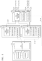
- FIG. 5 is a block diagram of a spectrum sharing system according to an example embodiment of the present disclosure
- FIGS. 6 to 8 are flowcharts for illustrating a method of operating the spectrum sharing system shown in FIG. 5 .
- the spectrum sharing system shown in FIG. 5 illustrates an embodiment in which the head-end unit 130 of the distributed antenna system DAS interoperates with the plurality of radio service devices 120 a and 120 b .
- the system controller 110 and the plurality of radio service devices 120 a and 120 b and the plurality of radio service devices 120 a and 120 b and the head-end unit 130 may be respectively and communicatively connected to each other through respective interfaces to transmit and receive information necessary for spectrum sharing access.
- the head-end unit 130 in operation S 601 , the head-end unit 130 generates information (hereinafter referred to as DAS information) of the distributed antenna system DAS and transmits the DAS information to at least one of the plurality of radio service devices 120 a and 120 b.
- DAS information information of the distributed antenna system DAS and transmits the DAS information to at least one of the plurality of radio service devices 120 a and 120 b.
- the DAS information which is information related to a radio service of the plurality of radio service devices 120 a and 120 b provided to end-user devices through the distributed antenna system DAS, may include, for example, radio access technologies respectively provided from the plurality of radio service devices 120 a and 120 b to the node units (the head-end unit 130 , the remote unit 140 , and the expansion unit 150 ) of the distributed antenna system DAS, operating parameters associated with the radio access technologies, a geographic location, a device identifier, and the like.
- any one of the plurality of radio service devices 120 a and 120 b generates interoperating information (hereinafter referred to as RSD-DAS interoperating information) of the plurality of radio service devices 120 a and 120 b and the distributed antenna system DAS based on the DAS information received from the head-end unit 130 .
- RSD-DAS interoperating information interoperating information
- the one of the plurality of radio service devices 120 a and 120 b operates as a domain proxy.
- the RSD-DAS interoperating information which is information directly or indirectly indicating whether or not the plurality of radio service devices 120 a and 120 b interoperate with the distributed antenna system DAS, may include an indication of an interoperating state, an indication of radio access technologies provided by the plurality of radio service devices 120 a and 120 b through the distributed antenna system DAS, operating parameters associated with the radio access technologies, a geographic location, a device identifier, and the like.
- the DAS information includes all information such as the radio access technologies provided by the plurality of radio service devices 120 a and 120 b , only one of the plurality of radio service devices 120 a and 120 b may generate the RSD-DAS interoperating information based on the DAS information.
- the one of the radio service devices transmits the generated RSD-DAS interoperating information to the system controller 110 , in operation S 604 , transmits its own information (hereinafter referred to as RSD information) to the system controller 110 .
- RSD information its own information
- the one of the radio service devices transmits the DAS information received from the head-end unit 130 to the system controller 110 .
- the one of the radio service devices transmits, as a domain proxy, other interoperating elements, that is, information about each of the other radio service device and the distributed antenna system DAS, to the system controller 110 together with the RSD-DAS interoperating information indicating whether or not the interoperating is performed.
- the system controller 110 allocates the shared radio resources to the plurality of radio service devices 120 a and 120 b and the distributed antenna system DAS in consideration of the interoperating state based on the received RSD-DAS interoperating information.
- the system controller 110 transmits allocation information indicating a result of the allocation to the one of the radio service devices.
- the one of the radio service devices operates according to the received allocation information.
- the one of the radio service devices transmits the allocation information to the head-end unit 130 .
- the head-end unit 130 operates according to the received allocation information.
- the one of the radio service devices transmits the allocation information to an other radio service device in addition to the head-end unit 130 so that the other radio service device also operates according to the received allocation information.
- the head-end unit 130 transmits the allocation information received from the other radio service to other elements of the distributed antenna system DAS such as the remote unit 140 and the expansion unit 150 so that the distributed antenna system DAS may operate using the allocated radio resources.
- the plurality of radio service devices 120 a and 120 b respectively generates interoperating information (hereinafter referred to as RSD # 1 -DAS interoperating information and RSD # 2 -DAS interoperating information) with the distributed antenna system DAS based on information (hereinafter referred to as DAS information) of the distributed antenna system DAS received from the head-end unit 130 .
- interoperating information hereinafter referred to as RSD # 1 -DAS interoperating information and RSD # 2 -DAS interoperating information
- DAS information information of the distributed antenna system DAS received from the head-end unit 130 .
- the head-end unit 130 may transmit the DAS information (e.g., a location of the head-end unit 130 , a location of remote units connected to the head-end unit 130 , an output power, a supporting frequency band, etc.) to the plurality of radio service devices 120 a and 120 b through a network.
- the head-end unit 130 may transmit the DAS information to the plurality of radio service devices 120 a and 120 b in an off-line manner.
- the RSD # 1 -DAS interoperating information which is information directly or indirectly indicating whether or not the radio service device 120 a interoperates with the distributed antenna system DAS, may include an indication of an interoperating state, an indication of radio access technology provided by the radio service device 120 a through the distributed antenna system DAS, operating parameters associated with the radio access technology, a geographic location, a device identifier, and the like.
- the RSD # 2 -DAS interoperating information which is information directly or indirectly indicating whether or not the radio service device 120 b interoperates with the distributed antenna system DAS, may also include an indication of an interoperating state, an indication of radio access technology provided by the radio service device 120 b through the distributed antenna system DAS, operating parameters associated with the radio access technology, a geographic location, a device identifier, and the like.
- the radio service device 120 a transmits the RSD # 1 -DAS interoperating information to the system controller 110 .
- the radio service device 120 b transmits the RSD # 2 -DAS interoperating information to the system controller 110 .
- each of the plurality of radio service devices 120 a and 120 b transmits information related to interoperation with the distributed antenna system DAS to the system controller 110 .
- the system controller 110 allocates shared radio resources to each of the plurality of radio service devices 120 a and 120 b and the distributed antenna system DAS based on the received RSD # 1 -DAS interoperating information and the RSD # 2 -DAS interoperating information.
- the system controller 110 transmits RSD # 1 -DAS allocation information indicating a result of allocating radio resources to the radio service device 120 a in consideration of interoperating the radio service device 120 a and the distributed antenna system DAS.
- the system controller 110 transmits RSD # 2 -DAS allocation information indicating a result of allocating radio resources to the radio service device 120 b in consideration of interoperating the radio service device 120 b and the distributed antenna system DAS.
- the radio service devices 120 a and 120 b respectively operate according to the pieces of received allocation information.
- the radio service devices 120 a and 120 b respectively transmit the pieces of allocation information received from the system controller 110 to the head-end unit 130 .
- the head-end unit 130 operates according to the received pieces of allocation information.
- the head-end unit 130 transmits the pieces of allocation information received from the radio service devices 120 a and 120 b to other elements of the distributed antenna system DAS such as the remote unit 140 and the expansion unit 150 so that the distributed antenna system DAS may operate using the allocated radio resources.
- the head-end unit 130 transmits information of the distributed antenna system DAS (hereinafter referred to as DAS information) to each of the plurality of radio service devices 120 a and 120 b.
- DAS information information of the distributed antenna system
- the plurality of radio service devices 120 a and 120 b respectively aggregate their own information and the DAS information to generate virtualized radio service device information (hereinafter referred to as VRSD # 1 information and VRSD # 2 information).
- the VRSD # 1 information may be information that identifies the distributed antenna system DAS as a device integrated with the radio service device 120 a or as an extension device of the radio service device 120 a .
- the VRSD # 1 information may include an indication of radio access technology provided by the radio service device 120 a through the distributed antenna system DAS, operating parameters associated with the radio access technology, a geographic location, a device identifier, and the like.
- the VRSD # 2 information may be information that identifies the distributed antenna system DAS as a device integrated with the radio service device 120 b or as an extension device of the radio service device 120 b .
- the VRSD # 2 information may include an indication of radio access technology provided by the radio service device 120 b through the distributed antenna system DAS, operating parameters associated with the radio access technology, a geographic location, a device identifier, and the like.
- the radio service device 120 a transmits the VRSD # 1 information to the system controller 110 .
- the radio service device 120 b transmits the VRSD # 2 information to the system controller 110 .
- FIG. 8 discloses an embodiment where the radio service devices 120 a and 120 b respectively transmit the VRSD # 1 information and the VRSD # 2 information to the system controller 110 such that the system controller 110 recognizes the distributed antenna system DAS respectively connected to the radio service devices 120 a and 120 b as an integrated (or extended) device.
- the system controller 110 based on the received VRSD # 1 information and the VRSD # 2 information, allocates integrally shared radio resources to the radio service device 120 a and the distributed antenna system DAS (i.e., one virtualized radio service device) and the radio service device 120 b and the distributed antenna system DAS (i.e., the other virtualized radio service device).
- the system controller 110 transmits the RSD # 1 -DAS allocation information indicating a result of allocating radio resources to the one virtualized radio service device to the radio service devices 120 a .
- the system controller 110 transmits the RSD # 2 -DAS allocation information indicating a result of allocating radio resources to the other virtualized radio service device to the radio service devices 120 b.
- the radio service device 120 a determines respective operations of the radio service device 120 a and the distributed antenna system DAS based on the received RSD # 1 -DAS allocation information.
- the radio service device 120 b determines respective operations of the radio service device 120 b and the distributed antenna system DAS based on the received RSD # 2 -DAS allocation information.
- the radio service device 120 a operates according to a result of the determination.
- the radio service device 120 b operates according to a result of the determination.
- each of the radio service devices 120 a and 120 b transmits information (hereinafter referred to as DAS operation information) related to the operation determined for the distributed antenna system DAS to the head-end unit 130 .
- DAS operation information information related to the operation determined for the distributed antenna system DAS
- the head-end unit 130 operates according to the DAS operation information.
- the head-end unit 130 transmits DAS operation information to other elements of the distributed antenna system DAS such as the remote unit 140 and the expansion unit 150 so that the distributed antenna system DAS may operate using the allocated radio resources.
- FIG. 9 is a block diagram of a spectrum sharing system according to an example embodiment of the present disclosure
- FIGS. 10 and 11 are flowcharts for illustrating a method of operating the spectrum sharing system shown in FIG. 9 .
- the spectrum sharing system shown in FIG. 9 illustrates an embodiment in which the head-end unit 130 of the distributed antenna system DAS interoperates with the plurality of radio service devices 120 a and 120 b .
- the system controller 110 and the head-end unit 130 and the plurality of radio service devices 120 a and 120 b and the head-end unit 130 may be respectively and communicatively connected to each other through respective interfaces to transmit and receive information necessary for spectrum sharing access.
- the radio service devices 120 a and 120 b respectively generate their own information (hereinafter referred to as RSD information) and transmit the RSD information to a plurality of head-end units 130 .
- RSD information own information
- the RSD information may include, for example, an indication of radio access technologies respectively provided by the radio service devices 120 a and 120 b , operating parameters associated with the radio access technologies, a geographic location, a device identifier, and the like.
- the head-end unit 130 generates interoperating information (hereinafter referred to as RSD-DAS interoperating information) of the plurality of radio service devices 120 a and 120 b and the distributed antenna system DAS based on the RSD information respectively received from the plurality of radio service devices 120 a and 120 b.
- RSD-DAS interoperating information interoperating information
- the head-end unit 130 transmits the RSD-DAS interoperating information to the system controller 110 .
- the head-end unit 130 transmits its own information (hereinafter referred to as DAS information) to the system controller 110 .
- the head-end unit 130 transmits the RSD information received from the radio service devices 120 a and 120 b to the system controller 110 .
- the head-end unit 130 transmits, as a domain proxy, other interoperating elements, that is, respective information about the radio service devices 120 a and 120 b and the distributed antenna system DAS, to the system controller 110 together with the RSD-DAS interoperating information indicating whether or not the interoperating is performed.
- the system controller 110 allocates the shared radio resources to the plurality of radio service devices 120 a and 120 b and the distributed antenna system DAS in consideration of the interoperating state based on the received RSD-DAS interoperating information.
- the system controller 110 transmits allocation information indicating a result of the allocation to the head-end unit 130 , and in operation S 1008 , the head-end unit 130 operates according to the received allocation information.
- the head-end unit 130 transmits the allocation information received from the system controller 110 to other elements of the distributed antenna system DAS such as the remote unit 140 and the expansion unit 150 so that the distributed antenna system DAS may operate using the allocated radio resources.
- the head-end unit 130 transmits the allocation information to the radio service devices 120 a and 120 b , and in operation S 1010 , each of the radio service devices 120 a and 120 b operates according to the received allocation information.
- the radio service device 120 a transmits its own information (hereinafter referred to as RSD # 1 information) to the head-end unit 130
- the radio service device 120 b transmits its own information (hereinafter referred to as RSD # 2 information) to the head-end unit 130
- the head-end unit 130 combines respective information of the distributed antenna system DAS and the radio service devices 120 a and 120 b to generate virtualized radio service device information (hereinafter referred to as VRSD # 1 information and VRSD # 2 information).
- the VRSD # 1 information may be information that identifies the distributed antenna system DAS as a device integrated with the radio service device 120 a or as an extension device of the radio service device 120 a .
- the VRSD # 1 information may include radio access technology provided by the radio service device 120 a through the distributed antenna system DAS, operating parameters associated with the radio access technology, a geographic location, a device identifier, and the like.
- the VRSD # 2 information may be information that identifies the distributed antenna system DAS as a device integrated with the radio service device 120 b or as an extension device of the radio service device 120 b .
- the VRSD # 2 information may include radio access technology provided by the radio service device 120 b through the distributed antenna system DAS, operating parameters associated with the radio access technology, a geographic location, a device identifier, and the like.
- the head-end unit 130 transmits the VRSD # 1 information and the VRSD # 2 information to the system controller 110 .
- the head-end unit 130 transmits the VRSD # 1 information and the VRSD # 2 information to the system controller 110 such that the distributed antenna system DAS operates integrally with each of the plurality of radio service devices 120 a and 120 b and the system controller 110 recognizes the distributed antenna system DAS as a device integrated (or extended) with each of the plurality of radio service devices 120 a and 120 b.
- the system controller 110 based on the received VRSD # 1 information and the VRSD # 2 information, allocates shared radio resources to the radio service device 120 a and the distributed antenna system DAS (i.e., one virtualized radio service device) and the radio service device 120 b and the distributed antenna system DAS (i.e., the other virtualized radio service device), respectively.
- the distributed antenna system DAS i.e., one virtualized radio service device
- the radio service device 120 b and the distributed antenna system DAS i.e., the other virtualized radio service device
- the system controller 110 transmits the RSD # 1 -DAS allocation information indicating a result of allocating radio resources to the one virtualized radio service device and the RSD # 2 -DAS allocation information indicating a result of allocating radio resources to the other virtualized radio service device to the head-end unit 130 , respectively.
- the head-end unit 130 determines respective operations of the radio service device 120 a , the radio service device 120 b , and the distributed antenna system DAS based on the received RSD # 1 -DAS allocation information and the RSD # 2 -DAS allocation information.
- the head-end unit 130 operates according to a result of the determination of the distributed antenna system DAS.
- the head-end unit 130 transmits pieces of Information related to the determined result to other elements of the distributed antenna system DAS such as the remote unit 140 and the expansion unit 150 so that the distributed antenna system DAS may operate using the allocated radio resources.
- the head-end unit 130 transmits information (RSD # 1 operation information) related to the operation determined for the radio service device 120 a to the radio service device 120 a
- the head-end unit 130 transmits information (RSD # 2 operation information) related to the operation determined for the radio service device 120 b to the radio service device 120 b
- each of the radio service devices 120 b and 120 b operates according to the received operation information.
- FIGS. 3 to 11 describe the embodiment in which the head-end unit 130 interoperates with the plurality of radio service devices 120 a and 120 b above. However, even in an embodiment in which the remote unit 130 interoperates with at least one radio service device, the allocation operation of the shared radio resources as shown in FIGS. 3 to 11 will be possible.
- FIGS. 4 , 6 to 8 , 10 , and 11 and the methods described with reference thereto include one or more operations and/or actions for achieving the methods.
- the operations and/or actions for achieving the methods may be interchanged with one another without departing from the scope of the claims.
- the order and/or use of specific operations and/or actions may be modified without departing from the scope of the claims, unless a certain order for the operations and/or actions is specified.
- An example of a spectrum sharing system of the present disclosure is a citizens Broadband Radio Service (CBRS) system specified by the United States Federal Communications Commission (FCC).
- CBRS citizens Broadband Radio Service
- FCC United States Federal Communications Commission
- technologies proposed in the present disclosure have sometimes been described on the premise of the CBRS system. However, such a description does not limit the technologies proposed in the present disclosure.
- the present disclosure is applicable to various spectrum sharing systems other than the CBRS system.
- various operations of the methods described above may be performed by any suitable means capable of performing corresponding functions.
- the means includes, but is not limited to, various hardware and/or software components and/or modules such as an application specific integrated circuit (ASIC) or a processor.
- ASIC application specific integrated circuit
- processor a processor
- the various illustrative logic blocks, components, or circuits described in connection with the present disclosure may be implemented or performed by a general-purpose processor designed to perform the functions disclosed herein, a digital signal processor (DSP), an ASIC, a field-programmable gate array (FPGA) or other programmable logic device (PLD), a discrete gate or transistor logic device, discrete hardware components, or any combination thereof.
- DSP digital signal processor
- FPGA field-programmable gate array
- PLD programmable logic device
- the general-purpose processor may be a microprocessor, but may alternatively be any commercially available processor, controller, microcontroller, or state machine.
- the processor may also be implemented in a combination of computing devices, for example, a combination of the DSP and the microprocessor, a plurality of microprocessors, one or more microprocessors in connection with a DSP core, or any other configuration.
- a spectrum sharing system may allocate and operate shared radio resources considering interoperating of the distributed antenna system DAS, thereby preventing unexpected interference from occurring at a specific area and/or at a specific time due to interoperating of the distributed antenna system DAS, and efficiently utilizing the shared radio resources.
Abstract
Description
Claims (19)
Priority Applications (1)
| Application Number | Priority Date | Filing Date | Title |
|---|---|---|---|
| US16/819,337 US11722906B2 (en) | 2018-12-12 | 2020-03-16 | Method of operating spectrum sharing system interoperating with distributed antenna system |
Applications Claiming Priority (4)
| Application Number | Priority Date | Filing Date | Title |
|---|---|---|---|
| KR20180160328 | 2018-12-12 | ||
| KR10-2018-0160328 | 2018-12-12 | ||
| KR1020190024415A KR102659665B1 (en) | 2018-12-12 | 2019-02-28 | Method of operating spectrum shared system interoperating with distributed antenna system |
| KR10-2019-0024415 | 2019-02-28 |
Related Child Applications (1)
| Application Number | Title | Priority Date | Filing Date |
|---|---|---|---|
| US16/819,337 Continuation US11722906B2 (en) | 2018-12-12 | 2020-03-16 | Method of operating spectrum sharing system interoperating with distributed antenna system |
Publications (2)
| Publication Number | Publication Date |
|---|---|
| US20200196156A1 US20200196156A1 (en) | 2020-06-18 |
| US11729626B2 true US11729626B2 (en) | 2023-08-15 |
Family
ID=67396887
Family Applications (3)
| Application Number | Title | Priority Date | Filing Date |
|---|---|---|---|
| US16/421,939 Active US11729626B2 (en) | 2018-12-12 | 2019-05-24 | Method of operating spectrum sharing system interoperating with distributed antenna system |
| US16/819,337 Active US11722906B2 (en) | 2018-12-12 | 2020-03-16 | Method of operating spectrum sharing system interoperating with distributed antenna system |
| US18/341,103 Pending US20230331367A1 (en) | 2018-12-12 | 2023-06-26 | Method of operating spectrum sharing system interoperating with distributed antenna system |
Family Applications After (2)
| Application Number | Title | Priority Date | Filing Date |
|---|---|---|---|
| US16/819,337 Active US11722906B2 (en) | 2018-12-12 | 2020-03-16 | Method of operating spectrum sharing system interoperating with distributed antenna system |
| US18/341,103 Pending US20230331367A1 (en) | 2018-12-12 | 2023-06-26 | Method of operating spectrum sharing system interoperating with distributed antenna system |
Country Status (3)
| Country | Link |
|---|---|
| US (3) | US11729626B2 (en) |
| EP (3) | EP4340535A2 (en) |
| KR (1) | KR102612293B1 (en) |
Families Citing this family (3)
| Publication number | Priority date | Publication date | Assignee | Title |
|---|---|---|---|---|
| US11115866B2 (en) * | 2019-07-31 | 2021-09-07 | Corning Research & Development Corporation | Coordination of shared spectrum distribution to remote units in distributed radio communications systems |
| JP2023502393A (en) | 2019-11-18 | 2023-01-24 | コムスコープ テクノロジーズ リミティド ライアビリティ カンパニー | Systems and methods for multi-operator distributed antenna systems |
| WO2023250437A1 (en) * | 2022-06-22 | 2023-12-28 | Commscope Technologies Llc | Digital donor card for a distributed antenna unit supporting multiple virtual radio points |
Citations (18)
| Publication number | Priority date | Publication date | Assignee | Title |
|---|---|---|---|---|
| US20160330676A1 (en) | 2015-02-02 | 2016-11-10 | Telefonaktiebolaget Lm Ericsson (Publ) | Cell search for d2d enabled ues in out of network coverage |
| US20170064642A1 (en) | 2014-02-21 | 2017-03-02 | Commscope Technologies Llc | Self-optimizing network entity for a telecommunications system |
| US20170208454A1 (en) * | 2016-01-14 | 2017-07-20 | Qualcomm Incorporated | Spectrum access server support of resource assignments based on radio access network coexistence information |
| US20170238136A1 (en) * | 2011-08-18 | 2017-08-17 | Rivada Research, Llc | Method and System for Improving the Location of Fixed Wireless CBSD Nodes |
| US20170339660A1 (en) | 2014-11-10 | 2017-11-23 | Telefonaktiebolaget Lm Ericsson (Publ) | Signaling and Using CRS Muting in Shared Cell for Positioning |
| EP3343971A1 (en) | 2016-12-27 | 2018-07-04 | Intel IP Corporation | Network controller, radio access node, method for controlling a radio communication network and method for providing radio access |
| US20180288621A1 (en) | 2017-03-31 | 2018-10-04 | Nokia Technologies Oy | Coordinating Spectrum Authorization For Backhaul Connections |
| AU2017262114A1 (en) | 2016-05-13 | 2018-11-22 | Sony Corporation | Frequency spectrum management apparatus and method, electronic apparatus and method, and wireless communication system |
| US20190223025A1 (en) * | 2018-01-15 | 2019-07-18 | Charter Communications Operating, Llc | Methods and apparatus for allocation and reconciliation of quasi-licensed wireless spectrum across multiple entities |
| US20190335336A1 (en) * | 2017-09-21 | 2019-10-31 | Telefonaktiebolaget Lm Ericsson (Publ) | Method and apparatus for handling interference connection types in citizens broadband radio service devices band |
| US20190394704A1 (en) * | 2018-06-21 | 2019-12-26 | At&T Intellectual Property I, L.P. | Multi-operator spectrum resource sharing management |
| US20200008007A1 (en) * | 2018-06-29 | 2020-01-02 | Apple Inc. | Device Support for Scalable Neutral Host and Private LTE/5G Network Discovery, and Device Mobility |
| US20200170061A1 (en) * | 2017-06-06 | 2020-05-28 | Telefonaktiebolaget Lm Ericsson (Publ) | A method for establishing a connection between a neutral host network and one or more virtual radio access networks |
| US20200252933A1 (en) * | 2019-01-31 | 2020-08-06 | Charter Communications Operating, Llc | Methods and apparatus for frequency transition management in a quasi-licensed wireless system |
| US20200275457A1 (en) * | 2019-02-27 | 2020-08-27 | Charter Communications Operating, Llc | Methods and apparatus for wireless signal maximization and management in a quasi-licensed wireless system |
| US20200305159A1 (en) * | 2019-03-20 | 2020-09-24 | Commscope Technologies Llc | Cloud radio access network implementing a citizens broadband radio service system |
| US20200322786A1 (en) | 2016-07-22 | 2020-10-08 | Guangdong Oppo Mobile Telecommunications Corp., Ltd. | Information transmission method and device |
| US20210409549A1 (en) * | 2017-12-18 | 2021-12-30 | Incnetworks, Inc. | System, Network, Device and Stacked Spectrum Method for Implementing Spectrum Sharing of Multiple Contiguous and Non-Contiguous Spectrum Bands Utilizing Universal Wireless Access Gateways to Enable Dynamic Security and Bandwidth Policy Management |
-
2019
- 2019-05-24 US US16/421,939 patent/US11729626B2/en active Active
- 2019-07-02 EP EP24154754.6A patent/EP4340535A2/en active Pending
- 2019-07-02 EP EP21198345.7A patent/EP3958602A1/en active Pending
- 2019-07-02 EP EP19183961.2A patent/EP3668139B1/en active Active
-
2020
- 2020-03-16 US US16/819,337 patent/US11722906B2/en active Active
-
2022
- 2022-02-23 KR KR1020220023590A patent/KR102612293B1/en active IP Right Grant
-
2023
- 2023-06-26 US US18/341,103 patent/US20230331367A1/en active Pending
Patent Citations (18)
| Publication number | Priority date | Publication date | Assignee | Title |
|---|---|---|---|---|
| US20170238136A1 (en) * | 2011-08-18 | 2017-08-17 | Rivada Research, Llc | Method and System for Improving the Location of Fixed Wireless CBSD Nodes |
| US20170064642A1 (en) | 2014-02-21 | 2017-03-02 | Commscope Technologies Llc | Self-optimizing network entity for a telecommunications system |
| US20170339660A1 (en) | 2014-11-10 | 2017-11-23 | Telefonaktiebolaget Lm Ericsson (Publ) | Signaling and Using CRS Muting in Shared Cell for Positioning |
| US20160330676A1 (en) | 2015-02-02 | 2016-11-10 | Telefonaktiebolaget Lm Ericsson (Publ) | Cell search for d2d enabled ues in out of network coverage |
| US20170208454A1 (en) * | 2016-01-14 | 2017-07-20 | Qualcomm Incorporated | Spectrum access server support of resource assignments based on radio access network coexistence information |
| AU2017262114A1 (en) | 2016-05-13 | 2018-11-22 | Sony Corporation | Frequency spectrum management apparatus and method, electronic apparatus and method, and wireless communication system |
| US20200322786A1 (en) | 2016-07-22 | 2020-10-08 | Guangdong Oppo Mobile Telecommunications Corp., Ltd. | Information transmission method and device |
| EP3343971A1 (en) | 2016-12-27 | 2018-07-04 | Intel IP Corporation | Network controller, radio access node, method for controlling a radio communication network and method for providing radio access |
| US20180288621A1 (en) | 2017-03-31 | 2018-10-04 | Nokia Technologies Oy | Coordinating Spectrum Authorization For Backhaul Connections |
| US20200170061A1 (en) * | 2017-06-06 | 2020-05-28 | Telefonaktiebolaget Lm Ericsson (Publ) | A method for establishing a connection between a neutral host network and one or more virtual radio access networks |
| US20190335336A1 (en) * | 2017-09-21 | 2019-10-31 | Telefonaktiebolaget Lm Ericsson (Publ) | Method and apparatus for handling interference connection types in citizens broadband radio service devices band |
| US20210409549A1 (en) * | 2017-12-18 | 2021-12-30 | Incnetworks, Inc. | System, Network, Device and Stacked Spectrum Method for Implementing Spectrum Sharing of Multiple Contiguous and Non-Contiguous Spectrum Bands Utilizing Universal Wireless Access Gateways to Enable Dynamic Security and Bandwidth Policy Management |
| US20190223025A1 (en) * | 2018-01-15 | 2019-07-18 | Charter Communications Operating, Llc | Methods and apparatus for allocation and reconciliation of quasi-licensed wireless spectrum across multiple entities |
| US20190394704A1 (en) * | 2018-06-21 | 2019-12-26 | At&T Intellectual Property I, L.P. | Multi-operator spectrum resource sharing management |
| US20200008007A1 (en) * | 2018-06-29 | 2020-01-02 | Apple Inc. | Device Support for Scalable Neutral Host and Private LTE/5G Network Discovery, and Device Mobility |
| US20200252933A1 (en) * | 2019-01-31 | 2020-08-06 | Charter Communications Operating, Llc | Methods and apparatus for frequency transition management in a quasi-licensed wireless system |
| US20200275457A1 (en) * | 2019-02-27 | 2020-08-27 | Charter Communications Operating, Llc | Methods and apparatus for wireless signal maximization and management in a quasi-licensed wireless system |
| US20200305159A1 (en) * | 2019-03-20 | 2020-09-24 | Commscope Technologies Llc | Cloud radio access network implementing a citizens broadband radio service system |
Non-Patent Citations (9)
| Title |
|---|
| Atis: "Neutral Host Solutions for Multi-Operator Wireless Coverage in Managed Spaces", Alliance for Telecommunications Industry Solutions, ATIS-I-0000052, Oct. 11, 2016 (Oct. 11, 2016), pp. 1-17 (total 22 pages). |
| Extended European Search Report dated Jan. 21, 2022 in European Application No. 21198345.7. |
| Extended European Search Report dated Jan. 24, 2020 from European Patent Office in Application No. EP19183961.2. |
| Mun, Kyung, "Making Neutral Host a Reality with OnGo", Dec. 2018, CBRS Alliance (Year: 2018). * |
| Non-Final Office issued in the U.S. Patent and Trademark Office in related U.S. Appl. No. 16/819,337 dated Sep. 14, 2022. |
| Office Action dated Mar. 10, 2023 from the Korean Patent Office in Application No. 10-2019-0024415. |
| Vinay Bheemesh et al: "Radio resource management in coordinated antenna system deployments" Applied Computing, ACM, 2 Penn Plaza, Suite 701 New York NY 10121-0701 USA, Mar. 18, 2013 (Mar. 18, 2013), pp. 573-576 (total 4 pages). |
| Winn Forum, "CBRS Deployment Guidelines for Installers Document WINNF-TR-5001", Dec. 11, 2018, Version V.1.0.0., pp. 1-4 (8 total pages). |
| Winn Forum: "Interim SAS to CBSD Protocol Technical Report-A Historical Document WINNF-15-H-0023 Spectrum Sharing Committee Work Group 3 (Protocols) SAS to CBSD Protocol Terms, Conditions & Notices", Jan. 3, 2017 (Jan. 3, 2017), total 24 pages. |
Also Published As
| Publication number | Publication date |
|---|---|
| US11722906B2 (en) | 2023-08-08 |
| KR20220029621A (en) | 2022-03-08 |
| KR20220029620A (en) | 2022-03-08 |
| EP3668139A1 (en) | 2020-06-17 |
| EP4340535A2 (en) | 2024-03-20 |
| US20200221312A1 (en) | 2020-07-09 |
| KR102612293B1 (en) | 2023-12-11 |
| US20200196156A1 (en) | 2020-06-18 |
| EP3958602A1 (en) | 2022-02-23 |
| EP3668139B1 (en) | 2021-10-20 |
| US20230331367A1 (en) | 2023-10-19 |
Similar Documents
| Publication | Publication Date | Title |
|---|---|---|
| US20230331367A1 (en) | Method of operating spectrum sharing system interoperating with distributed antenna system | |
| US9241332B2 (en) | System and method for managing resources in a communication system | |
| US11153890B2 (en) | Method and system for managing UE-to-UE interference in a mobile telecommunication network | |
| RU2713929C2 (en) | Device, method and program | |
| US20100195590A1 (en) | Method and apparatus for radio spectrum sensing or monitoring | |
| RU2760569C2 (en) | Device, method and recordable storage media | |
| JP6947483B2 (en) | Unlicensed carrier processing methods, equipment, and systems | |
| WO2020150102A1 (en) | Resource allocation across coexisting radio access technologies | |
| US20230353193A1 (en) | Method of interworking between spectrum sharing system and distributed antenna system | |
| CN105704724A (en) | Control equipment and method of wireless communication system for supporting cognitive radio | |
| JP2012060455A (en) | Method for coexistence of heterogeneous cognitive radio systems | |
| WO2015149484A1 (en) | Frequency band sharing method, device, system, and related computer storage medium | |
| US10039007B2 (en) | Method of operating entities in coexistence management system | |
| US20210391896A1 (en) | Method of operating distributed antenna system interworking with spectrum sharing system | |
| KR102659511B1 (en) | Method of operating spectrum shared system interoperating with distributed antenna system | |
| KR102659665B1 (en) | Method of operating spectrum shared system interoperating with distributed antenna system | |
| KR20200072379A (en) | Method of operating spectrum shared system interoperating with distributed antenna system | |
| RU2711413C2 (en) | Communication control device, storage device, communication control mode determining device and server device | |
| US20240015815A1 (en) | Communication method, communication apparatus, and base station | |
| CN110838931B (en) | Method, apparatus and computer readable medium for automatic configuration in a communication system | |
| WO2022097343A1 (en) | Base station device, relay station device, communication control method, and communication control program | |
| KR20210136232A (en) | Distributed antenna system interoperating with spectrum shared system and operating method thereof | |
| CN117479185A (en) | Seamless policing access point updates to ensure persistent client connectivity | |
| KR20120026990A (en) | System and method for managing resource in communication system |
Legal Events
| Date | Code | Title | Description |
|---|---|---|---|
| AS | Assignment |
Owner name: SOLID, INC., KOREA, REPUBLIC OF Free format text: ASSIGNMENT OF ASSIGNORS INTEREST;ASSIGNORS:KIM, OK JIN;KIM, DAE YOUNG;REEL/FRAME:049287/0044 Effective date: 20190520 |
|
| FEPP | Fee payment procedure |
Free format text: ENTITY STATUS SET TO UNDISCOUNTED (ORIGINAL EVENT CODE: BIG.); ENTITY STATUS OF PATENT OWNER: SMALL ENTITY |
|
| FEPP | Fee payment procedure |
Free format text: ENTITY STATUS SET TO SMALL (ORIGINAL EVENT CODE: SMAL); ENTITY STATUS OF PATENT OWNER: SMALL ENTITY |
|
| STPP | Information on status: patent application and granting procedure in general |
Free format text: DOCKETED NEW CASE - READY FOR EXAMINATION |
|
| STPP | Information on status: patent application and granting procedure in general |
Free format text: NON FINAL ACTION MAILED |
|
| STPP | Information on status: patent application and granting procedure in general |
Free format text: RESPONSE TO NON-FINAL OFFICE ACTION ENTERED AND FORWARDED TO EXAMINER |
|
| STPP | Information on status: patent application and granting procedure in general |
Free format text: FINAL REJECTION MAILED |
|
| STPP | Information on status: patent application and granting procedure in general |
Free format text: NOTICE OF ALLOWANCE MAILED -- APPLICATION RECEIVED IN OFFICE OF PUBLICATIONS |
|
| STPP | Information on status: patent application and granting procedure in general |
Free format text: PUBLICATIONS -- ISSUE FEE PAYMENT VERIFIED |
|
| STCF | Information on status: patent grant |
Free format text: PATENTED CASE |