US11725003B2 - Amine derivative and an organic electroluminescent device thereof - Google Patents
Amine derivative and an organic electroluminescent device thereof Download PDFInfo
- Publication number
- US11725003B2 US11725003B2 US16/848,401 US202016848401A US11725003B2 US 11725003 B2 US11725003 B2 US 11725003B2 US 202016848401 A US202016848401 A US 202016848401A US 11725003 B2 US11725003 B2 US 11725003B2
- Authority
- US
- United States
- Prior art keywords
- group
- unsubstituted
- substituted
- compound
- present disclosure
- Prior art date
- Legal status (The legal status is an assumption and is not a legal conclusion. Google has not performed a legal analysis and makes no representation as to the accuracy of the status listed.)
- Active, expires
Links
- 150000001412 amines Chemical class 0.000 title claims abstract description 41
- 239000010410 layer Substances 0.000 claims abstract description 131
- 238000000605 extraction Methods 0.000 claims abstract description 38
- 239000012044 organic layer Substances 0.000 claims abstract description 13
- 125000003118 aryl group Chemical group 0.000 claims description 55
- -1 ethylphenyl Chemical group 0.000 claims description 39
- 125000001072 heteroaryl group Chemical group 0.000 claims description 32
- 229910052757 nitrogen Inorganic materials 0.000 claims description 23
- 125000005549 heteroarylene group Chemical group 0.000 claims description 21
- 125000000732 arylene group Chemical group 0.000 claims description 20
- 230000005525 hole transport Effects 0.000 claims description 19
- 125000000008 (C1-C10) alkyl group Chemical group 0.000 claims description 14
- 125000006732 (C1-C15) alkyl group Chemical group 0.000 claims description 14
- 125000001495 ethyl group Chemical group [H]C([H])([H])C([H])([H])* 0.000 claims description 14
- 125000002496 methyl group Chemical group [H]C([H])([H])* 0.000 claims description 14
- 125000000484 butyl group Chemical group [H]C([*])([H])C([H])([H])C([H])([H])C([H])([H])[H] 0.000 claims description 13
- 125000001436 propyl group Chemical group [H]C([*])([H])C([H])([H])C([H])([H])[H] 0.000 claims description 13
- 229910052739 hydrogen Inorganic materials 0.000 claims description 8
- 239000001257 hydrogen Substances 0.000 claims description 8
- 125000004051 hexyl group Chemical group [H]C([H])([H])C([H])([H])C([H])([H])C([H])([H])C([H])([H])C([H])([H])* 0.000 claims description 5
- 229910052760 oxygen Inorganic materials 0.000 claims description 5
- 125000001147 pentyl group Chemical group C(CCCC)* 0.000 claims description 5
- 125000001997 phenyl group Chemical group [H]C1=C([H])C([H])=C(*)C([H])=C1[H] 0.000 claims description 5
- 229910052717 sulfur Inorganic materials 0.000 claims description 5
- 125000003187 heptyl group Chemical group [H]C([*])([H])C([H])([H])C([H])([H])C([H])([H])C([H])([H])C([H])([H])C([H])([H])[H] 0.000 claims description 4
- 125000004435 hydrogen atom Chemical group [H]* 0.000 claims description 4
- 125000002347 octyl group Chemical group [H]C([*])([H])C([H])([H])C([H])([H])C([H])([H])C([H])([H])C([H])([H])C([H])([H])C([H])([H])[H] 0.000 claims description 4
- 125000003944 tolyl group Chemical group 0.000 claims description 2
- 239000000463 material Substances 0.000 abstract description 93
- 125000001424 substituent group Chemical group 0.000 abstract description 28
- 125000003983 fluorenyl group Chemical group C1(=CC=CC=2C3=CC=CC=C3CC12)* 0.000 abstract description 3
- 125000003785 benzimidazolyl group Chemical group N1=C(NC2=C1C=CC=C2)* 0.000 abstract 1
- 125000001164 benzothiazolyl group Chemical group S1C(=NC2=C1C=CC=C2)* 0.000 abstract 1
- 125000004541 benzoxazolyl group Chemical group O1C(=NC2=C1C=CC=C2)* 0.000 abstract 1
- 150000004985 diamines Chemical class 0.000 abstract 1
- 150000001875 compounds Chemical class 0.000 description 65
- 230000015572 biosynthetic process Effects 0.000 description 58
- 238000003786 synthesis reaction Methods 0.000 description 58
- 239000000047 product Substances 0.000 description 39
- 239000007787 solid Substances 0.000 description 35
- IJGRMHOSHXDMSA-UHFFFAOYSA-N Atomic nitrogen Chemical compound N#N IJGRMHOSHXDMSA-UHFFFAOYSA-N 0.000 description 32
- 238000002347 injection Methods 0.000 description 30
- 239000007924 injection Substances 0.000 description 30
- HEDRZPFGACZZDS-MICDWDOJSA-N Trichloro(2H)methane Chemical compound [2H]C(Cl)(Cl)Cl HEDRZPFGACZZDS-MICDWDOJSA-N 0.000 description 24
- QARVLSVVCXYDNA-UHFFFAOYSA-N bromobenzene Chemical compound BrC1=CC=CC=C1 QARVLSVVCXYDNA-UHFFFAOYSA-N 0.000 description 22
- YXFVVABEGXRONW-UHFFFAOYSA-N Toluene Chemical compound CC1=CC=CC=C1 YXFVVABEGXRONW-UHFFFAOYSA-N 0.000 description 21
- 238000001819 mass spectrum Methods 0.000 description 19
- 239000010408 film Substances 0.000 description 16
- 229910052751 metal Inorganic materials 0.000 description 16
- 239000002184 metal Substances 0.000 description 16
- 238000000034 method Methods 0.000 description 14
- 125000000217 alkyl group Chemical group 0.000 description 13
- 230000000052 comparative effect Effects 0.000 description 13
- 238000001704 evaporation Methods 0.000 description 13
- 230000008020 evaporation Effects 0.000 description 13
- 239000000203 mixture Substances 0.000 description 13
- UHOVQNZJYSORNB-UHFFFAOYSA-N Benzene Chemical compound C1=CC=CC=C1 UHOVQNZJYSORNB-UHFFFAOYSA-N 0.000 description 12
- OKKJLVBELUTLKV-UHFFFAOYSA-N Methanol Chemical compound OC OKKJLVBELUTLKV-UHFFFAOYSA-N 0.000 description 12
- 229940125904 compound 1 Drugs 0.000 description 12
- 239000000758 substrate Substances 0.000 description 12
- 238000005160 1H NMR spectroscopy Methods 0.000 description 11
- 230000000903 blocking effect Effects 0.000 description 11
- 125000004432 carbon atom Chemical group C* 0.000 description 11
- VYPSYNLAJGMNEJ-UHFFFAOYSA-N silicon dioxide Inorganic materials O=[Si]=O VYPSYNLAJGMNEJ-UHFFFAOYSA-N 0.000 description 11
- 239000002356 single layer Substances 0.000 description 11
- TVIVIEFSHFOWTE-UHFFFAOYSA-K tri(quinolin-8-yloxy)alumane Chemical compound [Al+3].C1=CN=C2C([O-])=CC=CC2=C1.C1=CN=C2C([O-])=CC=CC2=C1.C1=CN=C2C([O-])=CC=CC2=C1 TVIVIEFSHFOWTE-UHFFFAOYSA-K 0.000 description 11
- LFQSCWFLJHTTHZ-UHFFFAOYSA-N Ethanol Chemical compound CCO LFQSCWFLJHTTHZ-UHFFFAOYSA-N 0.000 description 10
- ZUOUZKKEUPVFJK-UHFFFAOYSA-N diphenyl Chemical compound C1=CC=CC=C1C1=CC=CC=C1 ZUOUZKKEUPVFJK-UHFFFAOYSA-N 0.000 description 10
- PQXKHYXIUOZZFA-UHFFFAOYSA-M lithium fluoride Chemical compound [Li+].[F-] PQXKHYXIUOZZFA-UHFFFAOYSA-M 0.000 description 10
- 238000000425 proton nuclear magnetic resonance spectrum Methods 0.000 description 10
- 239000007983 Tris buffer Substances 0.000 description 9
- BJXYHBKEQFQVES-NWDGAFQWSA-N enpatoran Chemical compound N[C@H]1CN(C[C@H](C1)C(F)(F)F)C1=C2C=CC=NC2=C(C=C1)C#N BJXYHBKEQFQVES-NWDGAFQWSA-N 0.000 description 9
- 239000000706 filtrate Substances 0.000 description 9
- 239000011521 glass Substances 0.000 description 9
- IOQORVDNYPOZPL-VQTJNVASSA-N (5S,6R)-5-(4-chlorophenyl)-6-cyclopropyl-3-[6-methoxy-5-(4-methylimidazol-1-yl)pyridin-2-yl]-5,6-dihydro-2H-1,2,4-oxadiazine Chemical compound ClC1=CC=C(C=C1)[C@@H]1NC(=NO[C@@H]1C1CC1)C1=NC(=C(C=C1)N1C=NC(=C1)C)OC IOQORVDNYPOZPL-VQTJNVASSA-N 0.000 description 8
- ZYZCALPXKGUGJI-DDVDASKDSA-M (e,3r,5s)-7-[3-(4-fluorophenyl)-2-phenyl-5-propan-2-ylimidazol-4-yl]-3,5-dihydroxyhept-6-enoate Chemical compound C=1C=C(F)C=CC=1N1C(\C=C\[C@@H](O)C[C@@H](O)CC([O-])=O)=C(C(C)C)N=C1C1=CC=CC=C1 ZYZCALPXKGUGJI-DDVDASKDSA-M 0.000 description 8
- YSUIQYOGTINQIN-UZFYAQMZSA-N 2-amino-9-[(1S,6R,8R,9S,10R,15R,17R,18R)-8-(6-aminopurin-9-yl)-9,18-difluoro-3,12-dihydroxy-3,12-bis(sulfanylidene)-2,4,7,11,13,16-hexaoxa-3lambda5,12lambda5-diphosphatricyclo[13.2.1.06,10]octadecan-17-yl]-1H-purin-6-one Chemical compound NC1=NC2=C(N=CN2[C@@H]2O[C@@H]3COP(S)(=O)O[C@@H]4[C@@H](COP(S)(=O)O[C@@H]2[C@@H]3F)O[C@H]([C@H]4F)N2C=NC3=C2N=CN=C3N)C(=O)N1 YSUIQYOGTINQIN-UZFYAQMZSA-N 0.000 description 8
- WFOVEDJTASPCIR-UHFFFAOYSA-N 3-[(4-methyl-5-pyridin-4-yl-1,2,4-triazol-3-yl)methylamino]-n-[[2-(trifluoromethyl)phenyl]methyl]benzamide Chemical compound N=1N=C(C=2C=CN=CC=2)N(C)C=1CNC(C=1)=CC=CC=1C(=O)NCC1=CC=CC=C1C(F)(F)F WFOVEDJTASPCIR-UHFFFAOYSA-N 0.000 description 8
- IJRKLHTZAIFUTB-UHFFFAOYSA-N 5-nitro-2-(2-phenylethylamino)benzoic acid Chemical compound OC(=O)C1=CC([N+]([O-])=O)=CC=C1NCCC1=CC=CC=C1 IJRKLHTZAIFUTB-UHFFFAOYSA-N 0.000 description 8
- MXZNUGFCDVAXLG-CHWSQXEVSA-N [(2S)-1-[(2R)-3-methyl-2-(pyridine-4-carbonylamino)butanoyl]pyrrolidin-2-yl]boronic acid Chemical compound CC(C)[C@@H](NC(=O)c1ccncc1)C(=O)N1CCC[C@@H]1B(O)O MXZNUGFCDVAXLG-CHWSQXEVSA-N 0.000 description 8
- YRKCREAYFQTBPV-UHFFFAOYSA-N acetylacetone Chemical compound CC(=O)CC(C)=O YRKCREAYFQTBPV-UHFFFAOYSA-N 0.000 description 8
- 238000006243 chemical reaction Methods 0.000 description 8
- 229940126208 compound 22 Drugs 0.000 description 8
- 229940126540 compound 41 Drugs 0.000 description 8
- 238000012360 testing method Methods 0.000 description 8
- 229910052782 aluminium Inorganic materials 0.000 description 7
- 229920000642 polymer Polymers 0.000 description 7
- PYRKKGOKRMZEIT-UHFFFAOYSA-N 2-[6-(2-cyclopropylethoxy)-9-(2-hydroxy-2-methylpropyl)-1h-phenanthro[9,10-d]imidazol-2-yl]-5-fluorobenzene-1,3-dicarbonitrile Chemical compound C1=C2C3=CC(CC(C)(O)C)=CC=C3C=3NC(C=4C(=CC(F)=CC=4C#N)C#N)=NC=3C2=CC=C1OCCC1CC1 PYRKKGOKRMZEIT-UHFFFAOYSA-N 0.000 description 6
- TVTJUIAKQFIXCE-HUKYDQBMSA-N 2-amino-9-[(2R,3S,4S,5R)-4-fluoro-3-hydroxy-5-(hydroxymethyl)oxolan-2-yl]-7-prop-2-ynyl-1H-purine-6,8-dione Chemical compound NC=1NC(C=2N(C(N(C=2N=1)[C@@H]1O[C@@H]([C@H]([C@H]1O)F)CO)=O)CC#C)=O TVTJUIAKQFIXCE-HUKYDQBMSA-N 0.000 description 6
- XZYQBYQGHHGXBC-UHFFFAOYSA-N 4-(1,3-benzoxazol-2-yl)aniline Chemical compound C1=CC(N)=CC=C1C1=NC2=CC=CC=C2O1 XZYQBYQGHHGXBC-UHFFFAOYSA-N 0.000 description 6
- 239000004305 biphenyl Substances 0.000 description 6
- 229940125851 compound 27 Drugs 0.000 description 6
- 238000005401 electroluminescence Methods 0.000 description 6
- 230000009477 glass transition Effects 0.000 description 6
- MFRIHAYPQRLWNB-UHFFFAOYSA-N sodium tert-butoxide Chemical compound [Na+].CC(C)(C)[O-] MFRIHAYPQRLWNB-UHFFFAOYSA-N 0.000 description 6
- BWHDROKFUHTORW-UHFFFAOYSA-N tritert-butylphosphane Chemical compound CC(C)(C)P(C(C)(C)C)C(C)(C)C BWHDROKFUHTORW-UHFFFAOYSA-N 0.000 description 6
- PKJBWOWQJHHAHG-UHFFFAOYSA-N 1-bromo-4-phenylbenzene Chemical group C1=CC(Br)=CC=C1C1=CC=CC=C1 PKJBWOWQJHHAHG-UHFFFAOYSA-N 0.000 description 5
- LONBOJIXBFUBKQ-UHFFFAOYSA-N 2,7-dibromo-9,9-dimethylfluorene Chemical compound C1=C(Br)C=C2C(C)(C)C3=CC(Br)=CC=C3C2=C1 LONBOJIXBFUBKQ-UHFFFAOYSA-N 0.000 description 5
- CSCPPACGZOOCGX-UHFFFAOYSA-N Acetone Chemical compound CC(C)=O CSCPPACGZOOCGX-UHFFFAOYSA-N 0.000 description 5
- 238000007125 Buchwald synthesis reaction Methods 0.000 description 5
- YZCKVEUIGOORGS-OUBTZVSYSA-N Deuterium Chemical compound [2H] YZCKVEUIGOORGS-OUBTZVSYSA-N 0.000 description 5
- UFHFLCQGNIYNRP-UHFFFAOYSA-N Hydrogen Chemical compound [H][H] UFHFLCQGNIYNRP-UHFFFAOYSA-N 0.000 description 5
- PPBRXRYQALVLMV-UHFFFAOYSA-N Styrene Natural products C=CC1=CC=CC=C1 PPBRXRYQALVLMV-UHFFFAOYSA-N 0.000 description 5
- 239000010405 anode material Substances 0.000 description 5
- 235000010290 biphenyl Nutrition 0.000 description 5
- UFVXQDWNSAGPHN-UHFFFAOYSA-K bis[(2-methylquinolin-8-yl)oxy]-(4-phenylphenoxy)alumane Chemical compound [Al+3].C1=CC=C([O-])C2=NC(C)=CC=C21.C1=CC=C([O-])C2=NC(C)=CC=C21.C1=CC([O-])=CC=C1C1=CC=CC=C1 UFVXQDWNSAGPHN-UHFFFAOYSA-K 0.000 description 5
- 125000002915 carbonyl group Chemical group [*:2]C([*:1])=O 0.000 description 5
- 229940125773 compound 10 Drugs 0.000 description 5
- 150000004696 coordination complex Chemical class 0.000 description 5
- 125000004093 cyano group Chemical group *C#N 0.000 description 5
- 229910052805 deuterium Inorganic materials 0.000 description 5
- 229910052736 halogen Inorganic materials 0.000 description 5
- 150000002367 halogens Chemical class 0.000 description 5
- 238000004128 high performance liquid chromatography Methods 0.000 description 5
- 125000002887 hydroxy group Chemical group [H]O* 0.000 description 5
- 229910052741 iridium Inorganic materials 0.000 description 5
- GKOZUEZYRPOHIO-UHFFFAOYSA-N iridium atom Chemical compound [Ir] GKOZUEZYRPOHIO-UHFFFAOYSA-N 0.000 description 5
- ZLVXBBHTMQJRSX-VMGNSXQWSA-N jdtic Chemical compound C1([C@]2(C)CCN(C[C@@H]2C)C[C@H](C(C)C)NC(=O)[C@@H]2NCC3=CC(O)=CC=C3C2)=CC=CC(O)=C1 ZLVXBBHTMQJRSX-VMGNSXQWSA-N 0.000 description 5
- 229910052744 lithium Inorganic materials 0.000 description 5
- 239000011777 magnesium Substances 0.000 description 5
- 125000002950 monocyclic group Chemical group 0.000 description 5
- 125000000449 nitro group Chemical group [O-][N+](*)=O 0.000 description 5
- 239000012299 nitrogen atmosphere Substances 0.000 description 5
- 239000011368 organic material Substances 0.000 description 5
- 239000000243 solution Substances 0.000 description 5
- XESMNQMWRSEIET-UHFFFAOYSA-N 2,9-dinaphthalen-2-yl-4,7-diphenyl-1,10-phenanthroline Chemical compound C1=CC=CC=C1C1=CC(C=2C=C3C=CC=CC3=CC=2)=NC2=C1C=CC1=C(C=3C=CC=CC=3)C=C(C=3C=C4C=CC=CC4=CC=3)N=C21 XESMNQMWRSEIET-UHFFFAOYSA-N 0.000 description 4
- AWXGSYPUMWKTBR-UHFFFAOYSA-N 4-carbazol-9-yl-n,n-bis(4-carbazol-9-ylphenyl)aniline Chemical compound C12=CC=CC=C2C2=CC=CC=C2N1C1=CC=C(N(C=2C=CC(=CC=2)N2C3=CC=CC=C3C3=CC=CC=C32)C=2C=CC(=CC=2)N2C3=CC=CC=C3C3=CC=CC=C32)C=C1 AWXGSYPUMWKTBR-UHFFFAOYSA-N 0.000 description 4
- HEDRZPFGACZZDS-UHFFFAOYSA-N Chloroform Chemical compound ClC(Cl)Cl HEDRZPFGACZZDS-UHFFFAOYSA-N 0.000 description 4
- CUJRVFIICFDLGR-UHFFFAOYSA-N acetylacetonate Chemical compound CC(=O)[CH-]C(C)=O CUJRVFIICFDLGR-UHFFFAOYSA-N 0.000 description 4
- XAGFODPZIPBFFR-UHFFFAOYSA-N aluminium Chemical compound [Al] XAGFODPZIPBFFR-UHFFFAOYSA-N 0.000 description 4
- 229910052790 beryllium Inorganic materials 0.000 description 4
- 150000001716 carbazoles Chemical class 0.000 description 4
- 229910052799 carbon Inorganic materials 0.000 description 4
- 239000010406 cathode material Substances 0.000 description 4
- 125000005842 heteroatom Chemical group 0.000 description 4
- 229910052749 magnesium Inorganic materials 0.000 description 4
- YJVFFLUZDVXJQI-UHFFFAOYSA-L palladium(ii) acetate Chemical compound [Pd+2].CC([O-])=O.CC([O-])=O YJVFFLUZDVXJQI-UHFFFAOYSA-L 0.000 description 4
- 229920003227 poly(N-vinyl carbazole) Polymers 0.000 description 4
- 125000003367 polycyclic group Chemical group 0.000 description 4
- 239000010453 quartz Substances 0.000 description 4
- 239000002994 raw material Substances 0.000 description 4
- NDVLTYZPCACLMA-UHFFFAOYSA-N silver oxide Chemical compound [O-2].[Ag+].[Ag+] NDVLTYZPCACLMA-UHFFFAOYSA-N 0.000 description 4
- 238000002834 transmittance Methods 0.000 description 4
- XLYOFNOQVPJJNP-UHFFFAOYSA-N water Substances O XLYOFNOQVPJJNP-UHFFFAOYSA-N 0.000 description 4
- 229910052725 zinc Inorganic materials 0.000 description 4
- 239000011701 zinc Substances 0.000 description 4
- HTPBWAPZAJWXKY-UHFFFAOYSA-L zinc;quinolin-8-olate Chemical compound [Zn+2].C1=CN=C2C([O-])=CC=CC2=C1.C1=CN=C2C([O-])=CC=CC2=C1 HTPBWAPZAJWXKY-UHFFFAOYSA-L 0.000 description 4
- WKRCOZSCENDENK-UHFFFAOYSA-N 4-(1,3-benzothiazol-2-yl)aniline Chemical compound C1=CC(N)=CC=C1C1=NC2=CC=CC=C2S1 WKRCOZSCENDENK-UHFFFAOYSA-N 0.000 description 3
- WPUSEOSICYGUEW-UHFFFAOYSA-N 4-[4-(4-methoxy-n-(4-methoxyphenyl)anilino)phenyl]-n,n-bis(4-methoxyphenyl)aniline Chemical compound C1=CC(OC)=CC=C1N(C=1C=CC(=CC=1)C=1C=CC(=CC=1)N(C=1C=CC(OC)=CC=1)C=1C=CC(OC)=CC=1)C1=CC=C(OC)C=C1 WPUSEOSICYGUEW-UHFFFAOYSA-N 0.000 description 3
- OKTJSMMVPCPJKN-UHFFFAOYSA-N Carbon Chemical compound [C] OKTJSMMVPCPJKN-UHFFFAOYSA-N 0.000 description 3
- 238000005481 NMR spectroscopy Methods 0.000 description 3
- GWEVSGVZZGPLCZ-UHFFFAOYSA-N Titan oxide Chemical compound O=[Ti]=O GWEVSGVZZGPLCZ-UHFFFAOYSA-N 0.000 description 3
- HCHKCACWOHOZIP-UHFFFAOYSA-N Zinc Chemical compound [Zn] HCHKCACWOHOZIP-UHFFFAOYSA-N 0.000 description 3
- 229910052783 alkali metal Inorganic materials 0.000 description 3
- 150000001340 alkali metals Chemical class 0.000 description 3
- 229910052784 alkaline earth metal Inorganic materials 0.000 description 3
- 150000001342 alkaline earth metals Chemical class 0.000 description 3
- 150000004982 aromatic amines Chemical class 0.000 description 3
- 150000001491 aromatic compounds Chemical class 0.000 description 3
- ATBAMAFKBVZNFJ-UHFFFAOYSA-N beryllium atom Chemical compound [Be] ATBAMAFKBVZNFJ-UHFFFAOYSA-N 0.000 description 3
- 239000000872 buffer Substances 0.000 description 3
- 239000003153 chemical reaction reagent Substances 0.000 description 3
- 230000000694 effects Effects 0.000 description 3
- 125000000959 isobutyl group Chemical group [H]C([H])([H])C([H])(C([H])([H])[H])C([H])([H])* 0.000 description 3
- 125000001449 isopropyl group Chemical group [H]C([H])([H])C([H])(*)C([H])([H])[H] 0.000 description 3
- 229910044991 metal oxide Inorganic materials 0.000 description 3
- 150000004706 metal oxides Chemical class 0.000 description 3
- 125000000843 phenylene group Chemical group C1(=C(C=CC=C1)*)* 0.000 description 3
- 238000002360 preparation method Methods 0.000 description 3
- 125000002914 sec-butyl group Chemical group [H]C([H])([H])C([H])([H])C([H])(*)C([H])([H])[H] 0.000 description 3
- 239000007858 starting material Substances 0.000 description 3
- 125000000999 tert-butyl group Chemical group [H]C([H])([H])C(*)(C([H])([H])[H])C([H])([H])[H] 0.000 description 3
- ODHXBMXNKOYIBV-UHFFFAOYSA-N triphenylamine Chemical compound C1=CC=CC=C1N(C=1C=CC=CC=1)C1=CC=CC=C1 ODHXBMXNKOYIBV-UHFFFAOYSA-N 0.000 description 3
- YJTKZCDBKVTVBY-UHFFFAOYSA-N 1,3-Diphenylbenzene Chemical group C1=CC=CC=C1C1=CC=CC(C=2C=CC=CC=2)=C1 YJTKZCDBKVTVBY-UHFFFAOYSA-N 0.000 description 2
- AZQWKYJCGOJGHM-UHFFFAOYSA-N 1,4-benzoquinone Chemical compound O=C1C=CC(=O)C=C1 AZQWKYJCGOJGHM-UHFFFAOYSA-N 0.000 description 2
- IYZMXHQDXZKNCY-UHFFFAOYSA-N 1-n,1-n-diphenyl-4-n,4-n-bis[4-(n-phenylanilino)phenyl]benzene-1,4-diamine Chemical compound C1=CC=CC=C1N(C=1C=CC(=CC=1)N(C=1C=CC(=CC=1)N(C=1C=CC=CC=1)C=1C=CC=CC=1)C=1C=CC(=CC=1)N(C=1C=CC=CC=1)C=1C=CC=CC=1)C1=CC=CC=C1 IYZMXHQDXZKNCY-UHFFFAOYSA-N 0.000 description 2
- MQRCTQVBZYBPQE-UHFFFAOYSA-N 189363-47-1 Chemical compound C1=CC=CC=C1N(C=1C=C2C3(C4=CC(=CC=C4C2=CC=1)N(C=1C=CC=CC=1)C=1C=CC=CC=1)C1=CC(=CC=C1C1=CC=C(C=C13)N(C=1C=CC=CC=1)C=1C=CC=CC=1)N(C=1C=CC=CC=1)C=1C=CC=CC=1)C1=CC=CC=C1 MQRCTQVBZYBPQE-UHFFFAOYSA-N 0.000 description 2
- AJYDOCCGNIBJBY-UHFFFAOYSA-N 2,7-dibromo-9,9-diphenylfluorene Chemical compound C12=CC(Br)=CC=C2C2=CC=C(Br)C=C2C1(C=1C=CC=CC=1)C1=CC=CC=C1 AJYDOCCGNIBJBY-UHFFFAOYSA-N 0.000 description 2
- STTGYIUESPWXOW-UHFFFAOYSA-N 2,9-dimethyl-4,7-diphenyl-1,10-phenanthroline Chemical compound C=12C=CC3=C(C=4C=CC=CC=4)C=C(C)N=C3C2=NC(C)=CC=1C1=CC=CC=C1 STTGYIUESPWXOW-UHFFFAOYSA-N 0.000 description 2
- SSABEFIRGJISFH-UHFFFAOYSA-N 2-(2,4-difluorophenyl)pyridine Chemical compound FC1=CC(F)=CC=C1C1=CC=CC=N1 SSABEFIRGJISFH-UHFFFAOYSA-N 0.000 description 2
- HNWFFTUWRIGBNM-UHFFFAOYSA-N 2-methyl-9,10-dinaphthalen-2-ylanthracene Chemical compound C1=CC=CC2=CC(C3=C4C=CC=CC4=C(C=4C=C5C=CC=CC5=CC=4)C4=CC=C(C=C43)C)=CC=C21 HNWFFTUWRIGBNM-UHFFFAOYSA-N 0.000 description 2
- NSMJMUQZRGZMQC-UHFFFAOYSA-N 2-naphthalen-1-yl-1H-imidazo[4,5-f][1,10]phenanthroline Chemical compound C12=CC=CN=C2C2=NC=CC=C2C2=C1NC(C=1C3=CC=CC=C3C=CC=1)=N2 NSMJMUQZRGZMQC-UHFFFAOYSA-N 0.000 description 2
- DHDHJYNTEFLIHY-UHFFFAOYSA-N 4,7-diphenyl-1,10-phenanthroline Chemical compound C1=CC=CC=C1C1=CC=NC2=C1C=CC1=C(C=3C=CC=CC=3)C=CN=C21 DHDHJYNTEFLIHY-UHFFFAOYSA-N 0.000 description 2
- LCXWJQUYGKFHMF-UHFFFAOYSA-N 4-(1-phenylbenzimidazol-2-yl)aniline Chemical group C1=CC(N)=CC=C1C1=NC2=CC=CC=C2N1C1=CC=CC=C1 LCXWJQUYGKFHMF-UHFFFAOYSA-N 0.000 description 2
- DIVZFUBWFAOMCW-UHFFFAOYSA-N 4-n-(3-methylphenyl)-1-n,1-n-bis[4-(n-(3-methylphenyl)anilino)phenyl]-4-n-phenylbenzene-1,4-diamine Chemical compound CC1=CC=CC(N(C=2C=CC=CC=2)C=2C=CC(=CC=2)N(C=2C=CC(=CC=2)N(C=2C=CC=CC=2)C=2C=C(C)C=CC=2)C=2C=CC(=CC=2)N(C=2C=CC=CC=2)C=2C=C(C)C=CC=2)=C1 DIVZFUBWFAOMCW-UHFFFAOYSA-N 0.000 description 2
- SCZWJXTUYYSKGF-UHFFFAOYSA-N 5,12-dimethylquinolino[2,3-b]acridine-7,14-dione Chemical compound CN1C2=CC=CC=C2C(=O)C2=C1C=C1C(=O)C3=CC=CC=C3N(C)C1=C2 SCZWJXTUYYSKGF-UHFFFAOYSA-N 0.000 description 2
- VIZUPBYFLORCRA-UHFFFAOYSA-N 9,10-dinaphthalen-2-ylanthracene Chemical compound C12=CC=CC=C2C(C2=CC3=CC=CC=C3C=C2)=C(C=CC=C2)C2=C1C1=CC=C(C=CC=C2)C2=C1 VIZUPBYFLORCRA-UHFFFAOYSA-N 0.000 description 2
- NNPSETUREXYULF-UHFFFAOYSA-N 9-[2,3-bis(3,6-dimethylcarbazol-9-yl)-5-(4,6-diphenyl-1,3,5-triazin-2-yl)phenyl]-3,6-dimethylcarbazole Chemical compound C1(=CC=CC=C1)C1=NC(=NC(=N1)C1=CC=CC=C1)C=1C=C(C(=C(C=1)N1C2=CC=C(C=C2C=2C=C(C=CC1=2)C)C)N1C2=CC=C(C=C2C=2C=C(C=CC1=2)C)C)N1C2=CC=C(C=C2C=2C=C(C=CC1=2)C)C NNPSETUREXYULF-UHFFFAOYSA-N 0.000 description 2
- QGZKDVFQNNGYKY-UHFFFAOYSA-N Ammonia Chemical compound N QGZKDVFQNNGYKY-UHFFFAOYSA-N 0.000 description 2
- QPLDLSVMHZLSFG-UHFFFAOYSA-N Copper oxide Chemical compound [Cu]=O QPLDLSVMHZLSFG-UHFFFAOYSA-N 0.000 description 2
- 239000005751 Copper oxide Substances 0.000 description 2
- 101000837344 Homo sapiens T-cell leukemia translocation-altered gene protein Proteins 0.000 description 2
- WHXSMMKQMYFTQS-UHFFFAOYSA-N Lithium Chemical compound [Li] WHXSMMKQMYFTQS-UHFFFAOYSA-N 0.000 description 2
- 229920001609 Poly(3,4-ethylenedioxythiophene) Polymers 0.000 description 2
- NRCMAYZCPIVABH-UHFFFAOYSA-N Quinacridone Chemical class N1C2=CC=CC=C2C(=O)C2=C1C=C1C(=O)C3=CC=CC=C3NC1=C2 NRCMAYZCPIVABH-UHFFFAOYSA-N 0.000 description 2
- NINIDFKCEFEMDL-UHFFFAOYSA-N Sulfur Chemical compound [S] NINIDFKCEFEMDL-UHFFFAOYSA-N 0.000 description 2
- 102100028692 T-cell leukemia translocation-altered gene protein Human genes 0.000 description 2
- SLGBZMMZGDRARJ-UHFFFAOYSA-N Triphenylene Natural products C1=CC=C2C3=CC=CC=C3C3=CC=CC=C3C2=C1 SLGBZMMZGDRARJ-UHFFFAOYSA-N 0.000 description 2
- XLOMVQKBTHCTTD-UHFFFAOYSA-N Zinc monoxide Chemical compound [Zn]=O XLOMVQKBTHCTTD-UHFFFAOYSA-N 0.000 description 2
- DGEZNRSVGBDHLK-UHFFFAOYSA-N [1,10]phenanthroline Chemical compound C1=CN=C2C3=NC=CC=C3C=CC2=C1 DGEZNRSVGBDHLK-UHFFFAOYSA-N 0.000 description 2
- 125000000641 acridinyl group Chemical group C1(=CC=CC2=NC3=CC=CC=C3C=C12)* 0.000 description 2
- 150000001454 anthracenes Chemical class 0.000 description 2
- QVGXLLKOCUKJST-UHFFFAOYSA-N atomic oxygen Chemical compound [O] QVGXLLKOCUKJST-UHFFFAOYSA-N 0.000 description 2
- 229910052788 barium Inorganic materials 0.000 description 2
- 230000008901 benefit Effects 0.000 description 2
- YXVFYQXJAXKLAK-UHFFFAOYSA-N biphenyl-4-ol Chemical compound C1=CC(O)=CC=C1C1=CC=CC=C1 YXVFYQXJAXKLAK-UHFFFAOYSA-N 0.000 description 2
- 239000005388 borosilicate glass Substances 0.000 description 2
- XJHCXCQVJFPJIK-UHFFFAOYSA-M caesium fluoride Chemical compound [F-].[Cs+] XJHCXCQVJFPJIK-UHFFFAOYSA-M 0.000 description 2
- 125000000609 carbazolyl group Chemical group C1(=CC=CC=2C3=CC=CC=C3NC12)* 0.000 description 2
- 239000003054 catalyst Substances 0.000 description 2
- 238000012512 characterization method Methods 0.000 description 2
- 229910000431 copper oxide Inorganic materials 0.000 description 2
- XCJYREBRNVKWGJ-UHFFFAOYSA-N copper(II) phthalocyanine Chemical compound [Cu+2].C12=CC=CC=C2C(N=C2[N-]C(C3=CC=CC=C32)=N2)=NC1=NC([C]1C=CC=CC1=1)=NC=1N=C1[C]3C=CC=CC3=C2[N-]1 XCJYREBRNVKWGJ-UHFFFAOYSA-N 0.000 description 2
- ZYGHJZDHTFUPRJ-UHFFFAOYSA-N coumarin Chemical compound C1=CC=C2OC(=O)C=CC2=C1 ZYGHJZDHTFUPRJ-UHFFFAOYSA-N 0.000 description 2
- 239000013078 crystal Substances 0.000 description 2
- 125000000753 cycloalkyl group Chemical group 0.000 description 2
- 125000005509 dibenzothiophenyl group Chemical group 0.000 description 2
- DKHNGUNXLDCATP-UHFFFAOYSA-N dipyrazino[2,3-f:2',3'-h]quinoxaline-2,3,6,7,10,11-hexacarbonitrile Chemical compound C12=NC(C#N)=C(C#N)N=C2C2=NC(C#N)=C(C#N)N=C2C2=C1N=C(C#N)C(C#N)=N2 DKHNGUNXLDCATP-UHFFFAOYSA-N 0.000 description 2
- GNTDGMZSJNCJKK-UHFFFAOYSA-N divanadium pentaoxide Chemical compound O=[V](=O)O[V](=O)=O GNTDGMZSJNCJKK-UHFFFAOYSA-N 0.000 description 2
- 239000012065 filter cake Substances 0.000 description 2
- NIHNNTQXNPWCJQ-UHFFFAOYSA-N fluorene Chemical compound C1=CC=C2CC3=CC=CC=C3C2=C1 NIHNNTQXNPWCJQ-UHFFFAOYSA-N 0.000 description 2
- 150000002220 fluorenes Chemical class 0.000 description 2
- LJJQENSFXLXPIV-UHFFFAOYSA-N fluorenylidene Chemical group C1=CC=C2[C]C3=CC=CC=C3C2=C1 LJJQENSFXLXPIV-UHFFFAOYSA-N 0.000 description 2
- 125000002541 furyl group Chemical group 0.000 description 2
- 238000010438 heat treatment Methods 0.000 description 2
- 150000002431 hydrogen Chemical group 0.000 description 2
- 239000002346 layers by function Substances 0.000 description 2
- 238000004519 manufacturing process Methods 0.000 description 2
- 229910000476 molybdenum oxide Inorganic materials 0.000 description 2
- JKQOBWVOAYFWKG-UHFFFAOYSA-N molybdenum trioxide Chemical compound O=[Mo](=O)=O JKQOBWVOAYFWKG-UHFFFAOYSA-N 0.000 description 2
- ZJFKMIYGRJGWIB-UHFFFAOYSA-N n-[3-methyl-4-[2-methyl-4-(n-naphthalen-1-ylanilino)phenyl]phenyl]-n-phenylnaphthalen-1-amine Chemical compound CC1=CC(N(C=2C=CC=CC=2)C=2C3=CC=CC=C3C=CC=2)=CC=C1C(C(=C1)C)=CC=C1N(C=1C2=CC=CC=C2C=CC=1)C1=CC=CC=C1 ZJFKMIYGRJGWIB-UHFFFAOYSA-N 0.000 description 2
- ZTLUNQYQSIQSFK-UHFFFAOYSA-N n-[4-(4-aminophenyl)phenyl]naphthalen-1-amine Chemical compound C1=CC(N)=CC=C1C(C=C1)=CC=C1NC1=CC=CC2=CC=CC=C12 ZTLUNQYQSIQSFK-UHFFFAOYSA-N 0.000 description 2
- IBHBKWKFFTZAHE-UHFFFAOYSA-N n-[4-[4-(n-naphthalen-1-ylanilino)phenyl]phenyl]-n-phenylnaphthalen-1-amine Chemical compound C1=CC=CC=C1N(C=1C2=CC=CC=C2C=CC=1)C1=CC=C(C=2C=CC(=CC=2)N(C=2C=CC=CC=2)C=2C3=CC=CC=C3C=CC=2)C=C1 IBHBKWKFFTZAHE-UHFFFAOYSA-N 0.000 description 2
- BLFVVZKSHYCRDR-UHFFFAOYSA-N n-[4-[4-(n-naphthalen-2-ylanilino)phenyl]phenyl]-n-phenylnaphthalen-2-amine Chemical compound C1=CC=CC=C1N(C=1C=C2C=CC=CC2=CC=1)C1=CC=C(C=2C=CC(=CC=2)N(C=2C=CC=CC=2)C=2C=C3C=CC=CC3=CC=2)C=C1 BLFVVZKSHYCRDR-UHFFFAOYSA-N 0.000 description 2
- 125000004108 n-butyl group Chemical group [H]C([H])([H])C([H])([H])C([H])([H])C([H])([H])* 0.000 description 2
- 125000003136 n-heptyl group Chemical group [H]C([H])([H])C([H])([H])C([H])([H])C([H])([H])C([H])([H])C([H])([H])C([H])([H])* 0.000 description 2
- 125000001280 n-hexyl group Chemical group C(CCCCC)* 0.000 description 2
- 125000000740 n-pentyl group Chemical group [H]C([H])([H])C([H])([H])C([H])([H])C([H])([H])C([H])([H])* 0.000 description 2
- 125000004123 n-propyl group Chemical group [H]C([H])([H])C([H])([H])C([H])([H])* 0.000 description 2
- 125000001624 naphthyl group Chemical group 0.000 description 2
- 125000004957 naphthylene group Chemical group 0.000 description 2
- TWNQGVIAIRXVLR-UHFFFAOYSA-N oxo(oxoalumanyloxy)alumane Chemical compound O=[Al]O[Al]=O TWNQGVIAIRXVLR-UHFFFAOYSA-N 0.000 description 2
- PQQKPALAQIIWST-UHFFFAOYSA-N oxomolybdenum Chemical compound [Mo]=O PQQKPALAQIIWST-UHFFFAOYSA-N 0.000 description 2
- 239000001301 oxygen Substances 0.000 description 2
- NFHFRUOZVGFOOS-UHFFFAOYSA-N palladium;triphenylphosphane Chemical compound [Pd].C1=CC=CC=C1P(C=1C=CC=CC=1)C1=CC=CC=C1.C1=CC=CC=C1P(C=1C=CC=CC=1)C1=CC=CC=C1.C1=CC=CC=C1P(C=1C=CC=CC=1)C1=CC=CC=C1.C1=CC=CC=C1P(C=1C=CC=CC=1)C1=CC=CC=C1 NFHFRUOZVGFOOS-UHFFFAOYSA-N 0.000 description 2
- 125000005561 phenanthryl group Chemical group 0.000 description 2
- 125000001644 phenoxazinyl group Chemical group C1(=CC=CC=2OC3=CC=CC=C3NC12)* 0.000 description 2
- 125000004437 phosphorous atom Chemical group 0.000 description 2
- SCVFZCLFOSHCOH-UHFFFAOYSA-M potassium acetate Chemical compound [K+].CC([O-])=O SCVFZCLFOSHCOH-UHFFFAOYSA-M 0.000 description 2
- BWHMMNNQKKPAPP-UHFFFAOYSA-L potassium carbonate Chemical compound [K+].[K+].[O-]C([O-])=O BWHMMNNQKKPAPP-UHFFFAOYSA-L 0.000 description 2
- NROKBHXJSPEDAR-UHFFFAOYSA-M potassium fluoride Chemical compound [F-].[K+] NROKBHXJSPEDAR-UHFFFAOYSA-M 0.000 description 2
- 125000004076 pyridyl group Chemical group 0.000 description 2
- 238000011160 research Methods 0.000 description 2
- AHLATJUETSFVIM-UHFFFAOYSA-M rubidium fluoride Chemical compound [F-].[Rb+] AHLATJUETSFVIM-UHFFFAOYSA-M 0.000 description 2
- 239000000741 silica gel Substances 0.000 description 2
- 229910002027 silica gel Inorganic materials 0.000 description 2
- 229910052709 silver Inorganic materials 0.000 description 2
- 229910001923 silver oxide Inorganic materials 0.000 description 2
- PUZPDOWCWNUUKD-UHFFFAOYSA-M sodium fluoride Chemical compound [F-].[Na+] PUZPDOWCWNUUKD-UHFFFAOYSA-M 0.000 description 2
- 239000002904 solvent Substances 0.000 description 2
- 239000000126 substance Substances 0.000 description 2
- 239000011593 sulfur Substances 0.000 description 2
- 125000001544 thienyl group Chemical group 0.000 description 2
- 125000005580 triphenylene group Chemical group 0.000 description 2
- ZNOKGRXACCSDPY-UHFFFAOYSA-N tungsten trioxide Chemical compound O=[W](=O)=O ZNOKGRXACCSDPY-UHFFFAOYSA-N 0.000 description 2
- 238000001771 vacuum deposition Methods 0.000 description 2
- QBLFZIBJXUQVRF-UHFFFAOYSA-N (4-bromophenyl)boronic acid Chemical compound OB(O)C1=CC=C(Br)C=C1 QBLFZIBJXUQVRF-UHFFFAOYSA-N 0.000 description 1
- UVNPEUJXKZFWSJ-LMTQTHQJSA-N (R)-N-[(4S)-8-[6-amino-5-[(3,3-difluoro-2-oxo-1H-pyrrolo[2,3-b]pyridin-4-yl)sulfanyl]pyrazin-2-yl]-2-oxa-8-azaspiro[4.5]decan-4-yl]-2-methylpropane-2-sulfinamide Chemical compound CC(C)(C)[S@@](=O)N[C@@H]1COCC11CCN(CC1)c1cnc(Sc2ccnc3NC(=O)C(F)(F)c23)c(N)n1 UVNPEUJXKZFWSJ-LMTQTHQJSA-N 0.000 description 1
- UWRZIZXBOLBCON-VOTSOKGWSA-N (e)-2-phenylethenamine Chemical class N\C=C\C1=CC=CC=C1 UWRZIZXBOLBCON-VOTSOKGWSA-N 0.000 description 1
- PFNQVRZLDWYSCW-UHFFFAOYSA-N (fluoren-9-ylideneamino) n-naphthalen-1-ylcarbamate Chemical compound C12=CC=CC=C2C2=CC=CC=C2C1=NOC(=O)NC1=CC=CC2=CC=CC=C12 PFNQVRZLDWYSCW-UHFFFAOYSA-N 0.000 description 1
- IWZZBBJTIUYDPZ-DVACKJPTSA-N (z)-4-hydroxypent-3-en-2-one;iridium;2-phenylpyridine Chemical compound [Ir].C\C(O)=C\C(C)=O.[C-]1=CC=CC=C1C1=CC=CC=N1.[C-]1=CC=CC=C1C1=CC=CC=N1 IWZZBBJTIUYDPZ-DVACKJPTSA-N 0.000 description 1
- UCAPEQBJBMYCNV-UHFFFAOYSA-N 1-(9,9-dimethylfluoren-2-yl)isoquinoline Chemical compound C1=CC=C2C(C3=CC=C4C5=CC=CC=C5C(C4=C3)(C)C)=NC=CC2=C1 UCAPEQBJBMYCNV-UHFFFAOYSA-N 0.000 description 1
- UUMFDXXHVBZIBK-UHFFFAOYSA-N 1-N,6-N-bis(2-phenylphenyl)-1-N,6-N-bis(4-phenylphenyl)pyrene-1,6-diamine Chemical compound C1=CC=C(C=C1)C1=CC=C(C=C1)N(C1=CC=C2C=CC3=C(C=CC4=CC=C1C2=C34)N(C1=CC=C(C=C1)C1=CC=CC=C1)C1=C(C=CC=C1)C1=CC=CC=C1)C1=C(C=CC=C1)C1=CC=CC=C1 UUMFDXXHVBZIBK-UHFFFAOYSA-N 0.000 description 1
- DGCQHTACQZUATF-UHFFFAOYSA-N 1-[2,6-di(propan-2-yl)phenyl]-2-phenylimidazole Chemical compound CC(C)C1=CC=CC(C(C)C)=C1N1C(C=2C=CC=CC=2)=NC=C1 DGCQHTACQZUATF-UHFFFAOYSA-N 0.000 description 1
- XHCAGOVGSDHHNP-UHFFFAOYSA-N 1-bromo-4-tert-butylbenzene Chemical compound CC(C)(C)C1=CC=C(Br)C=C1 XHCAGOVGSDHHNP-UHFFFAOYSA-N 0.000 description 1
- XOYZGLGJSAZOAG-UHFFFAOYSA-N 1-n,1-n,4-n-triphenyl-4-n-[4-[4-(n-[4-(n-phenylanilino)phenyl]anilino)phenyl]phenyl]benzene-1,4-diamine Chemical group C1=CC=CC=C1N(C=1C=CC(=CC=1)N(C=1C=CC=CC=1)C=1C=CC(=CC=1)C=1C=CC(=CC=1)N(C=1C=CC=CC=1)C=1C=CC(=CC=1)N(C=1C=CC=CC=1)C=1C=CC=CC=1)C1=CC=CC=C1 XOYZGLGJSAZOAG-UHFFFAOYSA-N 0.000 description 1
- SPDPTFAJSFKAMT-UHFFFAOYSA-N 1-n-[4-[4-(n-[4-(3-methyl-n-(3-methylphenyl)anilino)phenyl]anilino)phenyl]phenyl]-4-n,4-n-bis(3-methylphenyl)-1-n-phenylbenzene-1,4-diamine Chemical compound CC1=CC=CC(N(C=2C=CC(=CC=2)N(C=2C=CC=CC=2)C=2C=CC(=CC=2)C=2C=CC(=CC=2)N(C=2C=CC=CC=2)C=2C=CC(=CC=2)N(C=2C=C(C)C=CC=2)C=2C=C(C)C=CC=2)C=2C=C(C)C=CC=2)=C1 SPDPTFAJSFKAMT-UHFFFAOYSA-N 0.000 description 1
- LPCWDYWZIWDTCV-UHFFFAOYSA-N 1-phenylisoquinoline Chemical compound C1=CC=CC=C1C1=NC=CC2=CC=CC=C12 LPCWDYWZIWDTCV-UHFFFAOYSA-N 0.000 description 1
- ZVFJWYZMQAEBMO-UHFFFAOYSA-N 1h-benzo[h]quinolin-10-one Chemical compound C1=CNC2=C3C(=O)C=CC=C3C=CC2=C1 ZVFJWYZMQAEBMO-UHFFFAOYSA-N 0.000 description 1
- UPJLZKCEPFAKSH-UHFFFAOYSA-N 2',7'-dibromo-9,9'-spirobi[fluorene] Chemical compound C12=CC=CC=C2C2=CC=CC=C2C21C1=CC(Br)=CC=C1C1=CC=C(Br)C=C12 UPJLZKCEPFAKSH-UHFFFAOYSA-N 0.000 description 1
- VFMUXPQZKOKPOF-UHFFFAOYSA-N 2,3,7,8,12,13,17,18-octaethyl-21,23-dihydroporphyrin platinum Chemical compound [Pt].CCc1c(CC)c2cc3[nH]c(cc4nc(cc5[nH]c(cc1n2)c(CC)c5CC)c(CC)c4CC)c(CC)c3CC VFMUXPQZKOKPOF-UHFFFAOYSA-N 0.000 description 1
- BFTIPCRZWILUIY-UHFFFAOYSA-N 2,5,8,11-tetratert-butylperylene Chemical group CC(C)(C)C1=CC(C2=CC(C(C)(C)C)=CC=3C2=C2C=C(C=3)C(C)(C)C)=C3C2=CC(C(C)(C)C)=CC3=C1 BFTIPCRZWILUIY-UHFFFAOYSA-N 0.000 description 1
- MUNFOTHAFHGRIM-UHFFFAOYSA-N 2,5-dinaphthalen-1-yl-1,3,4-oxadiazole Chemical compound C1=CC=C2C(C3=NN=C(O3)C=3C4=CC=CC=C4C=CC=3)=CC=CC2=C1 MUNFOTHAFHGRIM-UHFFFAOYSA-N 0.000 description 1
- XANIFASCQKHXRC-UHFFFAOYSA-N 2-(1,3-benzothiazol-2-yl)phenol zinc Chemical compound [Zn].Oc1ccccc1-c1nc2ccccc2s1.Oc1ccccc1-c1nc2ccccc2s1 XANIFASCQKHXRC-UHFFFAOYSA-N 0.000 description 1
- NBYLBWHHTUWMER-UHFFFAOYSA-N 2-Methylquinolin-8-ol Chemical compound C1=CC=C(O)C2=NC(C)=CC=C21 NBYLBWHHTUWMER-UHFFFAOYSA-N 0.000 description 1
- RICKKZXCGCSLIU-UHFFFAOYSA-N 2-[2-[carboxymethyl-[[3-hydroxy-5-(hydroxymethyl)-2-methylpyridin-4-yl]methyl]amino]ethyl-[[3-hydroxy-5-(hydroxymethyl)-2-methylpyridin-4-yl]methyl]amino]acetic acid Chemical compound CC1=NC=C(CO)C(CN(CCN(CC(O)=O)CC=2C(=C(C)N=CC=2CO)O)CC(O)=O)=C1O RICKKZXCGCSLIU-UHFFFAOYSA-N 0.000 description 1
- MSHXNWVQKXHWIN-UHFFFAOYSA-N 2-[3,5-bis(9,9-dimethylfluoren-2-yl)phenyl]-9,9-dimethylfluorene Chemical compound C1=CC=C2C(C)(C)C3=CC(C=4C=C(C=C(C=4)C=4C=C5C(C)(C)C6=CC=CC=C6C5=CC=4)C4=CC=C5C6=CC=CC=C6C(C5=C4)(C)C)=CC=C3C2=C1 MSHXNWVQKXHWIN-UHFFFAOYSA-N 0.000 description 1
- UTMBURFHCCZQCN-UHFFFAOYSA-N 2-[3,5-bis[6-(3-pyridin-3-ylphenyl)pyridin-2-yl]phenyl]-6-(3-pyridin-3-ylphenyl)pyridine Chemical compound N1=CC(=CC=C1)C=1C=C(C=CC=1)C1=CC=CC(=N1)C1=CC(=CC(=C1)C1=NC(=CC=C1)C1=CC(=CC=C1)C=1C=NC=CC=1)C1=NC(=CC=C1)C1=CC(=CC=C1)C=1C=NC=CC=1 UTMBURFHCCZQCN-UHFFFAOYSA-N 0.000 description 1
- VOZBMWWMIQGZGM-UHFFFAOYSA-N 2-[4-(9,10-dinaphthalen-2-ylanthracen-2-yl)phenyl]-1-phenylbenzimidazole Chemical compound C1=CC=CC=C1N1C2=CC=CC=C2N=C1C1=CC=C(C=2C=C3C(C=4C=C5C=CC=CC5=CC=4)=C4C=CC=CC4=C(C=4C=C5C=CC=CC5=CC=4)C3=CC=2)C=C1 VOZBMWWMIQGZGM-UHFFFAOYSA-N 0.000 description 1
- IXHWGNYCZPISET-UHFFFAOYSA-N 2-[4-(dicyanomethylidene)-2,3,5,6-tetrafluorocyclohexa-2,5-dien-1-ylidene]propanedinitrile Chemical compound FC1=C(F)C(=C(C#N)C#N)C(F)=C(F)C1=C(C#N)C#N IXHWGNYCZPISET-UHFFFAOYSA-N 0.000 description 1
- HNGIZKAMDMBRKJ-UHFFFAOYSA-N 2-acetamido-3-(1h-indol-3-yl)propanamide Chemical compound C1=CC=C2C(CC(NC(=O)C)C(N)=O)=CNC2=C1 HNGIZKAMDMBRKJ-UHFFFAOYSA-N 0.000 description 1
- MQAIWWRJGVSXKV-UHFFFAOYSA-N 2-bromo-11,11-dimethylbenzo[b]fluorene Chemical compound C1=CC=C2C=C3C(C)(C)C4=CC(Br)=CC=C4C3=CC2=C1 MQAIWWRJGVSXKV-UHFFFAOYSA-N 0.000 description 1
- GWUPMAMGLLLLHO-UHFFFAOYSA-N 2-bromo-7-iodo-9h-fluorene Chemical compound IC1=CC=C2C3=CC=C(Br)C=C3CC2=C1 GWUPMAMGLLLLHO-UHFFFAOYSA-N 0.000 description 1
- MBHPOBSZPYEADG-UHFFFAOYSA-N 2-bromo-9,9-dimethylfluorene Chemical compound C1=C(Br)C=C2C(C)(C)C3=CC=CC=C3C2=C1 MBHPOBSZPYEADG-UHFFFAOYSA-N 0.000 description 1
- LZHVTCXAXYYCIF-UHFFFAOYSA-N 2-n',2-n',7-n',7-n'-tetrakis(4-methoxyphenyl)-9,9'-spirobi[fluorene]-2',7'-diamine Chemical compound C1=CC(OC)=CC=C1N(C=1C=C2C3(C4=CC=CC=C4C4=CC=CC=C43)C3=CC(=CC=C3C2=CC=1)N(C=1C=CC(OC)=CC=1)C=1C=CC(OC)=CC=1)C1=CC=C(OC)C=C1 LZHVTCXAXYYCIF-UHFFFAOYSA-N 0.000 description 1
- XSUNFLLNZQIJJG-UHFFFAOYSA-N 2-n-naphthalen-2-yl-1-n,1-n,2-n-triphenylbenzene-1,2-diamine Chemical compound C1=CC=CC=C1N(C=1C(=CC=CC=1)N(C=1C=CC=CC=1)C=1C=C2C=CC=CC2=CC=1)C1=CC=CC=C1 XSUNFLLNZQIJJG-UHFFFAOYSA-N 0.000 description 1
- VQGHOUODWALEFC-UHFFFAOYSA-O 2-phenylpyridin-1-ium Chemical compound C1=CC=CC=C1C1=CC=CC=[NH+]1 VQGHOUODWALEFC-UHFFFAOYSA-O 0.000 description 1
- VQGHOUODWALEFC-UHFFFAOYSA-N 2-phenylpyridine Chemical compound C1=CC=CC=C1C1=CC=CC=N1 VQGHOUODWALEFC-UHFFFAOYSA-N 0.000 description 1
- HPDNGBIRSIWOST-UHFFFAOYSA-N 2-pyridin-2-ylphenol Chemical compound OC1=CC=CC=C1C1=CC=CC=N1 HPDNGBIRSIWOST-UHFFFAOYSA-N 0.000 description 1
- CINYXYWQPZSTOT-UHFFFAOYSA-N 3-[3-[3,5-bis(3-pyridin-3-ylphenyl)phenyl]phenyl]pyridine Chemical compound C1=CN=CC(C=2C=C(C=CC=2)C=2C=C(C=C(C=2)C=2C=C(C=CC=2)C=2C=NC=CC=2)C=2C=C(C=CC=2)C=2C=NC=CC=2)=C1 CINYXYWQPZSTOT-UHFFFAOYSA-N 0.000 description 1
- ACSHDTNTFKFOOH-UHFFFAOYSA-N 3-[4-[3,5-bis(4-pyridin-3-ylphenyl)phenyl]phenyl]pyridine Chemical compound C1=CN=CC(C=2C=CC(=CC=2)C=2C=C(C=C(C=2)C=2C=CC(=CC=2)C=2C=NC=CC=2)C=2C=CC(=CC=2)C=2C=NC=CC=2)=C1 ACSHDTNTFKFOOH-UHFFFAOYSA-N 0.000 description 1
- AZFABGHLDGJASW-UHFFFAOYSA-N 3-bromodibenzofuran Chemical compound C1=CC=C2C3=CC=C(Br)C=C3OC2=C1 AZFABGHLDGJASW-UHFFFAOYSA-N 0.000 description 1
- WFKNYMUYMWAGCV-UHFFFAOYSA-N 3-cyclohexylphenol Chemical compound OC1=CC=CC(C2CCCCC2)=C1 WFKNYMUYMWAGCV-UHFFFAOYSA-N 0.000 description 1
- OGGKVJMNFFSDEV-UHFFFAOYSA-N 3-methyl-n-[4-[4-(n-(3-methylphenyl)anilino)phenyl]phenyl]-n-phenylaniline Chemical compound CC1=CC=CC(N(C=2C=CC=CC=2)C=2C=CC(=CC=2)C=2C=CC(=CC=2)N(C=2C=CC=CC=2)C=2C=C(C)C=CC=2)=C1 OGGKVJMNFFSDEV-UHFFFAOYSA-N 0.000 description 1
- HXWWMGJBPGRWRS-CMDGGOBGSA-N 4- -2-tert-butyl-6- -4h-pyran Chemical compound O1C(C(C)(C)C)=CC(=C(C#N)C#N)C=C1\C=C\C1=CC(C(CCN2CCC3(C)C)(C)C)=C2C3=C1 HXWWMGJBPGRWRS-CMDGGOBGSA-N 0.000 description 1
- YLYPIBBGWLKELC-UHFFFAOYSA-N 4-(dicyanomethylene)-2-methyl-6-(4-(dimethylamino)styryl)-4H-pyran Chemical compound C1=CC(N(C)C)=CC=C1C=CC1=CC(=C(C#N)C#N)C=C(C)O1 YLYPIBBGWLKELC-UHFFFAOYSA-N 0.000 description 1
- LGDCSNDMFFFSHY-UHFFFAOYSA-N 4-butyl-n,n-diphenylaniline Polymers C1=CC(CCCC)=CC=C1N(C=1C=CC=CC=1)C1=CC=CC=C1 LGDCSNDMFFFSHY-UHFFFAOYSA-N 0.000 description 1
- YWKKLBATUCJUHI-UHFFFAOYSA-N 4-methyl-n-(4-methylphenyl)-n-phenylaniline Chemical compound C1=CC(C)=CC=C1N(C=1C=CC(C)=CC=1)C1=CC=CC=C1 YWKKLBATUCJUHI-UHFFFAOYSA-N 0.000 description 1
- OSQXTXTYKAEHQV-WXUKJITCSA-N 4-methyl-n-[4-[(e)-2-[4-[4-[(e)-2-[4-(4-methyl-n-(4-methylphenyl)anilino)phenyl]ethenyl]phenyl]phenyl]ethenyl]phenyl]-n-(4-methylphenyl)aniline Chemical compound C1=CC(C)=CC=C1N(C=1C=CC(\C=C\C=2C=CC(=CC=2)C=2C=CC(\C=C\C=3C=CC(=CC=3)N(C=3C=CC(C)=CC=3)C=3C=CC(C)=CC=3)=CC=2)=CC=1)C1=CC=C(C)C=C1 OSQXTXTYKAEHQV-WXUKJITCSA-N 0.000 description 1
- ZOKIJILZFXPFTO-UHFFFAOYSA-N 4-methyl-n-[4-[1-[4-(4-methyl-n-(4-methylphenyl)anilino)phenyl]cyclohexyl]phenyl]-n-(4-methylphenyl)aniline Chemical compound C1=CC(C)=CC=C1N(C=1C=CC(=CC=1)C1(CCCCC1)C=1C=CC(=CC=1)N(C=1C=CC(C)=CC=1)C=1C=CC(C)=CC=1)C1=CC=C(C)C=C1 ZOKIJILZFXPFTO-UHFFFAOYSA-N 0.000 description 1
- CRHRWHRNQKPUPO-UHFFFAOYSA-N 4-n-naphthalen-1-yl-1-n,1-n-bis[4-(n-naphthalen-1-ylanilino)phenyl]-4-n-phenylbenzene-1,4-diamine Chemical compound C1=CC=CC=C1N(C=1C2=CC=CC=C2C=CC=1)C1=CC=C(N(C=2C=CC(=CC=2)N(C=2C=CC=CC=2)C=2C3=CC=CC=C3C=CC=2)C=2C=CC(=CC=2)N(C=2C=CC=CC=2)C=2C3=CC=CC=C3C=CC=2)C=C1 CRHRWHRNQKPUPO-UHFFFAOYSA-N 0.000 description 1
- DWSKWYAKBATHET-UHFFFAOYSA-N 5,12-diphenyltetracene Chemical compound C1=CC=CC=C1C(C1=CC2=CC=CC=C2C=C11)=C(C=CC=C2)C2=C1C1=CC=CC=C1 DWSKWYAKBATHET-UHFFFAOYSA-N 0.000 description 1
- HUDFQTTYMSMMGU-UHFFFAOYSA-N 5-[4-(2,3-diphenyl-3,4-dihydropyrazol-5-yl)phenyl]-2,3-diphenyl-3,4-dihydropyrazole Chemical compound C1C(C=2C=CC=CC=2)N(C=2C=CC=CC=2)N=C1C(C=C1)=CC=C1C(C1)=NN(C=2C=CC=CC=2)C1C1=CC=CC=C1 HUDFQTTYMSMMGU-UHFFFAOYSA-N 0.000 description 1
- NQFPFBSWSHEREA-UHFFFAOYSA-N 7-bromo-9,9-dimethyl-n,n-bis(4-phenylphenyl)fluoren-2-amine Chemical compound C1=C2C(C)(C)C3=CC(Br)=CC=C3C2=CC=C1N(C=1C=CC(=CC=1)C=1C=CC=CC=1)C(C=C1)=CC=C1C1=CC=CC=C1 NQFPFBSWSHEREA-UHFFFAOYSA-N 0.000 description 1
- DVNOWTJCOPZGQA-UHFFFAOYSA-N 9-[3,5-di(carbazol-9-yl)phenyl]carbazole Chemical compound C12=CC=CC=C2C2=CC=CC=C2N1C1=CC(N2C3=CC=CC=C3C3=CC=CC=C32)=CC(N2C3=CC=CC=C3C3=CC=CC=C32)=C1 DVNOWTJCOPZGQA-UHFFFAOYSA-N 0.000 description 1
- BXVWLQIKNMFQCS-UHFFFAOYSA-N 9-bromo-11,11-dimethylbenzo[a]fluorene Chemical compound C1=CC=CC2=C3C(C)(C)C4=CC(Br)=CC=C4C3=CC=C21 BXVWLQIKNMFQCS-UHFFFAOYSA-N 0.000 description 1
- IFFZVKXEHGJBIA-UHFFFAOYSA-N 9-naphthalen-1-yl-10-(4-naphthalen-2-ylphenyl)anthracene Chemical compound C12=CC=CC=C2C(C2=CC=C(C=C2)C2=CC3=CC=CC=C3C=C2)=C(C=CC=C2)C2=C1C1=CC=CC2=CC=CC=C12 IFFZVKXEHGJBIA-UHFFFAOYSA-N 0.000 description 1
- ROFVEXUMMXZLPA-UHFFFAOYSA-N Bipyridyl Chemical group N1=CC=CC=C1C1=CC=CC=N1 ROFVEXUMMXZLPA-UHFFFAOYSA-N 0.000 description 1
- ZOXJGFHDIHLPTG-UHFFFAOYSA-N Boron Chemical compound [B] ZOXJGFHDIHLPTG-UHFFFAOYSA-N 0.000 description 1
- CPELXLSAUQHCOX-UHFFFAOYSA-M Bromide Chemical compound [Br-] CPELXLSAUQHCOX-UHFFFAOYSA-M 0.000 description 1
- NLZUEZXRPGMBCV-UHFFFAOYSA-N Butylhydroxytoluene Chemical compound CC1=CC(C(C)(C)C)=C(O)C(C(C)(C)C)=C1 NLZUEZXRPGMBCV-UHFFFAOYSA-N 0.000 description 1
- YYEIKDVPQRMQHH-UHFFFAOYSA-N C1(=CC=CC=C1)N(C1=CC=C(C=C1)C1=CC=2C(C3=CC(=CC=C3C=2C=C1)C1=CC=C(C=C1)N(C1=CC=CC=C1)C1=CC=CC=C1)(C1=CC=C(C=C1)N(C1=CC=CC=C1)C1=CC=CC=C1)C1=CC=C(C=C1)N(C1=CC=CC=C1)C1=CC=CC=C1)C1=CC=CC=C1 Chemical compound C1(=CC=CC=C1)N(C1=CC=C(C=C1)C1=CC=2C(C3=CC(=CC=C3C=2C=C1)C1=CC=C(C=C1)N(C1=CC=CC=C1)C1=CC=CC=C1)(C1=CC=C(C=C1)N(C1=CC=CC=C1)C1=CC=CC=C1)C1=CC=C(C=C1)N(C1=CC=CC=C1)C1=CC=CC=C1)C1=CC=CC=C1 YYEIKDVPQRMQHH-UHFFFAOYSA-N 0.000 description 1
- HFPKZKXVTHRNFZ-UHFFFAOYSA-N C1=CC(C)=CC=C1C1(C=2C=CC(C)=CC=2)C2=CC(C=3C=C4C(C5=CC(=CC=C5C4=CC=3)C=3C=C4C(C5=CC=CC=C5C4=CC=3)(C=3C=CC(C)=CC=3)C=3C=CC(C)=CC=3)(C=3C=CC(C)=CC=3)C=3C=CC(C)=CC=3)=CC=C2C2=CC=CC=C21 Chemical compound C1=CC(C)=CC=C1C1(C=2C=CC(C)=CC=2)C2=CC(C=3C=C4C(C5=CC(=CC=C5C4=CC=3)C=3C=C4C(C5=CC=CC=C5C4=CC=3)(C=3C=CC(C)=CC=3)C=3C=CC(C)=CC=3)(C=3C=CC(C)=CC=3)C=3C=CC(C)=CC=3)=CC=C2C2=CC=CC=C21 HFPKZKXVTHRNFZ-UHFFFAOYSA-N 0.000 description 1
- JAJGPKFWFRTJJK-UHFFFAOYSA-N C1C(=CC=CC1(c1cccnc1)c1nc(nc(n1)C1(CC(=CC=C1)c1ccccc1)c1cccnc1)C1(CC(=CC=C1)c1ccccc1)c1cccnc1)c1ccccc1 Chemical compound C1C(=CC=CC1(c1cccnc1)c1nc(nc(n1)C1(CC(=CC=C1)c1ccccc1)c1cccnc1)C1(CC(=CC=C1)c1ccccc1)c1cccnc1)c1ccccc1 JAJGPKFWFRTJJK-UHFFFAOYSA-N 0.000 description 1
- MSDMPJCOOXURQD-UHFFFAOYSA-N C545T Chemical compound C1=CC=C2SC(C3=CC=4C=C5C6=C(C=4OC3=O)C(C)(C)CCN6CCC5(C)C)=NC2=C1 MSDMPJCOOXURQD-UHFFFAOYSA-N 0.000 description 1
- 101100042788 Caenorhabditis elegans him-1 gene Proteins 0.000 description 1
- SNRUBQQJIBEYMU-UHFFFAOYSA-N Dodecane Natural products CCCCCCCCCCCC SNRUBQQJIBEYMU-UHFFFAOYSA-N 0.000 description 1
- 241001602876 Nata Species 0.000 description 1
- YNPNZTXNASCQKK-UHFFFAOYSA-N Phenanthrene Natural products C1=CC=C2C3=CC=CC=C3C=CC2=C1 YNPNZTXNASCQKK-UHFFFAOYSA-N 0.000 description 1
- ISWSIDIOOBJBQZ-UHFFFAOYSA-N Phenol Chemical compound OC1=CC=CC=C1 ISWSIDIOOBJBQZ-UHFFFAOYSA-N 0.000 description 1
- 239000004695 Polyether sulfone Substances 0.000 description 1
- 239000004743 Polypropylene Substances 0.000 description 1
- 239000004111 Potassium silicate Substances 0.000 description 1
- VMHLLURERBWHNL-UHFFFAOYSA-M Sodium acetate Chemical compound [Na+].CC([O-])=O VMHLLURERBWHNL-UHFFFAOYSA-M 0.000 description 1
- OKJPEAGHQZHRQV-UHFFFAOYSA-N Triiodomethane Natural products IC(I)I OKJPEAGHQZHRQV-UHFFFAOYSA-N 0.000 description 1
- 101150095565 WRKY62 gene Proteins 0.000 description 1
- 239000005083 Zinc sulfide Substances 0.000 description 1
- XHCLAFWTIXFWPH-UHFFFAOYSA-N [O-2].[O-2].[O-2].[O-2].[O-2].[V+5].[V+5] Chemical compound [O-2].[O-2].[O-2].[O-2].[O-2].[V+5].[V+5] XHCLAFWTIXFWPH-UHFFFAOYSA-N 0.000 description 1
- KWFNRPDLJYSKDY-UHFFFAOYSA-N [Ru]=O.[Ni]=O Chemical compound [Ru]=O.[Ni]=O KWFNRPDLJYSKDY-UHFFFAOYSA-N 0.000 description 1
- 230000002411 adverse Effects 0.000 description 1
- 150000001335 aliphatic alkanes Chemical class 0.000 description 1
- 229910045601 alloy Inorganic materials 0.000 description 1
- 239000000956 alloy Substances 0.000 description 1
- 239000004411 aluminium Substances 0.000 description 1
- REDXJYDRNCIFBQ-UHFFFAOYSA-N aluminium(3+) Chemical compound [Al+3] REDXJYDRNCIFBQ-UHFFFAOYSA-N 0.000 description 1
- 239000005354 aluminosilicate glass Substances 0.000 description 1
- 229910021529 ammonia Inorganic materials 0.000 description 1
- 125000002178 anthracenyl group Chemical group C1(=CC=CC2=CC3=CC=CC=C3C=C12)* 0.000 description 1
- 229910000410 antimony oxide Inorganic materials 0.000 description 1
- 125000006615 aromatic heterocyclic group Chemical group 0.000 description 1
- 239000012298 atmosphere Substances 0.000 description 1
- DSAJWYNOEDNPEQ-UHFFFAOYSA-N barium atom Chemical compound [Ba] DSAJWYNOEDNPEQ-UHFFFAOYSA-N 0.000 description 1
- 230000004888 barrier function Effects 0.000 description 1
- 230000009286 beneficial effect Effects 0.000 description 1
- 150000001556 benzimidazoles Chemical class 0.000 description 1
- HRQXKKFGTIWTCA-UHFFFAOYSA-L beryllium;2-pyridin-2-ylphenolate Chemical compound [Be+2].[O-]C1=CC=CC=C1C1=CC=CC=N1.[O-]C1=CC=CC=C1C1=CC=CC=N1 HRQXKKFGTIWTCA-UHFFFAOYSA-L 0.000 description 1
- GQVWHWAWLPCBHB-UHFFFAOYSA-L beryllium;benzo[h]quinolin-10-olate Chemical compound [Be+2].C1=CC=NC2=C3C([O-])=CC=CC3=CC=C21.C1=CC=NC2=C3C([O-])=CC=CC3=CC=C21 GQVWHWAWLPCBHB-UHFFFAOYSA-L 0.000 description 1
- 230000005540 biological transmission Effects 0.000 description 1
- 125000002529 biphenylenyl group Chemical group C1(=CC=CC=2C3=CC=CC=C3C12)* 0.000 description 1
- 229910052796 boron Inorganic materials 0.000 description 1
- 150000001639 boron compounds Chemical class 0.000 description 1
- 229910052794 bromium Inorganic materials 0.000 description 1
- XZCJVWCMJYNSQO-UHFFFAOYSA-N butyl pbd Chemical compound C1=CC(C(C)(C)C)=CC=C1C1=NN=C(C=2C=CC(=CC=2)C=2C=CC=CC=2)O1 XZCJVWCMJYNSQO-UHFFFAOYSA-N 0.000 description 1
- 229910052792 caesium Inorganic materials 0.000 description 1
- ZOAIGCHJWKDIPJ-UHFFFAOYSA-M caesium acetate Chemical compound [Cs+].CC([O-])=O ZOAIGCHJWKDIPJ-UHFFFAOYSA-M 0.000 description 1
- FJDQFPXHSGXQBY-UHFFFAOYSA-L caesium carbonate Chemical compound [Cs+].[Cs+].[O-]C([O-])=O FJDQFPXHSGXQBY-UHFFFAOYSA-L 0.000 description 1
- 229910000024 caesium carbonate Inorganic materials 0.000 description 1
- 229910052791 calcium Inorganic materials 0.000 description 1
- 239000011575 calcium Substances 0.000 description 1
- WUKWITHWXAAZEY-UHFFFAOYSA-L calcium difluoride Chemical compound [F-].[F-].[Ca+2] WUKWITHWXAAZEY-UHFFFAOYSA-L 0.000 description 1
- 229910001634 calcium fluoride Inorganic materials 0.000 description 1
- 125000005566 carbazolylene group Chemical group 0.000 description 1
- 150000001721 carbon Chemical group 0.000 description 1
- 229910052801 chlorine Inorganic materials 0.000 description 1
- 238000004140 cleaning Methods 0.000 description 1
- 239000002131 composite material Substances 0.000 description 1
- 229910052802 copper Inorganic materials 0.000 description 1
- 239000010949 copper Substances 0.000 description 1
- 229960000956 coumarin Drugs 0.000 description 1
- 235000001671 coumarin Nutrition 0.000 description 1
- VBVAVBCYMYWNOU-UHFFFAOYSA-N coumarin 6 Chemical compound C1=CC=C2SC(C3=CC4=CC=C(C=C4OC3=O)N(CC)CC)=NC2=C1 VBVAVBCYMYWNOU-UHFFFAOYSA-N 0.000 description 1
- 125000001995 cyclobutyl group Chemical group [H]C1([H])C([H])([H])C([H])(*)C1([H])[H] 0.000 description 1
- 125000000113 cyclohexyl group Chemical group [H]C1([H])C([H])([H])C([H])([H])C([H])(*)C([H])([H])C1([H])[H] 0.000 description 1
- 125000001511 cyclopentyl group Chemical group [H]C1([H])C([H])([H])C([H])([H])C([H])(*)C1([H])[H] 0.000 description 1
- 125000001559 cyclopropyl group Chemical group [H]C1([H])C([H])([H])C1([H])* 0.000 description 1
- 230000003247 decreasing effect Effects 0.000 description 1
- 230000007547 defect Effects 0.000 description 1
- 239000008367 deionised water Substances 0.000 description 1
- 229910021641 deionized water Inorganic materials 0.000 description 1
- JAONJTDQXUSBGG-UHFFFAOYSA-N dialuminum;dizinc;oxygen(2-) Chemical compound [O-2].[O-2].[O-2].[O-2].[O-2].[Al+3].[Al+3].[Zn+2].[Zn+2] JAONJTDQXUSBGG-UHFFFAOYSA-N 0.000 description 1
- NZZIMKJIVMHWJC-UHFFFAOYSA-N dibenzoylmethane Chemical compound C=1C=CC=CC=1C(=O)CC(=O)C1=CC=CC=C1 NZZIMKJIVMHWJC-UHFFFAOYSA-N 0.000 description 1
- 238000007598 dipping method Methods 0.000 description 1
- 125000003438 dodecyl group Chemical group [H]C([H])([H])C([H])([H])C([H])([H])C([H])([H])C([H])([H])C([H])([H])C([H])([H])C([H])([H])C([H])([H])C([H])([H])C([H])([H])C([H])([H])* 0.000 description 1
- 230000005684 electric field Effects 0.000 description 1
- 238000000921 elemental analysis Methods 0.000 description 1
- 238000005516 engineering process Methods 0.000 description 1
- LNBHUCHAFZUEGJ-UHFFFAOYSA-N europium(3+) Chemical compound [Eu+3] LNBHUCHAFZUEGJ-UHFFFAOYSA-N 0.000 description 1
- 230000005284 excitation Effects 0.000 description 1
- 238000002474 experimental method Methods 0.000 description 1
- 125000003914 fluoranthenyl group Chemical group C1(=CC=C2C=CC=C3C4=CC=CC=C4C1=C23)* 0.000 description 1
- 229910052737 gold Inorganic materials 0.000 description 1
- 238000004770 highest occupied molecular orbital Methods 0.000 description 1
- 125000001183 hydrocarbyl group Chemical group 0.000 description 1
- 150000002460 imidazoles Chemical class 0.000 description 1
- 125000002883 imidazolyl group Chemical group 0.000 description 1
- 230000006872 improvement Effects 0.000 description 1
- 229910052738 indium Inorganic materials 0.000 description 1
- 229910003437 indium oxide Inorganic materials 0.000 description 1
- PJXISJQVUVHSOJ-UHFFFAOYSA-N indium(iii) oxide Chemical compound [O-2].[O-2].[O-2].[In+3].[In+3] PJXISJQVUVHSOJ-UHFFFAOYSA-N 0.000 description 1
- AMGQUBHHOARCQH-UHFFFAOYSA-N indium;oxotin Chemical compound [In].[Sn]=O AMGQUBHHOARCQH-UHFFFAOYSA-N 0.000 description 1
- 125000001041 indolyl group Chemical group 0.000 description 1
- 239000011810 insulating material Substances 0.000 description 1
- 239000013067 intermediate product Substances 0.000 description 1
- 229910052740 iodine Inorganic materials 0.000 description 1
- INQOMBQAUSQDDS-UHFFFAOYSA-N iodomethane Chemical compound IC INQOMBQAUSQDDS-UHFFFAOYSA-N 0.000 description 1
- MILUBEOXRNEUHS-UHFFFAOYSA-N iridium(3+) Chemical compound [Ir+3] MILUBEOXRNEUHS-UHFFFAOYSA-N 0.000 description 1
- HLYTZTFNIRBLNA-LNTINUHCSA-K iridium(3+);(z)-4-oxopent-2-en-2-olate Chemical compound [Ir+3].C\C([O-])=C\C(C)=O.C\C([O-])=C\C(C)=O.C\C([O-])=C\C(C)=O HLYTZTFNIRBLNA-LNTINUHCSA-K 0.000 description 1
- YERGTYJYQCLVDM-UHFFFAOYSA-N iridium(3+);2-(4-methylphenyl)pyridine Chemical compound [Ir+3].C1=CC(C)=CC=C1C1=CC=CC=N1.C1=CC(C)=CC=C1C1=CC=CC=N1.C1=CC(C)=CC=C1C1=CC=CC=N1 YERGTYJYQCLVDM-UHFFFAOYSA-N 0.000 description 1
- UEEXRMUCXBPYOV-UHFFFAOYSA-N iridium;2-phenylpyridine Chemical compound [Ir].C1=CC=CC=C1C1=CC=CC=N1.C1=CC=CC=C1C1=CC=CC=N1.C1=CC=CC=C1C1=CC=CC=N1 UEEXRMUCXBPYOV-UHFFFAOYSA-N 0.000 description 1
- 125000001972 isopentyl group Chemical group [H]C([H])([H])C([H])(C([H])([H])[H])C([H])([H])C([H])([H])* 0.000 description 1
- 125000005956 isoquinolyl group Chemical group 0.000 description 1
- 229910052747 lanthanoid Inorganic materials 0.000 description 1
- 150000002602 lanthanoids Chemical class 0.000 description 1
- 239000005355 lead glass Substances 0.000 description 1
- 239000003446 ligand Substances 0.000 description 1
- XIXADJRWDQXREU-UHFFFAOYSA-M lithium acetate Chemical compound [Li+].CC([O-])=O XIXADJRWDQXREU-UHFFFAOYSA-M 0.000 description 1
- HZRMTWQRDMYLNW-UHFFFAOYSA-N lithium metaborate Chemical compound [Li+].[O-]B=O HZRMTWQRDMYLNW-UHFFFAOYSA-N 0.000 description 1
- FUJCRWPEOMXPAD-UHFFFAOYSA-N lithium oxide Chemical compound [Li+].[Li+].[O-2] FUJCRWPEOMXPAD-UHFFFAOYSA-N 0.000 description 1
- 229910001947 lithium oxide Inorganic materials 0.000 description 1
- 238000004768 lowest unoccupied molecular orbital Methods 0.000 description 1
- ORUIBWPALBXDOA-UHFFFAOYSA-L magnesium fluoride Chemical compound [F-].[F-].[Mg+2] ORUIBWPALBXDOA-UHFFFAOYSA-L 0.000 description 1
- 229910001635 magnesium fluoride Inorganic materials 0.000 description 1
- 239000000395 magnesium oxide Substances 0.000 description 1
- CPLXHLVBOLITMK-UHFFFAOYSA-N magnesium oxide Inorganic materials [Mg]=O CPLXHLVBOLITMK-UHFFFAOYSA-N 0.000 description 1
- AXZKOIWUVFPNLO-UHFFFAOYSA-N magnesium;oxygen(2-) Chemical compound [O-2].[Mg+2] AXZKOIWUVFPNLO-UHFFFAOYSA-N 0.000 description 1
- 238000004949 mass spectrometry Methods 0.000 description 1
- 238000000816 matrix-assisted laser desorption--ionisation Methods 0.000 description 1
- 239000002905 metal composite material Substances 0.000 description 1
- 150000002736 metal compounds Chemical class 0.000 description 1
- 229910001092 metal group alloy Inorganic materials 0.000 description 1
- 238000012986 modification Methods 0.000 description 1
- 230000004048 modification Effects 0.000 description 1
- 229910052750 molybdenum Inorganic materials 0.000 description 1
- YPJRZWDWVBNDIW-MBALSZOMSA-N n,n-diphenyl-4-[(e)-2-[4-[4-[(e)-2-[4-(n-phenylanilino)phenyl]ethenyl]phenyl]phenyl]ethenyl]aniline Chemical group C=1C=C(N(C=2C=CC=CC=2)C=2C=CC=CC=2)C=CC=1/C=C/C(C=C1)=CC=C1C(C=C1)=CC=C1\C=C\C(C=C1)=CC=C1N(C=1C=CC=CC=1)C1=CC=CC=C1 YPJRZWDWVBNDIW-MBALSZOMSA-N 0.000 description 1
- ONFSYSWBTGIEQE-UHFFFAOYSA-N n,n-diphenyl-4-[2-[4-[2-[4-(n-phenylanilino)phenyl]ethenyl]phenyl]ethenyl]aniline Chemical compound C=1C=C(C=CC=2C=CC(=CC=2)N(C=2C=CC=CC=2)C=2C=CC=CC=2)C=CC=1C=CC(C=C1)=CC=C1N(C=1C=CC=CC=1)C1=CC=CC=C1 ONFSYSWBTGIEQE-UHFFFAOYSA-N 0.000 description 1
- LBFXFIPIIMAZPK-UHFFFAOYSA-N n-[4-[4-(n-phenanthren-9-ylanilino)phenyl]phenyl]-n-phenylphenanthren-9-amine Chemical compound C1=CC=CC=C1N(C=1C2=CC=CC=C2C2=CC=CC=C2C=1)C1=CC=C(C=2C=CC(=CC=2)N(C=2C=CC=CC=2)C=2C3=CC=CC=C3C3=CC=CC=C3C=2)C=C1 LBFXFIPIIMAZPK-UHFFFAOYSA-N 0.000 description 1
- YCHGACRIMUPLFO-UHFFFAOYSA-N n-naphthalen-1-yl-4-[4-(n-naphthalen-1-ylanilino)naphthalen-1-yl]-n-phenylnaphthalen-1-amine Chemical compound C1=CC=CC=C1N(C=1C2=CC=CC=C2C(C=2C3=CC=CC=C3C(N(C=3C=CC=CC=3)C=3C4=CC=CC=C4C=CC=3)=CC=2)=CC=1)C1=CC=CC2=CC=CC=C12 YCHGACRIMUPLFO-UHFFFAOYSA-N 0.000 description 1
- 125000001971 neopentyl group Chemical group [H]C([*])([H])C(C([H])([H])[H])(C([H])([H])[H])C([H])([H])[H] 0.000 description 1
- 229910052759 nickel Inorganic materials 0.000 description 1
- PXHVJJICTQNCMI-UHFFFAOYSA-N nickel Substances [Ni] PXHVJJICTQNCMI-UHFFFAOYSA-N 0.000 description 1
- 229910000480 nickel oxide Inorganic materials 0.000 description 1
- 125000004433 nitrogen atom Chemical group N* 0.000 description 1
- QGLKJKCYBOYXKC-UHFFFAOYSA-N nonaoxidotritungsten Chemical compound O=[W]1(=O)O[W](=O)(=O)O[W](=O)(=O)O1 QGLKJKCYBOYXKC-UHFFFAOYSA-N 0.000 description 1
- 230000003287 optical effect Effects 0.000 description 1
- 150000002894 organic compounds Chemical class 0.000 description 1
- 239000012074 organic phase Substances 0.000 description 1
- 150000007978 oxazole derivatives Chemical class 0.000 description 1
- VTRUBDSFZJNXHI-UHFFFAOYSA-N oxoantimony Chemical compound [Sb]=O VTRUBDSFZJNXHI-UHFFFAOYSA-N 0.000 description 1
- GNRSAWUEBMWBQH-UHFFFAOYSA-N oxonickel Chemical compound [Ni]=O GNRSAWUEBMWBQH-UHFFFAOYSA-N 0.000 description 1
- SJHHDDDGXWOYOE-UHFFFAOYSA-N oxytitamium phthalocyanine Chemical compound [Ti+2]=O.C12=CC=CC=C2C(N=C2[N-]C(C3=CC=CC=C32)=N2)=NC1=NC([C]1C=CC=CC1=1)=NC=1N=C1[C]3C=CC=CC3=C2[N-]1 SJHHDDDGXWOYOE-UHFFFAOYSA-N 0.000 description 1
- 229910052763 palladium Inorganic materials 0.000 description 1
- KDLHZDBZIXYQEI-UHFFFAOYSA-N palladium Substances [Pd] KDLHZDBZIXYQEI-UHFFFAOYSA-N 0.000 description 1
- 125000002080 perylenyl group Chemical group C1(=CC=C2C=CC=C3C4=CC=CC5=CC=CC(C1=C23)=C45)* 0.000 description 1
- 125000004625 phenanthrolinyl group Chemical group N1=C(C=CC2=CC=C3C=CC=NC3=C12)* 0.000 description 1
- 125000005562 phenanthrylene group Chemical group 0.000 description 1
- 108091008695 photoreceptors Proteins 0.000 description 1
- 229910052697 platinum Inorganic materials 0.000 description 1
- BASFCYQUMIYNBI-UHFFFAOYSA-N platinum Substances [Pt] BASFCYQUMIYNBI-UHFFFAOYSA-N 0.000 description 1
- 229920000078 poly(4-vinyltriphenylamine) Polymers 0.000 description 1
- 229920000172 poly(styrenesulfonic acid) Polymers 0.000 description 1
- 229920001230 polyarylate Polymers 0.000 description 1
- 229920000515 polycarbonate Polymers 0.000 description 1
- 239000004417 polycarbonate Substances 0.000 description 1
- 125000005575 polycyclic aromatic hydrocarbon group Chemical group 0.000 description 1
- 229920006393 polyether sulfone Polymers 0.000 description 1
- 239000002861 polymer material Substances 0.000 description 1
- 229920001155 polypropylene Polymers 0.000 description 1
- 229920000128 polypyrrole Polymers 0.000 description 1
- 229920000915 polyvinyl chloride Polymers 0.000 description 1
- 239000004800 polyvinyl chloride Substances 0.000 description 1
- 229920002620 polyvinyl fluoride Polymers 0.000 description 1
- 229910052700 potassium Inorganic materials 0.000 description 1
- 235000011056 potassium acetate Nutrition 0.000 description 1
- 229910000027 potassium carbonate Inorganic materials 0.000 description 1
- 239000011698 potassium fluoride Substances 0.000 description 1
- 235000003270 potassium fluoride Nutrition 0.000 description 1
- NNHHDJVEYQHLHG-UHFFFAOYSA-N potassium silicate Chemical compound [K+].[K+].[O-][Si]([O-])=O NNHHDJVEYQHLHG-UHFFFAOYSA-N 0.000 description 1
- 229910052913 potassium silicate Inorganic materials 0.000 description 1
- 235000019353 potassium silicate Nutrition 0.000 description 1
- LPNYRYFBWFDTMA-UHFFFAOYSA-N potassium tert-butoxide Chemical compound [K+].CC(C)(C)[O-] LPNYRYFBWFDTMA-UHFFFAOYSA-N 0.000 description 1
- 125000002924 primary amino group Chemical group [H]N([H])* 0.000 description 1
- 230000008569 process Effects 0.000 description 1
- LYKXFSYCKWNWEZ-UHFFFAOYSA-N pyrazino[2,3-f][1,10]phenanthroline-2,3-dicarbonitrile Chemical compound N1=CC=CC2=C(N=C(C(C#N)=N3)C#N)C3=C(C=CC=N3)C3=C21 LYKXFSYCKWNWEZ-UHFFFAOYSA-N 0.000 description 1
- 150000003220 pyrenes Chemical class 0.000 description 1
- 125000001725 pyrenyl group Chemical group 0.000 description 1
- 125000005548 pyrenylene group Chemical group 0.000 description 1
- 150000003222 pyridines Chemical class 0.000 description 1
- 125000005551 pyridylene group Chemical group 0.000 description 1
- 125000000714 pyrimidinyl group Chemical group 0.000 description 1
- 125000005576 pyrimidinylene group Chemical group 0.000 description 1
- 125000000168 pyrrolyl group Chemical group 0.000 description 1
- GNHGQOQUCKGFCV-UHFFFAOYSA-N quinolin-8-ol;zinc Chemical compound [Zn].C1=CN=C2C(O)=CC=CC2=C1 GNHGQOQUCKGFCV-UHFFFAOYSA-N 0.000 description 1
- 125000005493 quinolyl group Chemical group 0.000 description 1
- 238000002310 reflectometry Methods 0.000 description 1
- 238000010992 reflux Methods 0.000 description 1
- 230000004044 response Effects 0.000 description 1
- 229910052701 rubidium Inorganic materials 0.000 description 1
- FOGKDYADEBOSPL-UHFFFAOYSA-M rubidium(1+);acetate Chemical compound [Rb+].CC([O-])=O FOGKDYADEBOSPL-UHFFFAOYSA-M 0.000 description 1
- 239000000377 silicon dioxide Substances 0.000 description 1
- 239000005361 soda-lime glass Substances 0.000 description 1
- 229910052708 sodium Inorganic materials 0.000 description 1
- 239000011734 sodium Substances 0.000 description 1
- 239000001632 sodium acetate Substances 0.000 description 1
- 235000017281 sodium acetate Nutrition 0.000 description 1
- 239000011775 sodium fluoride Substances 0.000 description 1
- 235000013024 sodium fluoride Nutrition 0.000 description 1
- 230000003595 spectral effect Effects 0.000 description 1
- 238000004528 spin coating Methods 0.000 description 1
- 238000004544 sputter deposition Methods 0.000 description 1
- 238000003756 stirring Methods 0.000 description 1
- 229910052712 strontium Inorganic materials 0.000 description 1
- 125000005504 styryl group Chemical group 0.000 description 1
- 125000000547 substituted alkyl group Chemical group 0.000 description 1
- 125000003107 substituted aryl group Chemical group 0.000 description 1
- 125000005649 substituted arylene group Chemical group 0.000 description 1
- 229910052714 tellurium Inorganic materials 0.000 description 1
- PORWMNRCUJJQNO-UHFFFAOYSA-N tellurium atom Chemical compound [Te] PORWMNRCUJJQNO-UHFFFAOYSA-N 0.000 description 1
- 125000001973 tert-pentyl group Chemical group [H]C([H])([H])C([H])([H])C(*)(C([H])([H])[H])C([H])([H])[H] 0.000 description 1
- PCCVSPMFGIFTHU-UHFFFAOYSA-N tetracyanoquinodimethane Chemical compound N#CC(C#N)=C1C=CC(=C(C#N)C#N)C=C1 PCCVSPMFGIFTHU-UHFFFAOYSA-N 0.000 description 1
- TXEYQDLBPFQVAA-UHFFFAOYSA-N tetrafluoromethane Chemical compound FC(F)(F)F TXEYQDLBPFQVAA-UHFFFAOYSA-N 0.000 description 1
- 238000002207 thermal evaporation Methods 0.000 description 1
- 125000005556 thienylene group Chemical group 0.000 description 1
- 239000010409 thin film Substances 0.000 description 1
- XOLBLPGZBRYERU-UHFFFAOYSA-N tin dioxide Chemical compound O=[Sn]=O XOLBLPGZBRYERU-UHFFFAOYSA-N 0.000 description 1
- 229910001887 tin oxide Inorganic materials 0.000 description 1
- 229910052719 titanium Inorganic materials 0.000 description 1
- 239000010936 titanium Substances 0.000 description 1
- 239000004408 titanium dioxide Substances 0.000 description 1
- OGIDPMRJRNCKJF-UHFFFAOYSA-N titanium oxide Inorganic materials [Ti]=O OGIDPMRJRNCKJF-UHFFFAOYSA-N 0.000 description 1
- 230000007704 transition Effects 0.000 description 1
- 229910052723 transition metal Inorganic materials 0.000 description 1
- 150000003624 transition metals Chemical class 0.000 description 1
- 125000004306 triazinyl group Chemical group 0.000 description 1
- FXFWLXFJBVILBE-UHFFFAOYSA-N tris(2,4,6-trimethylphenyl)borane Chemical compound CC1=CC(C)=CC(C)=C1B(C=1C(=CC(C)=CC=1C)C)C1=C(C)C=C(C)C=C1C FXFWLXFJBVILBE-UHFFFAOYSA-N 0.000 description 1
- SXXNJJQVBPWGTP-UHFFFAOYSA-K tris[(4-methylquinolin-8-yl)oxy]alumane Chemical compound [Al+3].C1=CC=C2C(C)=CC=NC2=C1[O-].C1=CC=C2C(C)=CC=NC2=C1[O-].C1=CC=C2C(C)=CC=NC2=C1[O-] SXXNJJQVBPWGTP-UHFFFAOYSA-K 0.000 description 1
- 108010086502 tumor-derived adhesion factor Proteins 0.000 description 1
- 229910001930 tungsten oxide Inorganic materials 0.000 description 1
- 125000002948 undecyl group Chemical group [H]C([*])([H])C([H])([H])C([H])([H])C([H])([H])C([H])([H])C([H])([H])C([H])([H])C([H])([H])C([H])([H])C([H])([H])C([H])([H])[H] 0.000 description 1
- 238000007738 vacuum evaporation Methods 0.000 description 1
- 229910001935 vanadium oxide Inorganic materials 0.000 description 1
- KAKZBPTYRLMSJV-UHFFFAOYSA-N vinyl-ethylene Natural products C=CC=C KAKZBPTYRLMSJV-UHFFFAOYSA-N 0.000 description 1
- YVTHLONGBIQYBO-UHFFFAOYSA-N zinc indium(3+) oxygen(2-) Chemical compound [O--].[Zn++].[In+3] YVTHLONGBIQYBO-UHFFFAOYSA-N 0.000 description 1
- 239000011787 zinc oxide Substances 0.000 description 1
- 229910052984 zinc sulfide Inorganic materials 0.000 description 1
- DRDVZXDWVBGGMH-UHFFFAOYSA-N zinc;sulfide Chemical compound [S-2].[Zn+2] DRDVZXDWVBGGMH-UHFFFAOYSA-N 0.000 description 1
Images


Classifications
-
- C—CHEMISTRY; METALLURGY
- C07—ORGANIC CHEMISTRY
- C07D—HETEROCYCLIC COMPOUNDS
- C07D413/00—Heterocyclic compounds containing two or more hetero rings, at least one ring having nitrogen and oxygen atoms as the only ring hetero atoms
- C07D413/02—Heterocyclic compounds containing two or more hetero rings, at least one ring having nitrogen and oxygen atoms as the only ring hetero atoms containing two hetero rings
- C07D413/12—Heterocyclic compounds containing two or more hetero rings, at least one ring having nitrogen and oxygen atoms as the only ring hetero atoms containing two hetero rings linked by a chain containing hetero atoms as chain links
-
- C—CHEMISTRY; METALLURGY
- C07—ORGANIC CHEMISTRY
- C07D—HETEROCYCLIC COMPOUNDS
- C07D235/00—Heterocyclic compounds containing 1,3-diazole or hydrogenated 1,3-diazole rings, condensed with other rings
- C07D235/02—Heterocyclic compounds containing 1,3-diazole or hydrogenated 1,3-diazole rings, condensed with other rings condensed with carbocyclic rings or ring systems
- C07D235/04—Benzimidazoles; Hydrogenated benzimidazoles
- C07D235/18—Benzimidazoles; Hydrogenated benzimidazoles with aryl radicals directly attached in position 2
-
- C—CHEMISTRY; METALLURGY
- C07—ORGANIC CHEMISTRY
- C07D—HETEROCYCLIC COMPOUNDS
- C07D263/00—Heterocyclic compounds containing 1,3-oxazole or hydrogenated 1,3-oxazole rings
- C07D263/52—Heterocyclic compounds containing 1,3-oxazole or hydrogenated 1,3-oxazole rings condensed with carbocyclic rings or ring systems
- C07D263/54—Benzoxazoles; Hydrogenated benzoxazoles
- C07D263/56—Benzoxazoles; Hydrogenated benzoxazoles with only hydrogen atoms, hydrocarbon or substituted hydrocarbon radicals, directly attached in position 2
- C07D263/57—Aryl or substituted aryl radicals
-
- C—CHEMISTRY; METALLURGY
- C07—ORGANIC CHEMISTRY
- C07D—HETEROCYCLIC COMPOUNDS
- C07D277/00—Heterocyclic compounds containing 1,3-thiazole or hydrogenated 1,3-thiazole rings
- C07D277/60—Heterocyclic compounds containing 1,3-thiazole or hydrogenated 1,3-thiazole rings condensed with carbocyclic rings or ring systems
- C07D277/62—Benzothiazoles
- C07D277/64—Benzothiazoles with only hydrocarbon or substituted hydrocarbon radicals attached in position 2
- C07D277/66—Benzothiazoles with only hydrocarbon or substituted hydrocarbon radicals attached in position 2 with aromatic rings or ring systems directly attached in position 2
-
- C—CHEMISTRY; METALLURGY
- C07—ORGANIC CHEMISTRY
- C07D—HETEROCYCLIC COMPOUNDS
- C07D403/00—Heterocyclic compounds containing two or more hetero rings, having nitrogen atoms as the only ring hetero atoms, not provided for by group C07D401/00
- C07D403/02—Heterocyclic compounds containing two or more hetero rings, having nitrogen atoms as the only ring hetero atoms, not provided for by group C07D401/00 containing two hetero rings
- C07D403/12—Heterocyclic compounds containing two or more hetero rings, having nitrogen atoms as the only ring hetero atoms, not provided for by group C07D401/00 containing two hetero rings linked by a chain containing hetero atoms as chain links
-
- C—CHEMISTRY; METALLURGY
- C07—ORGANIC CHEMISTRY
- C07D—HETEROCYCLIC COMPOUNDS
- C07D413/00—Heterocyclic compounds containing two or more hetero rings, at least one ring having nitrogen and oxygen atoms as the only ring hetero atoms
- C07D413/14—Heterocyclic compounds containing two or more hetero rings, at least one ring having nitrogen and oxygen atoms as the only ring hetero atoms containing three or more hetero rings
-
- C—CHEMISTRY; METALLURGY
- C07—ORGANIC CHEMISTRY
- C07D—HETEROCYCLIC COMPOUNDS
- C07D417/00—Heterocyclic compounds containing two or more hetero rings, at least one ring having nitrogen and sulfur atoms as the only ring hetero atoms, not provided for by group C07D415/00
- C07D417/02—Heterocyclic compounds containing two or more hetero rings, at least one ring having nitrogen and sulfur atoms as the only ring hetero atoms, not provided for by group C07D415/00 containing two hetero rings
- C07D417/12—Heterocyclic compounds containing two or more hetero rings, at least one ring having nitrogen and sulfur atoms as the only ring hetero atoms, not provided for by group C07D415/00 containing two hetero rings linked by a chain containing hetero atoms as chain links
-
- C—CHEMISTRY; METALLURGY
- C07—ORGANIC CHEMISTRY
- C07D—HETEROCYCLIC COMPOUNDS
- C07D417/00—Heterocyclic compounds containing two or more hetero rings, at least one ring having nitrogen and sulfur atoms as the only ring hetero atoms, not provided for by group C07D415/00
- C07D417/14—Heterocyclic compounds containing two or more hetero rings, at least one ring having nitrogen and sulfur atoms as the only ring hetero atoms, not provided for by group C07D415/00 containing three or more hetero rings
-
- H01L51/006—
-
- H01L51/0073—
-
- H—ELECTRICITY
- H10—SEMICONDUCTOR DEVICES; ELECTRIC SOLID-STATE DEVICES NOT OTHERWISE PROVIDED FOR
- H10K—ORGANIC ELECTRIC SOLID-STATE DEVICES
- H10K50/00—Organic light-emitting devices
- H10K50/80—Constructional details
- H10K50/85—Arrangements for extracting light from the devices
-
- H—ELECTRICITY
- H10—SEMICONDUCTOR DEVICES; ELECTRIC SOLID-STATE DEVICES NOT OTHERWISE PROVIDED FOR
- H10K—ORGANIC ELECTRIC SOLID-STATE DEVICES
- H10K85/00—Organic materials used in the body or electrodes of devices covered by this subclass
- H10K85/60—Organic compounds having low molecular weight
- H10K85/615—Polycyclic condensed aromatic hydrocarbons, e.g. anthracene
- H10K85/622—Polycyclic condensed aromatic hydrocarbons, e.g. anthracene containing four rings, e.g. pyrene
-
- H—ELECTRICITY
- H10—SEMICONDUCTOR DEVICES; ELECTRIC SOLID-STATE DEVICES NOT OTHERWISE PROVIDED FOR
- H10K—ORGANIC ELECTRIC SOLID-STATE DEVICES
- H10K85/00—Organic materials used in the body or electrodes of devices covered by this subclass
- H10K85/60—Organic compounds having low molecular weight
- H10K85/615—Polycyclic condensed aromatic hydrocarbons, e.g. anthracene
- H10K85/624—Polycyclic condensed aromatic hydrocarbons, e.g. anthracene containing six or more rings
-
- H—ELECTRICITY
- H10—SEMICONDUCTOR DEVICES; ELECTRIC SOLID-STATE DEVICES NOT OTHERWISE PROVIDED FOR
- H10K—ORGANIC ELECTRIC SOLID-STATE DEVICES
- H10K85/00—Organic materials used in the body or electrodes of devices covered by this subclass
- H10K85/60—Organic compounds having low molecular weight
- H10K85/631—Amine compounds having at least two aryl rest on at least one amine-nitrogen atom, e.g. triphenylamine
- H10K85/633—Amine compounds having at least two aryl rest on at least one amine-nitrogen atom, e.g. triphenylamine comprising polycyclic condensed aromatic hydrocarbons as substituents on the nitrogen atom
-
- H—ELECTRICITY
- H10—SEMICONDUCTOR DEVICES; ELECTRIC SOLID-STATE DEVICES NOT OTHERWISE PROVIDED FOR
- H10K—ORGANIC ELECTRIC SOLID-STATE DEVICES
- H10K85/00—Organic materials used in the body or electrodes of devices covered by this subclass
- H10K85/60—Organic compounds having low molecular weight
- H10K85/631—Amine compounds having at least two aryl rest on at least one amine-nitrogen atom, e.g. triphenylamine
- H10K85/636—Amine compounds having at least two aryl rest on at least one amine-nitrogen atom, e.g. triphenylamine comprising heteroaromatic hydrocarbons as substituents on the nitrogen atom
-
- H—ELECTRICITY
- H10—SEMICONDUCTOR DEVICES; ELECTRIC SOLID-STATE DEVICES NOT OTHERWISE PROVIDED FOR
- H10K—ORGANIC ELECTRIC SOLID-STATE DEVICES
- H10K85/00—Organic materials used in the body or electrodes of devices covered by this subclass
- H10K85/60—Organic compounds having low molecular weight
- H10K85/649—Aromatic compounds comprising a hetero atom
- H10K85/656—Aromatic compounds comprising a hetero atom comprising two or more different heteroatoms per ring
-
- H—ELECTRICITY
- H10—SEMICONDUCTOR DEVICES; ELECTRIC SOLID-STATE DEVICES NOT OTHERWISE PROVIDED FOR
- H10K—ORGANIC ELECTRIC SOLID-STATE DEVICES
- H10K85/00—Organic materials used in the body or electrodes of devices covered by this subclass
- H10K85/60—Organic compounds having low molecular weight
- H10K85/649—Aromatic compounds comprising a hetero atom
- H10K85/657—Polycyclic condensed heteroaromatic hydrocarbons
- H10K85/6572—Polycyclic condensed heteroaromatic hydrocarbons comprising only nitrogen in the heteroaromatic polycondensed ring system, e.g. phenanthroline or carbazole
-
- H—ELECTRICITY
- H10—SEMICONDUCTOR DEVICES; ELECTRIC SOLID-STATE DEVICES NOT OTHERWISE PROVIDED FOR
- H10K—ORGANIC ELECTRIC SOLID-STATE DEVICES
- H10K85/00—Organic materials used in the body or electrodes of devices covered by this subclass
- H10K85/60—Organic compounds having low molecular weight
- H10K85/649—Aromatic compounds comprising a hetero atom
- H10K85/657—Polycyclic condensed heteroaromatic hydrocarbons
- H10K85/6574—Polycyclic condensed heteroaromatic hydrocarbons comprising only oxygen in the heteroaromatic polycondensed ring system, e.g. cumarine dyes
-
- H—ELECTRICITY
- H10—SEMICONDUCTOR DEVICES; ELECTRIC SOLID-STATE DEVICES NOT OTHERWISE PROVIDED FOR
- H10K—ORGANIC ELECTRIC SOLID-STATE DEVICES
- H10K50/00—Organic light-emitting devices
- H10K50/80—Constructional details
- H10K50/85—Arrangements for extracting light from the devices
- H10K50/858—Arrangements for extracting light from the devices comprising refractive means, e.g. lenses
Landscapes
- Chemical & Material Sciences (AREA)
- Organic Chemistry (AREA)
- Physics & Mathematics (AREA)
- Spectroscopy & Molecular Physics (AREA)
- Engineering & Computer Science (AREA)
- Materials Engineering (AREA)
- Optics & Photonics (AREA)
- Electroluminescent Light Sources (AREA)
- Heterocyclic Carbon Compounds Containing A Hetero Ring Having Nitrogen And Oxygen As The Only Ring Hetero Atoms (AREA)
- Plural Heterocyclic Compounds (AREA)
- Luminescent Compositions (AREA)
- Acyclic And Carbocyclic Compounds In Medicinal Compositions (AREA)
Abstract
Description


is obtained by Ar1—NH2 and Ar3—Br and through Buchwald reaction.
through Buchwald reaction.

are different:

is obtained by
and X1-L-X2 through Buchwald reaction, and an amine derivative of Formula I is obtained by the above intermediate product and
through Buchwald reaction.

are same:


and X1-L-X2 through Buchwald reaction.


| TABLE 1 |
| Glass transition temperature (Tg) of the compounds |
| Glass transition | |||
| Compounds | temperature(° C.) | ||
| Compound 1 | 130 | ||
| |
133 | ||
| Compound 22 | 139 | ||
| Compound 26 | 140 | ||
| Compound 27 | 140 | ||
| Compound 35 | 137 | ||
| Compound 41 | 132 | ||
| Compound 44 | 135 | ||
| Compound 73 | 132 | ||
| Compound 75 | 131 | ||
| Compound 78 | 134 | ||
| Compound 89 | 140 | ||
| Compound 101 | 129 | ||
| Compound 121 | 132 | ||
| Compound 125 | 135 | ||
| Compound 143 | 131 | ||
| Compound 144 | 129 | ||
| Compound 146 | 131 | ||
| Compound 153 | 132 | ||
| CPM-1 | 125 | ||
| CPM-2 | 128 | ||
| TABLE 2 |
| Refractive index(n) of compounds |
| Compounds | Refractive index | ||
| Compound 1 | 2.07 | ||
| |
2.11 | ||
| Compound 22 | 2.09 | ||
| Compound 26 | 2.10 | ||
| Compound 27 | 2.10 | ||
| Compound 35 | 2.12 | ||
| Compound 41 | 2.08 | ||
| Compound 44 | 2.12 | ||
| Compound 73 | 2.06 | ||
| Compound 75 | 2.05 | ||
| Compound 78 | 2.10 | ||
| Compound 89 | 2.12 | ||
| Compound 101 | 2.07 | ||
| Compound 121 | 2.05 | ||
| Compound 125 | 2.09 | ||
| Compound 143 | 2.04 | ||
| Compound 144 | 2.07 | ||
| Compound 146 | 2.14 | ||
| Compound 153 | 2.13 | ||
| CPM-1 | 2.10 | ||
| CPM-2 | 2.15 | ||
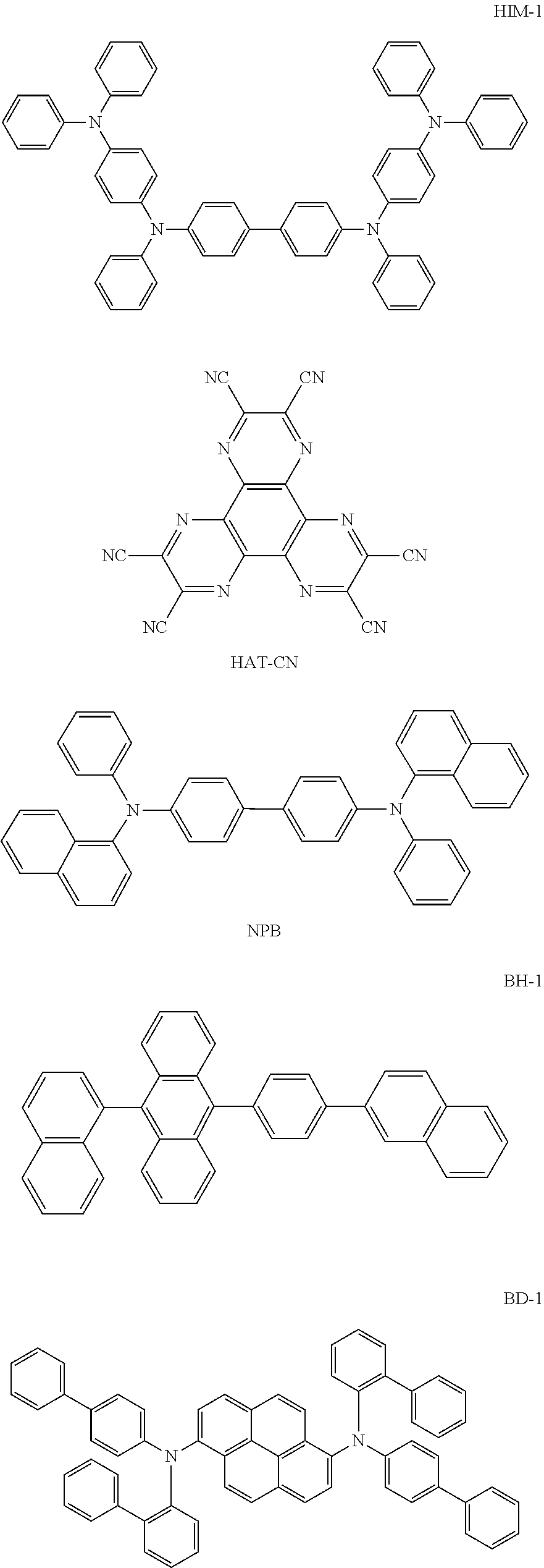

| TABLE 3 |
| Data of the luminescent property test of the organic electroluminescent devices |
| Driving voltage | Luminous efficiency | Lifetime | |||
| Material of light | [V] | [cd/A] | [T97, h] | ||
| No. | extraction layer | (@ 10 mA/cm2) | (@ 10 mA/cm2) | (@ 10 mA/cm2) | Color |
| Example 1 | Compound 1 | 3.98 | 6.82 | 123 | Blue |
| Example 2 | |
3.99 | 6.86 | 132 | Blue |
| Example 3 | Compound 22 | 4.00 | 6.84 | 150 | Blue |
| Example 4 | Compound 26 | 4.00 | 6.85 | 153 | Blue |
| Example 5 | Compound 27 | 4.00 | 6.85 | 152 | Blue |
| Example 6 | Compound 35 | 3.99 | 6.87 | 144 | Blue |
| Example 7 | Compound 41 | 3.99 | 6.83 | 130 | Blue |
| Example 8 | Compound 44 | 4.00 | 6.87 | 138 | Blue |
| Example 9 | Compound 73 | 4.02 | 6.81 | 129 | Blue |
| Example 10 | Compound 75 | 4.01 | 6.80 | 127 | Blue |
| Example 11 | Compound 78 | 4.02 | 6.85 | 135 | Blue |
| Example 12 | Compound 89 | 4.02 | 6.87 | 154 | Blue |
| Example 13 | Compound 101 | 4.00 | 6.82 | 120 | Blue |
| Example 14 | Compound 121 | 4.01 | 6.80 | 131 | Blue |
| Example 15 | Compound 125 | 4.01 | 6.84 | 138 | Blue |
| Example 16 | Compound 143 | 4.00 | 6.80 | 128 | Blue |
| Example 17 | Compound 144 | 4.03 | 6.82 | 120 | Blue |
| Example 18 | Compound 146 | 3.98 | 6.89 | 126 | Blue |
| Example 19 | Compound 153 | 3.99 | 6.88 | 131 | Blue |
| Comparative | CPM-1 | 4.01 | 6.85 | 95 | Blue |
| Example 1 | |||||
| Comparative | CPM-2 | 4.00 | 6.88 | 105 | Blue |
| Example 2 | |||||
| Comparative | — | 4.00 | 4.56 | 90 | Blue |
| Example 3 | |||||
Claims (7)


Applications Claiming Priority (2)
| Application Number | Priority Date | Filing Date | Title |
|---|---|---|---|
| CN201910631205.2 | 2019-07-12 | ||
| CN201910631205.2A CN110256358B (en) | 2019-07-12 | 2019-07-12 | Amine derivative and organic electroluminescent device thereof |
Publications (2)
| Publication Number | Publication Date |
|---|---|
| US20210009574A1 US20210009574A1 (en) | 2021-01-14 |
| US11725003B2 true US11725003B2 (en) | 2023-08-15 |
Family
ID=67925881
Family Applications (1)
| Application Number | Title | Priority Date | Filing Date |
|---|---|---|---|
| US16/848,401 Active 2041-07-14 US11725003B2 (en) | 2019-07-12 | 2020-04-14 | Amine derivative and an organic electroluminescent device thereof |
Country Status (7)
| Country | Link |
|---|---|
| US (1) | US11725003B2 (en) |
| EP (1) | EP3763707B1 (en) |
| JP (1) | JP6972226B2 (en) |
| KR (1) | KR102429199B1 (en) |
| CN (1) | CN110256358B (en) |
| ES (1) | ES2949041T3 (en) |
| PL (1) | PL3763707T3 (en) |
Families Citing this family (10)
| Publication number | Priority date | Publication date | Assignee | Title |
|---|---|---|---|---|
| CN110669025A (en) * | 2019-09-26 | 2020-01-10 | 吉林奥来德光电材料股份有限公司 | Aromatic amine compound, preparation method thereof and organic light-emitting device comprising aromatic amine compound |
| CN110964002A (en) * | 2019-12-13 | 2020-04-07 | 长春海谱润斯科技有限公司 | Arylamine derivative and organic light-emitting device thereof |
| CN111205237B (en) * | 2020-01-13 | 2020-12-29 | 长春海谱润斯科技股份有限公司 | Triamine derivative and organic electroluminescent device thereof |
| CN111785849B (en) * | 2020-07-14 | 2021-02-02 | 长春海谱润斯科技股份有限公司 | Top-emitting organic electroluminescent device with covering layer |
| CN111892586B (en) * | 2020-09-08 | 2021-08-24 | 长春海谱润斯科技股份有限公司 | Benzo five-membered N-containing heterocyclic heteroaryl amine compound and organic electroluminescent device thereof |
| CN111978329B (en) * | 2020-09-09 | 2023-04-07 | 烟台显华化工科技有限公司 | Compound, hole transport material, organic electroluminescent device and display device |
| WO2022100099A1 (en) * | 2020-11-13 | 2022-05-19 | 广州华睿光电材料有限公司 | Compound for organic electroluminescence device |
| CN113582938A (en) * | 2021-07-30 | 2021-11-02 | 上海天马有机发光显示技术有限公司 | Organic compound and application thereof |
| WO2023039010A1 (en) * | 2021-09-08 | 2023-03-16 | Academia Sinica | Compounds and their uses for treating neurodegenerative disease |
| CN113937233B (en) * | 2021-09-30 | 2024-04-02 | 武汉天马微电子有限公司 | Organic electroluminescent device and application thereof |
Citations (16)
| Publication number | Priority date | Publication date | Assignee | Title |
|---|---|---|---|---|
| US4769292A (en) * | 1987-03-02 | 1988-09-06 | Eastman Kodak Company | Electroluminescent device with modified thin film luminescent zone |
| EP0879868A2 (en) | 1997-05-19 | 1998-11-25 | Canon Kabushiki Kaisha | Organic compound and electroluminescent device using the same |
| JP2001106678A (en) | 1999-10-04 | 2001-04-17 | Chemiprokasei Kaisha Ltd | New heterocyclic ring-containing arylamine compound and organic electroluminescent element using the same |
| US20120001127A1 (en) | 2010-07-02 | 2012-01-05 | Plextronics, Inc. | Hole transport compositions and related devices and methods (i) |
| US20120330025A1 (en) | 2011-06-24 | 2012-12-27 | Semiconductor Energy Laboratory Co., Ltd. | Triarylamine Compound, Light-Emitting Element, Light-Emitting Device, Electronic Device, and Lighting Device |
| WO2013094951A1 (en) | 2011-12-23 | 2013-06-27 | 제일모직 주식회사 | Compound for organic optoelectronic device, organic light-emitting diode containing same, and display device comprising organic light-emitting diode |
| KR20130118811A (en) | 2012-04-20 | 2013-10-30 | 주식회사 엘지화학 | New compound and organic light emitting device using the same |
| TW201506128A (en) | 2013-07-03 | 2015-02-16 | Hodogaya Chemical Co Ltd | Organic electroluminescent device |
| CN104509211A (en) | 2012-06-12 | 2015-04-08 | 索尼公司 | Organic electroluminescent element and display device |
| CN107936955A (en) | 2017-12-05 | 2018-04-20 | 李现伟 | 7H benzos [de] anthracene class electroluminescent organic material, luminescent device and display |
| CN108047130A (en) | 2017-12-05 | 2018-05-18 | 李现伟 | Benzanthracenes electroluminescent organic material, luminescent device and display |
| CN108191744A (en) | 2017-12-05 | 2018-06-22 | 李现伟 | Benzfluorene class electroluminescent organic material, luminescent device and display |
| CN108203406A (en) | 2017-12-05 | 2018-06-26 | 李现伟 | Benzfluorene class electroluminescent organic material, luminescent device and display |
| CN109535012A (en) | 2018-12-17 | 2019-03-29 | 长春海谱润斯科技有限公司 | A kind of organic electroluminescence device |
| CN109574857A (en) | 2018-11-29 | 2019-04-05 | 长春海谱润斯科技有限公司 | A kind of organic electroluminescence device aromatic amine compound and its organic electroluminescence device |
| CN110669025A (en) * | 2019-09-26 | 2020-01-10 | 吉林奥来德光电材料股份有限公司 | Aromatic amine compound, preparation method thereof and organic light-emitting device comprising aromatic amine compound |
Family Cites Families (3)
| Publication number | Priority date | Publication date | Assignee | Title |
|---|---|---|---|---|
| JP3508984B2 (en) * | 1997-05-19 | 2004-03-22 | キヤノン株式会社 | Organic compound and light emitting device using the organic compound |
| KR101226700B1 (en) | 2009-08-21 | 2013-01-25 | 에스에프씨 주식회사 | Amine derivatives and organoelectroluminescent device employing the same |
| KR102641712B1 (en) * | 2019-06-24 | 2024-02-27 | 덕산네오룩스 주식회사 | Organic electric device |
-
2019
- 2019-07-12 CN CN201910631205.2A patent/CN110256358B/en active Active
-
2020
- 2020-03-24 KR KR1020200035608A patent/KR102429199B1/en active IP Right Grant
- 2020-03-30 ES ES20166566T patent/ES2949041T3/en active Active
- 2020-03-30 PL PL20166566.8T patent/PL3763707T3/en unknown
- 2020-03-30 EP EP20166566.8A patent/EP3763707B1/en active Active
- 2020-04-14 US US16/848,401 patent/US11725003B2/en active Active
- 2020-04-28 JP JP2020079126A patent/JP6972226B2/en active Active
Patent Citations (18)
| Publication number | Priority date | Publication date | Assignee | Title |
|---|---|---|---|---|
| US4769292A (en) * | 1987-03-02 | 1988-09-06 | Eastman Kodak Company | Electroluminescent device with modified thin film luminescent zone |
| EP0879868A2 (en) | 1997-05-19 | 1998-11-25 | Canon Kabushiki Kaisha | Organic compound and electroluminescent device using the same |
| JP2001106678A (en) | 1999-10-04 | 2001-04-17 | Chemiprokasei Kaisha Ltd | New heterocyclic ring-containing arylamine compound and organic electroluminescent element using the same |
| US20120001127A1 (en) | 2010-07-02 | 2012-01-05 | Plextronics, Inc. | Hole transport compositions and related devices and methods (i) |
| CN107068914A (en) | 2010-07-02 | 2017-08-18 | 索尔维美国有限公司 | Hole transport composition and related device and method (I) |
| US20120330025A1 (en) | 2011-06-24 | 2012-12-27 | Semiconductor Energy Laboratory Co., Ltd. | Triarylamine Compound, Light-Emitting Element, Light-Emitting Device, Electronic Device, and Lighting Device |
| WO2013094951A1 (en) | 2011-12-23 | 2013-06-27 | 제일모직 주식회사 | Compound for organic optoelectronic device, organic light-emitting diode containing same, and display device comprising organic light-emitting diode |
| KR20130118811A (en) | 2012-04-20 | 2013-10-30 | 주식회사 엘지화학 | New compound and organic light emitting device using the same |
| CN104509211A (en) | 2012-06-12 | 2015-04-08 | 索尼公司 | Organic electroluminescent element and display device |
| EP2861044A1 (en) | 2012-06-12 | 2015-04-15 | Sony Corporation | Organic electroluminescent element and display device |
| TW201506128A (en) | 2013-07-03 | 2015-02-16 | Hodogaya Chemical Co Ltd | Organic electroluminescent device |
| CN107936955A (en) | 2017-12-05 | 2018-04-20 | 李现伟 | 7H benzos [de] anthracene class electroluminescent organic material, luminescent device and display |
| CN108047130A (en) | 2017-12-05 | 2018-05-18 | 李现伟 | Benzanthracenes electroluminescent organic material, luminescent device and display |
| CN108191744A (en) | 2017-12-05 | 2018-06-22 | 李现伟 | Benzfluorene class electroluminescent organic material, luminescent device and display |
| CN108203406A (en) | 2017-12-05 | 2018-06-26 | 李现伟 | Benzfluorene class electroluminescent organic material, luminescent device and display |
| CN109574857A (en) | 2018-11-29 | 2019-04-05 | 长春海谱润斯科技有限公司 | A kind of organic electroluminescence device aromatic amine compound and its organic electroluminescence device |
| CN109535012A (en) | 2018-12-17 | 2019-03-29 | 长春海谱润斯科技有限公司 | A kind of organic electroluminescence device |
| CN110669025A (en) * | 2019-09-26 | 2020-01-10 | 吉林奥来德光电材料股份有限公司 | Aromatic amine compound, preparation method thereof and organic light-emitting device comprising aromatic amine compound |
Non-Patent Citations (6)
| Title |
|---|
| European Search Report dated Oct. 5, 2020 in EP Patent Application No. 20166566.8, pp. 1-6. |
| Liao, Y.L., et al., "A Novel Ambipolar Spirobifluorene Derivative that Behaves as an Efficient Blue-Light Emitter in Organic Light-Emitting Diodes", In Organic Letters, vol. 9, No. 22, Aug. 15, 2007, pp. 4511-4514. |
| Office Action dated May 24, 2021 in JP Patent Application No. 2020-079126, pp. 1-6. |
| Office Action dated Nov. 13, 2019 in CN Patent Application No. 201910631205.2. |
| Ran, X.Q., et al., "Theoretical Study on Photophysical Properties of Ambipolar Spirobifluorene Derivatives as Efficient Blue-Light-Emitting Materials", In J. Phys. Chem. A, vol. 113, May 23, 2009, pp. 7933-7939. |
| Saragi, T.P.I., et al., "Spiro Compounds for Organic Optoelectronics", In Chem. Rev., vol. 107, Mar. 24, 2007, pp. 1011-1065. |
Also Published As
| Publication number | Publication date |
|---|---|
| EP3763707A1 (en) | 2021-01-13 |
| JP2021014444A (en) | 2021-02-12 |
| KR20210007817A (en) | 2021-01-20 |
| US20210009574A1 (en) | 2021-01-14 |
| PL3763707T3 (en) | 2023-10-09 |
| CN110256358A (en) | 2019-09-20 |
| CN110256358B (en) | 2020-03-17 |
| ES2949041T3 (en) | 2023-09-25 |
| EP3763707B1 (en) | 2023-05-03 |
| JP6972226B2 (en) | 2021-11-24 |
| KR102429199B1 (en) | 2022-08-04 |
Similar Documents
| Publication | Publication Date | Title |
|---|---|---|
| US11725003B2 (en) | Amine derivative and an organic electroluminescent device thereof | |
| US11706943B2 (en) | Organic electroluminescent element and method for producing same | |
| US10797245B2 (en) | Compound for organic optoelectronic element, organic optoelectronic element, and display device | |
| US9732036B2 (en) | Compound having carbazole ring structure, and organic electroluminescent device | |
| US9082986B2 (en) | Organic electroluminescent element | |
| US9306174B2 (en) | Organic electroluminescent device | |
| US20120319091A1 (en) | Aromatic amine derivative, and organic electroluminescent element comprising same | |
| US20210277026A1 (en) | Polycyclic compound and organic light-emitting device comprising same | |
| US9299935B2 (en) | Nitrogen-containing heterocyclic compounds and organic electronic device comprising the same | |
| US20220209132A1 (en) | Heterocyclic compound and organic electroluminescent device comprising same | |
| WO2020151500A1 (en) | Organic electroluminescent compound, electroluminescent material and organic electroluminescent device | |
| US10326079B2 (en) | Organic electroluminescent device | |
| US20220077410A1 (en) | Compound and organic light-emitting device comprising same | |
| US20210217963A1 (en) | Organic light-emitting device | |
| US10516113B2 (en) | Organic compound, organic optoelectric device and display device | |
| US20200303663A1 (en) | Condensed-cyclic compound and organic light-emitting device including the same | |
| US20200266360A1 (en) | Condensed cyclic compound and organic light-emitting device including the same | |
| CN114394949A (en) | Biphenylamine derivative and organic electroluminescent device thereof | |
| CN114907217A (en) | Triamine compound and organic electroluminescent device thereof | |
| US11453682B2 (en) | Condensed-cyclic compound and organic light-emitting device including the same | |
| CN113666921A (en) | Heterocyclic compound and organic electroluminescent device thereof | |
| CN115448870B (en) | Arylamine compound containing carbazole group and organic electroluminescent device thereof | |
| US20230080626A1 (en) | Condensed cyclic compound, organic light-emitting device including the same, and electronic apparatus including the organic light-emitting device | |
| US20230171979A1 (en) | Organic light emitting diode and organic light emitting device having thereof | |
| US20230301179A1 (en) | Heterocyclic compound, organic light-emitting device including the same, and electronic apparatus including the organic light-emitting device |
Legal Events
| Date | Code | Title | Description |
|---|---|---|---|
| FEPP | Fee payment procedure |
Free format text: ENTITY STATUS SET TO UNDISCOUNTED (ORIGINAL EVENT CODE: BIG.); ENTITY STATUS OF PATENT OWNER: SMALL ENTITY |
|
| FEPP | Fee payment procedure |
Free format text: ENTITY STATUS SET TO SMALL (ORIGINAL EVENT CODE: SMAL); ENTITY STATUS OF PATENT OWNER: SMALL ENTITY |
|
| STPP | Information on status: patent application and granting procedure in general |
Free format text: APPLICATION DISPATCHED FROM PREEXAM, NOT YET DOCKETED |
|
| AS | Assignment |
Owner name: CHANGCHUN HYPERIONS TECHNOLOGY CO., LTD, CHINA Free format text: CHANGE OF NAME;ASSIGNOR:CHANGCHUN HYPERIONS SCIENTIFIC CO., LTD;REEL/FRAME:054483/0585 Effective date: 20200912 |
|
| STPP | Information on status: patent application and granting procedure in general |
Free format text: DOCKETED NEW CASE - READY FOR EXAMINATION |
|
| STPP | Information on status: patent application and granting procedure in general |
Free format text: NON FINAL ACTION MAILED |
|
| STPP | Information on status: patent application and granting procedure in general |
Free format text: RESPONSE TO NON-FINAL OFFICE ACTION ENTERED AND FORWARDED TO EXAMINER |
|
| STPP | Information on status: patent application and granting procedure in general |
Free format text: PUBLICATIONS -- ISSUE FEE PAYMENT VERIFIED |
|
| STCF | Information on status: patent grant |
Free format text: PATENTED CASE |