US11716836B2 - Electromagnetic compatibility gasket and vent - Google Patents

Electromagnetic compatibility gasket and vent Download PDF

Info

Publication number
US11716836B2
US11716836B2 US17/369,387 US202117369387A US11716836B2 US 11716836 B2 US11716836 B2 US 11716836B2 US 202117369387 A US202117369387 A US 202117369387A US 11716836 B2 US11716836 B2 US 11716836B2
Authority
US
United States
Prior art keywords
chassis
emi gasket
emi
gasket
electronic device
Prior art date
Legal status (The legal status is an assumption and is not a legal conclusion. Google has not performed a legal analysis and makes no representation as to the accuracy of the status listed.)
Active, expires
Application number
US17/369,387
Other versions
US20210337707A1 (en
Inventor
Vic Hong Chia
George Edward Curtis
John David Stallings
Current Assignee (The listed assignees may be inaccurate. Google has not performed a legal analysis and makes no representation or warranty as to the accuracy of the list.)
Cisco Technology Inc
Original Assignee
Cisco Technology Inc
Priority date (The priority date is an assumption and is not a legal conclusion. Google has not performed a legal analysis and makes no representation as to the accuracy of the date listed.)
Filing date
Publication date
Application filed by Cisco Technology Inc filed Critical Cisco Technology Inc
Priority to US17/369,387 priority Critical patent/US11716836B2/en
Assigned to CISCO TECHNOLOGY, INC. reassignment CISCO TECHNOLOGY, INC. ASSIGNMENT OF ASSIGNORS INTEREST (SEE DOCUMENT FOR DETAILS). Assignors: CHIA, VIC HONG, CURTIS, GEORGE EDWARD, STALLINGS, JOHN DAVID
Publication of US20210337707A1 publication Critical patent/US20210337707A1/en
Application granted granted Critical
Publication of US11716836B2 publication Critical patent/US11716836B2/en
Active legal-status Critical Current
Adjusted expiration legal-status Critical

Links

Images

Classifications

    • HELECTRICITY
    • H05ELECTRIC TECHNIQUES NOT OTHERWISE PROVIDED FOR
    • H05KPRINTED CIRCUITS; CASINGS OR CONSTRUCTIONAL DETAILS OF ELECTRIC APPARATUS; MANUFACTURE OF ASSEMBLAGES OF ELECTRICAL COMPONENTS
    • H05K9/00Screening of apparatus or components against electric or magnetic fields
    • H05K9/0007Casings
    • H05K9/0015Gaskets or seals
    • H05K9/0016Gaskets or seals having a spring contact
    • HELECTRICITY
    • H05ELECTRIC TECHNIQUES NOT OTHERWISE PROVIDED FOR
    • H05KPRINTED CIRCUITS; CASINGS OR CONSTRUCTIONAL DETAILS OF ELECTRIC APPARATUS; MANUFACTURE OF ASSEMBLAGES OF ELECTRICAL COMPONENTS
    • H05K9/00Screening of apparatus or components against electric or magnetic fields
    • H05K9/0007Casings
    • H05K9/0015Gaskets or seals
    • HELECTRICITY
    • H05ELECTRIC TECHNIQUES NOT OTHERWISE PROVIDED FOR
    • H05KPRINTED CIRCUITS; CASINGS OR CONSTRUCTIONAL DETAILS OF ELECTRIC APPARATUS; MANUFACTURE OF ASSEMBLAGES OF ELECTRICAL COMPONENTS
    • H05K1/00Printed circuits
    • H05K1/02Details
    • H05K1/0213Electrical arrangements not otherwise provided for
    • H05K1/0216Reduction of cross-talk, noise or electromagnetic interference
    • HELECTRICITY
    • H05ELECTRIC TECHNIQUES NOT OTHERWISE PROVIDED FOR
    • H05KPRINTED CIRCUITS; CASINGS OR CONSTRUCTIONAL DETAILS OF ELECTRIC APPARATUS; MANUFACTURE OF ASSEMBLAGES OF ELECTRICAL COMPONENTS
    • H05K5/00Casings, cabinets or drawers for electric apparatus
    • H05K5/02Details
    • H05K5/0217Mechanical details of casings
    • HELECTRICITY
    • H05ELECTRIC TECHNIQUES NOT OTHERWISE PROVIDED FOR
    • H05KPRINTED CIRCUITS; CASINGS OR CONSTRUCTIONAL DETAILS OF ELECTRIC APPARATUS; MANUFACTURE OF ASSEMBLAGES OF ELECTRICAL COMPONENTS
    • H05K5/00Casings, cabinets or drawers for electric apparatus
    • H05K5/02Details
    • H05K5/0247Electrical details of casings, e.g. terminals, passages for cables or wiring
    • HELECTRICITY
    • H05ELECTRIC TECHNIQUES NOT OTHERWISE PROVIDED FOR
    • H05KPRINTED CIRCUITS; CASINGS OR CONSTRUCTIONAL DETAILS OF ELECTRIC APPARATUS; MANUFACTURE OF ASSEMBLAGES OF ELECTRICAL COMPONENTS
    • H05K7/00Constructional details common to different types of electric apparatus
    • H05K7/20Modifications to facilitate cooling, ventilating, or heating
    • H05K7/20009Modifications to facilitate cooling, ventilating, or heating using a gaseous coolant in electronic enclosures
    • H05K7/20136Forced ventilation, e.g. by fans
    • H05K7/20172Fan mounting or fan specifications
    • GPHYSICS
    • G06COMPUTING; CALCULATING OR COUNTING
    • G06FELECTRIC DIGITAL DATA PROCESSING
    • G06F1/00Details not covered by groups G06F3/00 - G06F13/00 and G06F21/00
    • G06F1/16Constructional details or arrangements
    • G06F1/18Packaging or power distribution
    • G06F1/181Enclosures
    • G06F1/182Enclosures with special features, e.g. for use in industrial environments; grounding or shielding against radio frequency interference [RFI] or electromagnetical interference [EMI]
    • HELECTRICITY
    • H05ELECTRIC TECHNIQUES NOT OTHERWISE PROVIDED FOR
    • H05KPRINTED CIRCUITS; CASINGS OR CONSTRUCTIONAL DETAILS OF ELECTRIC APPARATUS; MANUFACTURE OF ASSEMBLAGES OF ELECTRICAL COMPONENTS
    • H05K2201/00Indexing scheme relating to printed circuits covered by H05K1/00
    • H05K2201/20Details of printed circuits not provided for in H05K2201/01 - H05K2201/10
    • H05K2201/2036Permanent spacer or stand-off in a printed circuit or printed circuit assembly

Definitions

  • the present disclosure relates to cooling and electromagnetic compatibility of electronic devices.
  • Chassis-mounted electronic devices such as network equipment, typically bring a large number of electronic devices in close proximity, which may lead to issues with heat management and Electro-Magnetic Interference (EMI) management.
  • EMI Electro-Magnetic Interference
  • the heat generated by the chassis-mounted electronic devices is typically managed by drawings cooling air through the chassis, which is most effective with large open spaces in the chassis.
  • EMI management relies on the chassis providing a Faraday cage to contain stray electromagnetic emitted from the electronic devices in the chassis, which is compromised by large openings in the chassis.
  • FIG. 1 is a diagram of an electronic device configured with an EMI gasket, according to an example embodiment.
  • FIG. 2 is a side view of an electronic device that illustrates the airflow through the device, according to an example embodiment.
  • FIG. 3 A illustrates an EMI gasket that enables increased airflow, according to an example embodiment.
  • FIGS. 3 B and 3 C show cross-sectional views of an EMI gasket, according to example embodiments.
  • FIG. 4 illustrates the attachment of an upper EMI gasket to an upper chassis, according to an example embodiment.
  • FIG. 5 illustrates the attachment of a lower EMI gasket to a lower chassis, according to an example embodiment.
  • FIG. 6 is a flowchart illustrating operations for assembling an electronic device in a chassis with EMI gaskets, according to an example embodiment.
  • an apparatus comprising a chassis, an upper EMI gasket, and a lower EMI gasket.
  • the chassis comprises an upper chassis and a lower chassis that are constructed from a conductive sheet with a first thickness.
  • the upper chassis and the lower chassis are coupled to form an interior of the chassis housing an electronic device.
  • the upper EMI gasket is attached to the upper chassis, and has a second thickness that is less than the first thickness.
  • the upper EMI gasket includes perforations to allow cooling air through the upper EMI gasket and into the interior of the chassis.
  • the lower EMI gasket is attached to the lower chassis, and also has a second thickness that is less than the first thickness.
  • the lower EMI gasket includes perforations to allow cooling air through the lower EMI gasket and into the interior of the chassis.
  • Both the upper EMI gasket and the lower EMI gasket are configured to resiliently contact a portion of the electronic device to provide EMI shielding for the electronic device.
  • a manual assembly line presents a challenge to lowering the unit cost of high volume manufacturing due to the overhead burden and quality issues, such as human error.
  • Automation of an assembly line aims to mitigate human factors in the assembly line to reduce the unit cost in a high volume manufacturing environment.
  • the techniques described herein enable increased automation in the assembly of chassis-mounted electronic devices by reducing the complexity of the assembly process (e.g., replacing complex placement of components in favor of linear pick and place motion).
  • the network device 100 includes electronics 110 that are enclosed within the chassis 120 and ports 115 that provide access to the enclosed electronics 110 from outside the chassis 120 .
  • the chassis 120 has made transparent for clarity in depicting additional portions of the network device 100 .
  • An upper Electro-Magnetic Interference (EMI) gasket 130 is shown that connects the frame of the ports 115 to the chassis.
  • a lower EMI gasket 140 also connects the frame of the ports 115 to the chassis.
  • the upper EMI gasket and the lower EMI gasket 140 include perforations that allow cooling air to enter the chassis 120 above and below the ports 115 .
  • Bolts 150 securely connect the portions of the network device 100 within the chassis 120 .
  • a Faraday cage encloses the electronics 110 and mitigates stray electromagnetic radiation from the electronics 110 .
  • the chassis 120 may be split into an upper chassis and a lower chassis that are fastened together to provide structural support for the electronics 110 .
  • the chassis 120 may be manufactured from sheets of conductive material (e.g., stainless steel) to form a portion of a Faraday cage providing EMI shielding for the electronics 110 .
  • the chassis 120 may include standoffs to support one or more boards of the electronics 110 or other components housed within the chassis 120 .
  • the material of the sheet(s) forming the chassis 120 is of sufficient thickness (e.g., 2 mm of stainless steel) to provide structural support for the network device 100 .
  • the upper EMI gasket 130 and the lower EMI gasket 140 may be manufactured from a sheet of relatively thin conductive material (e.g., 0.25 mm of stainless steel) in comparison to the sheet material forming the chassis 120 . Perforations may be stamped into the upper EMI gasket 130 and the lower EMI gasket 140 to allow cooling air to flow into the interior of the chassis 120 .
  • the upper EMI gasket 130 and the lower EMI gasket 140 may also be curved to provide a spring resilience between the chassis 120 and the frame of the ports 115 when the chassis 120 is assembled.
  • FIG. 2 a side view of the network device 100 is shown with an example of the airflow through the interior of the chassis 120 cooling the electronics 110 .
  • a portion of the electronics 110 are disposed on a main board 210 enclosed completely by the chassis 120 .
  • Another portion of the electronics 110 are disposed on a daughtercard 220 that includes the ports 115 .
  • a fan 230 draws air through the upper EMI gasket 130 and the lower EMI gasket 140 into the interior of the chassis 120 .
  • the magnified portion of FIG. 2 illustrates specific features of the chassis support and airflow through the front of the network device 100 .
  • the chassis 120 includes an upper standoff 240 and a lower standoff 245 that are configured to position the ports 115 on the daughtercard 220 to allow airflow above and below the daughtercard 220 .
  • the upper standoff 240 is manufactured from the same material as the upper component of the chassis 120 .
  • the lower standoff 245 may be manufactured from the same material as the lower component of the chassis 120 .
  • the upper EMI gasket 130 and the lower EMI gasket 140 (shown in cross-section in FIG. 2 ) are curved to allow the air to flow through the EMI gaskets in multiple locations and directions.
  • the curved-cross section of the EMI gaskets also provides a spring force to ensure good electrical contact between the chassis 120 and the frame surrounding the ports 115 .
  • the main board 210 may be positioned away from the front of the network device 100 to prevent the main board 210 from constricting the air flowing through the lower EMI gasket 140 .
  • the EMI gasket 300 may be the upper EMI gasket 130 or the lower EMI gasket 140 , as shown in FIG. 1 and FIG. 2 .
  • the EMI gasket 300 includes perforations 310 separated by a web 320 of metal.
  • the EMI gasket 300 also includes fingers 330 configured to contact the frame of the electronics extending out of the chassis (e.g., ports 115 ) at multiple points to ensure good electrical contact along the length of the EMI gasket 300 .
  • the EMI gasket 300 further includes at least one space 340 to allow a connecting bolt (e.g., bolt 150 shown in FIG. 1 ) to secure the chassis in place around the electronic components.
  • the EMI gasket 300 may be manufactured by punching the perforations 310 from a thin metal strip.
  • the width of the web 320 is constrained by the thickness of the base sheet metal to ensure the integrity of the finished product.
  • the web 320 may be constrained to being approximately twice the thickness of the sheet metal.
  • the EMI gasket 300 may be made from a sheet metal that is sufficiently thin to allow the perforations 310 to cover at least 90% of the EMI gasket 300 .
  • the chassis provides structural support for the entire device, and is manufactured from thicker sheet metal. The thinner sheet metal of the EMI gasket enables a thinner web 320 than an array of vent holes punched into the chassis itself, and allows for a greater surface area to be covered with perforations 310 .
  • the EMI gasket 300 is curved to provide a spring resilience between the chassis (e.g., chassis 120 ) and the frame of the electronics extending out of the chassis (e.g., ports 115 ).
  • the curve in the EMI gasket may be discrete or continuous, and may include convex or concave shapes.
  • FIG. 3 B shows a cross-sectional view of one example of the curve in the EMI gasket 300 .
  • FIG. 3 C shows a cross-sectional view of another example of a more complex curve in the EMI gasket 300 .
  • the curve in the upper EMI gasket 130 may be different than the curve in the lower EMI gasket 140 .
  • the two EMI gaskets may have the same cross-sectional curve.
  • FIG. 4 an example of pre-mounting the upper EMI gasket 130 on the chassis is shown.
  • the upper EMI gasket 130 is attached to an upper chassis 410 .
  • the upper chassis 410 includes standoffs 420 that position the electronics that extend out of the chassis (e.g., ports 115 shown in FIG. 1 ).
  • the upper EMI gasket 130 is fastened to the upper chassis 410 through the standoffs 420 .
  • the standoffs 420 include a slot 430 that matches a locking tab 440 that is formed on the upper EMI gasket 130 . Additional support for the upper EMI gasket 130 is provided by fingers 450 , which are part of the upper chassis 410 .
  • FIG. 5 an example of pre-mounting the lower EMI gasket 140 on a lower chassis 510 is shown.
  • the lower EMI gasket 140 is placed on the lower chassis 510 and held in place by a chassis bracket 520 .
  • the chassis bracket 520 includes standoffs 530 that position the electronics that extend out of the chassis (e.g., ports 115 shown in FIG. 1 ).
  • a swaged connection 540 fastens the chassis bracket 520 to the lower chassis 510 and secures the lower EMI gasket 140 between the chassis bracket 520 and the lower chassis 510 .
  • Combining the upper chassis 410 shown in FIG. 4 (i.e., pre-mounted with the upper EMI gasket 130 ) with the lower chassis 510 shown in FIG. 5 (i.e., pre-mounted with the lower EMI gasket 140 ) enables a simplified assembly process of the network device shown in FIG. 1 .
  • the final assembly of the chassis may be completed with pick and place automation. This automation removes human factors and leads to higher quality and lower unit cost of the electronic device.
  • an electronic device is mounted on a lower chassis constructed of a conductive sheet of a first thickness.
  • the lower chassis is constructed primarily from a stainless steel sheet that is approximately 2 mm thick.
  • the lower chassis may be constructed from other materials (e.g., aluminum) with a range of thicknesses (e.g., 1-5 mm) that is sufficient to provide structural support to the electronic device.
  • a lower EMI gasket is attached to the lower chassis.
  • the lower EMI gasket has a second thickness that is less than the first thickness.
  • the lower EMI gasket may be constructed from a sheet of stainless steel that is approximately 0.25 mm thick.
  • the lower EMI gasket includes perforations to allow cooling air through the lower EMI gasket. In one example, the perforations cover at least 90% of the lower EMI gasket to ensure sufficient airflow to cool the electronic device.
  • an upper EMI gasket is attached to an upper chassis.
  • the upper chassis has a first thickness to provide structural support for the assembled electronic device.
  • the upper chassis is constructed primarily from a stainless steel sheet that is approximately 2 mm thick.
  • the upper chassis may be constructed from other materials (e.g., aluminum) with a range of thicknesses (e.g., 1-5 mm) that is sufficient to provide structural support to the electronic device.
  • the upper EMI gasket has a second thickness that is less than the first thickness.
  • the upper EMI gasket may be constructed from a sheet of stainless steel that is approximately 0.25 mm thick.
  • the upper EMI gasket includes perforations to allow cooling air through the upper EMI gasket. In one example, the perforations cover at least 90% of the upper EMI gasket to ensure sufficient airflow to cool the electronic device.
  • the upper chassis and the lower chassis are coupled together to enclose the electronic device.
  • the upper EMI gasket and the lower EMI gasket are configured to resiliently contact a portion of the electronic device to provide EMI shielding for the electronic device, while allowing cooling air to pass through the perforations in the upper EMI gasket and the lower EMI gasket.
  • the upper chassis and lower chassis are connected by bolts that are electrically connected to the upper EMI gasket and the lower EMI gasket.
  • the bolts connecting the upper chassis and the lower chassis may be conductive to provide further EMI shielding to the electronic device.
  • the techniques presented herein provide a system layout that maximizes airflow through EMI gaskets to achieve maximum cooling while providing EMI isolation.
  • the increased airflow disrupts the need for exotic thermal solutions (e.g., designed heat sinks, expensive/complex faceplate design, high performance fans) to provide additional cooling as ASIC components evolve in density and heat production.
  • the techniques enable the reuse of common components (e.g., heatsinks, fans, etc.) from legacy platforms to the latest generation platform, which directly translates to higher volume production at a lower unit cost.
  • the overall system layout of top down linear integration sequences enable the deployment of robotic automation to improve quality and lower labor dependence, resulting in lower unit costs.
  • the EMI gasket design provides continuous effective contact between the metal chassis and the metal frame of ports extending from the chassis, while providing increased airflow through the perforations covering at least 90% of the EMI gasket.
  • the EMI gasket provides a cost effective solution that targets multiple challenges, such as cooling, EMI shielding, design for cost, design for automation and quality in high volume system production.
  • an apparatus comprising a chassis, an upper EMI gasket, and a lower EMI gasket.
  • the chassis comprises an upper chassis and a lower chassis that are constructed from a conductive sheet with a first thickness.
  • the upper chassis and the lower chassis are coupled to form an interior of the chassis housing an electronic device.
  • the upper EMI gasket is attached to the upper chassis, and has a second thickness that is less than the first thickness.
  • the upper EMI gasket includes perforations to allow cooling air through the upper EMI gasket and into the interior of the chassis.
  • the lower EMI gasket is attached to the lower chassis, and also has a second thickness that is less than the first thickness.
  • the lower EMI gasket includes perforations to allow cooling air through the lower EMI gasket and into the interior of the chassis.
  • Both the upper EMI gasket and the lower EMI gasket are configured to resiliently contact a portion of the electronic device to provide EMI shielding for the electronic device.
  • a system comprising a chassis, an electronic device, a fan, an upper EMI gasket, and a lower EMI gasket.
  • the chassis comprises an upper chassis and a lower chassis that are constructed from a conductive sheet with a first thickness.
  • the electronic device comprises a motherboard disposed in the interior of the chassis and a daughterboard including a plurality of ports accessible from outside the chassis.
  • the upper chassis and the lower chassis are coupled to form an interior of the chassis housing an electronic device.
  • the fan is configured to draw cooling air into the interior of the chassis and cool the electronic device.
  • the upper EMI gasket is attached to the upper chassis, and has a second thickness that is less than the first thickness.
  • the upper EMI gasket includes perforations to allow the cooling air through the upper EMI gasket and into the interior of the chassis.
  • the lower EMI gasket is attached to the lower chassis, and also has a second thickness that is less than the first thickness.
  • the lower EMI gasket includes perforations to allow the cooling air through the lower EMI gasket and into the interior of the chassis. Both the upper EMI gasket and the lower EMI gasket are configured to resiliently contact the daughterboard to provide EMI shielding for the electronic device.
  • a method for assembling an electronic device within a chassis includes mounting the electronic device on a lower chassis constructed of a conductive sheet of a first thickness.
  • the method also includes attaching a lower EMI gasket to the lower chassis.
  • the lower EMI gasket has a second thickness that is less than the first thickness.
  • the lower EMI gasket also includes perforations to allow cooling air through the lower EMI gasket.
  • the method further includes attaching an upper EMI gasket having a second thickness to an upper chassis having a first thickness.
  • the upper EMI gasket also includes perforations to allow cooling air through the upper EMI gasket.
  • the method also includes coupling the upper chassis to the lower chassis to enclose the electronic device. When coupling the upper chassis and the lower chassis, the upper EMI gasket and the lower EMI gasket are configured to resiliently contact a portion of the electronic device to provide EMI shielding for the electronic device.

Abstract

A chassis-mounted electronic device includes a conductive chassis, an upper EMI gasket, and a lower EMI gasket. An upper chassis and a lower chassis of the conductive chassis are coupled to form an interior of the chassis housing an electronic device. The upper EMI gasket is attached to the upper chassis, and resiliently contacts a portion of the electronic device. The lower EMI gasket is attached to the lower chassis, and resiliently contacts a different portion of the electronic device. The upper and lower EMI gaskets include perforations to allow cooling air through the EMI gaskets and into the interior of the chassis. The conductive chassis, the upper EMI gasket, and the lower EMI gasket provide EMI shielding for the electronic device.

Description

CROSS-REFERENCE TO RELATED APPLICATIONS
This application is a continuation of U.S. application Ser. No. 16/826,557, filed Mar. 23, 2020, the entirety of which is hereby incorporated by reference herein.
TECHNICAL FIELD
The present disclosure relates to cooling and electromagnetic compatibility of electronic devices.
BACKGROUND
Chassis-mounted electronic devices, such as network equipment, typically bring a large number of electronic devices in close proximity, which may lead to issues with heat management and Electro-Magnetic Interference (EMI) management. The heat generated by the chassis-mounted electronic devices is typically managed by drawings cooling air through the chassis, which is most effective with large open spaces in the chassis. In contrast, EMI management relies on the chassis providing a Faraday cage to contain stray electromagnetic emitted from the electronic devices in the chassis, which is compromised by large openings in the chassis.
BRIEF DESCRIPTION OF THE DRAWINGS
FIG. 1 is a diagram of an electronic device configured with an EMI gasket, according to an example embodiment.
FIG. 2 is a side view of an electronic device that illustrates the airflow through the device, according to an example embodiment.
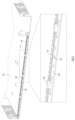
FIG. 3A illustrates an EMI gasket that enables increased airflow, according to an example embodiment.
FIGS. 3B and 3C show cross-sectional views of an EMI gasket, according to example embodiments.
FIG. 4 illustrates the attachment of an upper EMI gasket to an upper chassis, according to an example embodiment.
FIG. 5 illustrates the attachment of a lower EMI gasket to a lower chassis, according to an example embodiment.
FIG. 6 is a flowchart illustrating operations for assembling an electronic device in a chassis with EMI gaskets, according to an example embodiment.
DESCRIPTION OF EXAMPLE EMBODIMENTS
Overview
In one form, an apparatus is provided comprising a chassis, an upper EMI gasket, and a lower EMI gasket is provided. The chassis comprises an upper chassis and a lower chassis that are constructed from a conductive sheet with a first thickness. The upper chassis and the lower chassis are coupled to form an interior of the chassis housing an electronic device. The upper EMI gasket is attached to the upper chassis, and has a second thickness that is less than the first thickness. The upper EMI gasket includes perforations to allow cooling air through the upper EMI gasket and into the interior of the chassis. The lower EMI gasket is attached to the lower chassis, and also has a second thickness that is less than the first thickness. The lower EMI gasket includes perforations to allow cooling air through the lower EMI gasket and into the interior of the chassis. Both the upper EMI gasket and the lower EMI gasket are configured to resiliently contact a portion of the electronic device to provide EMI shielding for the electronic device.
Example Embodiments
As the market for chassis-mounted electronic devices, such as network switches and routers, progresses into producing higher volumes, the landscape for providing an enterprise switch moves from simply providing performance and features to incorporating a measure of value and cost. In a high volume manufacturing environment, a relatively small cost to add a feature to a single unit can lead to significant costs when multiplied over a yearlong manufacturing run. Leveraging and reusing common units, such as fans, heatsinks, and power supplies, may provide cost savings, but indirectly lead to a thermal bottleneck when a system is upgraded with a next generation, high heat flux Application Specific Integrated Circuit (ASIC). In addition to generating additional heat, smaller and denser ASICs may have stricter constraints on a maximum long-term temperature. The combination of denser ASICs and the reuse of common units designed for previous generations lead to thermal challenges. The techniques described herein provide for increased airflow to deal with the increased heat in a cost effective manner, rather than redesigning the commonly used fan units or applying exotic heat sink solutions.
Additionally, a manual assembly line presents a challenge to lowering the unit cost of high volume manufacturing due to the overhead burden and quality issues, such as human error. Automation of an assembly line aims to mitigate human factors in the assembly line to reduce the unit cost in a high volume manufacturing environment. The techniques described herein enable increased automation in the assembly of chassis-mounted electronic devices by reducing the complexity of the assembly process (e.g., replacing complex placement of components in favor of linear pick and place motion).
Existing solutions for increasing the airflow through a chassis-mounted electronic device (e.g., slanting the faceplate of the chassis to provide more vent holes, precision machining to increase the percentage of the front faceplate that can open for vent holes, or directing airflow through larger openings in the faceplate and additional smaller vent holes within the chassis) present additional constraints in cost and ease of manufacturing. Exotic solutions to thermal management (e.g., vapor chambers or three dimensional heat pipes) typically raise the cost of producing the chassis-mounted device to unprofitable levels.
Referring now to FIG. 1 , a chassis-mounted network device 100 is shown. Though the figures presented herein describe a network device, any chassis-mounted electronic device may benefit from the techniques described herein, and the specific embodiment of a chassis-mounted network device is used as an example. The network device 100 includes electronics 110 that are enclosed within the chassis 120 and ports 115 that provide access to the enclosed electronics 110 from outside the chassis 120.
In the magnified portion of FIG. 1 , the chassis 120 has made transparent for clarity in depicting additional portions of the network device 100. An upper Electro-Magnetic Interference (EMI) gasket 130 is shown that connects the frame of the ports 115 to the chassis. A lower EMI gasket 140 also connects the frame of the ports 115 to the chassis. The upper EMI gasket and the lower EMI gasket 140 include perforations that allow cooling air to enter the chassis 120 above and below the ports 115. Bolts 150 securely connect the portions of the network device 100 within the chassis 120. Once the bolts 150 have fastened the upper EMI gasket 130, the lower EMI gasket 140, and the ports 115 to the chassis 120, a Faraday cage encloses the electronics 110 and mitigates stray electromagnetic radiation from the electronics 110.
In one example, the chassis 120 may be split into an upper chassis and a lower chassis that are fastened together to provide structural support for the electronics 110. The chassis 120 may be manufactured from sheets of conductive material (e.g., stainless steel) to form a portion of a Faraday cage providing EMI shielding for the electronics 110. Additionally, the chassis 120 may include standoffs to support one or more boards of the electronics 110 or other components housed within the chassis 120. The material of the sheet(s) forming the chassis 120 is of sufficient thickness (e.g., 2 mm of stainless steel) to provide structural support for the network device 100.
In another example, the upper EMI gasket 130 and the lower EMI gasket 140 may be manufactured from a sheet of relatively thin conductive material (e.g., 0.25 mm of stainless steel) in comparison to the sheet material forming the chassis 120. Perforations may be stamped into the upper EMI gasket 130 and the lower EMI gasket 140 to allow cooling air to flow into the interior of the chassis 120. The upper EMI gasket 130 and the lower EMI gasket 140 may also be curved to provide a spring resilience between the chassis 120 and the frame of the ports 115 when the chassis 120 is assembled.
Referring now to FIG. 2 , a side view of the network device 100 is shown with an example of the airflow through the interior of the chassis 120 cooling the electronics 110. A portion of the electronics 110 are disposed on a main board 210 enclosed completely by the chassis 120. Another portion of the electronics 110 are disposed on a daughtercard 220 that includes the ports 115. A fan 230 draws air through the upper EMI gasket 130 and the lower EMI gasket 140 into the interior of the chassis 120.
The magnified portion of FIG. 2 illustrates specific features of the chassis support and airflow through the front of the network device 100. The chassis 120 includes an upper standoff 240 and a lower standoff 245 that are configured to position the ports 115 on the daughtercard 220 to allow airflow above and below the daughtercard 220. In one example, the upper standoff 240 is manufactured from the same material as the upper component of the chassis 120. Similarly, the lower standoff 245 may be manufactured from the same material as the lower component of the chassis 120. The upper EMI gasket 130 and the lower EMI gasket 140 (shown in cross-section in FIG. 2 ) are curved to allow the air to flow through the EMI gaskets in multiple locations and directions. The curved-cross section of the EMI gaskets also provides a spring force to ensure good electrical contact between the chassis 120 and the frame surrounding the ports 115. In another example, the main board 210 may be positioned away from the front of the network device 100 to prevent the main board 210 from constricting the air flowing through the lower EMI gasket 140.
Referring now to FIG. 3A, an example of an EMI gasket 300 is shown. The EMI gasket 300 may be the upper EMI gasket 130 or the lower EMI gasket 140, as shown in FIG. 1 and FIG. 2 . The EMI gasket 300 includes perforations 310 separated by a web 320 of metal. The EMI gasket 300 also includes fingers 330 configured to contact the frame of the electronics extending out of the chassis (e.g., ports 115) at multiple points to ensure good electrical contact along the length of the EMI gasket 300. The EMI gasket 300 further includes at least one space 340 to allow a connecting bolt (e.g., bolt 150 shown in FIG. 1 ) to secure the chassis in place around the electronic components.
In one example, the EMI gasket 300 may be manufactured by punching the perforations 310 from a thin metal strip. In typical sheet metal manufacturing process, the width of the web 320 is constrained by the thickness of the base sheet metal to ensure the integrity of the finished product. For instance, the web 320 may be constrained to being approximately twice the thickness of the sheet metal. The EMI gasket 300 may be made from a sheet metal that is sufficiently thin to allow the perforations 310 to cover at least 90% of the EMI gasket 300. In contrast, the chassis provides structural support for the entire device, and is manufactured from thicker sheet metal. The thinner sheet metal of the EMI gasket enables a thinner web 320 than an array of vent holes punched into the chassis itself, and allows for a greater surface area to be covered with perforations 310.
In another example, the EMI gasket 300 is curved to provide a spring resilience between the chassis (e.g., chassis 120) and the frame of the electronics extending out of the chassis (e.g., ports 115). The curve in the EMI gasket may be discrete or continuous, and may include convex or concave shapes. FIG. 3B shows a cross-sectional view of one example of the curve in the EMI gasket 300. FIG. 3C shows a cross-sectional view of another example of a more complex curve in the EMI gasket 300. Referring back to FIG. 1 and FIG. 2 , the curve in the upper EMI gasket 130 may be different than the curve in the lower EMI gasket 140. Alternatively, the two EMI gaskets may have the same cross-sectional curve.
Turning now to FIG. 4 , an example of pre-mounting the upper EMI gasket 130 on the chassis is shown. Before the chassis-mounted electronic device (e.g., network device 100 shown in FIG. 1 ) is assembled, the upper EMI gasket 130 is attached to an upper chassis 410. The upper chassis 410 includes standoffs 420 that position the electronics that extend out of the chassis (e.g., ports 115 shown in FIG. 1 ). As shown in the magnified portion of FIG. 4 , the upper EMI gasket 130 is fastened to the upper chassis 410 through the standoffs 420. The standoffs 420 include a slot 430 that matches a locking tab 440 that is formed on the upper EMI gasket 130. Additional support for the upper EMI gasket 130 is provided by fingers 450, which are part of the upper chassis 410.
Referring to FIG. 5 , an example of pre-mounting the lower EMI gasket 140 on a lower chassis 510 is shown. The lower EMI gasket 140 is placed on the lower chassis 510 and held in place by a chassis bracket 520. The chassis bracket 520 includes standoffs 530 that position the electronics that extend out of the chassis (e.g., ports 115 shown in FIG. 1 ). As shown in the magnified portion of FIG. 5 , a swaged connection 540 fastens the chassis bracket 520 to the lower chassis 510 and secures the lower EMI gasket 140 between the chassis bracket 520 and the lower chassis 510.
Combining the upper chassis 410 shown in FIG. 4 (i.e., pre-mounted with the upper EMI gasket 130) with the lower chassis 510 shown in FIG. 5 (i.e., pre-mounted with the lower EMI gasket 140) enables a simplified assembly process of the network device shown in FIG. 1 . With the pre-assembled chassis components, the final assembly of the chassis may be completed with pick and place automation. This automation removes human factors and leads to higher quality and lower unit cost of the electronic device.
Referring now to FIG. 6 , a flowchart is shown that depicts operations in an example process 600 of assembling a chassis-mounted electronic device. At 610, an electronic device is mounted on a lower chassis constructed of a conductive sheet of a first thickness. In one example, the lower chassis is constructed primarily from a stainless steel sheet that is approximately 2 mm thick. Alternatively, the lower chassis may be constructed from other materials (e.g., aluminum) with a range of thicknesses (e.g., 1-5 mm) that is sufficient to provide structural support to the electronic device.
At 620, a lower EMI gasket is attached to the lower chassis. The lower EMI gasket has a second thickness that is less than the first thickness. In one example, the lower EMI gasket may be constructed from a sheet of stainless steel that is approximately 0.25 mm thick. Additionally, the lower EMI gasket includes perforations to allow cooling air through the lower EMI gasket. In one example, the perforations cover at least 90% of the lower EMI gasket to ensure sufficient airflow to cool the electronic device.
At 630, an upper EMI gasket is attached to an upper chassis. The upper chassis has a first thickness to provide structural support for the assembled electronic device. In one example, the upper chassis is constructed primarily from a stainless steel sheet that is approximately 2 mm thick. Alternatively, the upper chassis may be constructed from other materials (e.g., aluminum) with a range of thicknesses (e.g., 1-5 mm) that is sufficient to provide structural support to the electronic device. The upper EMI gasket has a second thickness that is less than the first thickness. In one example, the upper EMI gasket may be constructed from a sheet of stainless steel that is approximately 0.25 mm thick. Additionally, the upper EMI gasket includes perforations to allow cooling air through the upper EMI gasket. In one example, the perforations cover at least 90% of the upper EMI gasket to ensure sufficient airflow to cool the electronic device.
At 640, the upper chassis and the lower chassis are coupled together to enclose the electronic device. The upper EMI gasket and the lower EMI gasket are configured to resiliently contact a portion of the electronic device to provide EMI shielding for the electronic device, while allowing cooling air to pass through the perforations in the upper EMI gasket and the lower EMI gasket. In one example, the upper chassis and lower chassis are connected by bolts that are electrically connected to the upper EMI gasket and the lower EMI gasket. The bolts connecting the upper chassis and the lower chassis may be conductive to provide further EMI shielding to the electronic device.
In summary, the techniques presented herein provide a system layout that maximizes airflow through EMI gaskets to achieve maximum cooling while providing EMI isolation. The increased airflow disrupts the need for exotic thermal solutions (e.g., designed heat sinks, expensive/complex faceplate design, high performance fans) to provide additional cooling as ASIC components evolve in density and heat production. The techniques enable the reuse of common components (e.g., heatsinks, fans, etc.) from legacy platforms to the latest generation platform, which directly translates to higher volume production at a lower unit cost. Additionally, the overall system layout of top down linear integration sequences enable the deployment of robotic automation to improve quality and lower labor dependence, resulting in lower unit costs.
The EMI gasket design provides continuous effective contact between the metal chassis and the metal frame of ports extending from the chassis, while providing increased airflow through the perforations covering at least 90% of the EMI gasket. The EMI gasket provides a cost effective solution that targets multiple challenges, such as cooling, EMI shielding, design for cost, design for automation and quality in high volume system production.
In one form, an apparatus comprising a chassis, an upper EMI gasket, and a lower EMI gasket is provided. The chassis comprises an upper chassis and a lower chassis that are constructed from a conductive sheet with a first thickness. The upper chassis and the lower chassis are coupled to form an interior of the chassis housing an electronic device. The upper EMI gasket is attached to the upper chassis, and has a second thickness that is less than the first thickness. The upper EMI gasket includes perforations to allow cooling air through the upper EMI gasket and into the interior of the chassis. The lower EMI gasket is attached to the lower chassis, and also has a second thickness that is less than the first thickness. The lower EMI gasket includes perforations to allow cooling air through the lower EMI gasket and into the interior of the chassis. Both the upper EMI gasket and the lower EMI gasket are configured to resiliently contact a portion of the electronic device to provide EMI shielding for the electronic device.
In another form, a system comprising a chassis, an electronic device, a fan, an upper EMI gasket, and a lower EMI gasket is provided. The chassis comprises an upper chassis and a lower chassis that are constructed from a conductive sheet with a first thickness. The electronic device comprises a motherboard disposed in the interior of the chassis and a daughterboard including a plurality of ports accessible from outside the chassis. The upper chassis and the lower chassis are coupled to form an interior of the chassis housing an electronic device. The fan is configured to draw cooling air into the interior of the chassis and cool the electronic device. The upper EMI gasket is attached to the upper chassis, and has a second thickness that is less than the first thickness. The upper EMI gasket includes perforations to allow the cooling air through the upper EMI gasket and into the interior of the chassis. The lower EMI gasket is attached to the lower chassis, and also has a second thickness that is less than the first thickness. The lower EMI gasket includes perforations to allow the cooling air through the lower EMI gasket and into the interior of the chassis. Both the upper EMI gasket and the lower EMI gasket are configured to resiliently contact the daughterboard to provide EMI shielding for the electronic device.
In still another form, a method for assembling an electronic device within a chassis is provided. The method includes mounting the electronic device on a lower chassis constructed of a conductive sheet of a first thickness. The method also includes attaching a lower EMI gasket to the lower chassis. The lower EMI gasket has a second thickness that is less than the first thickness. The lower EMI gasket also includes perforations to allow cooling air through the lower EMI gasket. The method further includes attaching an upper EMI gasket having a second thickness to an upper chassis having a first thickness. The upper EMI gasket also includes perforations to allow cooling air through the upper EMI gasket. The method also includes coupling the upper chassis to the lower chassis to enclose the electronic device. When coupling the upper chassis and the lower chassis, the upper EMI gasket and the lower EMI gasket are configured to resiliently contact a portion of the electronic device to provide EMI shielding for the electronic device.
The descriptions of the various embodiments have been presented for purposes of illustration, but are not intended to be exhaustive or limited to the embodiments disclosed. Many modifications and variations will be apparent to those of ordinary skill in the art without departing from the scope and spirit of the described embodiments. The terminology used herein was chosen to best explain the principles of the embodiments, the practical application or technical improvement over technologies found in the marketplace, or to enable others of ordinary skill in the art to understand the embodiments disclosed herein.

Claims (20)

What is claimed is:
1. An apparatus comprising:
a conductive chassis comprising an upper chassis and a lower chassis, wherein the upper chassis and the lower chassis are coupled to form an interior of the conductive chassis housing an electronic device;
an upper Electro-Magnetic Interference (EMI) gasket attached to the upper chassis and resiliently contacting a first portion of the electronic device, wherein the upper EMI gasket includes perforations to allow cooling air through the upper EMI gasket and into the interior of the conductive chassis; and
a lower EMI gasket attached to the lower chassis and resiliently contacting a second portion of the electronic device, the lower EMI gasket being separate from the upper EMI gasket, wherein the lower EMI gasket includes perforations to allow cooling air through the lower EMI gasket and into the interior of the conductive chassis, and
wherein the conductive chassis, the upper EMI gasket, and the lower EMI gasket provide EMI shielding for the electronic device.
2. The apparatus of claim 1, wherein the upper EMI gasket and the lower EMI gasket include perforations that cover at least 90% of the upper EMI gasket and the lower EMI gasket.
3. The apparatus of claim 1, wherein the conductive chassis includes standoffs configured to provide structural support to the electronic device.
4. The apparatus of claim 3, further comprising one or more fasteners that couple the upper chassis to the lower chassis through the standoffs.
5. The apparatus of claim 4, wherein the one or more fasteners are electrically conductive to provide additional EMI shielding for the electronic device.
6. The apparatus of claim 3, wherein the upper EMI gasket is attached to the upper chassis through locking tabs coupled to slots in the standoffs.
7. The apparatus of claim 1, wherein the lower EMI gasket is attached to the lower chassis by swaging a portion of the lower chassis to the lower EMI gasket.
8. A system comprising:
a conductive chassis comprising an upper chassis and a lower chassis, wherein the upper chassis and the lower chassis are coupled to form an interior of the conductive chassis;
an electronic device comprising a motherboard disposed in the interior of the conductive chassis and a daughterboard including a plurality of ports accessible from outside the conductive chassis;
a fan to draw cooling air into the interior of the conductive chassis and cool the electronic device;
an upper Electro-Magnetic Interference (EMI) gasket attached to the upper chassis and resiliently contacting a first portion of the daughterboard, wherein the upper EMI gasket includes perforations to allow the cooling air through the upper EMI gasket and into the interior of the conductive chassis; and
a lower EMI gasket attached to the lower chassis and resiliently contacting a second portion of the daughterboard, the lower EMI gasket being separate from the upper EMI gasket, wherein the lower EMI gasket includes perforations to allow the cooling air through the lower EMI gasket and into the interior of the conductive chassis, and
wherein the conductive chassis, the upper EMI gasket, and the lower EMI gasket are configured to provide EMI shielding for the electronic device.
9. The system of claim 8, wherein the upper EMI gasket and the lower EMI gasket include perforations that cover at least 90% of the upper EMI gasket and the lower EMI gasket.
10. The system of claim 8, wherein the conductive chassis includes standoffs configured to provide structural support to the daughterboard.
11. The system of claim 10, further comprising one or more fasteners that couple the upper chassis to the lower chassis through the standoffs.
12. The system of claim 11, wherein the one or more fasteners are electrically conductive to provide additional EMI shielding for the electronic device.
13. The system of claim 10, wherein the upper EMI gasket is attached to the upper chassis through locking tabs coupled to slots in the standoffs.
14. The system of claim 8, wherein the lower EMI gasket is attached to the lower chassis by swaging a portion of the lower chassis to the lower EMI gasket.
15. A method comprising:
mounting an electronic device on a lower chassis;
attaching a lower Electro-Magnetic Interference (EMI) gasket to the lower chassis, wherein the lower EMI gasket includes perforations to allow cooling air through the lower EMI gasket;
attaching an upper EMI gasket to an upper chassis, wherein the upper EMI gasket includes perforations to allow cooling air through the upper EMI gasket; and
coupling the upper chassis to the lower chassis to enclose the electronic device,
wherein the upper EMI gasket is configured to resiliently contact a first portion of the electronic device and the lower EMI gasket is configured to resiliently contact a second portion of the electronic device to provide EMI shielding for the electronic device.
16. The method of claim 15, further comprising stamping the perforations in the upper EMI gasket and the lower EMI gasket to cover at least 90% of the upper EMI gasket and the lower EMI gasket.
17. The method of claim 15, further comprising forming standoffs in the lower chassis or the upper chassis, the standoffs configured to provide structural support to the electronic device.
18. The method of claim 17, wherein coupling the upper chassis to the lower chassis comprises fastening the upper chassis to the lower chassis through the standoffs.
19. The method of claim 17, wherein attaching the upper EMI gasket to the upper chassis comprises inserting one or more locking tabs formed in the upper EMI gasket into one or more corresponding slots in the standoffs.
20. The method of claim 15, wherein attaching the lower EMI gasket to the lower chassis comprises swaging a portion of the lower chassis to the lower EMI gasket.
US17/369,387 2020-03-23 2021-07-07 Electromagnetic compatibility gasket and vent Active 2040-05-04 US11716836B2 (en)

Priority Applications (1)

Application Number Priority Date Filing Date Title
US17/369,387 US11716836B2 (en) 2020-03-23 2021-07-07 Electromagnetic compatibility gasket and vent

Applications Claiming Priority (2)

Application Number Priority Date Filing Date Title
US16/826,557 US11129311B1 (en) 2020-03-23 2020-03-23 Electromagnetic compatibility gasket and vent
US17/369,387 US11716836B2 (en) 2020-03-23 2021-07-07 Electromagnetic compatibility gasket and vent

Related Parent Applications (1)

Application Number Title Priority Date Filing Date
US16/826,557 Continuation US11129311B1 (en) 2020-03-23 2020-03-23 Electromagnetic compatibility gasket and vent

Publications (2)

Publication Number Publication Date
US20210337707A1 US20210337707A1 (en) 2021-10-28
US11716836B2 true US11716836B2 (en) 2023-08-01

Family

ID=77747008

Family Applications (2)

Application Number Title Priority Date Filing Date
US16/826,557 Active US11129311B1 (en) 2020-03-23 2020-03-23 Electromagnetic compatibility gasket and vent
US17/369,387 Active 2040-05-04 US11716836B2 (en) 2020-03-23 2021-07-07 Electromagnetic compatibility gasket and vent

Family Applications Before (1)

Application Number Title Priority Date Filing Date
US16/826,557 Active US11129311B1 (en) 2020-03-23 2020-03-23 Electromagnetic compatibility gasket and vent

Country Status (1)

Country Link
US (2) US11129311B1 (en)

Families Citing this family (1)

* Cited by examiner, † Cited by third party
Publication number Priority date Publication date Assignee Title
US11129311B1 (en) * 2020-03-23 2021-09-21 Cisco Technology, Inc. Electromagnetic compatibility gasket and vent

Citations (23)

* Cited by examiner, † Cited by third party
Publication number Priority date Publication date Assignee Title
US5483423A (en) * 1993-11-16 1996-01-09 Digital Equipment Corporation EMI shielding for components
US5863211A (en) * 1996-12-12 1999-01-26 International Business Machines Corporation Inter-book-package mechanical and electrical connection system
US6456504B1 (en) * 2000-10-31 2002-09-24 3Com Corporation Surface mounted grounding clip for shielded enclosures
US20050265003A1 (en) * 2004-05-07 2005-12-01 Giovanni Coglitore Electromagnetic interference shield for I/O ports
US7486508B2 (en) 2006-12-18 2009-02-03 Ablecom Computer, Inc. Computer casing structure
CN202171775U (en) 2010-11-02 2012-03-21 智邦科技股份有限公司 Air guide plate assembly
US8270171B2 (en) 2010-05-25 2012-09-18 Cisco Technology, Inc. Cooling arrangement for a rack mounted processing device
US20130213909A1 (en) * 2010-09-08 2013-08-22 Juniper Networks, Inc. Chassis system with front cooling intake
US20140098492A1 (en) 2012-10-05 2014-04-10 Cisco Technology, Inc. Air flow system
US8890004B2 (en) * 2012-01-23 2014-11-18 Tyco Electronics Corporation Electrical connector assembly with EMI cover
US9173331B2 (en) 2012-11-20 2015-10-27 Lenovo Enterprise Solutions (Singapore) Pte. Ltd. Variable thickness EMI shield with variable cooling channel size
US20160081220A1 (en) 2014-09-15 2016-03-17 Cisco Technology, Inc. Reduction of Intake Resistance for Air Flow Enhancement
US20160128230A1 (en) 2014-11-03 2016-05-05 Cisco Technology, Inc. Double-angled faceplate for air flow system
US9341794B1 (en) 2015-03-18 2016-05-17 Cisco Technology, Inc. Thermal conduction system
US9411383B2 (en) 2014-09-16 2016-08-09 Cisco Technology, Inc. Faceplate for a computing device
CN205666271U (en) 2016-06-03 2016-10-26 北京华北兴业技术有限公司 No fan redundancy power supply device
US9560793B2 (en) 2012-04-27 2017-01-31 Hewlett Packard Enterprise Development Lp Blade enclosure
WO2017044825A1 (en) 2015-09-10 2017-03-16 Samtec, Inc. Rack-mountable equipment with a high-heat-dissipation module, and transceiver receptacle with increased cooling
US9933555B2 (en) 2016-03-14 2018-04-03 Te Connectivity Corporation Receptacle assembly having a light pipe assembly
US9961788B2 (en) * 2002-10-22 2018-05-01 Atd Ventures, Llc Non-peripherals processing control module having improved heat dissipating properties
US10431914B2 (en) 2017-07-27 2019-10-01 Cisco Technology, Inc. Network connector assembly
US11129311B1 (en) * 2020-03-23 2021-09-21 Cisco Technology, Inc. Electromagnetic compatibility gasket and vent
US11165185B2 (en) * 2017-09-21 2021-11-02 Molex, Llc Electrical connector heat sink with protective ramp

Patent Citations (23)

* Cited by examiner, † Cited by third party
Publication number Priority date Publication date Assignee Title
US5483423A (en) * 1993-11-16 1996-01-09 Digital Equipment Corporation EMI shielding for components
US5863211A (en) * 1996-12-12 1999-01-26 International Business Machines Corporation Inter-book-package mechanical and electrical connection system
US6456504B1 (en) * 2000-10-31 2002-09-24 3Com Corporation Surface mounted grounding clip for shielded enclosures
US9961788B2 (en) * 2002-10-22 2018-05-01 Atd Ventures, Llc Non-peripherals processing control module having improved heat dissipating properties
US20050265003A1 (en) * 2004-05-07 2005-12-01 Giovanni Coglitore Electromagnetic interference shield for I/O ports
US7486508B2 (en) 2006-12-18 2009-02-03 Ablecom Computer, Inc. Computer casing structure
US8270171B2 (en) 2010-05-25 2012-09-18 Cisco Technology, Inc. Cooling arrangement for a rack mounted processing device
US20130213909A1 (en) * 2010-09-08 2013-08-22 Juniper Networks, Inc. Chassis system with front cooling intake
CN202171775U (en) 2010-11-02 2012-03-21 智邦科技股份有限公司 Air guide plate assembly
US8890004B2 (en) * 2012-01-23 2014-11-18 Tyco Electronics Corporation Electrical connector assembly with EMI cover
US9560793B2 (en) 2012-04-27 2017-01-31 Hewlett Packard Enterprise Development Lp Blade enclosure
US20140098492A1 (en) 2012-10-05 2014-04-10 Cisco Technology, Inc. Air flow system
US9173331B2 (en) 2012-11-20 2015-10-27 Lenovo Enterprise Solutions (Singapore) Pte. Ltd. Variable thickness EMI shield with variable cooling channel size
US20160081220A1 (en) 2014-09-15 2016-03-17 Cisco Technology, Inc. Reduction of Intake Resistance for Air Flow Enhancement
US9411383B2 (en) 2014-09-16 2016-08-09 Cisco Technology, Inc. Faceplate for a computing device
US20160128230A1 (en) 2014-11-03 2016-05-05 Cisco Technology, Inc. Double-angled faceplate for air flow system
US9341794B1 (en) 2015-03-18 2016-05-17 Cisco Technology, Inc. Thermal conduction system
WO2017044825A1 (en) 2015-09-10 2017-03-16 Samtec, Inc. Rack-mountable equipment with a high-heat-dissipation module, and transceiver receptacle with increased cooling
US9933555B2 (en) 2016-03-14 2018-04-03 Te Connectivity Corporation Receptacle assembly having a light pipe assembly
CN205666271U (en) 2016-06-03 2016-10-26 北京华北兴业技术有限公司 No fan redundancy power supply device
US10431914B2 (en) 2017-07-27 2019-10-01 Cisco Technology, Inc. Network connector assembly
US11165185B2 (en) * 2017-09-21 2021-11-02 Molex, Llc Electrical connector heat sink with protective ramp
US11129311B1 (en) * 2020-03-23 2021-09-21 Cisco Technology, Inc. Electromagnetic compatibility gasket and vent

Also Published As

Publication number Publication date
US20210298211A1 (en) 2021-09-23
US20210337707A1 (en) 2021-10-28
US11129311B1 (en) 2021-09-21

Similar Documents

Publication Publication Date Title
US6722971B2 (en) Fan carrier, computer system and method of installing and removing a fan in a computer system
US7164586B2 (en) Plasma display
US6466453B2 (en) Electronic assembly with an electromagnetic radiation shielding cap
EP1951021B1 (en) Electromagnetic interference shielding apparatus and methods of making the same
US5691504A (en) Multilayer computer chassis having integral circuit board mounting and grounding structure
US20080266807A1 (en) Electronic assembly with emi shielding heat sink
US10342119B1 (en) Thermal spring frame and shield for sealed processing systems
US11716836B2 (en) Electromagnetic compatibility gasket and vent
KR100747946B1 (en) Outdoor unit for air conditioner
US6982481B1 (en) System for dissipating heat and shielding electromagnetic radiation produced by an electronic device
US7061774B2 (en) Computer board with dual shield housing and heat sink expansion zone apparatuses
US20210092867A1 (en) Heatsink assembly for an electronic device
JP2002324989A (en) Heat radiating structure for printed circuit board
US7111674B2 (en) Heat dissipating housing with interlocking chamfers and ESD resistance
CN113632598A (en) Ventilation shielding cover
JP4712273B2 (en) Electronic equipment
US6950309B2 (en) Power amplifier module assembly
JP3892189B2 (en) Electromagnetic wave shielding structure of electronic circuit board
US11844191B2 (en) Apparatus for heat management in an electronic device
CN213029100U (en) Shielding structure and electronic equipment
US20240057292A1 (en) Systems and methods for an electronic device
CN215379561U (en) Metal radiator and electronic control unit comprising same
CN100373116C (en) Radiating and electromagnetic wave shade structure for Internet electric refrigerator main controller
CN215735631U (en) Electromagnetic shielding structure, radio frequency device and base station
WO2021149393A1 (en) Electronic control device

Legal Events

Date Code Title Description
AS Assignment

Owner name: CISCO TECHNOLOGY, INC., CALIFORNIA

Free format text: ASSIGNMENT OF ASSIGNORS INTEREST;ASSIGNORS:CHIA, VIC HONG;CURTIS, GEORGE EDWARD;STALLINGS, JOHN DAVID;REEL/FRAME:056778/0507

Effective date: 20200320

FEPP Fee payment procedure

Free format text: ENTITY STATUS SET TO UNDISCOUNTED (ORIGINAL EVENT CODE: BIG.); ENTITY STATUS OF PATENT OWNER: LARGE ENTITY

STPP Information on status: patent application and granting procedure in general

Free format text: DOCKETED NEW CASE - READY FOR EXAMINATION

STPP Information on status: patent application and granting procedure in general

Free format text: NON FINAL ACTION MAILED

STPP Information on status: patent application and granting procedure in general

Free format text: PUBLICATIONS -- ISSUE FEE PAYMENT VERIFIED

STCF Information on status: patent grant

Free format text: PATENTED CASE