US11713642B2 - Element backup - Google Patents
Element backup Download PDFInfo
- Publication number
- US11713642B2 US11713642B2 US15/991,429 US201815991429A US11713642B2 US 11713642 B2 US11713642 B2 US 11713642B2 US 201815991429 A US201815991429 A US 201815991429A US 11713642 B2 US11713642 B2 US 11713642B2
- Authority
- US
- United States
- Prior art keywords
- parting line
- segment
- element backup
- ring
- backup
- Prior art date
- Legal status (The legal status is an assumption and is not a legal conclusion. Google has not performed a legal analysis and makes no representation as to the accuracy of the status listed.)
- Active, expires
Links
Images


Classifications
-
- E—FIXED CONSTRUCTIONS
- E21—EARTH DRILLING; MINING
- E21B—EARTH DRILLING, e.g. DEEP DRILLING; OBTAINING OIL, GAS, WATER, SOLUBLE OR MELTABLE MATERIALS OR A SLURRY OF MINERALS FROM WELLS
- E21B33/00—Sealing or packing boreholes or wells
- E21B33/10—Sealing or packing boreholes or wells in the borehole
- E21B33/12—Packers; Plugs
- E21B33/1208—Packers; Plugs characterised by the construction of the sealing or packing means
- E21B33/1216—Anti-extrusion means, e.g. means to prevent cold flow of rubber packing
-
- E—FIXED CONSTRUCTIONS
- E21—EARTH DRILLING; MINING
- E21B—EARTH DRILLING, e.g. DEEP DRILLING; OBTAINING OIL, GAS, WATER, SOLUBLE OR MELTABLE MATERIALS OR A SLURRY OF MINERALS FROM WELLS
- E21B33/00—Sealing or packing boreholes or wells
- E21B33/10—Sealing or packing boreholes or wells in the borehole
- E21B33/12—Packers; Plugs
- E21B33/128—Packers; Plugs with a member expanded radially by axial pressure
-
- E—FIXED CONSTRUCTIONS
- E21—EARTH DRILLING; MINING
- E21B—EARTH DRILLING, e.g. DEEP DRILLING; OBTAINING OIL, GAS, WATER, SOLUBLE OR MELTABLE MATERIALS OR A SLURRY OF MINERALS FROM WELLS
- E21B2200/00—Special features related to earth drilling for obtaining oil, gas or water
- E21B2200/01—Sealings characterised by their shape
-
- F—MECHANICAL ENGINEERING; LIGHTING; HEATING; WEAPONS; BLASTING
- F16—ENGINEERING ELEMENTS AND UNITS; GENERAL MEASURES FOR PRODUCING AND MAINTAINING EFFECTIVE FUNCTIONING OF MACHINES OR INSTALLATIONS; THERMAL INSULATION IN GENERAL
- F16J—PISTONS; CYLINDERS; SEALINGS
- F16J15/00—Sealings
- F16J15/16—Sealings between relatively-moving surfaces
- F16J15/32—Sealings between relatively-moving surfaces with elastic sealings, e.g. O-rings
Definitions
- seal elements are often used. In order to maintain the elements in the intended position, there are often backup rings or devices to help avoid extrusion of the seal element. There are many commercially accepted iterations of such but the art is always receptive to improvements that reduce element extrusion.
- An element backup including a first ring defining an axis; a first parting line through the first ring, the first parting line having a first plurality of generally axially extending segments and a first generally non-axially extending segment extending between the first plurality of axially extending segments; a second ring defining an axis; a second parting line through the second ring, the second parting line having a second plurality of generally axially extending segments and a second generally non-axially extending segment extending between the second plurality of axially extending segments; and an interconnection releasably securing the first and second rings to one another.
- a borehole seal configuration including a mandrel; a seal element disposed about the mandrel; an element backup disposed adjacent the seal element, the element backup being defined as in any prior embodiment; a cone disposed adjacent the element backup opposite the seal element.
- a method for making an element backup as in any prior embodiment including depositing a layer of material on a substrate; fusing the layer of material; depositing subsequent layers of material and fusing each layer of material to the next until a completed element backup is formed.
- FIGS. 1 A and 1 B are sequential cross sectional views of before and after setting of a borehole tool
- FIG. 2 is a perspective view of the tool of FIGS. 1 A and 1 B especially illustrating an element backup;
- FIG. 3 is a perspective view of an element backup apart from other components of the borehole tool of FIG. 1 A ;
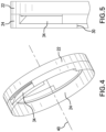
- FIG. 4 is another perspective view of the element backup to bring out features thereof
- FIG. 5 is another perspective view of the element backup to bring out features thereof
- FIG. 6 is a cutaway perspective view of the backup on the tool to illustrate a feature
- FIG. 7 is a perspective view of the element backup of FIG. 3 in phantom to illustrate an interconnection
- FIG. 8 is an enlarged view of the element backup illustrating a release member
- FIG. 9 is a perspective view of an alternate embodiment of an element backup.
- FIGS. 1 A and 1 B an environment for the element backup 10 is illustrated.
- the environment is a borehole tool 12 such as a packer.
- the packer 12 is disposed within a tubular 14 such as a casing or open hole wall.
- the element backups 10 reduce or prevent extrusion of the element 16 .
- the element backups 10 In viewing FIGS. 1 A and 1 B simultaneously, one can see that the element backups 10 must grow radially to achieve their final position as shown in FIG. 1 B . Facilitating this growth without creating extrusion pathways is desirable.
- the element backup 10 is configured as a first ring 22 (or cone ring), that in some embodiments includes a first frustoconical surface 23 , and a second ring 24 (or packer ring), that in some embodiments includes a second frustoconical surface 25 , where the first and second rings are adjacent one another.
- the frustoconical surfaces 23 and 25 come together at a point at a radially inward most extent of the first and second rings
- At least one of the rings includes a parting line 26 (and/or 28 ).
- the illustration of FIG. 3 includes only one parting line 26 for ring 22 and one parting line 28 for ring 24 . It is to be appreciated that more than one parting line is contemplated for each ring and that in some embodiments the plurality of parting lines in a single ring may be evenly distributed around the ring. The number of parting lines contemplated is limited only by practicality of fitting them in a ring. In an embodiment 6 or 8 parting lines is contemplated that may be evenly distributed or not as desired. While not specifically shown, the visage of the parting lines 26 , 28 shown in FIG. 3 will simply be multiplied about the rings.
- Parting lines 26 , 28 include a plurality of segments wherein the plurality is at least a first and a second segment, the segments being disposed at an angle ⁇ to one another as seen in FIG. 3 .
- the angle ⁇ is a nonzero angle meaning that the intersecting segments must intersect one another at something other than zero degrees of angle. In FIG. 3 this is about 90 degrees but more or fewer degrees are contemplated, other than zero.
- the plurality of segments may be three segments as illustrated including generally axial extending segments 30 and 32 and a non-axially extending segment 34 extending between the generally axially extending segments 30 and 32 .
- Segments 34 of each parting line 26 and 28 intersect the first ring surface 23 and second ring surface 25 , respectively, between but not including an inside diameter 35 and an outside diameter 37 of the first ring surface 23 and the second ring surface 25 . It is to be understood that the description above in this paragraph is applicable to a view of the subject ring and parting line from a distance of about a couple of feet to the side of the ring and looking generally radially toward the ring. It is to be appreciated that the parting line segments may each extend through a radial thickness of the rings along radii from an axis 40 defined through the rings 22 and 24 . Alternatively, the segments 30 , 32 and 34 may extend through the radial thickness of the rings 22 and 24 non-radially. In one embodiment, illustrated in FIGS. 4 and 5 , the non-axially extending segment 34 is clearly illustrated to extend through the thickness of the ring 24 at an angle to the axis 40 that is not orthogonal thereto.
- segmented parting line The purpose of the segmented parting line is to allow for portions of the ring to remain annularly complete rather than leaving a large gap, which occurs if the parting line of a ring is a single axial segment. This improves extrusion resistance and can be seen in FIG. 2 . Were it not for the segmented parting line more of the packer ring 24 would be unsupported thereby increasing extrusion risk. As shown in FIG. 6 , the packer ring 24 is supported by a portion of ring 22 giving a greater contact area 42 with a cone 44 . It is also noted in FIG. 6 that in some embodiments there is additionally a protrusion 46 from one or the other of the first and second rings and a complementary recess 48 , in the other of the first and second rings to increase registration of the rings during expansion.
- an interconnection 50 is illustrated connecting the rings 22 and 24 together for both ease of handling during manufacture and swab off resistance during running.
- the interconnection 50 is a mechanical connection between the two rings that is releasable by shearing, or other type of release.
- the interconnection is created in an additive manufacturing operation that produces the element backup 10 in one piece.
- the interconnection 50 will be short sections of material bridging between the first ring 22 and the second ring 24 . These may be in the shape of dashes or plus signs for example or the interconnection may be created merely by changing the density of the material between the two rings so that the material in that location will relatively easily fail under strain. It can be understood from FIG.
- interconnection 50 is disposed orthogonally to the axis 40 of the rings 22 and 24 .
- some embodiments include a release member 52 disposed in the gap represented by segments 30 or 32 . This is another unifying feature that like the foregoing assists in manufacturing, handling and swab off resistance during running.
- FIG. 9 Similar features to the foregoing will carry one hundred series numerals of the numerals used for the above described embodiments while features unique to the embodiment illustrated in FIG. 9 will bear one hundred series numerals larger than those numerals used in connection with the previously described embodiments.
- An element backup 110 is illustrated that creates a greater contact surface area and ring 124 thickness at an extrusion zone (intersection of the element backup 110 and a cone 120 .
- first and second rings 122 , 124 has a modified shape as shown in the Figure to include an apex 160 and an overhang 162 extending from the apex 160 , the apex 160 having a surface 164 extending at an angle from a frustoconical surface 125 .
- the complementary ring 122 is likewise modified such that it will properly nest with the ring 124 .
- the element backup 110 is similar to the foregoing.
- An element backup including a first ring defining an axis; a first parting line through the first ring, the first parting line having a first plurality of generally axially extending segments and a first generally non-axially extending segment extending between the first plurality of axially extending segments; a second ring defining an axis; a second parting line through the second ring, the second parting line having a second plurality of generally axially extending segments and a second generally non-axially extending segment extending between the second plurality of axially extending segments; and an interconnection releasably securing the first and second rings to one another.
- the frustoconical surface includes an apex and an overhang extending from the apex, the apex having a surface extending at an angle from the frustoconical surface.
- both of the first and second rings include frustoconical surfaces.
- the non-orthogonal radial aspect defines a surface that is parallel to a frustoconical surface of one of the first and second rings of which the non-axially extending segment is a part.
- first and second parting lines is a plurality of first and second parting lines disposed about the corresponding first or second ring.
- one of the first and second rings includes a recess and the other of the first and second rings includes a protrusion complementary to the recess.
- a borehole seal configuration including a mandrel; a seal element disposed about the mandrel; an element backup disposed adjacent the seal element, the element backup being defined as in any prior embodiment; a cone disposed adjacent the element backup opposite the seal element.
- a method for making an element backup as in any prior embodiment including depositing a layer of material on a substrate; fusing the layer of material; depositing subsequent layers of material and fusing each layer of material to the next until a completed element backup is formed.
- the teachings of the present disclosure may be used in a variety of well operations. These operations may involve using one or more treatment agents to treat a formation, the fluids resident in a formation, a wellbore, and/or equipment in the wellbore, such as production tubing.
- the treatment agents may be in the form of liquids, gases, solids, semi-solids, and mixtures thereof.
- Illustrative treatment agents include, but are not limited to, fracturing fluids, acids, steam, water, brine, anti-corrosion agents, cement, permeability modifiers, drilling muds, emulsifiers, demulsifiers, tracers, flow improvers etc.
- Illustrative well operations include, but are not limited to, hydraulic fracturing, stimulation, tracer injection, cleaning, acidizing, steam injection, water flooding, cementing, etc.
Abstract
Description
Claims (20)
Priority Applications (7)
| Application Number | Priority Date | Filing Date | Title |
|---|---|---|---|
| US15/991,429 US11713642B2 (en) | 2018-05-29 | 2018-05-29 | Element backup |
| GB2019540.0A GB2589021B (en) | 2018-05-29 | 2019-04-24 | Element backup |
| AU2019279596A AU2019279596B2 (en) | 2018-05-29 | 2019-04-24 | Element backup |
| PCT/US2019/028947 WO2019231586A1 (en) | 2018-05-29 | 2019-04-24 | Element backup |
| CA3101610A CA3101610C (en) | 2018-05-29 | 2019-04-24 | Element backup |
| NO20201354A NO20201354A1 (en) | 2018-05-29 | 2019-04-24 | Element backup |
| US18/321,306 US20230287757A1 (en) | 2018-05-29 | 2023-05-22 | Element Backup |
Applications Claiming Priority (1)
| Application Number | Priority Date | Filing Date | Title |
|---|---|---|---|
| US15/991,429 US11713642B2 (en) | 2018-05-29 | 2018-05-29 | Element backup |
Related Child Applications (1)
| Application Number | Title | Priority Date | Filing Date |
|---|---|---|---|
| US18/321,306 Continuation US20230287757A1 (en) | 2018-05-29 | 2023-05-22 | Element Backup |
Publications (2)
| Publication Number | Publication Date |
|---|---|
| US20190368304A1 US20190368304A1 (en) | 2019-12-05 |
| US11713642B2 true US11713642B2 (en) | 2023-08-01 |
Family
ID=68693084
Family Applications (2)
| Application Number | Title | Priority Date | Filing Date |
|---|---|---|---|
| US15/991,429 Active 2039-08-02 US11713642B2 (en) | 2018-05-29 | 2018-05-29 | Element backup |
| US18/321,306 Pending US20230287757A1 (en) | 2018-05-29 | 2023-05-22 | Element Backup |
Family Applications After (1)
| Application Number | Title | Priority Date | Filing Date |
|---|---|---|---|
| US18/321,306 Pending US20230287757A1 (en) | 2018-05-29 | 2023-05-22 | Element Backup |
Country Status (6)
| Country | Link |
|---|---|
| US (2) | US11713642B2 (en) |
| AU (1) | AU2019279596B2 (en) |
| CA (1) | CA3101610C (en) |
| GB (1) | GB2589021B (en) |
| NO (1) | NO20201354A1 (en) |
| WO (1) | WO2019231586A1 (en) |
Families Citing this family (11)
| Publication number | Priority date | Publication date | Assignee | Title |
|---|---|---|---|---|
| US10704355B2 (en) | 2016-01-06 | 2020-07-07 | Baker Hughes, A Ge Company, Llc | Slotted anti-extrusion ring assembly |
| US10907437B2 (en) | 2019-03-28 | 2021-02-02 | Baker Hughes Oilfield Operations Llc | Multi-layer backup ring |
| US10907438B2 (en) | 2017-09-11 | 2021-02-02 | Baker Hughes, A Ge Company, Llc | Multi-layer backup ring |
| US10689942B2 (en) * | 2017-09-11 | 2020-06-23 | Baker Hughes, A Ge Company, Llc | Multi-layer packer backup ring with closed extrusion gaps |
| US10677014B2 (en) * | 2017-09-11 | 2020-06-09 | Baker Hughes, A Ge Company, Llc | Multi-layer backup ring including interlock members |
| US11142978B2 (en) | 2019-12-12 | 2021-10-12 | Baker Hughes Oilfield Operations Llc | Packer assembly including an interlock feature |
| US11401762B2 (en) * | 2020-03-24 | 2022-08-02 | Ronald van Petegem | Roll-out apparatus, method, and system |
| NO20230237A1 (en) * | 2020-12-04 | 2023-03-03 | Halliburton Energy Services Inc | Radially expandable anti-extrusion backup ring |
| US11725472B2 (en) | 2020-12-23 | 2023-08-15 | Baker Hughes Oilfield Operations Llc | Open tip downhole expansion tool |
| US11525343B2 (en) | 2020-12-23 | 2022-12-13 | Baker Hughes Oilfield Operations Llc | Open tip downhole expansion tool |
| US11492869B2 (en) | 2021-04-05 | 2022-11-08 | Baker Hughes Oilfield Operations Llc | Backup and packer |
Citations (24)
| Publication number | Priority date | Publication date | Assignee | Title |
|---|---|---|---|---|
| US3915424A (en) * | 1973-01-26 | 1975-10-28 | Hydril Co | Blowout preventer with variable inside diameter |
| US5176217A (en) * | 1989-08-31 | 1993-01-05 | Baker Hughes Incorporated | Sealing assembly for subterranean well packing unit |
| US20020043368A1 (en) * | 2000-10-12 | 2002-04-18 | Greene, Tweed Of Delaware, Inc. | Anti-extrusion device for downhole applications |
| US20020070503A1 (en) * | 2000-12-08 | 2002-06-13 | Zimmerman Patrick J. | High temperature and pressure element system |
| US20120025119A1 (en) | 2010-07-30 | 2012-02-02 | Swagelok Company | Anti-Extrusion Packing Support |
| US20120217025A1 (en) * | 2011-02-28 | 2012-08-30 | Smith International, Inc. | Metal expandable element back-up ring for high pressure/high temperature packer |
| US20130147121A1 (en) * | 2011-12-13 | 2013-06-13 | Baker Hughes Incorporated | Backup System for Packer Sealing Element |
| US20130192853A1 (en) * | 2010-10-06 | 2013-08-01 | Packers Plus Energy Services Inc. | Wellbore packer back-up ring assembly, packer and method |
| US20130269929A1 (en) * | 2012-04-16 | 2013-10-17 | Halliburton Energy Services, Inc. | Protected retaining bands |
| US20140190682A1 (en) * | 2013-01-09 | 2014-07-10 | Donald J. Greenlee | Downhole Tool Apparatus with Slip Plate and Wedge |
| US20140262209A1 (en) * | 2013-03-15 | 2014-09-18 | CDI Energy Products | Downhole sealing assembly |
| US20140332239A1 (en) * | 2013-05-07 | 2014-11-13 | Freudenberg Oil & Gas, Llc | Expandable packing element and cartridge |
| US9273526B2 (en) | 2013-01-16 | 2016-03-01 | Baker Hughes Incorporated | Downhole anchoring systems and methods of using same |
| US20160067826A1 (en) * | 2014-09-04 | 2016-03-10 | Baker Hughes Incorporated | Porous structure for downhole fluid control applications and method of manufacture |
| US9784066B1 (en) * | 2015-07-09 | 2017-10-10 | Christopher A. Branton | Downhole bridge plug or packer assemblies |
| US20170350211A1 (en) * | 2016-06-02 | 2017-12-07 | Weatherford Technology Holdings, Llc | Anti-extrusion barrier for packing element |
| US20170370176A1 (en) * | 2014-04-02 | 2017-12-28 | Magnum Oil Tools International, Ltd. | Split ring sealing assemblies |
| US20180023366A1 (en) * | 2016-01-06 | 2018-01-25 | Baker Hughes, A Ge Company, Llc | Slotted Backup Ring Assembly |
| US9995541B2 (en) * | 2011-07-20 | 2018-06-12 | Trumpf Laser Gmbh | Method for forming a composite material, and heat sink |
| US20180283139A1 (en) * | 2014-12-30 | 2018-10-04 | Halliburton Energy Services, Inc | Reusable pre-energized backup ring |
| US20180313184A1 (en) * | 2016-01-11 | 2018-11-01 | Halliburton Energy Services, Inc. | Extrusion limiting ring for wellbore isolation devices |
| US20210332661A1 (en) * | 2020-04-24 | 2021-10-28 | Innovex Downhole Solutions, Inc. | Downhole tool with seal ring and slips assembly |
| US20220081991A1 (en) * | 2020-09-15 | 2022-03-17 | Baker Hughes Holdings Llc | Segmented backup ring, system and method |
| US11473391B2 (en) * | 2017-02-07 | 2022-10-18 | Halliburton Energy Services, Inc. | Packer sealing element with non-swelling layer |
Family Cites Families (3)
| Publication number | Priority date | Publication date | Assignee | Title |
|---|---|---|---|---|
| US9518352B2 (en) * | 2015-01-07 | 2016-12-13 | Haier Us Appliance Solutions, Inc. | Unitary balance ring for a washing machine appliance |
| US10851611B2 (en) * | 2016-04-08 | 2020-12-01 | Baker Hughes, A Ge Company, Llc | Hybrid disintegrable articles |
| US10760369B2 (en) * | 2017-06-14 | 2020-09-01 | Baker Hughes, A Ge Company, Llc | Variable radius backup ring for a downhole system |
-
2018
- 2018-05-29 US US15/991,429 patent/US11713642B2/en active Active
-
2019
- 2019-04-24 WO PCT/US2019/028947 patent/WO2019231586A1/en active Application Filing
- 2019-04-24 NO NO20201354A patent/NO20201354A1/en unknown
- 2019-04-24 AU AU2019279596A patent/AU2019279596B2/en active Active
- 2019-04-24 GB GB2019540.0A patent/GB2589021B/en active Active
- 2019-04-24 CA CA3101610A patent/CA3101610C/en active Active
-
2023
- 2023-05-22 US US18/321,306 patent/US20230287757A1/en active Pending
Patent Citations (24)
| Publication number | Priority date | Publication date | Assignee | Title |
|---|---|---|---|---|
| US3915424A (en) * | 1973-01-26 | 1975-10-28 | Hydril Co | Blowout preventer with variable inside diameter |
| US5176217A (en) * | 1989-08-31 | 1993-01-05 | Baker Hughes Incorporated | Sealing assembly for subterranean well packing unit |
| US20020043368A1 (en) * | 2000-10-12 | 2002-04-18 | Greene, Tweed Of Delaware, Inc. | Anti-extrusion device for downhole applications |
| US20020070503A1 (en) * | 2000-12-08 | 2002-06-13 | Zimmerman Patrick J. | High temperature and pressure element system |
| US20120025119A1 (en) | 2010-07-30 | 2012-02-02 | Swagelok Company | Anti-Extrusion Packing Support |
| US20130192853A1 (en) * | 2010-10-06 | 2013-08-01 | Packers Plus Energy Services Inc. | Wellbore packer back-up ring assembly, packer and method |
| US20120217025A1 (en) * | 2011-02-28 | 2012-08-30 | Smith International, Inc. | Metal expandable element back-up ring for high pressure/high temperature packer |
| US9995541B2 (en) * | 2011-07-20 | 2018-06-12 | Trumpf Laser Gmbh | Method for forming a composite material, and heat sink |
| US20130147121A1 (en) * | 2011-12-13 | 2013-06-13 | Baker Hughes Incorporated | Backup System for Packer Sealing Element |
| US20130269929A1 (en) * | 2012-04-16 | 2013-10-17 | Halliburton Energy Services, Inc. | Protected retaining bands |
| US20140190682A1 (en) * | 2013-01-09 | 2014-07-10 | Donald J. Greenlee | Downhole Tool Apparatus with Slip Plate and Wedge |
| US9273526B2 (en) | 2013-01-16 | 2016-03-01 | Baker Hughes Incorporated | Downhole anchoring systems and methods of using same |
| US20140262209A1 (en) * | 2013-03-15 | 2014-09-18 | CDI Energy Products | Downhole sealing assembly |
| US20140332239A1 (en) * | 2013-05-07 | 2014-11-13 | Freudenberg Oil & Gas, Llc | Expandable packing element and cartridge |
| US20170370176A1 (en) * | 2014-04-02 | 2017-12-28 | Magnum Oil Tools International, Ltd. | Split ring sealing assemblies |
| US20160067826A1 (en) * | 2014-09-04 | 2016-03-10 | Baker Hughes Incorporated | Porous structure for downhole fluid control applications and method of manufacture |
| US20180283139A1 (en) * | 2014-12-30 | 2018-10-04 | Halliburton Energy Services, Inc | Reusable pre-energized backup ring |
| US9784066B1 (en) * | 2015-07-09 | 2017-10-10 | Christopher A. Branton | Downhole bridge plug or packer assemblies |
| US20180023366A1 (en) * | 2016-01-06 | 2018-01-25 | Baker Hughes, A Ge Company, Llc | Slotted Backup Ring Assembly |
| US20180313184A1 (en) * | 2016-01-11 | 2018-11-01 | Halliburton Energy Services, Inc. | Extrusion limiting ring for wellbore isolation devices |
| US20170350211A1 (en) * | 2016-06-02 | 2017-12-07 | Weatherford Technology Holdings, Llc | Anti-extrusion barrier for packing element |
| US11473391B2 (en) * | 2017-02-07 | 2022-10-18 | Halliburton Energy Services, Inc. | Packer sealing element with non-swelling layer |
| US20210332661A1 (en) * | 2020-04-24 | 2021-10-28 | Innovex Downhole Solutions, Inc. | Downhole tool with seal ring and slips assembly |
| US20220081991A1 (en) * | 2020-09-15 | 2022-03-17 | Baker Hughes Holdings Llc | Segmented backup ring, system and method |
Non-Patent Citations (1)
| Title |
|---|
| Notification of Transmittal of the International Search Report and the Written Opinion of the International Searching Authority, or the Declaration; PCT/US2019/028947; dated Sep. 11, 2019; ISR, 3 pages; WO 5 pages, total: 8 pages. |
Also Published As
| Publication number | Publication date |
|---|---|
| GB202019540D0 (en) | 2021-01-27 |
| CA3101610C (en) | 2023-03-28 |
| AU2019279596B2 (en) | 2021-09-30 |
| CA3101610A1 (en) | 2019-12-05 |
| US20230287757A1 (en) | 2023-09-14 |
| GB2589021A (en) | 2021-05-19 |
| NO20201354A1 (en) | 2020-12-10 |
| US20190368304A1 (en) | 2019-12-05 |
| AU2019279596A1 (en) | 2021-01-07 |
| WO2019231586A1 (en) | 2019-12-05 |
| GB2589021B (en) | 2022-10-05 |
Similar Documents
| Publication | Publication Date | Title |
|---|---|---|
| US11713642B2 (en) | Element backup | |
| US10526864B2 (en) | Seal backup, seal system and wellbore system | |
| US10370935B2 (en) | Packer assembly including a support ring | |
| CA2981934C (en) | Packing element back-up system incorporating iris mechanism | |
| CA3102206C (en) | Slip and cone arrangement | |
| US20200173248A1 (en) | Anchoring system for expandable tubulars | |
| US20200095833A1 (en) | Screen assembly and method of forming a screen assembly | |
| US10760371B2 (en) | System for limiting radial expansion of an expandable seal | |
| US11098542B2 (en) | Anchor and method for making | |
| US10927613B2 (en) | Articulating wireline component | |
| US11891875B2 (en) | Expandable annular seal tool and system | |
| US10458210B2 (en) | Manufacturing method of rib support for screen/filter cartridge | |
| US11802464B2 (en) | Segmented expansion cone, method and system | |
| US11053750B2 (en) | Drag block for a downhole tool | |
| US20170191351A1 (en) | Gravel pack joint | |
| US20240125184A1 (en) | Method for attaching ring, ring and system | |
| US20230212923A1 (en) | Resettable backup and system | |
| WO2024086482A1 (en) | Method for attaching ring, ring and system | |
| WO2024039578A1 (en) | Downhole tool connection formed from multiple materials |
Legal Events
| Date | Code | Title | Description |
|---|---|---|---|
| AS | Assignment |
Owner name: BAKER HUGHES, A GE COMPANY, LLC, TEXAS Free format text: ASSIGNMENT OF ASSIGNORS INTEREST;ASSIGNORS:DENG, GUIJUN;XU, YINGQING;KENDALL, ALEXANDER MORRISON;AND OTHERS;SIGNING DATES FROM 20180525 TO 20180529;REEL/FRAME:045924/0805 |
|
| FEPP | Fee payment procedure |
Free format text: ENTITY STATUS SET TO UNDISCOUNTED (ORIGINAL EVENT CODE: BIG.); ENTITY STATUS OF PATENT OWNER: LARGE ENTITY |
|
| STPP | Information on status: patent application and granting procedure in general |
Free format text: NON FINAL ACTION MAILED |
|
| STPP | Information on status: patent application and granting procedure in general |
Free format text: RESPONSE TO NON-FINAL OFFICE ACTION ENTERED AND FORWARDED TO EXAMINER |
|
| STPP | Information on status: patent application and granting procedure in general |
Free format text: DOCKETED NEW CASE - READY FOR EXAMINATION |
|
| STPP | Information on status: patent application and granting procedure in general |
Free format text: NON FINAL ACTION MAILED |
|
| STPP | Information on status: patent application and granting procedure in general |
Free format text: RESPONSE TO NON-FINAL OFFICE ACTION ENTERED AND FORWARDED TO EXAMINER |
|
| STPP | Information on status: patent application and granting procedure in general |
Free format text: FINAL REJECTION MAILED |
|
| STPP | Information on status: patent application and granting procedure in general |
Free format text: ADVISORY ACTION MAILED |
|
| STPP | Information on status: patent application and granting procedure in general |
Free format text: DOCKETED NEW CASE - READY FOR EXAMINATION |
|
| STPP | Information on status: patent application and granting procedure in general |
Free format text: NON FINAL ACTION MAILED |
|
| AS | Assignment |
Owner name: BAKER HUGHES HOLDINGS LLC, TEXAS Free format text: CHANGE OF NAME;ASSIGNOR:BAKER HUGHES, A GE COMPANY, LLC;REEL/FRAME:063361/0869 Effective date: 20200413 |
|
| STPP | Information on status: patent application and granting procedure in general |
Free format text: PUBLICATIONS -- ISSUE FEE PAYMENT VERIFIED |
|
| STCF | Information on status: patent grant |
Free format text: PATENTED CASE |