US11708641B2 - Copper catalysts for electrochemical CO2 reduction to C2+ products - Google Patents
Copper catalysts for electrochemical CO2 reduction to C2+ products Download PDFInfo
- Publication number
- US11708641B2 US11708641B2 US17/393,151 US202117393151A US11708641B2 US 11708641 B2 US11708641 B2 US 11708641B2 US 202117393151 A US202117393151 A US 202117393151A US 11708641 B2 US11708641 B2 US 11708641B2
- Authority
- US
- United States
- Prior art keywords
- foils
- electropolished
- halogenation
- anodic
- agcl
- Prior art date
- Legal status (The legal status is an assumption and is not a legal conclusion. Google has not performed a legal analysis and makes no representation as to the accuracy of the status listed.)
- Active
Links
Images


Classifications
-
- C—CHEMISTRY; METALLURGY
- C25—ELECTROLYTIC OR ELECTROPHORETIC PROCESSES; APPARATUS THEREFOR
- C25F—PROCESSES FOR THE ELECTROLYTIC REMOVAL OF MATERIALS FROM OBJECTS; APPARATUS THEREFOR
- C25F3/00—Electrolytic etching or polishing
- C25F3/16—Polishing
- C25F3/22—Polishing of heavy metals
-
- C—CHEMISTRY; METALLURGY
- C25—ELECTROLYTIC OR ELECTROPHORETIC PROCESSES; APPARATUS THEREFOR
- C25F—PROCESSES FOR THE ELECTROLYTIC REMOVAL OF MATERIALS FROM OBJECTS; APPARATUS THEREFOR
- C25F7/00—Constructional parts, or assemblies thereof, of cells for electrolytic removal of material from objects; Servicing or operating
-
- C—CHEMISTRY; METALLURGY
- C25—ELECTROLYTIC OR ELECTROPHORETIC PROCESSES; APPARATUS THEREFOR
- C25B—ELECTROLYTIC OR ELECTROPHORETIC PROCESSES FOR THE PRODUCTION OF COMPOUNDS OR NON-METALS; APPARATUS THEREFOR
- C25B1/00—Electrolytic production of inorganic compounds or non-metals
- C25B1/01—Products
- C25B1/24—Halogens or compounds thereof
- C25B1/26—Chlorine; Compounds thereof
-
- C—CHEMISTRY; METALLURGY
- C25—ELECTROLYTIC OR ELECTROPHORETIC PROCESSES; APPARATUS THEREFOR
- C25B—ELECTROLYTIC OR ELECTROPHORETIC PROCESSES FOR THE PRODUCTION OF COMPOUNDS OR NON-METALS; APPARATUS THEREFOR
- C25B11/00—Electrodes; Manufacture thereof not otherwise provided for
- C25B11/04—Electrodes; Manufacture thereof not otherwise provided for characterised by the material
- C25B11/051—Electrodes formed of electrocatalysts on a substrate or carrier
- C25B11/052—Electrodes comprising one or more electrocatalytic coatings on a substrate
-
- C—CHEMISTRY; METALLURGY
- C25—ELECTROLYTIC OR ELECTROPHORETIC PROCESSES; APPARATUS THEREFOR
- C25B—ELECTROLYTIC OR ELECTROPHORETIC PROCESSES FOR THE PRODUCTION OF COMPOUNDS OR NON-METALS; APPARATUS THEREFOR
- C25B11/00—Electrodes; Manufacture thereof not otherwise provided for
- C25B11/04—Electrodes; Manufacture thereof not otherwise provided for characterised by the material
- C25B11/051—Electrodes formed of electrocatalysts on a substrate or carrier
- C25B11/055—Electrodes formed of electrocatalysts on a substrate or carrier characterised by the substrate or carrier material
- C25B11/057—Electrodes formed of electrocatalysts on a substrate or carrier characterised by the substrate or carrier material consisting of a single element or compound
- C25B11/061—Metal or alloy
-
- C—CHEMISTRY; METALLURGY
- C25—ELECTROLYTIC OR ELECTROPHORETIC PROCESSES; APPARATUS THEREFOR
- C25B—ELECTROLYTIC OR ELECTROPHORETIC PROCESSES FOR THE PRODUCTION OF COMPOUNDS OR NON-METALS; APPARATUS THEREFOR
- C25B11/00—Electrodes; Manufacture thereof not otherwise provided for
- C25B11/04—Electrodes; Manufacture thereof not otherwise provided for characterised by the material
- C25B11/051—Electrodes formed of electrocatalysts on a substrate or carrier
- C25B11/073—Electrodes formed of electrocatalysts on a substrate or carrier characterised by the electrocatalyst material
- C25B11/075—Electrodes formed of electrocatalysts on a substrate or carrier characterised by the electrocatalyst material consisting of a single catalytic element or catalytic compound
-
- C—CHEMISTRY; METALLURGY
- C25—ELECTROLYTIC OR ELECTROPHORETIC PROCESSES; APPARATUS THEREFOR
- C25B—ELECTROLYTIC OR ELECTROPHORETIC PROCESSES FOR THE PRODUCTION OF COMPOUNDS OR NON-METALS; APPARATUS THEREFOR
- C25B3/00—Electrolytic production of organic compounds
- C25B3/20—Processes
- C25B3/25—Reduction
- C25B3/26—Reduction of carbon dioxide
-
- C—CHEMISTRY; METALLURGY
- C25—ELECTROLYTIC OR ELECTROPHORETIC PROCESSES; APPARATUS THEREFOR
- C25D—PROCESSES FOR THE ELECTROLYTIC OR ELECTROPHORETIC PRODUCTION OF COATINGS; ELECTROFORMING; APPARATUS THEREFOR
- C25D11/00—Electrolytic coating by surface reaction, i.e. forming conversion layers
- C25D11/02—Anodisation
- C25D11/34—Anodisation of metals or alloys not provided for in groups C25D11/04 - C25D11/32
-
- C—CHEMISTRY; METALLURGY
- C25—ELECTROLYTIC OR ELECTROPHORETIC PROCESSES; APPARATUS THEREFOR
- C25D—PROCESSES FOR THE ELECTROLYTIC OR ELECTROPHORETIC PRODUCTION OF COATINGS; ELECTROFORMING; APPARATUS THEREFOR
- C25D21/00—Processes for servicing or operating cells for electrolytic coating
- C25D21/12—Process control or regulation
-
- C—CHEMISTRY; METALLURGY
- C25—ELECTROLYTIC OR ELECTROPHORETIC PROCESSES; APPARATUS THEREFOR
- C25F—PROCESSES FOR THE ELECTROLYTIC REMOVAL OF MATERIALS FROM OBJECTS; APPARATUS THEREFOR
- C25F3/00—Electrolytic etching or polishing
- C25F3/16—Polishing
- C25F3/22—Polishing of heavy metals
- C25F3/26—Polishing of heavy metals of refractory metals
Definitions
- the present invention relates generally to catalysts for the selective electroreduction of carbon dioxide (CO 2 ) to high-value products, and specifically to copper catalysts for electrochemical CO 2 reduction to C 2+ products.
- CO 2 carbon dioxide
- CO 2 carbon dioxide
- CO 2 RR electrochemical CO 2 reduction reaction
- the invention features an electrochemical method including performing anodic halogenation of Cu foils, performing subsequent oxide-formation in a KHCO 3 electrolyte, and performing an electroreduction in neutral KHCO 3 to generate a copper catalyst.
- the invention features method of preparing electrocatalysts including mechanically polishing Cu foils, rinsing the polished Cu foils, electropolishing the Cu foils by chronoamperometry in 85% phosphoric acid at 1.5 V with a Cu counter electrode in a two-electrode configuration, rinsing the electropolished Cu foils, cutting the electropolished Cu foils into 2 ⁇ 0.5 cm 2 pieces, flattening the electropolished Cu foils, covering a back side and part of a front side of the flattened electropolished Cu foils with polyimide (PI) tape to define a geometric area of a working electrode, and wrapping the working electrode in PTFE tape to prevent detachment of the PI tape, exposing an area of 0.35 cm 2 .
- PI polyimide
- FIG. 1 illustrates an exemplary scheme
- FIG. 2 illustrates an anodic halogenation of Cu foils.
- FIGS. 3 A- 3 E illustrate crystal structures of halogenated Cu identified by GI-XRD.
- FIG. 4 A- 4 L illustrate a morphology of halogenated Cu foil electrodes.
- FIG. 5 illustrates cross-sectional SEM images.
- FIG. 6 illustrates plan-view SEM images.
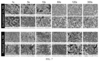
- FIG. 7 illustrates plan-view SEM images.
- FIG. 8 illustrates plan-view SEM images.
- FIG. 9 illustrates plan-view SEM images.
- FIG. 10 illustrates plan-view SEM images.
- FIG. 11 A- 11 D illustrate GI-XRD data.
- FIG. 12 A- 12 C illustrate linear sweep voltammetry (LSV) data.
- FIG. 13 illustrates GI-XRD data
- FIG. 14 A- 14 H illustrate energy-dispersive X-ray spectroscopy (EDS).
- FIG. 15 A- 15 H illustrate performance of catalysts for electrochemical CO 2 RR.
- FIG. 16 A- 16 F illustrates an effect of halogenation time on the performance of the catalysts for CO 2 RR.
- FIG. 17 A- 17 B illustrates linear scale and log-scale plots.
- FIG. 18 illustrates a table of representative FEs.
- FIG. 19 illustrates a flow diagram
- FIG. 20 A- 20 B illustrate double-layer (DL) capacitance measurements.
- FIG. 21 A- 21 C illustrate a relation between surface roughness of the electrocatalysts and HER.
- FIG. 22 A- 22 D illustrate calculated concentration of ions in CO 2 -saturated 0.1 M KHCO 3 as a function of pH.
- FIG. 23 A- 23 C illustrate GI-XRD data.
- FIG. 24 A- 24 F illustrates an exemplary scheme.
- the present invention is a scalable method for preparing Cu electrocatalysts that favor CO 2 conversion to C 2+ products. This method involves anodic halogenation of Cu foils and their subsequent surface reconstruction by oxide-formation and electrochemical reduction. This method results in catalysts that convert CO 2 to ethylene with faradaic efficiencies (FE) up to 50.0% and with FE for total C 2+ products of 72% at ⁇ 1.09 V vs. reversible hydrogen electrode (RHE).
- FE faradaic efficiencies
- the first step of electrochemical CO 2 RR must be enhanced.
- This first step involves a one electron, one proton reduction of CO 2 to form adsorbed COOH (*COOH) and is a reaction that is affected by the concentration ratio of dissolved CO 2 to protons ([CO 2 ]/[H+]) near the electrode surface.
- the relative concentration of dissolved CO 2 and protons near the electrode surface under conditions used for the electrochemical CO 2 RR is significantly different from bulk concentrations.
- the high current densities observed at highly roughened electrocatalysts causes the pH to increase rapidly to as high as 11.
- the efficiency of CO 2 RR is reduced due to limited mass transport of CO 2 on the highly rough surface. Therefore, to favor electrochemical CO 2 RR over HER, a catalyst with minimal roughness should be used to mitigate the rise of local pH.
- the thickness of the interfacial diffusion layer near the catalyst surface also should be reduced.
- catalysts should be designed to take advantage of new insights gained from simulations of the electrochemical CO 2 RR. These simulations have provided an energy landscape that relates the energetics of competing reaction pathways available on Cu. For example, the onset potential to form adsorbed CO (*CO) is predicted to be lowest on the (211) step site of Cu among the three crystal facets of Cu simulated: (111), (100), and (211). Adsorbed CO is an important intermediate in the pathway that leads to C 2 products by C—C coupling. Once *CO is formed on a Cu surface, the activation energy barrier to form the C—C coupling product, *OCCO, is thermodynamically lowest on Cu (100) relative to (111) and (211).
- the energy barrier for CO dimerization decreases with increased *CO coverage.
- C 2 product formation follows second-order kinetics with a rate that is proportional to the concentration of reactive C 1 intermediates such as *CO.
- the rate determining step is dimerization of CO to form C 2 products.
- Other C 1 intermediates possessing unsaturated bonds (*CHO, *COH, *CH2, and *CHOH), which are derived by reduction of *CO, react with *CO to yield C 2+ products.
- a high surface coverage of reactive C 1 intermediates are needed, which can be obtained by a high density of active sites (i.e., surface defects).
- Defect sites such as grain boundaries, step sites, and vacancies that result in under-coordinated atoms on the surface of a catalyst promote C—C coupling.
- Cu + and subsurface oxygen in Cu may promote the adsorption of CO 2 and the C—C coupling, although the stability of subsurface oxygen remains controversial.
- At least six different chemical reactions occur when cycling Cu foils between oxidizing and reducing potentials: (1) dissolution (i.e., corrosion) of Cu + or Cu 2+ cations into the electrolyte at an oxidizing potential, (2) formation of CuCl in the presence of KCl at an oxidizing potential, (3) conversion of CuCl into Cu 2 O, (4) electrodeposition of dissolved Cu + or Cu 2 cations onto the Cu electrode at a reducing potential, and (5-6) reduction of Cu 2 O and CuCl to Cu at a reducing potential. Any one of these reactions can affect the performance of the catalyst.
- the present invention is an advance over previous methods because, as one example, it involves three steps that have the characteristics desirable for carbon utilization technologies: simple to perform, consistent, regenerative, and scalable. As shown in FIG. 1 , these steps are (i) anodic halogenation of Cu foils, (ii) subsequent oxide-formation in a KHCO 3 electrolyte, and (iii) electroreduction.
- chlorinated Cu, brominated Cu, or iodinated Cu were prepared by applying an oxidative potential to Cu foils immersed in 0.1 M KCl, KBr, or KI, respectively, and are henceforth denoted as Cu_KCl, Cu_Br, and Cu_KI to reflect the different electrolytes used for anodic halogenation.
- EDS also provides evidence that subsurface oxygen at the defect sites of Cu_KCl, Cu_Br, and Cu_KI are produced during CO 2 RR via oxidation of Cu by high local pH of the electrolyte.
- the efficiency of these catalysts at converting CO 2 to C 2 and C 3 products by electrochemical CO 2 RR provides strong evidence that both a high density of defect sites and low roughness are critical to promoting the formation of C 2+ products through electrochemical CO 2 RR by minimizing competing HER and C 1 production.
- Halogenated Cu foils were prepared by applying an oxidative potential to electropolished Cu foils immersed in an electrolyte containing halide ions.
- a three-electrode configuration was used: Cu foil working electrode, Pt gauze counter electrode, and Ag/AgCl reference electrode.
- the open circuit potential (OCP) of Cu foil immersed in 0.1 M KCl, KBr, or KI aqueous electrolyte was ⁇ 0.115 V, ⁇ 0.134 V, and ⁇ 0.315 V vs. Ag/AgCl, respectively (see FIG. 2 ).
- Chronoamperometric potentials of 1.1 V, 0.18 V, and ⁇ 0.2 V vs.
- V eff V app ⁇ V oc
- V app the applied potential
- V oc the measured OCP.
- an applied potential of ⁇ 0.2 V vs. Ag/AgCl in 0.1 M KI corresponds to an effective potential of 0.115 V vs. Ag/AgCl, which anodically iodinates the Cu.
- Current density vs. anodic halogenation time for each electrolyte is shown in FIG. 2 .
- GI-XRD Grazing Incident X-ray Diffraction
- FIGS. 3 A- 3 E the crystal structure of Cu foils subjected to anodic halogenation was identified by Grazing Incident X-ray Diffraction (GI-XRD). Included is GI-XRD data of control samples: the original electropolished Cu foil ( FIG. 3 A ) and of electropolished Cu foil after being oxidized in the absence of halide ions (0.05 M K 2 SO 4 aqueous electrolyte, 1.1 V vs. Ag/AgCl, 300 s) ( FIG. 3 B ).
- the GI-XRD data of the control sample shows that oxidation in the absence of halide ions produces Cu 2 O on the surface of the Cu foil.
- anodic halogenation of electropolished Cu foils in KCl, KBr, or KI results in the formation of CuCl, CuBr, or CuI, respectively ( FIGS. 3 C- 3 E ).
- FIG. 4 A- 4 L The morphology of the Cu foils was expected to change with changes in crystal structure. Therefore, SEM was used to examine samples subjected to anodic halogenation for 50 s ( FIG. 4 A- 4 L ). SEM images of samples halogenated for other lengths of time and at different applied potentials are shown in FIGS. 14 A- 14 H , FIGS. 15 A-H , FIGS. 16 A- 16 F and FIGS. 21 A- 21 C and SEM images of the control sample are shown in FIG. 10 .
- FIGS. 4 A- 4 C Plan-view SEM images of the as-prepared Cu(I) halide are shown in FIGS. 4 D- 4 F .
- the formation of a surface layer of Cu(I) halide during anodic halogenation causes a volume expansion that results in surface wrinkling to relieve mechanical stress. This wrinkling is observed in Cu_KCl and Cu_KBr samples but not in the Cu_KI sample, where instead, triangle-based pyramids emerge.
- the catalysts were subjected to two additional treatments to determine if the morphology of the surface changes further when halogenated Cu foils are immersed in an electrolyte commonly used for CO 2 RR experiments: (1) immersion in air-saturated KHCO 3 , where the pH is basic and (2) electrochemical reduction in CO 2 -saturated KHCO 3 , where the pH is nearly neutral (pH 6.8).
- immersion in air-saturated KHCO 3 where the pH is basic
- electrochemical reduction in CO 2 -saturated KHCO 3 where the pH is nearly neutral (pH 6.8).
- An air-saturated solution of 0.1 M KHCO 3 has a measured pH of 9.0, whose basicity is derived from a shift in equilibrium from bicarbonate ion to its weak acid (H2CO 3 ) to produce OH ⁇ ions: HCO 3 ⁇ (aq)+H 2 O(aq) ⁇ H 2 CO 3 (aq)+OH ⁇ (aq) (1)
- morphological changes should reflect the coordination affinity of copper(I) halides (CuCl ⁇ CuBr ⁇ CuI) and their solubility product (K SP) in aqueous solution (CuCl>CuBr>CuI).
- Cu_KI does not undergo significant oxide-formation in the prior experiment (i.e., immersion in air-saturated KH CO 3 electrolyte).
- the electrochemical reduction of Cu_KI causes an abrupt release of iodide ions, leading to the dramatic change in morphology that is observed.
- bromide ions from Cu_KBr are released gradually by the oxide-forming reaction before the sample is subjected to electrochemical reduction.
- Cu_KCl undergoes relatively rapid oxide-formation in KH CO 3 electrolyte so that its morphology has already changed prior to being subjected to electrochemical reduction.
- the elemental compositions (Cu, O, and halogen atoms) of the surface of Cu_KX were determined using EDS for the purpose of relating changes in chemical composition to changes in morphology.
- Raw EDS data are shown in FIGS. 14 A- 14 D , which can be converted into compositions of molecular species ( FIGS. 14 E- 14 H ) using the chemical species identified by GI-XRD experiments.
- the halogenated catalysts consist of only three chemical species (i.e., Cu, Cu 2 O, and CuX) because other species such as CuO were not observed in the GI-XRD data (see FIGS. 11 A- 11 D and 13 ).
- electropolished Cu only two chemical species are assumed to exist: Cu and Cu 2 O.
- the initial surface species of Cu_KCl and Cu_KBr are converted into Cu 2 O by the oxide-forming reaction [eq. (3)] when the samples are immersed in air-saturated 0.1 M KHCO 3 for 10 min ( FIGS. 14 F and 14 G ).
- EDS data indicates the as-prepared Cu_KCl contains 4.06% of Cu 2 O and 67.3% of CuCl.
- as-prepared Cu_KBr contains 4.13% of Cu 2 O and 66.6% of CuBr.
- rapid oxide-formation occurs: Cu_KCl contains 46.2% of Cu 2 O and 12.0% of CuCl while Cu_KBr contains 63.7% of Cu 2 O and 22.4% of CuBr.
- Cu_KI showed only slight changes to the composition of the initial surface species due to the high stability of CuI in basic KH CO.
- the as-prepared sample contained 16.1% of Cu 2 O and 83.9% of CuI whereas the immersed sample contained 21.6% of Cu 2 O and 78.3% of CuI ( FIG. 14 H ).
- Electrochemical reduction of Cu_KX samples by LSV is expected to reduce all Cu(I) species to Cu 0.
- the converted EDS data reveal ( FIGS. 14 G and 14 H ), however, that 0.33% of CuBr and 0.12% of CuI remains on the surface of the respective catalysts with the Cu_KI sample having a relatively higher content of Cu 2 O (22.7%) than either the Cu_KCl or Cu_KBr samples ( ⁇ 10%).
- the high content of Cu 2 O in the Cu_KI is likely due to re-oxidation of the surface upon exposure to air during the time between sample preparation and EDS measurement ( ⁇ 30 min) and indicates that reduced Cu_KI is particularly susceptible to re-oxidation by air.
- the chemical composition of electropolished Cu does not change significantly when immersed in air-saturated KHCO 3 for 10 min and subsequently electrochemically reduced by LSV as shown in the converted EDS data ( FIG. 14 E ).
- the percentage of Cu 2 O at electropolished Cu does increase slightly from 1.7% to 2.9% upon immersion in air-saturated KHCO 3 for 10 min. This slight increase in Cu 2 O occurs via the oxidation reaction predicted by the Pourbaix diagram for copper: Cu(s)+OH ⁇ (aq) ⁇ Cu 2 O(s)+2 e ⁇ (aq)+H + (aq) (5)
- this reaction is likely to be a weak but important driving force that enables electrocatalysts to maintain C+ and subsurface oxygen despite the highly negative potentials used for electrochemical CO 2 RR.
- the oxidation reaction [Eq. (5)] will generate C + and subsurface oxygen at those defect sites where the local pH is high during the electrochemical CO 2 RR.
- the catalysts were prepared via halogenation of a Cu foil for different lengths of time (i.e., 100 s for Cu_KCl, 60 s for Cu_KBr, and 1 s for Cu_KI) to ensure complete coverage of the Cu substrate with Cu(I) halide.
- the major product obtained on Cu(I)-halide-derived catalysts was C 2 H 4 , with its highest FE (45.1% on Cu_KCl, 49.5% on Cu_Kbr, and 44.5% on Cu_KI) observed at ⁇ 2.1 V vs. Ag/AgCl (see FIG. 18 ).
- the major product obtained on electropolished Cu was CH 4 , with its highest FE (54.0%) at the same potential.
- the Cu(I)-halide-derived catalysts produced CO with FEs in the range of 23-28% at potentials as low as ⁇ 1.3 V vs. Ag/AgCl whereas electropolished Cu at this potential yielded CO with a FE of only 0.5%.
- Adsorbed CO (*CO) is an important intermediate required for production of C 2 and C 3 products via C—C bond coupling.
- the rate of reaction to produce C 2 H 4 is second order with respect to the surface concentration of adsorbed CO (*CO).
- a high density of active sites on the surface of the catalyst is necessary to produce a high surface concentration of *CO.
- FIGS. 16 A- 16 F The effect of anodic halogenation time on CO 2 RR performance also was investigated ( FIGS. 16 A- 16 F ). All data shown in FIGS. 16 A- 16 F were collected at ⁇ 2.1 V vs. Ag/AgCl, where the FE for H 2 was the lowest amongst all applied potentials studied.
- FIGS. 6 - 8 reveal that the underlying electropolished Cu substrate is exposed when anodic halogenation is performed for short periods of time.
- the Cu_KX catalysts produced by anodic halogenation for a short reaction time showed relatively high amounts of CH 4 and low amounts of C 2 H 4 and H 2 , a product distribution expected from electropolished Cu.
- anodic halogenation needs to be applied for at least 60 s for Cu_KCl, 60 s for Cu_KBr and 5 s for Cu_KI.
- 3.82 C/cm 2, 0.80 C/cm 2, and 0.028 C/cm 2 of charge per unit area of electrode was used to make CuCl, CuBr, and CuI layers on electropolished Cu, respectively.
- the amount of charge vs. different amounts of time used for anodic halogenation is shown in FIGS. 17 A- 17 B .
- n hal (charge to produce Cu(I) halide)/(total charge flowed) (6)
- FE for H 2 on all three Cu(I)-halide-derived catalysts increases significantly (i.e., FE for H 2 was 17.4% on Cu_KCl, 15.1% on Cu_KBr, and 19.9% on Cu_KI).
- an optimal halogenation time was sought for each Cu_KX catalyst.
- the Cu_KCl catalyst that generated C 2 H 4 with a FE of 50.2% and C 2+ products with a FE of 70.7% was prepared using an anodic chlorination time of 60 s.
- the Cu_Kbr catalyst that generated C 2 H 4 with a FE of 50.9% and C 2+ products with a FE of 71.5% was prepared using an anodic bromination time of 90 s and the Cu_KI catalyst that generated C 2 H 4 with a 50.0% and C 2+ products with a FE of 72.6% was prepared using an anodic iodination time of only 10 s (see FIG. 18 ).
- Anodic halogenation generates a high density of active sites, which can be crystal grain boundaries or defect sites such as step atoms or under-coordinated atoms. These active sites in turn increase the production of C 2 products from CO 2 RR. If halogenation time is too long, however, the competing HER increases because the surface of the catalyst becomes too rough (see FIG. 19 ).
- the roughness factor of an electrocatalyst can be determined by the double-layer (DL) capacitance method with the assumption that the surface charge is constant across different kinds of catalysts (see FIG. 20 A- 20 B ).
- FIG. 21 A shows the relative roughness of Cu_KX as measured by DL capacitance, which are related as:
- FIG. 21 A shows the relationship between the roughness of the catalysts, FE for H 2 , and halogenation time. This correlation between roughness and HER can be explained by a decrease in the concentration ratio of dissolved CO 2 to proton ([CO 2 ]/[H+]) near the surface of the catalyst at high local pH. Although the buffering capacity of the bicarbonate electrolyte minimizes any increase in pH, the high current density observed at catalysts with high roughness rapidly depletes protons in the interfacial region and leads to a high local pH.
- Simulations of the electrochemical CO 2 RR indicate the local pH is 10.75 when conditions are specified to have a concentration of 0.1 M KHCO 3 , an interfacial diffusion layer thickness of 0.1 mm, and a current density of 15 mA/cm 22. These simulations also show that the local pH can be reduced to 9.6 when the interfacial diffusion layer thickness is reduced by an order of magnitude to 0.01 mm.
- stirring the electrolyte reduces the interfacial diffusion layer thickness, thereby mitigating a rise in local pH and HER.
- stirring facilitates mass transport of chemical reactants from bulk solution to the surface of the electrode.
- the FEs for H 2 , C 2 H 4 , and C 2+ products were 9.3%, 50.0% and 72.6%, respectively, using Cu foils iodinated for 10 s (see FIG. 5 ).
- Anodic halogenation of electropolished Cu followed by surface reconstruction from base-induced oxide formation and electroreduction creates a surface with a high density of defect sites. These sites stabilize species such as Cu + and subsurface oxygen, which are known to promote C 2+ production during the electrochemical CO 2 RR.
- Evidence of a high density of defect sites on the surface of Cu_KX catalysts is provided by incidence-angle dependent GI-XRD data ( FIG. 23 A- 23 C ), which shows decreased crystal ordering at the surface of Cu_KBr during surface reconstruction.
- EDS data reveals the high susceptibility of these surfaces to re-oxidation.
- the density of defect sites in oxide-derived Cu has recently been determined using positron annihilation spectroscopy (PAS). Based on our results, we conclude that a high density of defect sites is the most important attribute of a Cu catalyst that selectively converts CO 2 into C 2+ products via the electrochemical CO 2 RR.
- PAS positron annihilation spectroscopy
- C 2 H 6 ethane
- Cu(I)-halide-derived catalysts were prepared using anodic halogenation.
- the optimal time and voltage for anodic halogenation was 60-100 s at 1.1 V, 60-90 s at 0.18 V, and 10 s at ⁇ 0.2 V vs.
- Iodide ions react with the Cu surface rapidly at weak oxidative potentials because of the high affinity of I—to form CuI.
- All Cu foils were mechanically polished with 400 grit sandpaper, and rinsed with deionized (DI) water.
- the Cu foils (2 ⁇ 5 cm 2 ) subsequently were electropolished by chronoamperometry in 85% phosphoric acid at 1.5 V with a Cu counter electrode in a two-electrode configuration.
- the electropolished Cu foils were rinsed with DI water.
- the foils were flattened and both the back side and part of the front side were covered with polyimide (PI) tape to define the geometric area of the working electrode.
- the electrode was wrapped in PTFE tape to prevent detachment of the PI tape.
- the exposed geometric area was typically 0.35 cm 2 KCl (Macron fine chemicals), KBr (Fisher Scientific), and KI (Fisher Scientific) were dissolved in DI water to a concentration of 0.1 M.
- Anodic chlorination, bromination, and iodination was performed on an electropolished Cu foil immersed in 0.1 M KCl, Kbr, and KI at 1.1 V, 0.18 V, and ⁇ 0.2 V vs. Ag/AgCl, respectively, in a three-electrode configuration using a potentiostat (Pine Instrument Company, Biopotentiostat, model AFCBP1).
- the counter electrode was Pt gauze and the reference electrode was Ag/AgCl (saturated KCl) electrode.
- the open circuit potentials of electropolished Cu in 0.1 M KCl, KBr, and KI was ⁇ 0.115 V, ⁇ 0.134 V, and ⁇ 0.315 V vs. Ag/AgCl, respectively ( FIG. 24 A- 24 F ).
- SEM images were acquired using a LEO 1530 VP ultra-high resolution field emitter SEM at 10 kV. Elemental analysis of samples was obtained using the EDS accessory (Oxford Instruments, Inca X-sight, model 7426) of the SEM.
- the GI-XRD data were obtained using a Bruker D8 Discovery High resolution X-ray Diffractometer at incidence angle of 2° and wavelength of 1.54 ⁇ .
- the double-layer capacitance was measured by cyclic voltammetry in the potential range from ⁇ 0.35 to ⁇ 0.5 V vs. Ag/AgCl in CO 2 -saturated 0.1 M KH CO 3 after electrochemical CO 2 RR.
- Electrochemical CO 2 RR was carried out in a custom made two compartment cell, separated by a Nafion 117 proton-exchange membrane.
- the two compartments were filled with 8.2 ml of 0.1 M KH CO 3 (Sigma-Aldrich, ⁇ 99.95%) electrolyte.
- a three-electrode configuration was employed: Cu foil working electrode, Pt gauze counter electrode, and a home-built Ag/AgCl reference electrode. The working and reference electrodes were placed in the cathode compartment and the Pt gauze counter electrode was placed in the anode compartment.
- the halogenated Cu foil electrode Prior to initiating electrochemical CO 2 RR, the halogenated Cu foil electrode was immersed in 0.1 M KH CO 3 electrolyte and linear sweep voltammetry was performed with a scan rate of 5 mV/s from the open circuit potential to the working potential (usually ⁇ 0.2 V to ⁇ 2.1 V vs Ag/AgCl). Subsequently, CO 2 RR was performed with fresh electrolyte saturated with CO 2 . Before and during electrochemical CO 2 RR, the cell was purged continuously with CO 2 at a flow rate of 20 mL/min as measured with a rotameter (OMEGA FL-3841G FT-032-41-GL-VN).
- Electrochemical CO 2 RR was performed by chronoamperometry for 40 min with a magnetic stirring bar spinning at 1500 rpm.
- a Thermolyne Nuova stir plate (model No. SP18425) was used to stir a 1-cm-long magnetic bar in the electrolyte.
- the stirring speed was calibrated in comparison with the Fisher Scientific hot plate/stirrer (Cat. No. 11-100-49SH). It is worth noting that all experimental results on electrochemical CO 2 RR were obtained while stirring the electrolyte with a magnetic stirrer at 1500 rpm.
- the reduction compartment of the gas-tight reactor was connected to the inlet of the sample loop of a gas chromatograph (GC, Buck Scientific, Model 910). GC measurements were performed on sample injections taken after 10 min and 38 min of the CO 2 RR to determine the concentration of gaseous products present: CO, CH 4 , C 2 H 4 , H 2 .
- the GC was equipped with a methanizer and a flame ionization detector (FID) to detect CO and hydrocarbons and a thermal conductivity detector (TCD) to detect H 2 . Nitrogen was used as the carrier gas. Liquid products were quantified using 1D 1H NMR (400 MHz, Bruker high field NMR spectrometers).
Landscapes
- Chemical & Material Sciences (AREA)
- Organic Chemistry (AREA)
- Engineering & Computer Science (AREA)
- Chemical Kinetics & Catalysis (AREA)
- Electrochemistry (AREA)
- Materials Engineering (AREA)
- Metallurgy (AREA)
- Inorganic Chemistry (AREA)
- Automation & Control Theory (AREA)
- Catalysts (AREA)
Abstract
Description
HCO3 −(aq)+H2O(aq)↔H2CO3(aq)+OH−(aq) (1)
CO2+H2O(aq)↔H2CO3(aq)↔H+(aq)+HCO3 −(aq)↔2H+(aq)+CO3 2−(aq) (2)
2CuX(s)+OH−(aq)↔Cu2O(s)+2X−(aq)+H+(aq) (3)
CuI(s)+e −→Cu(s)+I−(aq) (4)
Cu(s)+OH−(aq)↔Cu2O(s)+2e−(aq)+H+(aq) (5)
n hal=(charge to produce Cu(I) halide)/(total charge flowed) (6)
Cu(s)↔Cu2+ or Cu+(aq)+2e − or e − (7)
V comp (Ag/AgCl)=V appl (Ag/AgCl)+iR
V comp (RHE)=V comp (Ag/AgCl)+0.197+0.059*pH
Claims (8)
Priority Applications (1)
| Application Number | Priority Date | Filing Date | Title |
|---|---|---|---|
| US17/393,151 US11708641B2 (en) | 2020-08-03 | 2021-08-03 | Copper catalysts for electrochemical CO2 reduction to C2+ products |
Applications Claiming Priority (2)
| Application Number | Priority Date | Filing Date | Title |
|---|---|---|---|
| US202063060213P | 2020-08-03 | 2020-08-03 | |
| US17/393,151 US11708641B2 (en) | 2020-08-03 | 2021-08-03 | Copper catalysts for electrochemical CO2 reduction to C2+ products |
Publications (2)
| Publication Number | Publication Date |
|---|---|
| US20220042198A1 US20220042198A1 (en) | 2022-02-10 |
| US11708641B2 true US11708641B2 (en) | 2023-07-25 |
Family
ID=80113653
Family Applications (1)
| Application Number | Title | Priority Date | Filing Date |
|---|---|---|---|
| US17/393,151 Active US11708641B2 (en) | 2020-08-03 | 2021-08-03 | Copper catalysts for electrochemical CO2 reduction to C2+ products |
Country Status (1)
| Country | Link |
|---|---|
| US (1) | US11708641B2 (en) |
Families Citing this family (3)
| Publication number | Priority date | Publication date | Assignee | Title |
|---|---|---|---|---|
| CN114836781B (en) * | 2022-02-28 | 2023-10-03 | 郑州大学 | Preparation method and application of lamellar Cu-based N-doped graphene catalyst |
| CN114622236B (en) * | 2022-03-22 | 2023-05-16 | 北京航空航天大学 | Oxide-derived densely arranged copper array material and preparation method and application thereof |
| US11905607B2 (en) * | 2022-06-09 | 2024-02-20 | The Hong Kong Polytechnic University | Pure-H2O-fed electrocatalytic CO2 reduction to C2H4 beyond 1000-hour stability |
-
2021
- 2021-08-03 US US17/393,151 patent/US11708641B2/en active Active
Non-Patent Citations (59)
Also Published As
| Publication number | Publication date |
|---|---|
| US20220042198A1 (en) | 2022-02-10 |
Similar Documents
| Publication | Publication Date | Title |
|---|---|---|
| US11708641B2 (en) | Copper catalysts for electrochemical CO2 reduction to C2+ products | |
| Kim et al. | Time-resolved observation of C–C coupling intermediates on Cu electrodes for selective electrochemical CO 2 reduction | |
| Yang et al. | Electrocatalysis in alkaline media and alkaline membrane-based energy technologies | |
| Jiang et al. | Enhanced electrochemical CO2 reduction to ethylene over CuO by synergistically tuning oxygen vacancies and metal doping | |
| Page et al. | A study of methanol electro-oxidation reactions in carbon membrane electrodes and structural properties of Pt alloy electro-catalysts by EXAFS | |
| Arai et al. | AC impedance analysis of bifunctional air electrodes for metal‐air batteries | |
| Suzuki et al. | Influence of CO2 dissolution into anion exchange membrane on fuel cell performance | |
| Van Cleve et al. | Tailoring electrode microstructure via ink content to enable improved rated power performance for platinum cobalt/high surface area carbon based polymer electrolyte fuel cells | |
| US11268199B2 (en) | Core/shell-vacancy engineering (CSVE) of catalysts for electrochemical CO2 reduction | |
| Ovalle et al. | Impact of electrolyte anions on the adsorption of CO on Cu electrodes | |
| EP2958173A1 (en) | Catalyst for solid polymer fuel cells and method for producing same | |
| Yang et al. | A rigorous electrochemical ammonia electrolysis protocol with in operando quantitative analysis | |
| Guo et al. | Transient Solid‐State Laser Activation of Indium for High‐Performance Reduction of CO2 to Formate | |
| US11390959B2 (en) | Boron-doped copper catalysts for efficient conversion of CO2 to multi-carbon hydrocarbons and associated methods | |
| Briega-Martos et al. | Hydrogen peroxide and oxygen reduction studies on Pt stepped surfaces: surface charge effects and mechanistic consequences | |
| Jiang et al. | Local coordination and reactivity of a Pt single-atom catalyst as probed by spectroelectrochemical and computational approaches | |
| Abdo et al. | Nafion/Polyaniline composite membranes for hydrogen production in the Cu–Cl thermochemical cycle | |
| Liu et al. | Preparation of a thin-film Pt electrocatalyst by MnO2 electrodeposition and galvanic replacement reaction for oxidation of methanol | |
| Pérez-Rodríguez et al. | Insights on the electrochemical oxidation of ordered mesoporous carbons | |
| Buggy et al. | Evaluating the effect of ionomer chemical composition in silver-ionomer catalyst inks toward the oxygen evolution reaction by half-cell measurements and water electrolysis | |
| Diercks et al. | Spectroscopy vs. electrochemistry: catalyst layer thickness effects on operando/in situ measurements | |
| Anjana et al. | Effect of local pH change on non-PGM catalysts–a potential-dependent mechanistic analysis of the oxygen reduction reaction | |
| Gustavsen et al. | Sodium Persulfate Pre‐treatment of Copper Foils Enabling Homogenous Growth of Cu (OH) 2 Nanoneedle Films for Electrochemical CO2 Reduction | |
| Fukunaga et al. | Direct preparation of core-shell platinum cathode in membrane electrode assembly catalyst layer for polymer electrolyte fuel cell | |
| Liu et al. | Improved catalytic performance of CO2 electrochemical reduction reaction towards ethanol on chlorine-modified Cu-based electrocatalyst |
Legal Events
| Date | Code | Title | Description |
|---|---|---|---|
| FEPP | Fee payment procedure |
Free format text: ENTITY STATUS SET TO UNDISCOUNTED (ORIGINAL EVENT CODE: BIG.); ENTITY STATUS OF PATENT OWNER: SMALL ENTITY |
|
| FEPP | Fee payment procedure |
Free format text: ENTITY STATUS SET TO SMALL (ORIGINAL EVENT CODE: SMAL); ENTITY STATUS OF PATENT OWNER: SMALL ENTITY |
|
| STPP | Information on status: patent application and granting procedure in general |
Free format text: NON FINAL ACTION MAILED |
|
| STPP | Information on status: patent application and granting procedure in general |
Free format text: RESPONSE TO NON-FINAL OFFICE ACTION ENTERED AND FORWARDED TO EXAMINER |
|
| STPP | Information on status: patent application and granting procedure in general |
Free format text: NON FINAL ACTION MAILED |
|
| AS | Assignment |
Owner name: BROWN UNIVERSITY, RHODE ISLAND Free format text: ASSIGNMENT OF ASSIGNORS INTEREST;ASSIGNOR:PALMORE, G. TAYHAS R.;REEL/FRAME:063663/0924 Effective date: 20210729 |
|
| AS | Assignment |
Owner name: BROWN UNIVERSITY, RHODE ISLAND Free format text: ASSIGNMENT OF ASSIGNORS INTEREST;ASSIGNOR:KIM, TAEHEE;REEL/FRAME:063835/0438 Effective date: 20230602 |
|
| STPP | Information on status: patent application and granting procedure in general |
Free format text: PUBLICATIONS -- ISSUE FEE PAYMENT VERIFIED |
|
| STCF | Information on status: patent grant |
Free format text: PATENTED CASE |