US11708128B2 - Systems and methods for evaluating and reducing negative dysphotopsia - Google Patents
Systems and methods for evaluating and reducing negative dysphotopsia Download PDFInfo
- Publication number
- US11708128B2 US11708128B2 US17/057,634 US201917057634A US11708128B2 US 11708128 B2 US11708128 B2 US 11708128B2 US 201917057634 A US201917057634 A US 201917057634A US 11708128 B2 US11708128 B2 US 11708128B2
- Authority
- US
- United States
- Prior art keywords
- ophthalmic lens
- computer
- eye
- implemented method
- ray
- Prior art date
- Legal status (The legal status is an assumption and is not a legal conclusion. Google has not performed a legal analysis and makes no representation as to the accuracy of the status listed.)
- Active, expires
Links
Images


Classifications
-
- G—PHYSICS
- G16—INFORMATION AND COMMUNICATION TECHNOLOGY [ICT] SPECIALLY ADAPTED FOR SPECIFIC APPLICATION FIELDS
- G16H—HEALTHCARE INFORMATICS, i.e. INFORMATION AND COMMUNICATION TECHNOLOGY [ICT] SPECIALLY ADAPTED FOR THE HANDLING OR PROCESSING OF MEDICAL OR HEALTHCARE DATA
- G16H50/00—ICT specially adapted for medical diagnosis, medical simulation or medical data mining; ICT specially adapted for detecting, monitoring or modelling epidemics or pandemics
- G16H50/50—ICT specially adapted for medical diagnosis, medical simulation or medical data mining; ICT specially adapted for detecting, monitoring or modelling epidemics or pandemics for simulation or modelling of medical disorders
-
- B—PERFORMING OPERATIONS; TRANSPORTING
- B62—LAND VEHICLES FOR TRAVELLING OTHERWISE THAN ON RAILS
- B62M—RIDER PROPULSION OF WHEELED VEHICLES OR SLEDGES; POWERED PROPULSION OF SLEDGES OR SINGLE-TRACK CYCLES; TRANSMISSIONS SPECIALLY ADAPTED FOR SUCH VEHICLES
- B62M11/00—Transmissions characterised by the use of interengaging toothed wheels or frictionally-engaging wheels
- B62M11/04—Transmissions characterised by the use of interengaging toothed wheels or frictionally-engaging wheels of changeable ratio
- B62M11/06—Transmissions characterised by the use of interengaging toothed wheels or frictionally-engaging wheels of changeable ratio with spur gear wheels
-
- A—HUMAN NECESSITIES
- A61—MEDICAL OR VETERINARY SCIENCE; HYGIENE
- A61F—FILTERS IMPLANTABLE INTO BLOOD VESSELS; PROSTHESES; DEVICES PROVIDING PATENCY TO, OR PREVENTING COLLAPSING OF, TUBULAR STRUCTURES OF THE BODY, e.g. STENTS; ORTHOPAEDIC, NURSING OR CONTRACEPTIVE DEVICES; FOMENTATION; TREATMENT OR PROTECTION OF EYES OR EARS; BANDAGES, DRESSINGS OR ABSORBENT PADS; FIRST-AID KITS
- A61F2/00—Filters implantable into blood vessels; Prostheses, i.e. artificial substitutes or replacements for parts of the body; Appliances for connecting them with the body; Devices providing patency to, or preventing collapsing of, tubular structures of the body, e.g. stents
- A61F2/02—Prostheses implantable into the body
- A61F2/14—Eye parts, e.g. lenses, corneal implants; Implanting instruments specially adapted therefor; Artificial eyes
- A61F2/16—Intraocular lenses
- A61F2/1613—Intraocular lenses having special lens configurations, e.g. multipart lenses; having particular optical properties, e.g. pseudo-accommodative lenses, lenses having aberration corrections, diffractive lenses, lenses for variably absorbing electromagnetic radiation, lenses having variable focus
- A61F2/1637—Correcting aberrations caused by inhomogeneities; correcting intrinsic aberrations, e.g. of the cornea, of the surface of the natural lens, aspheric, cylindrical, toric lenses
- A61F2/164—Aspheric lenses
-
- A—HUMAN NECESSITIES
- A61—MEDICAL OR VETERINARY SCIENCE; HYGIENE
- A61F—FILTERS IMPLANTABLE INTO BLOOD VESSELS; PROSTHESES; DEVICES PROVIDING PATENCY TO, OR PREVENTING COLLAPSING OF, TUBULAR STRUCTURES OF THE BODY, e.g. STENTS; ORTHOPAEDIC, NURSING OR CONTRACEPTIVE DEVICES; FOMENTATION; TREATMENT OR PROTECTION OF EYES OR EARS; BANDAGES, DRESSINGS OR ABSORBENT PADS; FIRST-AID KITS
- A61F2/00—Filters implantable into blood vessels; Prostheses, i.e. artificial substitutes or replacements for parts of the body; Appliances for connecting them with the body; Devices providing patency to, or preventing collapsing of, tubular structures of the body, e.g. stents
- A61F2/02—Prostheses implantable into the body
- A61F2/14—Eye parts, e.g. lenses, corneal implants; Implanting instruments specially adapted therefor; Artificial eyes
- A61F2/16—Intraocular lenses
- A61F2/1613—Intraocular lenses having special lens configurations, e.g. multipart lenses; having particular optical properties, e.g. pseudo-accommodative lenses, lenses having aberration corrections, diffractive lenses, lenses for variably absorbing electromagnetic radiation, lenses having variable focus
- A61F2/1637—Correcting aberrations caused by inhomogeneities; correcting intrinsic aberrations, e.g. of the cornea, of the surface of the natural lens, aspheric, cylindrical, toric lenses
- A61F2/1645—Toric lenses
-
- G—PHYSICS
- G02—OPTICS
- G02C—SPECTACLES; SUNGLASSES OR GOGGLES INSOFAR AS THEY HAVE THE SAME FEATURES AS SPECTACLES; CONTACT LENSES
- G02C7/00—Optical parts
- G02C7/02—Lenses; Lens systems ; Methods of designing lenses
- G02C7/04—Contact lenses for the eyes
- G02C7/049—Contact lenses having special fitting or structural features achieved by special materials or material structures
-
- G—PHYSICS
- G06—COMPUTING; CALCULATING OR COUNTING
- G06T—IMAGE DATA PROCESSING OR GENERATION, IN GENERAL
- G06T15/00—3D [Three Dimensional] image rendering
- G06T15/06—Ray-tracing
-
- G—PHYSICS
- G06—COMPUTING; CALCULATING OR COUNTING
- G06T—IMAGE DATA PROCESSING OR GENERATION, IN GENERAL
- G06T17/00—Three dimensional [3D] modelling, e.g. data description of 3D objects
-
- G—PHYSICS
- G06—COMPUTING; CALCULATING OR COUNTING
- G06T—IMAGE DATA PROCESSING OR GENERATION, IN GENERAL
- G06T7/00—Image analysis
- G06T7/0002—Inspection of images, e.g. flaw detection
- G06T7/0012—Biomedical image inspection
-
- A—HUMAN NECESSITIES
- A61—MEDICAL OR VETERINARY SCIENCE; HYGIENE
- A61F—FILTERS IMPLANTABLE INTO BLOOD VESSELS; PROSTHESES; DEVICES PROVIDING PATENCY TO, OR PREVENTING COLLAPSING OF, TUBULAR STRUCTURES OF THE BODY, e.g. STENTS; ORTHOPAEDIC, NURSING OR CONTRACEPTIVE DEVICES; FOMENTATION; TREATMENT OR PROTECTION OF EYES OR EARS; BANDAGES, DRESSINGS OR ABSORBENT PADS; FIRST-AID KITS
- A61F2/00—Filters implantable into blood vessels; Prostheses, i.e. artificial substitutes or replacements for parts of the body; Appliances for connecting them with the body; Devices providing patency to, or preventing collapsing of, tubular structures of the body, e.g. stents
- A61F2/02—Prostheses implantable into the body
- A61F2/14—Eye parts, e.g. lenses, corneal implants; Implanting instruments specially adapted therefor; Artificial eyes
- A61F2/16—Intraocular lenses
-
- A—HUMAN NECESSITIES
- A61—MEDICAL OR VETERINARY SCIENCE; HYGIENE
- A61F—FILTERS IMPLANTABLE INTO BLOOD VESSELS; PROSTHESES; DEVICES PROVIDING PATENCY TO, OR PREVENTING COLLAPSING OF, TUBULAR STRUCTURES OF THE BODY, e.g. STENTS; ORTHOPAEDIC, NURSING OR CONTRACEPTIVE DEVICES; FOMENTATION; TREATMENT OR PROTECTION OF EYES OR EARS; BANDAGES, DRESSINGS OR ABSORBENT PADS; FIRST-AID KITS
- A61F2240/00—Manufacturing or designing of prostheses classified in groups A61F2/00 - A61F2/26 or A61F2/82 or A61F9/00 or A61F11/00 or subgroups thereof
- A61F2240/001—Designing or manufacturing processes
- A61F2240/002—Designing or making customized prostheses
-
- B—PERFORMING OPERATIONS; TRANSPORTING
- B62—LAND VEHICLES FOR TRAVELLING OTHERWISE THAN ON RAILS
- B62M—RIDER PROPULSION OF WHEELED VEHICLES OR SLEDGES; POWERED PROPULSION OF SLEDGES OR SINGLE-TRACK CYCLES; TRANSMISSIONS SPECIALLY ADAPTED FOR SUCH VEHICLES
- B62M1/00—Rider propulsion of wheeled vehicles
- B62M1/36—Rider propulsion of wheeled vehicles with rotary cranks, e.g. with pedal cranks
-
- G—PHYSICS
- G02—OPTICS
- G02C—SPECTACLES; SUNGLASSES OR GOGGLES INSOFAR AS THEY HAVE THE SAME FEATURES AS SPECTACLES; CONTACT LENSES
- G02C7/00—Optical parts
- G02C7/02—Lenses; Lens systems ; Methods of designing lenses
- G02C7/024—Methods of designing ophthalmic lenses
- G02C7/028—Special mathematical design techniques
-
- G—PHYSICS
- G06—COMPUTING; CALCULATING OR COUNTING
- G06T—IMAGE DATA PROCESSING OR GENERATION, IN GENERAL
- G06T2207/00—Indexing scheme for image analysis or image enhancement
- G06T2207/30—Subject of image; Context of image processing
- G06T2207/30004—Biomedical image processing
- G06T2207/30041—Eye; Retina; Ophthalmic
-
- G—PHYSICS
- G06—COMPUTING; CALCULATING OR COUNTING
- G06T—IMAGE DATA PROCESSING OR GENERATION, IN GENERAL
- G06T2210/00—Indexing scheme for image generation or computer graphics
- G06T2210/41—Medical
-
- G—PHYSICS
- G06—COMPUTING; CALCULATING OR COUNTING
- G06T—IMAGE DATA PROCESSING OR GENERATION, IN GENERAL
- G06T2215/00—Indexing scheme for image rendering
- G06T2215/16—Using real world measurements to influence rendering
Definitions
- Negative dysphotopsia is characterized by subjective reports and complaints from patients having an intraocular lens (IOL) implanted, where the complaints describe the presence of a dark shadow in the far periphery.
- IOL intraocular lens
- the presence of ND is likely caused by absence of light in the retinal interval between light passing through and refracted by the IOL (e.g., at lower angles of incidence) and rays missing the IOL (e.g., at higher angles of incidence).
- the method can include constructing a non-sequential (NSC) ray-tracing model of an eye with an ophthalmic lens, and modelling a light source and a detector, where the detector is configured to mimic a retina of the eye.
- the method can also include for each of a plurality of pupil sizes, computing irradiance data using the light source, the NSC ray-tracing model, and the detector.
- the method can further include evaluating ND by analyzing the respective irradiance data for each of the pupil sizes.
- the step of analyzing the respective irradiance data for each of the pupil sizes can include determining a retinal illumination gap between light refracted by the ophthalmic lens and light refracted only by a cornea of the eye.
- the respective irradiance data in the temporal visual field can be analyzed.
- the irradiance data can be at least one of an irradiance map or a cross-sectional irradiance profile.
- the irradiance data can be a cross-sectional irradiance profile, and the method can further include deriving at least one of ND angular location, ND angular width, local contrast, or local area of reciprocal irradiance using the cross-sectional irradiance profile.
- the method can further include constructing a sequential ray-tracing model of the eye using biometrical patient data.
- the ophthalmic lens can be modeled as a three-dimensional (3D) object.
- the method can include generating a 3D model of the ophthalmic lens.
- the method can include adjusting the position or orientation of the 3D object within the eye.
- the light source can be a wide angle high divergence light source.
- the detector can be a spherical or aspherical detector.
- the detector can be defined by an aspheric equation or a toric aspheric equation.
- the method can optionally further include constructing a respective NSC ray-tracing model of the eye with each of a plurality of ophthalmic lenses, where each of the ophthalmic lenses is configured for a different degree of edge scattering, and for each of the pupil sizes, computing irradiance data using the light source, the respective NSC ray-tracing models, and the detector.
- the method can optionally further include selecting an ophthalmic lens design that reduces ND from the plurality of ophthalmic lenses.
- the method can optionally further include constructing a respective NSC ray-tracing model of the eye with each of a plurality of ophthalmic lenses, where each of the ophthalmic lenses has a different edge thickness, and for each of the pupil sizes, computing irradiance data using the light source, the respective NSC ray-tracing models, and the detector.
- the method can optionally further include selecting an ophthalmic lens design that reduces ND from the plurality of ophthalmic lenses.
- the ophthalmic lens can be an intraocular lens (IOL).
- IOL intraocular lens
- the method can include constructing a respective NSC ray-tracing model of the eye with an ophthalmic lens for each of a plurality of different ophthalmic lens edge designs, and modelling a light source and a detector, where the detector is configured to mimic a retina of the eye.
- the method can also include, for each of a plurality of pupil sizes, computing irradiance data using the light source, the respective NSC ray-tracing models, and the detector, evaluating ND by analyzing the respective irradiance data for each of the pupil sizes, and selecting one of the different ophthalmic lens edge designs to reduce ND.
- the one of the different ophthalmic lens edge designs can reduce a retinal illumination gap between light refracted by the ophthalmic lens and light refracted only by a cornea of the eye. In some implementations, the one of the different ophthalmic lens edge designs can minimize the retinal illumination gap between light refracted by the ophthalmic lens and light refracted only by a cornea of the eye.
- the method can further include optimizing the ophthalmic lens edge design for a given optics diameter and/or for a given ophthalmic lens material.
- the different ophthalmic lens edge designs can be different Lambertian scattering coefficients.
- the different ophthalmic lens edge designs can be different edge thicknesses.
- An example method for manufacturing an ophthalmic lens is also described herein.
- An example method for creating a physical eye model including an ophthalmic lens is also described herein.
- the method can include obtaining measurements using an off-axis modulation transfer function (MTF) bench, the physical eye model as describe herein, and an electronic light sensor.
- the method can further include quantifying edge frosting effect of the ophthalmic lens by inputting the measurements into a non-sequential (NSC) ray-tracing model of an eye with an ophthalmic lens.
- NSC non-sequential
- FIG. 1 A illustrates a side view of an eye containing a natural crystalline lens.
- FIG. 1 B illustrates a side view of the eye shown in FIG. 1 A with an IOL.
- FIG. 2 is a flow chart illustrating example operations for evaluating negative dysphotopsia according to an implementation described herein.
- FIG. 3 is a schematic depiction of a non-sequential ray-tracing eye model of an eye with an ophthalmic lens according to an implementation described herein.
- FIG. 4 illustrates the results of computing irradiance data (retinal irradiance maps and cross-sectional irradiance profiles) according to an implementation described herein.
- FIG. 5 illustrates the results of edge scattering modelling according to an implementation described herein.
- FIG. 6 illustrates the negative dysphotopsia profiles of various IOL designs.
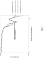
- FIG. 7 illustrates simulated irradiance retinal profiles for a standard monofocal IOL without edge scattering (e.g., with a smooth surface) and with various degrees of edge scattering.
- FIG. 8 illustrates simulated irradiance retinal profiles for a standard monofocal IOL with various edge thicknesses.
- FIG. 9 is an example computing device.
- FIG. 10 is a diagram of a ray-tracing depiction of an example physical eye model according to an implementation described herein.
- Ranges may be expressed herein as from “about” one particular value, and/or to “about” another particular value. When such a range is expressed, an aspect includes from the one particular value and/or to the other particular value. Similarly, when values are expressed as approximations, by use of the antecedent “about,” it will be understood that the particular value forms another aspect. It will be further understood that the endpoints of each of the ranges are significant both in relation to the other endpoint, and independently of the other endpoint. While implementations are described for intraocular lenses, it will become evident to those skilled in the art that the implementations are not limited thereto, but are applicable for other ophthalmic lenses.
- the terms “light” or “visible light” mean electromagnetic radiation within the visible waveband, for example, electromagnetic radiation with a wavelength in a vacuum that is between 390 nanometers and 780 nanometers.
- the term “optical power” of a lens or optic means the ability of the lens or optic to converge or diverge light to provide a focus (real or virtual) when disposed within a media having a refractive index of 1.336 (generally considered to be the refractive index of the aqueous and vitreous humors of the human eye), and is specified in reciprocal meters or Diopters (D). See ISO 11979-2.
- focus or “focal length” of a lens or optic is the reciprocal of the optical power.
- power of a lens or optic means optical power. Except where noted otherwise, optical power (either absolute or add power) of an intraocular lens or associated optic is from a reference plane associated with the lens or optic (e.g., a principal plane of an optic).
- the term “near vision” means vision produced by an eye that allows a subject to focus on objects that are at a distance of 40 cm or closer to a subject, typically within a range of 25 cm to 33 cm from the subject, which corresponds to a distance at which a subject would generally place printed material for the purpose of reading.
- the term “intermediate vision” means vision produced by an eye that allows a subject to focus on objects that are located between 40 cm and 2 meters from the subject.
- the term “distant vision” means vision produced by an eye that allows a subject to focus on objects that are at a distance that is greater than 2 meters, typically at a distance of about 5 meters from the subject, or at a distance of about 6 meters from the subject, or greater.
- FIG. 1 A a cross-sectional view of a phakic eye containing the natural crystalline lens is shown in which an eye 10 includes a retina 12 that receives light in the form of an image produced when light from an object is focused by the combination of the optical powers of a cornea 14 and a natural crystalline lens 16 .
- the cornea 14 and lens 16 are generally disposed about an optical axis (OA).
- OA optical axis
- the natural lens 16 is enclosed within a capsular bag 20 , which is a thin membrane attached to a ciliary muscle 22 via zonules 24 .
- An iris 26 disposed between the cornea 14 and the natural lens 16 , provides a variable pupil that dilates under lower lighting conditions (mesopic or scotopic vision) and constricts under brighter lighting conditions (photopic vision).
- the ciliary muscle 22 via the zonules 24 , controls the shape and position of the natural lens 16 , allowing the eye 10 to focus on both distant and near objects.
- the intraocular lens 100 can include an optic 102 and haptics 103 , the haptics 103 being configured to at least generally center the optic 102 within the capsular bag 20 , provide transfer of ocular forces to the optic 102 , and the like.
- Numerous configurations of haptics 103 relative to optic 102 are well known within the art, and the optics edge designs described herein can generally include any of these haptic configurations.
- this disclosure contemplates that the methods described herein can be used to evaluate any IOL independently of the haptics configuration and/or optics design.
- a computing device e.g., computing device 900 as described with respect to FIG. 9
- this disclosure contemplates that the operations can be performed with optical design software running on a computing device.
- OPTICSTUDIO from Zemax, LLC of Kirkland, Wash.
- OSLO from Lambda Research Corporation of Littleton, Mass. are examples of optical design software.
- NSC non-sequential
- the objects e.g., ophthalmic lens, pupil of the eye, etc.
- the objects that rays hit are determined by the physical positions of the objects, characteristics of the objects, and/or directions of the rays.
- a ray may hit some objects, even multiple times, while missing other objects. This is in contrast to sequential ray tracing, where every ray passes through the same objects and in the same order. Sequential and non-sequential ray-tracing are known in the art and are therefore not described in further detail herein.
- the ophthalmic lens can optionally be an intraocular lens. Although an intraocular lens is used in the examples below, it should be understood that the methods described herein are applicable to other ophthalmic lenses.
- the ophthalmic lens can be modeled as a three-dimensional (3D) object.
- a 3D model of the ophthalmic lens can be generated as a 3D computer aided design (CAD) object.
- CAD computer aided design
- the position or orientation of the 3D object within the eye model can be adjusted.
- An example NSC ray-tracing model of the eye with an intraocular lens 302 is shown in FIG. 3 .
- the NSC ray-tracing model of FIG. 3 includes the cornea 304 , pupil 306 , retina 308 , and sclera 310 .
- a sequential ray-tracing model of the eye can be constructed with and validated against individualized biometrical patient data.
- individualized biometrical data can include, but is not limited to, pupil size, anterior chamber depth, distance iris—IOL, axial length, anterior corneal topography, IOL tilt and decentration, and post-operative refractive errors.
- One example sequential ray-tracing eye model is the Liou-Brennan human eye model.
- the Liou-Brennan human eye model is only provided as an example, and it should be understood that other sequential eye models such as the TECNIS Chromatic Eye model from JOHNSON & JOHNSON of New Brunswick, N.J. can be used.
- the NSC ray-tracing model of the eye with an ophthalmic lens can be constructed (e.g., step 202 ).
- a light source and a detector can be modelled.
- the light source 312 can be a wide angle high divergence mono or polychromatic light source.
- the light source 312 is shown in the NSC ray-tracing model of FIG. 3 .
- This disclosure contemplates that the modelled light source can be another type of light source including, but not limited to a collimated light source positioned at certain eccentricity.
- the light source 312 can illuminate the detector.
- the detector can be a spherical or aspherical detector (discretized in Cartesian or polar coordinates). For example, the detector can mimic the retinal shape by means of an aspheric equation or a toric aspheric equation.
- the angular extent of the detector can optionally match the peripheral location of ora serrata or the quadrantic visual field limits, and the pixel size of the detector can optionally be smaller than the peripheral sampling of the photoreceptors.
- the detector can optionally have greater than 90 degrees maximum extent with less than 2.5 degrees pixel size in both azimuthal and radial directions.
- the detector can optionally account for retinal asymmetries between different meridians such as the vertical and the horizontal meridians (e.g., by defining the detector using a toric aspheric equation).
- This disclosure contemplates that the modelled detector can have characteristics other than those above, which are only provided only as examples.
- irradiance data can be computed.
- irradiance data can be simulated using the modelled light source and detector, as well as the NSC ray-tracing model (e.g., as shown by FIG. 3 ).
- Irradiance data can be computed for each of a plurality of pupil sizes (e.g., for different pupil sizes).
- Irradiance data can include, but is not limited to, an irradiance map and/or a cross-sectional irradiance profile.
- FIG. 4 illustrates example retinal irradiance maps and cross-sectional irradiance profiles computed as described above.
- cross-sectional irradiance profile can be used for deriving quantitative information (also referred to herein as “figures of merit”) including, but not limited to, ND angular location, ND angular width, local contrast, and local area of the reciprocal irradiance.
- ND can be evaluated by analyzing the irradiance data.
- this can include analyzing the figures of merit described above, e.g., the quantitative information derived from a cross-sectional irradiance profile.
- this can include determining a retinal illumination gap between light refracted by the ophthalmic lens and light refracted only by a cornea of the eye. The analysis can be performed on the respective irradiance data for each of the pupil sizes. Due to the pinhole effect, smaller pupils are associated with a higher incidence of ND complaints. For example, when using a standard monofocal IOL, FIG.
- NSC eye-model retains its clinical relevance in terms of angular location of ND (e.g., approximately 75 degrees) and ND dependency with pupil size (e.g., optical errors determine larger ray deviations filling the retinal illumination gap).
- irradiance data computations described above are conducted using a rotationally symmetric eye model (e.g., the NSC ray-tracing model shown in FIG. 3 ).
- a rotationally symmetric eye model e.g., the NSC ray-tracing model shown in FIG. 3 .
- Such a model neglects the visual field limiting impact of surrounding bone structures (e.g., supraorbital margin, nasal and zygomatic bones) of the subject such as a human being.
- irradiance data is obtained for all of the temporal, nasal, inferior, and superior visual fields.
- the monocular visual field limits for a human being are about: 90° temporal, 60° nasal, 70° inferior, and 50° superior. Millodot, M., Dictionary of Optometry and Visual Science , Oxford: Butterworth-Heinemann, 4 th ed., 1997.
- the temporal visual field is the only quadrant having an extent larger than the angular location of ND (e.g., about 75 degrees).
- the irradiance data in the temporal visual field can be analyzed.
- the irradiance data in one or more of the nasal, inferior, and superior visual fields can be ignored if surrounding bone structures limit the extent in these quadrants such that ND may not be detected by the subject in these quadrants.
- the edges of IOLs can be roughened to various extents during manufacturing, which promotes light scattering. Roughening depends on the manufacturer and fabrication method.
- the edge frosting effect can be retro-fitted by a Lambertian scattering surface to measurements performed by means of an off-axis modulation transfer function (MTF) bench, a physical wide angle eye model fitted with an IOL (e.g., the physical eye model shown in FIG. 10 ), and a charge-coupled device (CCD) camera.
- FIG. 5 illustrates edge scattering modelling results where the Lambertian scattering coefficient (a) is retro-fitted to measurements.
- ND profiles of various IOL mechanical platform designs are described. Across manufacturers, while the optic edge designs differ (e.g., surface roughness, thickness, IOL material refractive index, etc.), existing IOL mechanical platforms tend to be characterized by relatively similar geometries, for example, optic diameter of about 6 mm, total diameter between about 12.5-13.0 mm, and haptic loop designs.
- FIG. 6 the ND profiles for three commercially available example IOL platforms are shown. The commercially available platforms are labeled standard monofocal, “Example 1” 602 , “Example 2” 604 , and “Example 3” 606 .
- FIG. 6 shows that in identical biometrical conditions, these similar IOL mechanical platforms designs with different edge designs are characterized by similar ND profiles. In FIG. 6 , all of the simulations used the same Lambertian edge scattering coefficient (a).
- the methods described herein can be used to evaluate a plurality of ophthalmic lens designs, where each design is configured with a different degree of edge scattering. Using the results of such evaluation, an ophthalmic lens design that reduces ND can be selected. For example, a respective NSC ray-tracing model of the eye with each of a plurality of ophthalmic lenses, where each of the ophthalmic lenses is configured for a different degree of edge scattering, can be constructed. Thereafter, irradiance data can be computed as described herein and using each of the respective NSC ray-tracing models. This data can be analyzed to evaluate ND, and an ophthalmic lens design that reduces ND can be selected. This disclosure contemplates that ophthalmic lenses having the selected design can then be manufactured.
- the methods described herein can be used to evaluate a plurality of ophthalmic lens designs, where each design has a different edge thickness. Using the results of such evaluation, an ophthalmic lens design that reduces ND can be selected. For example, a respective NSC ray-tracing model of the eye with each of a plurality of ophthalmic lenses, where each of the ophthalmic lenses has a different edge thickness, can be constructed. Thereafter, irradiance data can be computed as described herein and using each of the respective NSC ray-tracing models. This data can be analyzed to evaluate ND, and an ophthalmic lens design that reduces ND can be selected. This disclosure contemplates that ophthalmic lenses having the selected design can then be manufactured.
- the ophthalmic edge design can optionally be optimized for a given optics diameter.
- an objective of the evaluation is to reduce, and in some implementations, minimize the retinal illumination gap between light refracted by the ophthalmic lens and light refracted only by the cornea of the eye.
- the degree of edge scattering and/or the edge thickness can be increased to minimize the retinal illumination gap.
- the ophthalmic edge design can optionally be optimized for a given ophthalmic lens material.
- the degree of edge scattering and/or the edge thickness can be increased to minimize the retinal illumination gap.
- This disclosure contemplates that ophthalmic lenses having the optimal design can then be manufactured.
- the methods described herein can be used to design an ophthalmic lens edge, where the edge design is defined by the Lambertian scattering coefficient.
- an ophthalmic lens edge scatter that reduces ND can be selected for a given IOL platform.
- the ophthalmic lens edge scatter can be adjusted to reduce the retinal illumination gap between light refracted by the ophthalmic lens and light refracted only by a cornea of the eye.
- An ophthalmic lens edge design e.g., the Lambertian scattering coefficient
- reduces, and in some implementations minimizes, the retinal illumination gap can be selected. For example, in FIG.
- edge scattering coefficients e.g., the Lambertian scattering coefficient (a) in FIG. 5
- 2 ⁇ Lambertian scattering coefficient (a) Lambertian scattering coefficient (b)
- 3 ⁇ Lambertian scattering coefficient (a) Lambertian scattering coefficient (c)
- the edge of an IOL can be roughened by lathing/milling parameters, which include but are not limited to tool radius, feed rate, tool RPM, etc., and/or any other suitable fabrication process such as photo-lithography, printing, molding, embossing, spin coating, dry etching etc.
- the methods described herein can be used to design an ophthalmic lens edge, where the edge design is defined by the thickness.
- an ophthalmic lens edge thickness that reduces ND can be selected for a given IOL platform.
- the ophthalmic lens edge thickness can be adjusted to reduce the retinal illumination gap between light refracted by the ophthalmic lens and light refracted only by a cornea of the eye.
- An ophthalmic lens edge design e.g., the edge thickness
- the retinal illumination gap can be selected.
- FIG. 8 simulated irradiance retinal profiles for a standard monofocal IOL with various edge thicknesses are described.
- FIG. 8 illustrates the effect of a 70% IOL edge thickness increase on the ND profile.
- the simulated irradiance retinal profile for a standard monofocal IOL using the Lambertian scattering coefficient (a) in FIGS. 5 and 7
- the simulated irradiance retinal profile for a standard monofocal IOL with 70% increased edge thickness using the Lambertian scattering coefficient (c) in FIG. 7 ).
- the values of the Lambertian scattering coefficient and/or increased edge thickness used for the simulations in FIG. 8 are provided only as examples and that other values can be used.
- the logical operations described herein with respect to the various figures may be implemented (1) as a sequence of computer implemented acts or program modules (i.e., software) running on a computing device (e.g., the computing device described in FIG. 9 , (2) as interconnected machine logic circuits or circuit modules (i.e., hardware) within the computing device and/or (3) a combination of software and hardware of the computing device.
- a computing device e.g., the computing device described in FIG. 9
- the logical operations discussed herein are not limited to any specific combination of hardware and software.
- the implementation is a matter of choice dependent on the performance and other requirements of the computing device. Accordingly, the logical operations described herein are referred to variously as operations, structural devices, acts, or modules.
- an example computing device 900 upon which the methods described herein may be implemented is illustrated. It should be understood that the example computing device 900 is only one example of a suitable computing environment upon which the methods described herein may be implemented.
- the computing device 900 can be a well-known computing system including, but not limited to, personal computers, servers, handheld or laptop devices, multiprocessor systems, microprocessor-based systems, network personal computers (PCs), minicomputers, mainframe computers, embedded systems, and/or distributed computing environments including a plurality of any of the above systems or devices.
- Distributed computing environments enable remote computing devices, which are connected to a communication network or other data transmission medium, to perform various tasks.
- the program modules, applications, and other data may be stored on local and/or remote computer storage media.
- computing device 900 typically includes at least one processing unit 906 and system memory 904 .
- system memory 904 may be volatile (such as random access memory (RAM)), non-volatile (such as read-only memory (ROM), flash memory, etc.), or some combination of the two.
- RAM random access memory
- ROM read-only memory
- FIG. 9 dashed line 902 This most basic configuration is illustrated in FIG. 9 dashed line 902 .
- the processing unit 906 may be a standard programmable processor that performs arithmetic and logic operations necessary for operation of the computing device 900 .
- the computing device 900 may also include a bus or other communication mechanism for communicating information among various components of the computing device 900 .
- Computing device 900 may have additional features/functionality.
- computing device 900 may include additional storage such as removable storage 908 and non-removable storage 910 including, but not limited to, magnetic or optical disks or tapes.
- Computing device 900 may also contain network connection(s) 916 that allow the device to communicate with other devices.
- Computing device 900 may also have input device(s) 914 such as a keyboard, mouse, touch screen, etc.
- Output device(s) 912 such as a display, speakers, printer, etc. may also be included.
- the additional devices may be connected to the bus in order to facilitate communication of data among the components of the computing device 900 . All these devices are well known in the art and need not be discussed at length here.
- the processing unit 906 may be configured to execute program code encoded in tangible, computer-readable media.
- Tangible, computer-readable media refers to any media that is capable of providing data that causes the computing device 900 (i.e., a machine) to operate in a particular fashion.
- Various computer-readable media may be utilized to provide instructions to the processing unit 906 for execution.
- Example tangible, computer-readable media may include, but is not limited to, volatile media, non-volatile media, removable media and non-removable media implemented in any method or technology for storage of information such as computer readable instructions, data structures, program modules or other data.
- System memory 904 , removable storage 908 , and non-removable storage 910 are all examples of tangible, computer storage media.
- Example tangible, computer-readable recording media include, but are not limited to, an integrated circuit (e.g., field-programmable gate array or application-specific IC), a hard disk, an optical disk, a magneto-optical disk, a floppy disk, a magnetic tape, a holographic storage medium, a solid-state device, RAM, ROM, electrically erasable program read-only memory (EEPROM), flash memory or other memory technology, CD-ROM, digital versatile disks (DVD) or other optical storage, magnetic cassettes, magnetic tape, magnetic disk storage or other magnetic storage devices.
- an integrated circuit e.g., field-programmable gate array or application-specific IC
- a hard disk e.g., an optical disk, a magneto-optical disk, a floppy disk, a magnetic tape, a holographic storage medium, a solid-state device, RAM, ROM, electrically erasable program read-only memory (EEPROM), flash memory or other memory technology, CD-ROM, digital versatile disks (
- the processing unit 906 may execute program code stored in the system memory 904 .
- the bus may carry data to the system memory 904 , from which the processing unit 906 receives and executes instructions.
- the data received by the system memory 904 may optionally be stored on the removable storage 908 or the non-removable storage 910 before or after execution by the processing unit 906 .
- the various techniques described herein may be implemented in connection with hardware or software or, where appropriate, with a combination thereof.
- the methods and apparatuses of the presently disclosed subject matter, or certain aspects or portions thereof may take the form of program code (i.e., instructions) embodied in tangible media, such as floppy diskettes, CD-ROMs, hard drives, or any other machine-readable storage medium wherein, when the program code is loaded into and executed by a machine, such as a computing device, the machine becomes an apparatus for practicing the presently disclosed subject matter.
- the computing device In the case of program code execution on programmable computers, the computing device generally includes a processor, a storage medium readable by the processor (including volatile and non-volatile memory and/or storage elements), at least one input device, and at least one output device.
- One or more programs may implement or utilize the processes described in connection with the presently disclosed subject matter, e.g., through the use of an application programming interface (API), reusable controls, or the like.
- API application programming interface
- Such programs may be implemented in a high level procedural or object-oriented programming language to communicate with a computer system.
- the program(s) can be implemented in assembly or machine language, if desired. In any case, the language may be a compiled or interpreted language and it may be combined with hardware implementations.
- This disclosure contemplates creating a physical eye model (e.g., a model that mimics the aphakic eye) including an ophthalmic lens.
- the physical eye model can be created based on the ophthalmic lens as evaluated according to any of the methods described herein.
- the ophthalmic lens is an IOL.
- the physical eye model can further include a cornea, a pupil, a holder for the ophthalmic lens, a light source, and/or an electronic light sensor. An example physical eye model is described below with regard to FIG. 10 .
- Characteristic(s) of the physical eye model can resemble optical characteristic(s) of the NSC ray-tracing model and/or the modelled light source described above with regard to FIGS. 2 and 3 .
- Characteristics of the physical eye model can include, but are not limited to, cornea shape, ophthalmic lens dimensions, pupil and ophthalmic lens positioning, as well as characteristic(s) of the light source and/or light sensor.
- characteristic(s) of the cornea, the pupil, and/or the ophthalmic lens can resemble optical characteristic(s) of the NSC ray-tracing model shown in FIG. 3
- characteristic(s) of the light source and/or the light sensor can resemble optical characteristic(s) of the modeled light source or modeled detector described above with regard to FIGS. 2 and 3 .
- This disclosure contemplates indirectly measuring edge frosting effect of an ophthalmic lens. For example, it is possible to obtain measurements using an off-axis modulation transfer function (MTF) bench, the physical eye model described herein, and an electronic light sensor. These measurements can be input into an NSC ray-tracing model (e.g., NSC ray-tracing model shown in FIG. 3 ). This method facilitates retro-fitting the edge frosting effect (e.g., the Lambertian scattering coefficient) through the NSC ray-tracing model.
- MTF off-axis modulation transfer function
- a set-up including a physical wide angle eye model can be constructed as depicted in FIG. 10 . It includes a cornea 1001 , a pupil 1002 , an IOL holder with the IOL 1003 , a back window 1004 and an electronic light sensor such as flat CCD camera 1005 .
- the physical eye model is a ray-tracing based design to enable in-vitro visualization and quantification of various photic events (PD and ND). For a given object angle, pupil size and IOL design and position, the image heights associated with both main and spurious secondary images are theoretically calculated through non-sequential ray-tracing (e.g., the NSC ray-tracing model shown in FIG. 3 ).
- a 3D CAD model of the IOL is used to account for its complete geometrical description.
- the native IOL field of curvature or a field of curvature giving an angular aberration profile identical to the one corresponding to the IOL placed in an individualized anatomical eye model with a unique or population averaged retinal shape (conicoid) could be used.
- the electronic light sensors can comprise charged-coupled devices (CCD), including both imaging CCDs and intensity CCDs.
- CCD charged-coupled devices
- CMOS complementary metal-oxide-semiconductor
- a wavefront sensor such as a Shack-Hartmann wavefront sensor could be used.
- interferometers, photomultiplier tube (PMT) sensors, or small and large angle microscope sensors can be used.
- the light sensor can detect light emitted by a light source (not shown in FIG. 10 ).
Landscapes
- Health & Medical Sciences (AREA)
- Engineering & Computer Science (AREA)
- Physics & Mathematics (AREA)
- Ophthalmology & Optometry (AREA)
- General Health & Medical Sciences (AREA)
- General Physics & Mathematics (AREA)
- Public Health (AREA)
- Theoretical Computer Science (AREA)
- Biomedical Technology (AREA)
- Medical Informatics (AREA)
- Vascular Medicine (AREA)
- Animal Behavior & Ethology (AREA)
- Computer Graphics (AREA)
- Veterinary Medicine (AREA)
- Life Sciences & Earth Sciences (AREA)
- Heart & Thoracic Surgery (AREA)
- Transplantation (AREA)
- Oral & Maxillofacial Surgery (AREA)
- Cardiology (AREA)
- Software Systems (AREA)
- Computer Vision & Pattern Recognition (AREA)
- Quality & Reliability (AREA)
- Optics & Photonics (AREA)
- Radiology & Medical Imaging (AREA)
- Nuclear Medicine, Radiotherapy & Molecular Imaging (AREA)
- Geometry (AREA)
- Chemical & Material Sciences (AREA)
- Combustion & Propulsion (AREA)
- Transportation (AREA)
- Mechanical Engineering (AREA)
- Data Mining & Analysis (AREA)
- Epidemiology (AREA)
- Primary Health Care (AREA)
- Pathology (AREA)
- Databases & Information Systems (AREA)
- Prostheses (AREA)
Priority Applications (1)
| Application Number | Priority Date | Filing Date | Title |
|---|---|---|---|
| US17/057,634 US11708128B2 (en) | 2018-11-30 | 2019-11-29 | Systems and methods for evaluating and reducing negative dysphotopsia |
Applications Claiming Priority (3)
| Application Number | Priority Date | Filing Date | Title |
|---|---|---|---|
| US201862773983P | 2018-11-30 | 2018-11-30 | |
| US17/057,634 US11708128B2 (en) | 2018-11-30 | 2019-11-29 | Systems and methods for evaluating and reducing negative dysphotopsia |
| PCT/EP2019/083179 WO2020109602A1 (fr) | 2018-11-30 | 2019-11-29 | Systèmes et procédés d'évaluation et de réduction de la dysphotopsie négative |
Related Parent Applications (1)
| Application Number | Title | Priority Date | Filing Date |
|---|---|---|---|
| PCT/EP2019/083179 A-371-Of-International WO2020109602A1 (fr) | 2018-11-30 | 2019-11-29 | Systèmes et procédés d'évaluation et de réduction de la dysphotopsie négative |
Related Child Applications (1)
| Application Number | Title | Priority Date | Filing Date |
|---|---|---|---|
| US18/355,835 Continuation US20230365227A1 (en) | 2018-11-30 | 2023-07-20 | Systems and methods for evaluating and reducing negative dysphotopsia |
Publications (2)
| Publication Number | Publication Date |
|---|---|
| US20210279939A1 US20210279939A1 (en) | 2021-09-09 |
| US11708128B2 true US11708128B2 (en) | 2023-07-25 |
Family
ID=68766753
Family Applications (2)
| Application Number | Title | Priority Date | Filing Date |
|---|---|---|---|
| US17/057,634 Active 2040-01-25 US11708128B2 (en) | 2018-11-30 | 2019-11-29 | Systems and methods for evaluating and reducing negative dysphotopsia |
| US18/355,835 Pending US20230365227A1 (en) | 2018-11-30 | 2023-07-20 | Systems and methods for evaluating and reducing negative dysphotopsia |
Family Applications After (1)
| Application Number | Title | Priority Date | Filing Date |
|---|---|---|---|
| US18/355,835 Pending US20230365227A1 (en) | 2018-11-30 | 2023-07-20 | Systems and methods for evaluating and reducing negative dysphotopsia |
Country Status (5)
| Country | Link |
|---|---|
| US (2) | US11708128B2 (fr) |
| EP (1) | EP3886675A1 (fr) |
| AU (1) | AU2019387436A1 (fr) |
| CA (1) | CA3100412A1 (fr) |
| WO (1) | WO2020109602A1 (fr) |
Citations (6)
| Publication number | Priority date | Publication date | Assignee | Title |
|---|---|---|---|---|
| US20050041203A1 (en) | 2003-08-20 | 2005-02-24 | Lindacher Joseph Michael | Ophthalmic lens with optimal power profile |
| US20060241751A1 (en) * | 2002-09-13 | 2006-10-26 | Marmo J C | Corneal onlays and methods of producing same |
| US20080269885A1 (en) | 2007-04-30 | 2008-10-30 | Simpson Michael J | IOL Peripheral Surface Designs to Reduce Negative Dysphotopsia |
| US20080269890A1 (en) | 2007-04-30 | 2008-10-30 | Alcon Universal Ltd. | Intraocular lens with peripheral region designed to reduce negative dysphotopsia |
| US20080269886A1 (en) * | 2007-04-30 | 2008-10-30 | Simpson Michael J | IOL Peripheral Surface Designs to Reduce Negative Dysphotopsia |
| WO2010100523A1 (fr) | 2009-03-05 | 2010-09-10 | Amo Regional Holdings | Lentille multizone avec profondeur de foyer étendue |
Family Cites Families (1)
| Publication number | Priority date | Publication date | Assignee | Title |
|---|---|---|---|---|
| CA3109979C (fr) * | 2016-10-21 | 2023-10-17 | Omega Ophthalmics Llc | Dispositifs capsulaires prothetiques |
-
2019
- 2019-11-29 CA CA3100412A patent/CA3100412A1/fr active Pending
- 2019-11-29 US US17/057,634 patent/US11708128B2/en active Active
- 2019-11-29 EP EP19813488.4A patent/EP3886675A1/fr active Pending
- 2019-11-29 WO PCT/EP2019/083179 patent/WO2020109602A1/fr unknown
- 2019-11-29 AU AU2019387436A patent/AU2019387436A1/en active Pending
-
2023
- 2023-07-20 US US18/355,835 patent/US20230365227A1/en active Pending
Patent Citations (6)
| Publication number | Priority date | Publication date | Assignee | Title |
|---|---|---|---|---|
| US20060241751A1 (en) * | 2002-09-13 | 2006-10-26 | Marmo J C | Corneal onlays and methods of producing same |
| US20050041203A1 (en) | 2003-08-20 | 2005-02-24 | Lindacher Joseph Michael | Ophthalmic lens with optimal power profile |
| US20080269885A1 (en) | 2007-04-30 | 2008-10-30 | Simpson Michael J | IOL Peripheral Surface Designs to Reduce Negative Dysphotopsia |
| US20080269890A1 (en) | 2007-04-30 | 2008-10-30 | Alcon Universal Ltd. | Intraocular lens with peripheral region designed to reduce negative dysphotopsia |
| US20080269886A1 (en) * | 2007-04-30 | 2008-10-30 | Simpson Michael J | IOL Peripheral Surface Designs to Reduce Negative Dysphotopsia |
| WO2010100523A1 (fr) | 2009-03-05 | 2010-09-10 | Amo Regional Holdings | Lentille multizone avec profondeur de foyer étendue |
Non-Patent Citations (7)
| Title |
|---|
| Curcio C, C., et al., "Human Photoreceptor Topography," The Journal of Comparative Neurology, 1990, vol. 292, pp. 497-523. |
| Curcio C.A., et al., "Topography of Ganglion Cells in Human Retina," The Journal of Comparative Neurology, 1990, vol. 300, pp. 5-25. |
| Holladay J.T., et al., "Negative Dysphotopsia: The Enigmatic Penumbra," Journal Cataract and Refractive Surgery, Jan. 2012, vol. 38 (7), pp. 1251-1265. |
| Hong X.,et al,"Ray-Tracing Optical Modeling of Negative Dysphotopsia," Journal of Biomedical Optics, Dec. 2011, vol. 16(12), pp. 125001. |
| International Search Report and written opinion for Application No. PCT/EP2019/078555, dated Mar. 30, 2020, 12 pages. |
| International Search Report and Written Opinion for Application No. PCT/EP2019/083179, dated Feb. 6, 2020, 14 pages. |
| Spector R.H., "Chapter 116 Visual Fields Figure 116.1" Clinical Methods: The History, Physical, and Laboratory Examinations, 3rd Edition Walker HK, Hall WD, Hurst JW 1990, Retrieved from the Internet: (https://www.ncbi.nlm.nih.gov/books/NBK220/), 8 Pages. |
Also Published As
| Publication number | Publication date |
|---|---|
| EP3886675A1 (fr) | 2021-10-06 |
| US20230365227A1 (en) | 2023-11-16 |
| CA3100412A1 (fr) | 2020-06-04 |
| WO2020109602A1 (fr) | 2020-06-04 |
| US20210279939A1 (en) | 2021-09-09 |
| AU2019387436A1 (en) | 2020-12-03 |
Similar Documents
| Publication | Publication Date | Title |
|---|---|---|
| Holladay et al. | Negative dysphotopsia: causes and rationale for prevention and treatment | |
| JP5367849B2 (ja) | 眼内レンズを選択するコンピュータシステム | |
| US8657445B2 (en) | System and method for determining and predicting IOL power in situ | |
| Simpson | Mini-review: Far peripheral vision | |
| KR102035182B1 (ko) | 직접 결정된 iol 위치에 따른 인공 수정체 (iol)도수 연산 | |
| CN1430495A (zh) | 获得能减少眼像差的眼科透镜的方法 | |
| GB2488802A (en) | Predicting the post-operative position of a replacement intraocular lens | |
| JP2007510521A (ja) | 光学収差補正のためのマルチゾーン眼内レンズ | |
| US20130282116A1 (en) | Apparatus, system and method to account for spherical aberration at the iris plane in the design of an intraocular lens | |
| CA2877234A1 (fr) | Lentille comportant une profondeur de foyer etendue et procede associe a celle-ci | |
| Olsen et al. | Ray-tracing analysis of the corneal power from Scheimpflug data | |
| US10987213B2 (en) | Method for selecting an IOL on the basis of the prediction of the anatomical, post-operative position and orientation thereof | |
| JP2018118071A (ja) | 眼球構造をモデリングするための装置 | |
| US11708128B2 (en) | Systems and methods for evaluating and reducing negative dysphotopsia | |
| AU2020211108A1 (en) | Systems and methods for intraocular lens selection using emmetropia zone prediction | |
| Gillner et al. | Automatic intraocular lens segmentation and detection in optical coherence tomography images | |
| KR20210113143A (ko) | 렌즈 결정 방법 및 이를 이용하는 장치 | |
| US8321184B1 (en) | Method for characterizing lenses | |
| Denion et al. | The sclerotic scatter limbal arc is more easily elicited under mesopic rather than photopic conditions | |
| US20180153683A1 (en) | Iol with reduced pupillary reflections | |
| EP3073898B1 (fr) | Système et procédé pour mesurer une dysphotopsie | |
| WO2013159076A2 (fr) | Systèmes et procédés d'amélioration de la vue | |
| KR102323355B1 (ko) | 볼팅값 예측 방법 및 이를 이용하는 장치 | |
| US20220183547A1 (en) | Prediction of post-operative vignetting in a pseudophakic eye | |
| Yang | Analysis of smartphone images for vision screening of refractive errors |
Legal Events
| Date | Code | Title | Description |
|---|---|---|---|
| FEPP | Fee payment procedure |
Free format text: ENTITY STATUS SET TO UNDISCOUNTED (ORIGINAL EVENT CODE: BIG.); ENTITY STATUS OF PATENT OWNER: LARGE ENTITY |
|
| AS | Assignment |
Owner name: AMO GRONINGEN B.V., NETHERLANDS Free format text: ASSIGNMENT OF ASSIGNORS INTEREST;ASSIGNORS:STATE, MIHAI;ROSEN, ROBERT;MEIJER, SIEGER;AND OTHERS;SIGNING DATES FROM 20191108 TO 20191114;REEL/FRAME:055135/0025 |
|
| STPP | Information on status: patent application and granting procedure in general |
Free format text: DOCKETED NEW CASE - READY FOR EXAMINATION |
|
| STPP | Information on status: patent application and granting procedure in general |
Free format text: NON FINAL ACTION MAILED |
|
| STPP | Information on status: patent application and granting procedure in general |
Free format text: RESPONSE TO NON-FINAL OFFICE ACTION ENTERED AND FORWARDED TO EXAMINER |
|
| STPP | Information on status: patent application and granting procedure in general |
Free format text: PUBLICATIONS -- ISSUE FEE PAYMENT VERIFIED |
|
| STCF | Information on status: patent grant |
Free format text: PATENTED CASE |