US11698281B2 - Real-time measurement of two-phase mass flow rate and enthalpy using pressure differential devices - Google Patents
Real-time measurement of two-phase mass flow rate and enthalpy using pressure differential devices Download PDFInfo
- Publication number
- US11698281B2 US11698281B2 US17/017,008 US202017017008A US11698281B2 US 11698281 B2 US11698281 B2 US 11698281B2 US 202017017008 A US202017017008 A US 202017017008A US 11698281 B2 US11698281 B2 US 11698281B2
- Authority
- US
- United States
- Prior art keywords
- enthalpy
- pressure
- real
- flow rate
- mass flow
- Prior art date
- Legal status (The legal status is an assumption and is not a legal conclusion. Google has not performed a legal analysis and makes no representation as to the accuracy of the status listed.)
- Active, expires
Links
Images


Classifications
-
- G—PHYSICS
- G01—MEASURING; TESTING
- G01F—MEASURING VOLUME, VOLUME FLOW, MASS FLOW OR LIQUID LEVEL; METERING BY VOLUME
- G01F1/00—Measuring the volume flow or mass flow of fluid or fluent solid material wherein the fluid passes through a meter in a continuous flow
- G01F1/74—Devices for measuring flow of a fluid or flow of a fluent solid material in suspension in another fluid
-
- F—MECHANICAL ENGINEERING; LIGHTING; HEATING; WEAPONS; BLASTING
- F24—HEATING; RANGES; VENTILATING
- F24T—GEOTHERMAL COLLECTORS; GEOTHERMAL SYSTEMS
- F24T50/00—Geothermal systems
-
- G—PHYSICS
- G01—MEASURING; TESTING
- G01F—MEASURING VOLUME, VOLUME FLOW, MASS FLOW OR LIQUID LEVEL; METERING BY VOLUME
- G01F1/00—Measuring the volume flow or mass flow of fluid or fluent solid material wherein the fluid passes through a meter in a continuous flow
- G01F1/05—Measuring the volume flow or mass flow of fluid or fluent solid material wherein the fluid passes through a meter in a continuous flow by using mechanical effects
- G01F1/34—Measuring the volume flow or mass flow of fluid or fluent solid material wherein the fluid passes through a meter in a continuous flow by using mechanical effects by measuring pressure or differential pressure
- G01F1/36—Measuring the volume flow or mass flow of fluid or fluent solid material wherein the fluid passes through a meter in a continuous flow by using mechanical effects by measuring pressure or differential pressure the pressure or differential pressure being created by the use of flow constriction
- G01F1/363—Measuring the volume flow or mass flow of fluid or fluent solid material wherein the fluid passes through a meter in a continuous flow by using mechanical effects by measuring pressure or differential pressure the pressure or differential pressure being created by the use of flow constriction with electrical or electro-mechanical indication
-
- G—PHYSICS
- G01—MEASURING; TESTING
- G01F—MEASURING VOLUME, VOLUME FLOW, MASS FLOW OR LIQUID LEVEL; METERING BY VOLUME
- G01F1/00—Measuring the volume flow or mass flow of fluid or fluent solid material wherein the fluid passes through a meter in a continuous flow
- G01F1/05—Measuring the volume flow or mass flow of fluid or fluent solid material wherein the fluid passes through a meter in a continuous flow by using mechanical effects
- G01F1/34—Measuring the volume flow or mass flow of fluid or fluent solid material wherein the fluid passes through a meter in a continuous flow by using mechanical effects by measuring pressure or differential pressure
- G01F1/36—Measuring the volume flow or mass flow of fluid or fluent solid material wherein the fluid passes through a meter in a continuous flow by using mechanical effects by measuring pressure or differential pressure the pressure or differential pressure being created by the use of flow constriction
- G01F1/40—Details of construction of the flow constriction devices
- G01F1/42—Orifices or nozzles
-
- G—PHYSICS
- G01—MEASURING; TESTING
- G01F—MEASURING VOLUME, VOLUME FLOW, MASS FLOW OR LIQUID LEVEL; METERING BY VOLUME
- G01F1/00—Measuring the volume flow or mass flow of fluid or fluent solid material wherein the fluid passes through a meter in a continuous flow
- G01F1/05—Measuring the volume flow or mass flow of fluid or fluent solid material wherein the fluid passes through a meter in a continuous flow by using mechanical effects
- G01F1/34—Measuring the volume flow or mass flow of fluid or fluent solid material wherein the fluid passes through a meter in a continuous flow by using mechanical effects by measuring pressure or differential pressure
- G01F1/36—Measuring the volume flow or mass flow of fluid or fluent solid material wherein the fluid passes through a meter in a continuous flow by using mechanical effects by measuring pressure or differential pressure the pressure or differential pressure being created by the use of flow constriction
- G01F1/40—Details of construction of the flow constriction devices
- G01F1/44—Venturi tubes
-
- G—PHYSICS
- G01—MEASURING; TESTING
- G01F—MEASURING VOLUME, VOLUME FLOW, MASS FLOW OR LIQUID LEVEL; METERING BY VOLUME
- G01F1/00—Measuring the volume flow or mass flow of fluid or fluent solid material wherein the fluid passes through a meter in a continuous flow
- G01F1/76—Devices for measuring mass flow of a fluid or a fluent solid material
- G01F1/86—Indirect mass flowmeters, e.g. measuring volume flow and density, temperature or pressure
- G01F1/88—Indirect mass flowmeters, e.g. measuring volume flow and density, temperature or pressure with differential-pressure measurement to determine the volume flow
-
- G—PHYSICS
- G01—MEASURING; TESTING
- G01K—MEASURING TEMPERATURE; MEASURING QUANTITY OF HEAT; THERMALLY-SENSITIVE ELEMENTS NOT OTHERWISE PROVIDED FOR
- G01K17/00—Measuring quantity of heat
- G01K17/06—Measuring quantity of heat conveyed by flowing media, e.g. in heating systems e.g. the quantity of heat in a transporting medium, delivered to or consumed in an expenditure device
-
- F—MECHANICAL ENGINEERING; LIGHTING; HEATING; WEAPONS; BLASTING
- F24—HEATING; RANGES; VENTILATING
- F24T—GEOTHERMAL COLLECTORS; GEOTHERMAL SYSTEMS
- F24T10/00—Geothermal collectors
- F24T2010/50—Component parts, details or accessories
-
- Y—GENERAL TAGGING OF NEW TECHNOLOGICAL DEVELOPMENTS; GENERAL TAGGING OF CROSS-SECTIONAL TECHNOLOGIES SPANNING OVER SEVERAL SECTIONS OF THE IPC; TECHNICAL SUBJECTS COVERED BY FORMER USPC CROSS-REFERENCE ART COLLECTIONS [XRACs] AND DIGESTS
- Y02—TECHNOLOGIES OR APPLICATIONS FOR MITIGATION OR ADAPTATION AGAINST CLIMATE CHANGE
- Y02E—REDUCTION OF GREENHOUSE GAS [GHG] EMISSIONS, RELATED TO ENERGY GENERATION, TRANSMISSION OR DISTRIBUTION
- Y02E10/00—Energy generation through renewable energy sources
- Y02E10/10—Geothermal energy
Definitions
- Geothermal and thermal fluids which are utilized and used to produce electricity is related to the energy carried on and transferred by two-phase fluid flow ( 2 ), steam and liquid from reservoir or boiler to power plants.
- the measurement of two-phase fluids becomes very important in the geothermal and thermal industries as it relates to plant management and performance monitoring ( 1 ) on a geothermal field.
- the parameters that are very important to be measured in real-time during the operation of geothermal wells are the mass flow rate ( 14 ) and enthalpy ( 12 ). By conducting continuous measurements on both parameters, the problem and performance of geothermal wells ( 1 ) or other thermal plants can be identified and mitigated quickly and accurately.
- the consequence of the centralized separation model is the inability to measure the mass flow rate ( 14 ) and enthalpy ( 12 ) in real-time on every geothermal well ( 1 ) or above the ground pipeline individually. This is because the connected two-phase fluid pipe ( 5 ) becomes a single line to the separator. The fluid in the separator comes from a number of supplying geothermal wells so the mass flow rate ( 14 ) and enthalpy ( 12 ) is the mixing result of these wells.
- Inventions on this patent present a combined method and measuring instrument ( 6 , 7 ) which is used to measure the mass flow rate ( 14 ) and enthalpy ( 12 ) of two-phase fluid from geothermal pipelines in real-time, with a relative error value below one percent.
- the measuring instrument method ( 6 , 7 ) is developed using a pressure differential measurement approach which is the difference between the measured pressure on the upstream ( 3 ) and downstream sides ( 4 ) of several pressure measuring points through a series of experimental tests in some geothermal above the ground pipelines ( 2 - 3 ). From this measuring instrument ( 6 , 7 ), three values of the upstream-downstream pressure differences are recorded ( 8 - 10 ).
- This invention relates to methods and measuring instruments ( 6 , 7 ) to derive the value of mass flow rates ( 14 ) and enthalpy ( 12 ) of two-phase fluid simultaneously, continuously, and in real-time that have a low relative error ( ⁇ 1%).
- the measuring instrument is installed in a two-phase above the ground pipeline ( 5 ).
- a particular component that is in this invention can be an orifice plate ( FIG. 4 ), a Nozzle ( FIG. 5 ) or Venturi tube ( FIG. 6 ) is installed in any two-phase above the ground pipeline ( 5 ).
- This particular component will provide a restriction and disturbance effect on the flow of two-phase fluids, causing a change in the speed and pressure of two-phase fluid within the above ground pipeline.
- the changes in the two-phase fluid pressure on the upstream ( 3 ) and downstream sides ( 4 ) are converted and calculated to derive the mass flow rate ( 14 ).
- the mass flow rate ( 14 ) In order to calculate the mass flow rate ( 14 ), the value of the two-phase fluid enthalpy needs to be known.
- the value of pressure difference between the upstream ( 3 ) and the downstream sides ( 4 ) of the measuring instrument components ( 6 , 7 ) mounted on the two-phase pipe ( 5 ) have a correlation with the two-phase fluid enthalpy.
- the enthalpy in real-time ( 12 ) can be obtained.
- the values of real-time enthalpy, pressure difference data ( 10 ) and mass flow rate estimate ( 13 ) are used as inputs in the equation algorithms to obtain the mass flow rate ( 14 ) in real-time.
- the main purpose of this invention is to provide a method and measuring instrument ( 6 , 7 ) which has the ability to measure the mass flow rate ( 14 ) and enthalpy ( 12 ) simultaneously and continuously.
- the currently available two-phase fluid measurement methods such as horizontal lip pipes, separators, tracer flow testing, calorimeter, radio frequency, load cells, and ultrasonic flow meters, it cannot perform real-time measurements of mass flow rate ( 14 ) and enthalpy ( 12 ) of two-phase fluids from geothermal above the ground pipelines.
- the pressure signal generated from the flow and pressure barrier component ( FIGS. 3 - 6 ) is transmitted from the transmitter and the transducer via a cable or wireless to the control room of the power plant which is then converted and computerized to derive the mass flow rate ( 14 ) and enthalpy ( 12 ).
- the mass flow rate ( 14 ) and enthalpy ( 12 ) data as a function of time are then stored in the memory of the computer and can be made available when needed for analysis.
- the instrumentation equipment is adjusted so that it can be installed and dismantled easily.
- FIG. 1 is a simple schematic diagram of the two-phase fluid utilization from a geothermal well.
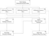
- FIG. 2 is a flowchart of the method of measuring mass flow rate and enthalpy of two-phase fluid of a geothermal above the ground pipeline in real-time.
- FIG. 3 is a top-view schematic diagram of the measuring instrument of mass flow rate and enthalpy of a geothermal well or a above the ground pipeline two-phase fluid flow with the multi-taping orifice plate type.
- FIG. 4 is the orifice plate type: (a) concentric, (b) bottom eccentric, (c) top eccentric, and (d) segmental designs.
- FIG. 5 is a top-view schematic diagram of the measuring instrument of mass flow rate and enthalpy of a geothermal well or a above the ground pipeline two-phase fluid flow with the multi-taping Nozzle type.
- FIG. 6 is a top-view schematic diagram of the mass flow rate and enthalpy of the two-phase fluid flow of a geothermal well or the above ground pipeline with the Venturi tube multi-taping type.
- FIG. 7 is a comparison of the measurement results using the measuring instrument of mass flow rate gauge and enthalpy with real-time field data.
- the measuring instruments ( 6 , 7 ) of mass flow rate which are often used in the industry, employ a method which measures the difference between upstream ( 3 ) and downstream pressures ( 4 ).
- the principle of this measuring instrument ( 6 , 7 ) refers to the energy conversion theory in the fluid flowing inside the closed above ground pipeline ( 5 ).
- the measuring instruments ( 6 , 7 ) of pressure difference devices consist of primary and secondary components.
- the primary component is installed in the pipeline ( 5 ) for restricting flow and will cause the pressure difference between upstream ( 3 ) and downstream ( 4 ).
- the value of pressure difference from the measuring instrument ( 6 , 7 ) is used to calculate the fluid mass flow rate ( 14 ) by applying the Bernoulli law.
- the secondary component is connected to the measuring instrumentation to provide information on the calculation variable of mass flow rates, such as pressure and temperature. Both the primary and secondary components can be installed as one unit or separated from the measuring instrument system ( 6 ).
- the measuring instrument of pressure difference includes orifice plates ( FIGS. 3 - 4 ), Nozzle ( FIG. 5 ) and a Venturi tube ( FIG. 6 ).
- the installation of pressure difference measuring instruments ( 6 , 7 ) on the above the ground pipeline ( 1 , 5 ) can be seen in FIG. 1 .
- the recommended installation for the measuring instruments ( 1 ) is that it is installed on a straight, unhindered pipe ( 5 ) with a minimum distance of 20 times the pipe inside diameter ( 26 ) on the upstream side ( 3 ) and 7 times the pipe inside diameter ( 26 ) on the downstream side ( 4 ).
- the longer the straight pipe distance ( 5 ) the smaller the error in the measurement results because the flow disturbance effects caused by pipe fittings, such as valve, reducer and elbow, can be minimized.
- the multi-pressure tapings ( 16 - 21 , 32 - 37 , 42 - 47 ) are installed into a single unit with the measuring instrument ( 6 , 7 ).
- the pressure at that point is referred to as the upstream pressure ( 16 - 18 , 32 - 34 , 42 - 44 ).
- the two-phase fluid velocity will increase due to the narrowing area at the primary component ( 25 , 41 , 52 ) so that it causes the pressure decrease in the downstream side ( 19 - 21 , 35 - 37 , 45 - 47 ).
- the difference between the upstream ( 16 - 18 , 32 - 34 , 42 - 44 ) and downstream pressures ( 19 - 21 , 35 - 37 , 45 - 47 ) is called a pressure difference, which is measured by the pressure transducer or gauge.
- the pressure difference will increase and decrease following the change in the mass flow rate ( 14 ) and enthalpy ( 12 ) in the above ground pipeline ( 5 ).
- upstream pressure values 16 - 18 , 32 - 34 , 42 - 44
- downstream pressure values 19 - 21 , 35 - 37 , 45 - 47
- pressure difference values 22 - 24 , 38 - 40 , 48 - 50
- the system is called as multi-tapping. All measured values of the multi-tapping (upstream pressure, downstream pressure, and pressure difference) are correlated with enthalpy ( 12 ) and mass flow rate ( 14 ). Signals of multi-tapping pressure difference ( 22 - 24 , 38 - 40 , 48 - 50 ) are measured by the transmitters from the primary components ( 25 , 41 , 52 ).
- the signal from the transmitters is converted into electrical signals, which are processed and calculated in a computer to get the enthalpy.
- the noise of the resulting enthalpy is reduced by adding an input of enthalpy estimate value ( 11 ) and is reduced using the Kalman filter technique.
- the real-time enthalpy ( 12 ) is obtained and optimized from the results.
- the real-time enthalpy ( 12 ) and the real-time data of multi-tapping pressure differences ( 22 - 24 , 38 - 40 , 48 - 50 ) are used to calculate the mass flow rate. Noise in the measured mass flow rate is also reduced by using the Kalman filter technique.
- the algorithm of real-time measurement process of enthalpy ( 12 ) and mass flow rate ( 14 ) are presented in the following equation ( FIG. 2 ):
- h K h ( h f ⁇ ( p u ) + xh f ⁇ g ⁇ ( p u ) ) m .
- t K m ( p u p d ) D ⁇ 10 - 5 ⁇ ⁇ ⁇ p D ⁇ ( ⁇ ⁇ d 2 4 ) ⁇ ( 9 ⁇ 10 5 ⁇ h - 2 ) ⁇ 2 ⁇ ⁇ ⁇ p 1 - ⁇ 4
- h is the two-phase enthalpy (kJ/kg)
- K h is the enthalpy correction factor
- h f is the liquid enthalpy (kJ/kg)
- h fg is the latent enthalpy (kJ/kg)
- x is the dryness
- ⁇ dot over (m) ⁇ t is the two-phase mass flow rate (kg/s)
- K m is the flow rate correction factor
- p u is the upstream pressure from the tapping 1 (Pa)
- p d is the downstream pressure from the tapping 2 (Pa)
- ⁇ p is the differential pressure (Pa)
- d is the flow meter diameter (m)
- 1-2-3 is the pressure tapping position ( FIGS. 3 , 5 , 6 ).
- Measuring instruments ( 6 , 7 ) of the pressure difference with multi-tapping in this invention is applied to three types of measuring devices ( 6 , 7 ) of pressure difference, namely orifice ( FIG. 3 ), Nozzle ( FIG. 5 ) and Venturi tube ( FIG. 6 ).
- the multi-tapping design of the orifice and Nozzle has similarities, as seen in FIGS. 3 and 5 .
- the first tapping position ( 17 , 20 , 33 , 36 ) is placed vertically on the top of the pipe ( 5 ), while the second ( 16 , 19 , 32 , 35 ) and the third tapping ( 18 , 21 , 34 , 37 ) are placed horizontally on the flange ( 15 ).
- Other possible pressure-tapping designs and locations can also be applied to give a similar outcome.
- orifice plates can be used in the measuring instruments in this invention, namely concentric ( FIG. 4 a ), bottom eccentric ( FIG. 4 b ), top eccentric ( FIG. 4 c ), and segmental ( FIG. 4 d ).
- the location of orifice holes ( 28 ) is placed in the middle of the pipe inside diameter ( 26 ) on the concentric type, while the position of orifice holes can be shifted to the lower position ( 29 ) or upper position ( 30 ) of the pipe inside diameter ( 26 ) for the eccentric type.
- the orifice holes ( 31 ) are placed at the lower position of the pipe inside diameter ( 26 ) with a segmented hole shape ( 31 ).
- orifice plate designs can also be used to give a similar outcome.
- the configuration and location of the tapping follow that of the orifice type.
- the Nozzle installation direction ( 41 ) must be installed correctly and must be associated with the direction of the two-phase fluid flow ( 2 ) ( FIG. 5 ).
- the location of tapping on the Venturi tube type differs from the orifice and Nozzle, where the first ( 43 , 46 ), the second ( 42 , 45 ) and the third ( 44 , 47 ) tapping are installed in accordance with FIG. 6 .
- the position of the tapping holes on the flange ( 42 , 44 , 45 , 47 ) is separated by the Venturi tube, the length of which is adjusted to the body of Venturi tube ( 52 ).
- the diameter of Venturi tube ( 51 ) is smaller than the pipe inside diameter ( 26 ) to produce a disturbance effect and resistance to the two-phase fluid flow.
- the three alternative types of measuring instruments ( 6 , 7 ) of real-time mass flow rate ( 14 ) and enthalpy ( 12 ) of two-phase fluids are designed and adapted to the application ( FIGS. 3 , 5 , and 6 ).
Abstract
Description
Claims (16)
Applications Claiming Priority (2)
| Application Number | Priority Date | Filing Date | Title |
|---|---|---|---|
| IDP00201907940 | 2019-09-10 | ||
| IDP00201907940 | 2019-09-10 |
Publications (2)
| Publication Number | Publication Date |
|---|---|
| US20210072060A1 US20210072060A1 (en) | 2021-03-11 |
| US11698281B2 true US11698281B2 (en) | 2023-07-11 |
Family
ID=74850929
Family Applications (1)
| Application Number | Title | Priority Date | Filing Date |
|---|---|---|---|
| US17/017,008 Active 2041-04-22 US11698281B2 (en) | 2019-09-10 | 2020-09-10 | Real-time measurement of two-phase mass flow rate and enthalpy using pressure differential devices |
Country Status (3)
| Country | Link |
|---|---|
| US (1) | US11698281B2 (en) |
| NZ (1) | NZ767866A (en) |
| TR (1) | TR202014371A2 (en) |
Families Citing this family (1)
| Publication number | Priority date | Publication date | Assignee | Title |
|---|---|---|---|---|
| CN114719190A (en) * | 2022-04-25 | 2022-07-08 | 西南石油大学 | Pipeline system flow pattern and pressure drop experimental device |
Citations (9)
| Publication number | Priority date | Publication date | Assignee | Title |
|---|---|---|---|---|
| US4244216A (en) * | 1979-01-08 | 1981-01-13 | The Babcock & Wilcox Company | Heat flow meter |
| US5031465A (en) * | 1990-05-29 | 1991-07-16 | Texaco Inc. | Steam quality and mass flow rate measurement using critical flow choke upstream of an orifice plate |
| US20030074982A1 (en) * | 2001-07-23 | 2003-04-24 | Spielman Paul B. | Apparatus and method for measuring enthalpy and flow rate of a mixture |
| US20040221660A1 (en) * | 2003-05-05 | 2004-11-11 | Dutton Robert E. | Two-phase steam measurement system |
| US20090266175A1 (en) * | 2008-04-25 | 2009-10-29 | Schlumberger Technology Corp. | Apparatus and method for characterizing two phase fluid flow |
| US20090292484A1 (en) * | 2008-05-23 | 2009-11-26 | Wiklund David E | Multivariable process fluid flow device with energy flow calculation |
| US7640133B2 (en) * | 2008-04-25 | 2009-12-29 | Schlumberger Technology Corporation | Method, apparatus and system for characterizing two phase fluid flow in an injection well |
| US20150134275A1 (en) * | 2012-01-06 | 2015-05-14 | Jige Chen | Steam flow rate metering device and metering method therefor |
| US20220178590A1 (en) * | 2019-04-04 | 2022-06-09 | Schlumberger Technology Corporation | Geothermal production monitoring systems and related methods |
-
2020
- 2020-09-10 US US17/017,008 patent/US11698281B2/en active Active
- 2020-09-10 NZ NZ767866A patent/NZ767866A/en unknown
- 2020-09-10 TR TR2020/14371A patent/TR202014371A2/en unknown
Patent Citations (11)
| Publication number | Priority date | Publication date | Assignee | Title |
|---|---|---|---|---|
| US4244216A (en) * | 1979-01-08 | 1981-01-13 | The Babcock & Wilcox Company | Heat flow meter |
| US5031465A (en) * | 1990-05-29 | 1991-07-16 | Texaco Inc. | Steam quality and mass flow rate measurement using critical flow choke upstream of an orifice plate |
| US20030074982A1 (en) * | 2001-07-23 | 2003-04-24 | Spielman Paul B. | Apparatus and method for measuring enthalpy and flow rate of a mixture |
| US20040221660A1 (en) * | 2003-05-05 | 2004-11-11 | Dutton Robert E. | Two-phase steam measurement system |
| US20090266175A1 (en) * | 2008-04-25 | 2009-10-29 | Schlumberger Technology Corp. | Apparatus and method for characterizing two phase fluid flow |
| US7640133B2 (en) * | 2008-04-25 | 2009-12-29 | Schlumberger Technology Corporation | Method, apparatus and system for characterizing two phase fluid flow in an injection well |
| US7637167B2 (en) * | 2008-04-25 | 2009-12-29 | Schlumberger Technology Corporation | Apparatus and method for characterizing two phase fluid flow |
| US20090292484A1 (en) * | 2008-05-23 | 2009-11-26 | Wiklund David E | Multivariable process fluid flow device with energy flow calculation |
| US8849589B2 (en) * | 2008-05-23 | 2014-09-30 | Rosemount Inc. | Multivariable process fluid flow device with energy flow calculation |
| US20150134275A1 (en) * | 2012-01-06 | 2015-05-14 | Jige Chen | Steam flow rate metering device and metering method therefor |
| US20220178590A1 (en) * | 2019-04-04 | 2022-06-09 | Schlumberger Technology Corporation | Geothermal production monitoring systems and related methods |
Also Published As
| Publication number | Publication date |
|---|---|
| NZ767866A (en) | 2023-05-26 |
| TR202014371A2 (en) | 2021-05-21 |
| US20210072060A1 (en) | 2021-03-11 |
Similar Documents
| Publication | Publication Date | Title |
|---|---|---|
| WO2021027803A1 (en) | Leakage location method for urban non-metal pipeline | |
| US20110296911A1 (en) | Method and apparatus for measuring the density of a flowing fluid in a conduit using differential pressure | |
| CN106979808B (en) | Ultrasonic and target type flowmeter combined wet natural gas flow measuring method | |
| Gupta et al. | Investigation of air–water two phase flow through a venturi | |
| Mubarok et al. | Two-phase flow measurement of geothermal fluid using orifice plate: Field testing and CFD validation | |
| Reis et al. | Incompressible pulsating flow for low Reynolds numbers in orifice plates | |
| US11698281B2 (en) | Real-time measurement of two-phase mass flow rate and enthalpy using pressure differential devices | |
| Fu et al. | Detection of two-point leakages in a pipeline based on lab investigation and numerical simulation | |
| Martins et al. | On the effect of the mounting angle on single-path transit-time ultrasonic flow measurement of flare gas: a numerical analysis | |
| Karami et al. | CFD simulations of low liquid loading multiphase flow in horizontal pipelines | |
| Roumazeilles et al. | An experimental study on downward slug flow in inclined pipes | |
| RU163243U1 (en) | INSTALLATION FOR GAS-CONDENSATE RESEARCHES OF GAS AND GAS-CONDENSATE WELLS | |
| CN106594525A (en) | Integral integrating and skid-mounting method of gas conveying pipeline pressure and flow control system | |
| Neyestanaki et al. | Experimental study of the pressure-time method with potential application for low-head hydropower | |
| US5663491A (en) | Method for steam quality measurement | |
| Zheng et al. | Research on flow diagnosis of multipath ultrasonic flowmeter | |
| Mubarok et al. | The geothermal two-phase orifice plate | |
| Mubarok et al. | Pressure Differential Devices for Measuring Total Mass Flow Rate and Enthalpy in Two-phase Geothermal Pipelines | |
| Lide et al. | Venturi wet gas flow modeling based on homogeneous and separated flow theory | |
| Branch | The effects of an upstream short radius elbow and pressure tap location on orifice discharge coefficients | |
| Meng et al. | The development of a multiphase flow meter without separation based on sloped open channel dynamics | |
| Krasnov et al. | Automatic Evaluation of the Gas Flow Rate from Wells Using a Header-Flowline Gas Gathering System | |
| CA2739587A1 (en) | Method and apparatus for measuring the density of a flowing fluid in a conduit using differential pressure | |
| Chinello et al. | Using Venturi Meters Installed in Vertical Orientation for Wet-Gas Flow Measurement | |
| Steven et al. | Saturated Wet Steam Orifice Meter Tests at a Geothermal Power Station |
Legal Events
| Date | Code | Title | Description |
|---|---|---|---|
| FEPP | Fee payment procedure |
Free format text: ENTITY STATUS SET TO UNDISCOUNTED (ORIGINAL EVENT CODE: BIG.); ENTITY STATUS OF PATENT OWNER: LARGE ENTITY |
|
| STPP | Information on status: patent application and granting procedure in general |
Free format text: APPLICATION DISPATCHED FROM PREEXAM, NOT YET DOCKETED |
|
| STPP | Information on status: patent application and granting procedure in general |
Free format text: DOCKETED NEW CASE - READY FOR EXAMINATION |
|
| STPP | Information on status: patent application and granting procedure in general |
Free format text: NON FINAL ACTION MAILED |
|
| AS | Assignment |
Owner name: PT. PERTAMINA GEOTHERMAL ENERGY, INDONESIA Free format text: ASSIGNMENT OF ASSIGNORS INTEREST;ASSIGNORS:MUBAROK, MOHAMAD HUSNI;ZARROUK, SADIQ JAFAR MOHAMMED;CATER, JOHN EDWARD;REEL/FRAME:062823/0314 Effective date: 20200821 |
|
| AS | Assignment |
Owner name: PT. PERTAMINA GEOTHERMAL ENERGY, INDONESIA Free format text: CORRECTIVE ASSIGNMENT TO CORRECT THE STREET ADDRESS OF THE APPLICANT PREVIOUSLY RECORDED AT REEL: 062823 FRAME: 0314. ASSIGNOR(S) HEREBY CONFIRMS THE ASSIGNMENT;ASSIGNORS:MUBAROK, MOHAMAD HUSNI;ZARROUK, SADIQ JAFAR MOHAMMED;CATER, JOHN EDWARD;REEL/FRAME:063016/0745 Effective date: 20200821 |
|
| STCF | Information on status: patent grant |
Free format text: PATENTED CASE |