US11685590B2 - Dosing dispenser system - Google Patents
Dosing dispenser system Download PDFInfo
- Publication number
- US11685590B2 US11685590B2 US17/171,425 US202117171425A US11685590B2 US 11685590 B2 US11685590 B2 US 11685590B2 US 202117171425 A US202117171425 A US 202117171425A US 11685590 B2 US11685590 B2 US 11685590B2
- Authority
- US
- United States
- Prior art keywords
- chamber
- plunger
- traveler
- driver
- housing
- Prior art date
- Legal status (The legal status is an assumption and is not a legal conclusion. Google has not performed a legal analysis and makes no representation as to the accuracy of the status listed.)
- Active
Links
Images


Classifications
-
- B—PERFORMING OPERATIONS; TRANSPORTING
- B65—CONVEYING; PACKING; STORING; HANDLING THIN OR FILAMENTARY MATERIAL
- B65D—CONTAINERS FOR STORAGE OR TRANSPORT OF ARTICLES OR MATERIALS, e.g. BAGS, BARRELS, BOTTLES, BOXES, CANS, CARTONS, CRATES, DRUMS, JARS, TANKS, HOPPERS, FORWARDING CONTAINERS; ACCESSORIES, CLOSURES, OR FITTINGS THEREFOR; PACKAGING ELEMENTS; PACKAGES
- B65D83/00—Containers or packages with special means for dispensing contents
- B65D83/0005—Containers or packages provided with a piston or with a movable bottom or partition having approximately the same section as the container
- B65D83/0022—Containers or packages provided with a piston or with a movable bottom or partition having approximately the same section as the container moved by a reciprocable plunger
-
- A—HUMAN NECESSITIES
- A45—HAND OR TRAVELLING ARTICLES
- A45D—HAIRDRESSING OR SHAVING EQUIPMENT; EQUIPMENT FOR COSMETICS OR COSMETIC TREATMENTS, e.g. FOR MANICURING OR PEDICURING
- A45D40/00—Casings or accessories specially adapted for storing or handling solid or pasty toiletry or cosmetic substances, e.g. shaving soaps or lipsticks
-
- B—PERFORMING OPERATIONS; TRANSPORTING
- B65—CONVEYING; PACKING; STORING; HANDLING THIN OR FILAMENTARY MATERIAL
- B65D—CONTAINERS FOR STORAGE OR TRANSPORT OF ARTICLES OR MATERIALS, e.g. BAGS, BARRELS, BOTTLES, BOXES, CANS, CARTONS, CRATES, DRUMS, JARS, TANKS, HOPPERS, FORWARDING CONTAINERS; ACCESSORIES, CLOSURES, OR FITTINGS THEREFOR; PACKAGING ELEMENTS; PACKAGES
- B65D83/00—Containers or packages with special means for dispensing contents
- B65D83/0005—Containers or packages provided with a piston or with a movable bottom or partition having approximately the same section as the container
- B65D83/0011—Containers or packages provided with a piston or with a movable bottom or partition having approximately the same section as the container moved by a screw-shaft
-
- A—HUMAN NECESSITIES
- A45—HAND OR TRAVELLING ARTICLES
- A45D—HAIRDRESSING OR SHAVING EQUIPMENT; EQUIPMENT FOR COSMETICS OR COSMETIC TREATMENTS, e.g. FOR MANICURING OR PEDICURING
- A45D2200/00—Details not otherwise provided for in A45D
- A45D2200/05—Details of containers
- A45D2200/054—Means for supplying liquid to the outlet of the container
- A45D2200/055—Piston or plunger for supplying the liquid to the applicator
Definitions
- This application relates to dispensers for flowable compositions, and more particularly to a dispenser having a base which causes a plunger to urge a predetermined amount of flowable composition through an opening in the dispenser.
- topically administered medicine was often formulated as liquids. Applying a liquid to a skin surface often resulted in a portion of the dose spreading beyond the target area.
- Cream-based formulations were developed as viscous liquids to prevent the unintended application of the medicine to an unaffected area. More recently, pharmacists have been taking traditional medicines and “compounding” them in a cream base.
- Administering the cream-based medicines is a challenge because providing an accurate measured dose is not easy.
- One common form of a dispenser is a traditional hypodermic syringe, without the needle. The user can depress the plunger to force an amount of cream out of the barrel as indicated by markings on the side of the barrel.
- markings on the side of the barrel.
- more or less liquid may appear to be dispensed compared to the actual amount dispensed when relying on the markings.
- a dosing dispenser includes a housing defining a chamber, a traveler within the chamber, and a plunger within the chamber.
- the traveler is movable along an axis between an engaged position and a disengaged position relative to the plunger, and the traveler is spaced apart from the plunger in the disengaged position.
- the plunger includes a first end and a second end, the second end of the plunger defines a plunger cavity, and the plunger defines a filling portion of the chamber between the first end of the housing and the first end of the plunger.
- the traveler is configured to abut and selectively position the plunger in the engaged position.
- the traveler includes a first end and a second end, and the first end includes a plunger driver configured to selectively engage the plunger within a plunger cavity of the plunger and movably position the plunger within the chamber.
- a base assembly is coupled to the housing.
- the base assembly includes a base and is configured to movably position the traveler within the chamber through rotation of the base.
- the traveler in the disengaged position, the traveler is spaced apart from the plunger, and in the engaged position, a plunger driver of the traveler abuts the plunger within a plunger cavity of the plunger.
- the housing includes a dispensing channel, the plunger includes a crown, the plunger defines a filling portion of the chamber between the dispensing channel and the plunger, and at least a portion of the crown is positionable within the dispensing channel of the housing when a volume of the filling portion of the chamber is at a minimum.
- the housing further includes an intermediate chamber between the chamber and the dispensing channel, and at least a portion of the crown is positionable within the intermediate chamber when the volume of the filling portion of the chamber is at the minimum.
- a dosing dispenser includes a housing defining a chamber, a traveler positionable within the chamber, and a plunger positionable within the chamber.
- the traveler is independently positionable along an axis relative to the plunger in at least one direction within the chamber.
- the chamber includes a first end and a second end
- the housing further includes a dispensing channel in fluid communication with the chamber at the first end, and the at least one direction is away from the first end.
- the housing further includes a dispensing channel in fluid communication with the chamber, and the at least one direction is away from the dispensing channel.
- the traveler is configured to abut and selectively position the plunger in the a direction opposite the at least one direction.
- a base assembly is configured to movably position the traveler within the chamber.
- the base assembly includes a base, a drive screw threadably engaged with the traveler and coupled to the base such that rotation of the base rotates the drive screw and axially moves the traveler within the chamber, a base support rotatably supporting the drive screw and the base, the base support including a mounting portion and a supporting portion, the supporting portion including at least one notch, and a cam mounted on the drive screw and including at least one extension configured to engage the at least one notch as the cam is rotated through the drive screw.
- a cross-sectional shape of the plunger is substantially similar to a cross-sectional shape of the chamber such that the plunger forms a fluid tight seal with the housing within the chamber as the plunger is movably positioned within the chamber.
- a method of dispensing a flowable composition with a dosing dispenser includes positioning a plunger within a chamber defined by a housing of the dosing dispenser, positioning a traveler within the chamber such that the traveler is spaced apart from the plunger, and loading the flowable composition within the chamber.
- the housing includes a first end and a second end, the first end includes a dispensing channel in fluid communication with the chamber, positioning the plunger within the chamber includes abutting the plunger against the first end of the housing within the chamber, and loading the flowable composition includes loading the flowable composition through the dispensing channel.
- the plunger includes a crown, and positioning the plunger within the chamber includes positioning at least a portion of the crown within the dispensing channel.
- loading the flowable composition includes loading a predetermined volume of the flowable composition within the chamber between a dispensing end of the housing and a first end of the plunger facing the dispensing end, and the method further includes advancing the traveler within the chamber such that the traveler abuts a second end of the plunger opposite the first end after the predetermined volume is loaded, and dispensing the flowable composition from the dispensing end of the housing by advancing the traveler towards the dispensing end.
- the method includes positioning the traveler within the chamber such that the traveler abuts the plunger after the flowable composition is loaded, and advancing the traveler within the chamber such that the traveler movably positions the plunger within the chamber and dispenses the flowable composition from the housing.
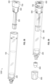
- FIG. 1 is a partially-exploded perspective view of a dosing dispenser including a housing, a base assembly, a drive screw, a traveler, an application tool, a cap, and a plunger according to aspects of the present invention.
- FIG. 2 is a perspective view of the traveler of FIG. 1 .
- FIG. 3 is a sectional view of the traveler of FIG. 2 .
- FIG. 4 is a perspective view of the drive screw of FIG. 1 .
- FIG. 5 is a perspective view of the plunger of FIG. 1 .
- FIG. 6 is an end view of the plunger of FIG. 5 .
- FIG. 7 is an end view of a plunger for a dosing dispenser according to an example of the present invention.
- FIG. 8 is a perspective view of a base support of the base assembly of FIG. 1 .
- FIG. 9 is a sectional view of the base support of FIG. 8 .
- FIG. 10 is an end view of the base support of FIG. 8 .
- FIG. 11 is an end view of a cam of the base assembly of FIG. 1 .
- FIG. 12 is an end view of the cam of FIG. 11 mounted on the base support of FIG. 8 .
- FIG. 13 is an exploded assembly view of the drive screw of FIG. 1 with the base support of FIG. 8 and the cam of FIG. 11 .
- FIG. 14 is a partially exploded assembly view of the drive screw, base support, and cam of FIG. 13 with a base of the base assembly of FIG. 1 .
- FIG. 15 is a perspective view of the drive screw, base support, cam, and base of FIG. 14 with the traveler of FIG. 1 .
- FIG. 16 is a sectional view of the drive screw, base support, cam, base, and traveler of FIG. 15 .
- FIG. 17 is a perspective view of the driver screw, base support, cam, base, and traveler of FIG. 15 with the housing and plunger of FIG. 1 .
- FIG. 18 is a partially exploded assembly view of the dispenser of FIG. 1 with the cap and application tool removed.
- FIG. 19 is a perspective view of a dispensing end of the housing.
- FIG. 20 is an enlarged sectional view of a portion of the dispenser of FIG. 1 including the plunger, housing, cap, and application tool.
- FIG. 21 is a perspective view of the dispenser of FIG. 1 .
- FIG. 22 is a perspective view of the dosing dispenser of FIG. 1 with the cap and application removed, a flowable composition in the housing, and the plunger and traveler in a first position.
- FIG. 23 is perspective view of the dosing dispenser of FIG. 22 with the plunger and traveler in a second position.
- FIG. 24 is a perspective view of the dosing dispenser of FIG. 23 with the application tool attached to the housing and the cap removed.
- FIG. 25 is sectional view of an application tool according to aspects of the present invention.
- FIG. 26 is sectional view of another application tool according to aspects of the present invention.
- FIG. 27 is sectional view of another application tool according to aspects of the present invention.
- FIG. 28 is a perspective view of a portion of a housing of a dispenser according to aspects of the present invention.
- FIG. 29 is an enlarged sectional view of the portion of the housing of FIG. 28 with a plunger.
- FIG. 30 is a perspective view of a portion of a dispenser including a cap and housing.
- FIG. 31 is a detail sectional view of the dispensing end of FIG. 28 with an application tool and cap.
- FIG. 32 is a sectional view of a portion of a dosing dispenser according to aspects of the present invention.
- FIG. 33 is an enlarged sectional view of a portion of the dosing dispenser of FIG. 32 .
- FIG. 34 is a perspective view a portion of a dosing dispenser with a lock tab in a disengaged configuration according to aspects of the present invention.
- FIG. 35 is a perspective view of the portion of the dosing dispenser of FIG. 34 with the lock tab in an engaged configuration.
- FIG. 36 is an exploded assembly view of a dosing dispenser according to aspects of the present invention.
- FIG. 37 is a sectional view of the dosing dispenser of FIG. 36 .
- FIG. 38 is an exploded assembly view of a dosing dispenser according to aspects of the present invention.
- FIG. 39 is a sectional view of the dosing dispenser of FIG. 38 .
- FIG. 40 an exploded assembly view of a dosing dispenser according to aspects of the present invention.
- FIG. 41 is a sectional view of the dosing dispenser of FIG. 40 .
- FIG. 42 is a partially exploded assembly view of a dosing dispenser according to aspects of the present invention.
- FIG. 43 is a sectional view of the dosing dispenser of FIG. 42 .
- FIG. 44 is a sectional view of a dosing dispenser according to aspects of the present invention.
- FIG. 45 is an exploded assembly view of a dosing dispenser according to aspects of the present invention.
- FIG. 46 is a perspective view of a portion of the dosing dispenser of FIG. 45 .
- FIG. 48 is an enlarged sectional view of a portion of the dosing dispenser of FIG. 45 including a housing and applicator tool.
- FIG. 49 is a perspective view of an applicator tool of the dosing dispenser of FIG. 45 .
- FIG. 50 is a perspective view of a portion of a dosing dispenser according to aspects of the present disclosure.
- FIG. 51 is a perspective sectional view of the portion of the dosing dispenser of FIG. 50 .
- FIG. 52 is a perspective view of a dosing dispenser according to aspects of the present invention.
- FIG. 53 is a sectional view of the dosing dispenser of FIG. 52 .
- FIG. 54 is a sectional view of a portion of the dosing dispenser of FIG. 52 engaged with a refilling device.
- FIG. 55 is a sectional view of a portion of the dosing dispenser of FIG. 52 .
- FIG. 56 is a perspective view of a traveler and drive screw of the dosing dispenser of FIG. 52 .
- FIG. 57 is a perspective view of the traveler, drive screw, base support, cam, and base of the dosing dispenser of FIG. 52 .
- FIG. 58 is a perspective view of the traveler, housing, plunger, drive screw, base support, cam, and base of the dosing dispenser of FIG. 52 .
- FIG. 59 is a perspective view of the traveler, housing, applicator tool, cap, plunger, drive screw, base support, cam, and base of the dosing dispenser of FIG. 52
- FIG. 1 illustrates example of a dispenser 10 that is configured to dispense a flowable composition.
- the flowable composition may include but is not limited to creams or semi-solid emulsions such as oil-in-water creams and water-in-oil creams, gels, sols, colloids, suspensions, solutions, liquids with positive viscosity such as syrups, or other suitable flowable compositions or medicaments.
- the dispenser 10 includes a housing 100 , a plunger 200 , a traveler 300 , a drive screw 400 , a base support 500 , a cam 600 , a base 700 , a cap 800 , and an applicator 900 .
- Some or all of the parts that comprise the dispenser 10 may be formed of materials including but not limited to polymer, plastic, composite, or other formable or moldable material.
- the housing 100 includes a body 102 having a first end 104 and a second end 106 .
- the body 102 defines a chamber 108 extending from the first end 104 to the second end 106 that is dimensioned and configured to store the flowable composition.
- the chamber 108 may have any cross-sections desired.
- a shape of the chamber 108 may be different from an exterior shape of the body 102 .
- the exterior shape of the body 102 may be oval, elliptical, triangular, square, hexagonal, pentagonal, circular, rectilinear, parabolic, hexagonal, other polygonal, irregular circular, or any other desired shape.
- the body 102 is an ergonomic shape.
- the first end 104 is a dispensing end of the housing 100 that includes a dispensing aperture 110 .
- the flowable composition may flow into or out of the chamber 108 through the dispensing aperture 110 .
- the first end 104 of the housing 100 also includes an applicator locking interface 112 (see, e.g., FIGS. 18 - 20 ).
- the locking interface 112 has a male Luer-style surface (see, e.g., FIGS. 28 - 31 ) or a female Luer-style surface (see, e.g., FIGS. 19 - 20 ).
- the applicator 900 may include a locking interface 906 that is complimentary to the locking interface 112 of the housing 100 .
- the locking interface 112 may also optionally include anti-rotation ribs 122 .
- the anti-rotation ribs 122 may provide an interface that resists casual rotation of the applicator 900 while the dispenser 10 is being used.
- the applicator 900 may optionally include complimentary anti-rotation grooves (not shown) that are configured to engage with the anti-rotation ribs 122 .
- the anti-rotation ribs 122 may be provided on the applicator 900 and the first end 104 may include the complimentary anti-rotation grooves.
- the first end 104 may also include threading 118 that is configured to engage with threading 806 of the cap 800 .
- the first end 104 may optionally comprise ribs 120 that are configured to engage with grooves 808 of the cap 800 to provide a stopping interface and align a shape of the cap 800 with a shape of the housing 100 .
- the grooves may be provided on the first end 104 and the ribs 120 may be provided on the cap 800 .
- the housing 100 may optionally include mounting slots 114 that are configured to engage the base support 500 in a snap-fit configuration.
- the mounting slots 114 are provided proximate to the second end 106 of the housing 100 , although they need not be. It will be appreciated that the disclosure of mounting slots 114 should not be considered limiting on the current disclosure as in various other examples, various other suitable mounting mechanisms may be utilized to assemble the base support 500 with the housing 100 .
- the plunger 200 is shaped to snugly fit within the chamber 108 without freely rotating within the chamber 108 .
- the chamber 108 may have some variation in size from top to bottom, with the second end typically being slightly smaller in cross-sectional area than the first end.
- the plunger 200 is configured with a flexible design that provides a fluid tight seal along the entire length of the chamber 108 and between variations among housing 100 sizes.
- the plungers 200 may be formed to have a greater degree of flexibility that allows the plunger 200 to bend or compress as needed to form a fluid tight seal inside smaller cross-section areas, and to flex or expand as needed to form a fluid tight seal inside larger cross-section areas.
- the plunger 200 includes a sealing member 214 that includes a flexible design configured to flexibly bend, compress, flex, and/or expand as needed to allow the plunger 200 to maintain a fluid tight seal within the chamber 108 .
- the plunger 200 includes two sealing members 214 , although it will be appreciated that any desired number of sealing members 214 , including zero sealing members 214 , may be used.
- the first end 204 of the plunger 200 may optionally include a crown 216 .
- the crown 216 may be provided to reduce the volume of residual flowable composition within the chamber 108 after use of the dispenser 10 .
- the crown 216 may partially extend into the dispensing aperture 110 before the chamber 108 is filled with the flowable composition, at various positions or dosages while or after the flowable composition is being dispensed, or both.
- the crown 216 may be provided to provide resistance to fold-over of the plunger 200 during filling of the chamber 108 with the flowable composition.
- the first end 204 of the plunger 200 may be flat, arcuate, angled, or have various other suitable shapes as desired.
- the first end 204 of the plunger 200 may also include ribs 218 .
- the ribs 218 may provide air passages between adjacent ribs 218 which may allow for pressure to build up across the first end 204 and reduce the initial force needed to start filling the chamber 108 with the flowable composition.
- second end 206 of the plunger 200 defines a cavity 208 having a cavity sidewall 210 and a cavity end wall 212 .
- the cavity 208 is dimensioned and configured to engage a plunger driver 314 of the traveler 300 such that the plunger 200 is movably positioned within the chamber 108 through the traveler 300 .
- a skirt of the plunger 200 or the portion of the body that extends from the cavity end wall 212 to the second end 206 , is provided to reduce fold-over or rotation of the plunger 200 during filling or dispensing of the flowable composition.
- the plunger 200 is configured to be positioned within the chamber 108 such that the first end 204 of the plunger 200 faces the first end 104 of the housing 100 and the second end 206 faces the second end 106 of the housing 100 .
- the traveler 300 includes a body 302 having a first end 304 and a second end 306 .
- the body 302 defines a chamber 308 that extends from the first end 304 to the second end 306 .
- the chamber 308 is shaped and dimensioned to accommodate the drive screw 400 , as described in detail below.
- the chamber 308 includes threading 310 that are configured to threadably engage the drive screw 400 .
- at least a portion of the chamber 308 such as a portion of the chamber 308 proximate to the second end 306 , includes the threading 310 .
- the threading 310 may be provided throughout the chamber 308 from the first end 304 to the second end 306 .
- the traveler 300 includes collars 312 at various positions on the body 302 .
- the collars 312 have a shape that is complimentary to the shape of the chamber 108 of the housing 100 such that rotation of the traveler 300 is resisted as the drive screw 400 moves the traveler 300 axially along the drive screw 400 within the chamber 108 .
- the number of collars 312 , the shape of the collars 312 , or the location of the collars 312 on the body 302 should not be considered limiting on the present disclosure.
- the traveler 300 includes two collars 312 A and 312 B. In this example, the collar 312 B is proximate to the second end 306 of the body 302 and the collar 312 A is proximate to the first end 304 .
- the traveler 300 includes a plunger driver 314 extending from proximate the first end 304 .
- the plunger driver 314 is shaped and dimensioned such that the plunger driver 314 may engage the plunger 200 within the plunger cavity 208 to movably position the plunger 200 within the chamber 108 .
- an end 316 of the plunger driver 314 is configured to engage the plunger 200 .
- the plunger driver 314 may have a cross-sectional profile shape that is complimentary to the shape of the plunger cavity 208 .
- the plunger driver 314 may optionally define a plunger drive chamber 318 that is in fluid communication with the chamber 308 .
- the end 316 of the plunger driver 314 may define an opening 320 , as illustrated in FIGS. 2 and 3 .
- the end 316 may be solid.
- the entire plunger driver 314 may be solid (i.e. the plunger driver 314 does not define a plunger drive chamber 318 ).
- the drive screw 400 includes a body 402 having a first end 404 , a second end 406 , and a support collar 410 between the first end 404 and the second end 406 .
- the body 402 includes threading 408 between the first end 404 and the support collar 410 that are configured to threadably engage the threading 310 of the traveler 300 such that rotation of the drive screw 400 axially moves the traveler 300 along the body 402 .
- at least a portion of the body 402 between support collar 410 and the second end 406 is a key 412 having a key profile that is configured to engage the base 700 such that rotation of the base 700 rotates the drive screw 400 , as described in detail below.
- the base support 500 includes a body 502 having a first end 504 and a second end 506 .
- the body 502 defines a central opening 508 extending through the body 502 from the first end 504 to the second end 506 that is dimensioned to accommodate the drive screw 400 .
- the body 502 has a mounting portion 510 proximate to the first end 504 and a supporting portion 512 proximate to the second end 506 .
- the base support 500 optionally defines an attachment groove 514 between the mounting portion 510 and the supporting portion 512 that is configured to engage the base 700 such that the base 700 is rotatably supported on the base support 500 , as described in detail below.
- the mounting portion 510 and the supporting portion 512 may have different cross-sectional profile shapes. In other cases, the mounting portion 510 and the supporting portion 512 may have similar cross-sectional profile shapes.
- the mounting portion 510 has a profile shape that is complimentary to the shape of the chamber 108 such that the mounting portion 510 may be inserted into the chamber 108 to couple the base support 500 with the housing 100 .
- the mounting portion 510 may include engagement projection 524 which are configured to engage the mounting slots 114 of the housing 100 in a snap-fit engagement. This engagement may also resist rotation of the base support 500 during use. It will be appreciated that in various other examples, various other suitable attachment mechanisms for engaging the base support 500 with the housing 100 may be used, such as screws, pins, bolts, clips, clasps, etc.
- the mounting portion 510 defines a mounting portion cavity 516 that is dimensioned and configured to accommodate the support collar 410 of the drive screw 400 .
- mounting projections 518 are provided within the mounting portion cavity 516 to retain the drive screw 400 axially relative to the base support 500 while allowing for rotation of the drive screw 400 relative to the base support 500 .
- the mounting projections 518 provide a snap-fit engagement with the support collar 410 of the drive screw 400 .
- other suitable mechanisms for retaining the drive screw 400 relative to the base support 500 while allowing for rotation of the drive screw 400 relative to the base support 500 may be used.
- the supporting portion 512 defines a supporting portion cavity 520 that is dimensioned and configured to accommodate the cam 600 . As illustrated in FIGS. 8 - 10 and 12 , the supporting portion 512 defines notches or slots 522 that are configured to engage arms 606 of the cam 600 , as described in detail below. The number of shape of the slots 522 should not be considered limiting on the current disclosure.
- the slots 522 define one or more home or “click” positions that are provided at predetermined intervals on the supporting portion 512 . The intervals of the slots 522 may correspond with a predefined amount of flowable composition is dispensed from the dispenser 10 upon rotation of the drive screw 400 between successive home positions, as described in detail below. In some cases, the slots 522 may be omitted and a sidewall of the supporting portion 512 may define projections and recesses that are configured to engage with the cam 600 in a similar manner (see FIGS. 46 - 51 ).
- the cam 600 includes a body 602 that defines a keyhole 604 .
- the keyhole 604 has a shape that is complimentary to the key 412 of the drive screw 400 such that the key 412 is insertable through the keyhole 604 , and rotation of the drive screw 400 rotates the cam 600 .
- the cam 600 includes at least one member 606 .
- the cam 600 includes three arms 606 as the at least one member. Some or all of the arms 606 may have the same engagement end 608 , or each arm 606 may have a different engagement end 608 , depending on the purpose of each arm 606 .
- the cam 600 may include the same number of arms 606 as the number of slots 522 of the base support 500 .
- At least one engagement end 608 includes a projection 610 and a trailing edge 612 .
- the trailing edge 612 is configured to engage the supporting portion 512 when the projection 610 is within one of the slots 522 to prevent rotation of the cam 600 in the direction of the trailing edge 612 .
- the trailing edge 612 may have various suitable profiles and geometries that provide an interface that resists rotation of the cam 600 in the direction of the trailing edge 612 when the projections 610 are within the slots 522 .
- the trailing edge 612 may have a profile that engages the supporting portion 512 such that the arms 606 of the cam 600 will break before allowing back rotation.
- At least one projection 610 also has a clicking profile 614 .
- one, some, or all of the projections 610 may have the clicking profile 614 .
- the clicking profile 614 is configured to sufficiently radially bend the engagement end 608 so as to emit an audible “click” when the engagement end 608 returns to an unbent stage after travelling over the supporting portion 512 and engages one of the slots 522 .
- the interaction between at least one of the projections 610 with the clicking profile 614 and at least one of the slots 522 may provide the audible “click” response, while the interaction between at least one of the projections 610 without the clicking profile 614 merely provide the anti-reverse rotation feature.
- the interaction between at least one of the projections 610 with the clicking profile 614 and at least one of the slots 522 may also provide tactile feedback.
- the interaction between at least one of the projections 610 without the clicking profile 614 (or with an additional clicking profile 614 ) may provide a back-up audible “click” to the audible “click” that is also emitted by the interaction between at least one of the projections 610 with the clicking profile 614 and at least one of the slots 522 .
- the auditory and/or tactile feedback from the interaction between at least one of the projections 610 with the clicking profile 614 and at least one of the slots 522 may alert the user that a predetermined amount of the flowable composition was dispensed.
- the base 700 includes a body 702 having a first end 704 and a second end 706 .
- the base 700 may have a profile shape that is similar to the profile shape of the base support 500 and/or the housing 100 , although it need not. In various other cases, the base 700 may have any desired profile shape.
- the base 700 defines a keyhole 708 that is dimensioned to accommodate and receive the key 412 of the drive screw 400 .
- the base 700 defines a base cavity 710 that is configured to accommodate the cam 600 and the supporting portion 512 .
- the base 700 includes projections 712 which are configured to engage the attachment groove 514 such that the base 700 is retained on the base support 500 while being rotatable relative to the base support 500 . In various other examples, various other mounting mechanisms may be utilized.
- the base 700 When assembled on the base support 500 , the base 700 retains the cam 600 on the drive screw 400 between the base support 500 and the base 700 .
- the base 700 may provide visual feedback to the user to indicate when at least one of the projections 610 with the clicking profile 614 is engaged with at least one of the slots 522 .
- the base 700 may provide visual feedback that the at least one projection 610 is not engaged with the slot 522 when the profile of the base 700 is misaligned with the profile of the base support 500 and/or the housing 100 .
- the base 700 may provide visual feedback that the at least one projection 610 is engaged within the slot 522 when the profile of the base 700 is aligned with the profile of the base support 500 and/or the housing 100 .
- Various other visual feedback may be provided by the base 700 when compared to the base support 500 and/or the housing 100 .
- FIGS. 13 - 18 illustrate another non-limiting example of steps for assembling the dispenser 10 .
- the drive screw 400 is inserted through the central opening 508 of the base support 500 and the support collar 410 of the drive screw 400 is snap-fit into the mounting portion cavity 516 of the base support 500 .
- the keyhole 604 of the cam 600 is aligned with the key 412 of the drive screw 400 and the cam 600 is slid onto the drive screw 400 .
- the base 700 is rotatably mounted on the base support 500 such that the cam 600 is captured on the drive screw 400 between the base 700 and the base support 500 .
- the traveler 300 is threaded onto the drive screw 400 and run along the drive screw 400 such that the second end 306 of the traveler 300 is relatively close to the support collar 410 of the drive screw 400 . In some cases, the second end 306 may abut the support collar 410 , although it need not.
- the plunger 200 is inserted into the chamber 108 of the housing 100 such that the first end 204 of the plunger 200 faces the first end 104 of the housing 100 and the second end 206 of the plunger 200 faces the second end 106 of the housing 100 .
- the plunger 200 is inserted such that the first end 204 abuts the first end 104 of the housing 100 within the chamber 108 .
- a portion of the crown 216 may be inserted into the dispensing aperture 110 of the housing 100 .
- the base support 500 which indirectly supports the traveler 300 , the drive screw 400 , the cam 600 , and the base 700 , is coupled to the housing 100 .
- the base support 500 is coupled to the housing 100 by inserting the mounting portion 510 of the base support 500 within the chamber 108 and snap-fitting the engagement projections 524 of the mounting portion 510 with the mounting slots 114 of the housing 100 .
- various other mounting mechanisms and configurations may be used to mount the base support 500 , traveler 300 , drive screw 400 , cam 600 , and base 700 to the housing 100 .
- the desired applicator 900 is attached to the first end 104 of the housing 100 .
- the cap 800 is removably attached to the housing 100 at the first end 104 .
- the housing locking interface 906 is complimentary to the applicator locking interface 112 .
- the locking interface 906 may be a male Luer-style interface or a female Luer-style interface.
- the locking interface 906 (or the locking interface 112 ) may be tamper-proof such that a user may not remove the applicator 900 after a doctor or other person initially fills the dispenser with the flowable composition and attaches the applicator 900 to the housing 100 .
- the dispensing channel 908 is in fluid communication with the chamber 108 and dispensing aperture 110 of the housing 100 .
- the traveler 300 engages the plunger 200 .
- the plunger driver 314 engages the plunger 200 within the plunger cavity 208 .
- the end 316 of the plunger driver 314 engages the cavity end wall 212 of the plunger 200 .
- the applicator 900 is attached to the first end 104 of the housing 100 .
- FIGS. 28 - 31 illustrate an example of the dispenser 10 where the locking interface 112 of the housing 100 is a male Luer-style surface and the locking interface 906 of the applicator 900 is a female Luer-style surface.
- the housing 100 includes ribs 128 .
- the ribs 128 may provide a stopping interface with the locking interface 906 , somewhat similar to the ribs 120 .
- the locking interface 112 may extend a certain distance above the threads 118 , which may help reduce the amount of flowable composition that may get caught in the threads 118 during use.
- the locking tab 116 may engage the locking groove 714 as desired by the user.
- the locking tab 116 engaged with the locking groove 714 may prevent inadvertent rotation of the base 700 .
- the locking tab 116 may also be provided for child-resistant operation of the dispenser 10 .
- FIGS. 36 and 37 illustrate an example of a dispenser 40 that is substantially similar to the dispenser 10 except that the traveler 300 and base support 500 are modified.
- the base support 500 includes two halves 526 A-AB that are coupled to each other through snap-fitting or various other suitable attachment mechanisms.
- Each half 526 A-B includes a locking groove 528 that is configured to retain the support collar 410 of the drive screw 400 when the halves 526 A-B are assembled.
- the mounting portion 510 of each half includes a guide 530 .
- the guides 530 are configured to engage projections 322 provided along the body 302 of the traveler 300 to prevent rotation of the traveler 300 as the traveler 300 is axially positioned along the drive screw 400 .
- the cross-sectional shape of the assembled base support 500 is different that the cross sectional shape of the housing 100 .
- the base support 500 and housing 100 of the dispenser 40 have a circular shape, although they need not.
- the base support 500 is coupled to the housing 100 in a snap-fit configuration such that a portion of the base support 500 overlaps a portion of the housing 100 .
- the second end 106 of the housing 100 is within the mounting portion cavity 516 of the base support 500 .
- the base 700 includes a base projection 716 that is insertable into the supporting portion cavity 520 of the base support such that the base 700 is rotatably supported by the base support 500 .
- Threads 426 are provided along the outer surface of the body 416 and are configured to engage with the threads 310 of the traveler 300 .
- a first stopper 428 may be provided on the outer surface proximate to the first end 418 to prevent disengagement of the traveler 300 from the driving element 414 .
- a second stopper 430 may be provided within the central channel 422 proximate to the second end 420 to prevent disengagement of the driving element 414 from the drive screw 400 .
- this screw within a screw arrangement of the traveler 300 , driving element 414 , and drive screw 400 may be used to reduce an overall length of the dispenser 50 .
- the dispenser 50 includes an end wall 115 defining an aperture 117 , and a portion of the base 700 is insertable through the aperture 117 in the end wall 115 .
- the traveler 300 also includes a traveler cover 324 .
- the traveler cover 324 includes at least one slot 326 that may be used as a guide for projections 328 of the traveler 300 .
- the traveler cover 324 may also include projections 330 that are configured to engage with the housing 100 or the base support 500 to reduce or restrict rotation of the traveler 300 and traveler cover 324 during use.
- FIGS. 40 and 41 illustrate an example of a dispenser 60 that is substantially similar to the dispenser 40 except that the halves 526 A-B define the attachment groove 514 .
- the base 700 attaches to the base support 500 by engaging the attachment groove 514 such that at least a portion of the base support 500 is within the base cavity 710 .
- the dispenser 60 may function as a syringe when the halves 526 A-B are omitted.
- FIGS. 42 and 43 illustrate an example of a dispenser 70 that is similar to the dispenser 60 except that the base support 500 is a unitary piece rather than having the two halves 526 A-B that are detachably connected.
- FIG. 44 illustrates another example of a dispenser 80 in which the traveler 300 and plunger 200 are integrally formed as a single component 201 .
- the housing 100 , base support 500 and/or base 700 may be similar to that of any of the dispensers described previously.
- FIGS. 45 - 49 illustrate an example of a dispenser 90 that is substantially similar to the dispenser 10 except that the locking interface 112 of the housing 100 is a female Luer-style surface and the locking interface 906 of the applicator 900 is a male Luer-style surface.
- the female Luer-style locking interface 112 may allow for direct attachment of the dispenser 90 to various Luer-lock syringes on the market for filling without an adapter.
- the housing locking interface 906 includes an engagement collar 918 that is configured to snap-fit onto the housing 100 within the chamber 108 (see, e.g., FIG. 47 ).
- the snap-fit engagement between the applicator 900 and the housing 100 through the engagement collar 918 may provide a more consistent and/or tight gap between the housing 100 and the applicator 900 .
- the snap-fit engagement through the engagement collar 918 may limit or prevent removal of the applicator 900 from the housing 100 .
- the crown 216 of the plunger 200 optionally includes an applicator recess 220 that is dimensioned to accommodate the engagement collar 918 when the plunger 200 abuts the first end 104 of the housing 100 within the chamber 108 .
- the crown 216 may or may not be insertable within the dispensing channel 908 .
- the applicator recess 220 is omitted from the plunger 200 . The size and shape of the applicator recess 220 should not be considered limiting on the current disclosure.
- FIGS. 50 and 51 illustrate an example of a dispenser 1100 that is substantially similar to the dispenser 10 except that the locking interface 112 of the housing 100 is a female Luer-style surface that further includes internal cored sections 1102 and external cored sections 1104 .
- the cored sections 1102 and 1104 may reduce thick sections of the housing 100 that may otherwise be present, and therefore reduce the weight of the dispenser 1100 .
- the cored sections 1102 and 1104 alternate around a perimeter of the dispensing aperture 110 , although they need not.
- the internal cored sections 1102 are offset from the external cored sections 1104 , which may allow for thickness reduction of the housing 100 while maintaining the chamber 108 .
- FIGS. 52 - 59 illustrate an example of a dispenser 1200 that is substantially similar to the dispenser 10 except that the crown 216 of the plunger 200 is modified and the housing 100 defines an intermediate chamber 124 between the chamber 108 and the dispensing aperture 110 .
- the crown 216 may partially extend into the dispensing aperture 110 and/or the intermediate chamber 124 before the chamber 108 is filled with the flowable composition, at various positions or dosages while or after the flowable composition is being dispensed, or both.
- the crown 216 optionally may engage a refilling device 1202 (e.g., a filling syringe) during filling of the dispenser 1200 with the flowable composition, although it need not.
- a refilling device 1202 e.g., a filling syringe
- air gaps 1204 are defined in the intermediate chamber 124 when the plunger 200 is in the intermediate chamber 124 . In other examples, the air gaps 1204 may be omitted.
- the housing 100 also includes a locking tab 126 or other similar mechanism in or proximate to the dispensing aperture 110 .
- the locking tab 126 may facilitate engagement and securing the applicator 900 on the housing 100 (and optionally within the dispensing aperture 110 .
- FIGS. 56 - 59 illustrate a non-limiting example of steps for assembly the dispenser 1200 .
- the traveler 300 in a first step, is run all the way up the drive screw 400 (see FIG. 56 ).
- the traveler 300 is run up the drive screw 400 such that the traveler abuts the support collar 410 .
- the base support 500 , cam 600 , and base 700 are assembled and secured onto the drive screw 400 (see FIG. 57 ).
- the plunger 200 is positioned within the chamber 108 of the housing 100 .
- the plunger 200 is inserted such that the plunger is at least partially positioned within the intermediate chamber 124 (see FIG. 58 ).
- the assembled traveler 300 , drive screw 400 , base support 500 , cam 600 , and base 700 are assembled with the housing 100 such that the traveler 300 is movable within the chamber 108 (see FIG. 59 ).
- the chamber 108 is filled with the appropriate measured amount of flowable composition.
- the base 700 is turned so that the drive screw 400 turns and advances the plunger 200 and flowable composition toward the first end 104 of the housing 100 .
- the applicator 900 is then snapped onto the first end 104 of housing 100 .
- the base 700 is turned and the plunger 200 is advanced until there is essentially no air inside the chamber 108 between the flowable composition and the applicator 900 .
- the cap 800 is placed on the applicator 900 and the dispenser 10 is ready for use.
- the user removes the cap 800 and turns the base 700 the appropriate amount of clicks (typically as directed on the instructions given to the user by the dispensing physician or pharmacy).
- the arms 606 of the cam 600 flex and move over the cam 600 as described above, and/or at least projection 610 moves toward at least one of the slots 522 .
- the projection 610 passes over and into the slot 522 , at least one audible “click” is heard when the base 700 reaches a home or “click” position.
- the user may sense a vibration when the base 700 reaches a home or “click” position.
- a predetermined amount of flowable composition 1000 is forced by the rising plunger 200 to be dispensed through the applicator 900 .
- the dispensed flowable composition 1000 may form a bead or pool over the central area of the applicator surface 904 of the applicator 900 .
- the user applies the flowable composition 1000 to the skin by rubbing the applicator 900 on the skin.
- the flowable composition 1000 at least partially spreads out over the applicator surface 904 and is rubbed into the skin.
- the tactile and audible click heard as the base 700 is rotated provides feedback as to how much flowable composition 1000 is dispensed.
- the prescription might be for 1 cc of flowable composition 1000 per dose to be applied to the skin. If each click is 0.25 cc, for example, then the prescription might instruct the user to turn the base 700 to hear four clicks so as to dispense 1 cc of flowable composition 1000 .
- the design of the present invention substantially prevents reverse rotation of the base 700 with respect to the housing 100 so that flowable composition 1000 is not inadvertently sucked back into the dispenser 10 , which may reduce the effective dosage dispensed and may contaminate the flowable composition 1000 in the chamber 108 .
- the click also provides positive feedback when the right amount of flowable composition 1000 has been dispensed per turn.
- the amount of flowable composition 1000 dispensed per click may be adjusted or varied by changing the distance or amount of rotation of the base 700 between clicks.
- changing the amount of rotation of the base 700 between clicks may include changing the size, number, or shape of the slots 522 of the base support 500 , changing the threads 408 on the drive screw 400 , and/or changing the size, number, or shape of the arms 606 of the cam 600 , among others.
- the dispenser 10 of the present invention may optionally include a vibration mechanism whereby the dispenser 10 and, in particular, the applicator 900 area vibrates when activated so as to improve transfer of the flowable composition 1000 to the skin.
- the vibration mechanism may be one of several possible mechanisms known to those skilled in the art.
- the dispenser of the present invention may also include an indicator mechanism either to show the approximate number of remaining doses or to show when the chamber 108 is near empty, both so that the user can have advance awareness that a refill may be needed.
- the indicator may be a visual indicator, such as ruler with a set of marks along the side of the housing 100 , with each mark being correlated to a particular quantity of flowable composition 1000 remaining in the dispenser 10 .
- the housing 100 or at least a portion thereof (such as an elongated window extending from near the first end 104 to near the second end 106 ) may be clear or translucent.
- FIG. 18 illustrates the dispenser with a visual indicator 101 wherein the visual indicator 101 includes at least one mark.
- the visual indicator 101 may provide a visual indication for home or “click” positions.
- the visual indicator 101 may be through a shape of components, such as the shape of the base 700 and the shape of the body 102 .
- the dispenser 10 provides a visual indication of the home or “click” positions when the shape or outline of the base 700 aligns with the shape or outline of the body 102 as the base 700 is rotated relative to the body 102 .
- both the body 102 and the base 700 may be triangular shaped, and a home or “click” position is visually indicated when the corners of the base 700 align with the corners of the body 102 .
- Various other visual indicators may be provided for providing visual indication of the home or “click positions,” including, but not limited to, aligning components, marks, dots, stripes, colors, etc.
- the volume is modular so that different housings 100 having chambers 108 with different volumes may be interchanged while using the same plunger 200 , base support 500 , cam 600 , base 700 , cap 800 , and applicator 900 .
- the same traveler 300 and drive screw 400 may be used with the different sized housing 100 , or the size of the traveler 300 and drive screw 400 may be adjusted depending on the size of the chamber 108 .
- a dosing dispenser including: a housing having a first end and a second end, the housing defining a chamber extending from the first end to the second end, the first end of the housing including a dispensing channel in fluid communication with the chamber; a plunger including a first end and a second end, the plunger positionable within the chamber with the first end proximate to the first end of the housing and the second end proximate to the second end of the housing, the second end of the plunger defining a plunger cavity, the plunger defining a filling portion of the chamber between the first end of the housing and the first end of the plunger; and a traveler including a first end and a second end, the traveler positionable within the chamber, the first end including a plunger driver configured to selectively engage the plunger within the plunger cavity and movably position the plunger within the chamber.
- the dosing dispenser of any of the preceding or subsequent example combinations further including a base assembly coupled to the second end of the housing, the base assembly including a base and configured to movably position the traveler within the chamber through rotation of the base.
- the base assembly further includes: a drive screw threadably engaged with the traveler and coupled to the base such that rotation of the base rotates the drive screw and axially moves the traveler within the chamber; a base support rotatably supporting the drive screw and the base, the base support including a mounting portion and a supporting portion, the supporting portion including at least one notch; and a cam mounted on the drive screw and including at least one extension configured to engage the at least one notch as the cam is rotated through the drive screw.
- EC 4 The dosing dispenser of any of the preceding or subsequent example combinations, wherein the drive screw includes a first end, a second end, and a support collar between the first end and the second end, wherein the drive screw includes external threads between the first end and the support collar configured to threadably engage the traveler, and wherein the base support axially retains the drive screw relative to the base support through engagement of the base support with the support collar of the drive screw.
- EC 5 The dosing dispenser of any of the preceding or subsequent example combinations, wherein the traveler is movable between an engaged position and a disengaged position relative to the plunger; wherein in the disengaged position, the traveler is spaced apart from the plunger, and wherein in the engaged position, the plunger driver of the traveler abuts the plunger within the plunger cavity.
- EC 6 The dosing dispenser of any of the preceding or subsequent example combinations, wherein a cross-sectional shape of the plunger is substantially similar to a cross-sectional shape of the chamber such that the plunger forms a fluid tight seal with the housing within the chamber as the plunger is movably positioned within the chamber.
- EC 7 The dosing dispenser of any of the preceding or subsequent example combinations, wherein the first end of the plunger includes a crown, and wherein at least a portion of the crown is positionable within the dispensing channel of the housing when a volume of the filling portion of the chamber is at a minimum.
- a dosing dispenser including: a housing having a first end and a second end, the housing defining a chamber extending from the first end to the second end, the first end of the housing including a dispensing channel in fluid communication with the chamber; a plunger including a first end and a second end, the plunger positionable within the chamber with the first end proximate to the first end of the housing and the second end proximate to the second end of the housing, the second end of the plunger defining a plunger cavity, the plunger defining a filling portion of the chamber between the first end of the housing and the first end of the plunger; and a base assembly coupled to the second end of the housing, the base assembly including a base and configured to movably position the plunger within the chamber through rotation of the base.
- EC 9 The dosing dispenser of any of the preceding or subsequent example combinations, further including a traveler within the chamber and coupled to the base assembly, wherein the traveler includes a plunger driver configured to selectively engage the plunger within the plunger cavity, and wherein the traveler is configured to axially move within the chamber through rotation of the base of the base assembly.
- the base assembly further includes a drive screw, wherein the base is coupled to the drive screw such that rotation of the base rotates the drive screw, and wherein the drive screw is threadably engaged with the traveler such that rotation of the drive screw axially moves the traveler.
- EC 11 The dosing dispenser of any of the preceding or subsequent example combinations, wherein the traveler is movable between a disengaged position and an engaged position relative to the plunger, wherein in the disengaged position, the traveler is spaced apart from the plunger within the chamber, and wherein in the engaged position, the plunger driver abuts the plunger within the plunger cavity.
- the base assembly further includes: a base support including a mounting portion and a supporting portion, wherein the mounting portion is coupled to the second end of the housing, wherein the supporting portion defines a supporting portion cavity and at least one notch, and wherein the base support rotatably supports the base relative to the housing; and a cam including a body and at least one arm, wherein the cam is retained within the supporting portion cavity and rotatable relative to the base support, and wherein the cam is configured to provide auditory feedback upon engagement of the at least one arm with the at least one notch as the cam is rotated.
- EC 13 The dosing dispenser of any of the preceding or subsequent example combinations, wherein a cross-sectional shape of the mounting portion of the base support is different from a cross-sectional shape of the supporting portion of the base support, and wherein a cross-sectional shape of the housing is substantially similar to a cross-sectional shape of the base.
- EC 14 The dosing dispenser of any of the preceding or subsequent example combinations, wherein a cross-sectional shape of the plunger is substantially similar to a cross-sectional shape of the chamber such that the plunger forms a fluid tight seal with the housing within the chamber as the plunger is movably positioned within the chamber.
- a dosing dispenser including: a housing having a first end and a second end, the housing defining a chamber extending from the first end to the second end, the first end of the housing including a dispensing channel in fluid communication with the chamber; a plunger including a first end and a second end, the plunger positionable within the chamber with the first end proximate to the first end of the housing and the second end proximate to the second end of the housing, the second end of the plunger defining a plunger cavity, the plunger defining a filling portion of the chamber between the first end of the housing and the first end of the plunger; and a traveler including a plunger driver, the traveler configured to movably position the plunger within the chamber, the traveler movable between a disengaged position and an engaged position relative to the plunger, wherein in the disengaged position, the traveler is spaced apart from the plunger within the chamber, and wherein in the engaged position, the plunger driver abuts the plunger within
- EC 16 The dosing dispenser of any of the preceding or subsequent example combinations, wherein in the engaged position, the traveler and plunger are movable within the chamber between a filled position and a dispensed position, wherein in the filled position, the first end of the plunger is spaced apart from the first end of the housing and volume of the filling portion of the chamber is at a maximum, and wherein in the dispensed position, the first end of the plunger abuts the first end of the housing and the volume of the filling portion of the chamber is at a minimum.
- EC 18 The dosing dispenser of any of the preceding or subsequent example combinations, wherein the traveler defines a traveler chamber extending from the first end to the second end, wherein at least a portion of the traveler chamber includes threading, and wherein the dosing dispenser further includes a drive screw threadably engaged with the threading of the traveler and configured to movably position the traveler within the chamber.
- the dosing dispenser of any of the preceding or subsequent example combinations further including a base assembly coupled to the second end of the housing, the base assembly including a base and configured to movably position the traveler within the chamber through rotation of the base, wherein the base assembly further includes: a drive screw threadably engaged with the traveler and coupled to the base such that rotation of the base rotates the drive screw and axially moves the traveler within the chamber; a base support rotatably supporting the drive screw and the base, the base support including a mounting portion and a supporting portion, the supporting portion including at least one notch; a cam mounted on the drive screw and including at least one extension configured to engage the at least one notch as the cam is rotated through the drive screw.
- EC 20 The dosing dispenser of any of the preceding or subsequent example combinations, wherein the drive screw includes a first end, a second end, and a support collar between the first end and the second end, wherein the drive screw includes external threads between the first end and the support collar configured to threadably engage the traveler, wherein the drive screw includes a key between the support collar and the second end, and wherein the base and cam each define a keyhole dimensioned to accommodate the key.
- a dosing dispenser comprising: a housing defining a chamber; a traveler within the chamber; and a plunger within the chamber, wherein the traveler is movable along an axis between an engaged position and a disengaged position relative to the plunger, and wherein the traveler is spaced apart from the plunger in the disengaged position.
- EC 22 The dosing dispenser of any of the preceding or subsequent example combinations, wherein the plunger comprises a first end and a second end, wherein the second end of the plunger defines a plunger cavity, and wherein the plunger defines a filling portion of the chamber between the first end of the housing and the first end of the plunger.
- EC 25 The dosing dispenser of any of the preceding or subsequent example combinations, further comprising a base assembly coupled to the housing, the base assembly comprising a base and configured to movably position the traveler within the chamber through rotation of the base.
- EC 26 The dosing dispenser of any of the preceding or subsequent example combinations, wherein in the disengaged position, the traveler is spaced apart from the plunger, and wherein in the engaged position, a plunger driver of the traveler abuts the plunger within a plunger cavity of the plunger.
- EC 28 The dosing dispenser of any of the preceding or subsequent example combinations, wherein the housing further comprises an intermediate chamber between the chamber and the dispensing channel, and wherein at least a portion of the crown is positionable within the intermediate chamber when the volume of the filling portion of the chamber is at the minimum.
- a dosing dispenser comprising: a housing defining a chamber; a traveler positionable within the chamber; and a plunger positionable within the chamber, wherein the traveler is independently positionable along an axis relative to the plunger in at least one direction within the chamber.
- EC 30 The dosing dispenser of any of the preceding or subsequent example combinations, wherein the chamber comprises a first end and a second end, wherein the housing further comprises a dispensing channel in fluid communication with the chamber at the first end, and wherein the at least one direction is away from the first end.
- EC 31 The dosing dispenser of any of the preceding or subsequent example combinations, wherein the housing further comprises a dispensing channel in fluid communication with the chamber, and wherein the at least one direction is away from the dispensing channel.
- EC 32 The dosing dispenser of any of the preceding or subsequent example combinations, wherein the traveler is configured to abut and selectively position the plunger in the a direction opposite the at least one direction.
- EC 33 The dosing dispenser of any of the preceding or subsequent example combinations, further comprising a base assembly configured to movably position the traveler within the chamber.
- the base assembly comprises: a base; a drive screw threadably engaged with the traveler and coupled to the base such that rotation of the base rotates the drive screw and axially moves the traveler within the chamber; a base support rotatably supporting the drive screw and the base, the base support comprising a mounting portion and a supporting portion, the supporting portion comprising at least one notch; and a cam mounted on the drive screw and comprising at least one extension configured to engage the at least one notch as the cam is rotated through the drive screw.
- EC 35 The dosing dispenser of any of the preceding or subsequent example combinations, wherein a cross-sectional shape of the plunger is substantially similar to a cross-sectional shape of the chamber such that the plunger forms a fluid tight seal with the housing within the chamber as the plunger is movably positioned within the chamber.
- a method of dispensing a flowable composition with a dosing dispenser comprising: positioning a plunger within a chamber defined by a housing of the dosing dispenser; positioning a traveler within the chamber such that the traveler is spaced apart from the plunger; and loading the flowable composition within the chamber.
- EC 38 The method of any of the preceding or subsequent example combinations, wherein the plunger comprises a crown, and wherein positioning the plunger within the chamber comprises positioning at least a portion of the crown within the dispensing channel.
- loading the flowable composition comprises loading a predetermined volume of the flowable composition within the chamber between a dispensing end of the housing and a first end of the plunger facing the dispensing end, and wherein the method further comprises: advancing the traveler within the chamber such that the traveler abuts a second end of the plunger opposite the first end after the predetermined volume is loaded; and dispensing the flowable composition from the dispensing end of the housing by advancing the traveler towards the dispensing end.
- EC 40 The method of any of the preceding or subsequent example combinations, further comprising: positioning the traveler within the chamber such that the traveler abuts the plunger after the flowable composition is loaded; and advancing the traveler within the chamber such that the traveler movably positions the plunger within the chamber and dispenses the flowable composition from the housing.
- a method of dispensing a flowable composition with a dosing dispenser comprising: positioning a plunger within a chamber defined by a housing of the dosing dispenser; positioning a traveler within the chamber such that the traveler is spaced apart from the plunger; and loading the flowable composition within the chamber, wherein loading the flowable composition within the chamber abuts the flowable composition against the plunger and moves the plunger within the chamber independently from the traveler.
Abstract
Description
Claims (23)
Priority Applications (2)
| Application Number | Priority Date | Filing Date | Title |
|---|---|---|---|
| US17/171,425 US11685590B2 (en) | 2016-12-27 | 2021-02-09 | Dosing dispenser system |
| US18/069,826 US11731827B1 (en) | 2016-12-27 | 2022-12-21 | Dosing dispenser system |
Applications Claiming Priority (5)
| Application Number | Priority Date | Filing Date | Title |
|---|---|---|---|
| US201662439280P | 2016-12-27 | 2016-12-27 | |
| US15/847,167 US10435226B2 (en) | 2016-12-27 | 2017-12-19 | Dosing dispenser system |
| US16/545,956 US10919685B2 (en) | 2016-12-27 | 2019-08-20 | Dosing dispenser system |
| US16/807,154 US10947027B2 (en) | 2016-12-27 | 2020-03-02 | Dosing dispenser system |
| US17/171,425 US11685590B2 (en) | 2016-12-27 | 2021-02-09 | Dosing dispenser system |
Related Parent Applications (1)
| Application Number | Title | Priority Date | Filing Date |
|---|---|---|---|
| US16/807,154 Continuation US10947027B2 (en) | 2016-12-27 | 2020-03-02 | Dosing dispenser system |
Related Child Applications (1)
| Application Number | Title | Priority Date | Filing Date |
|---|---|---|---|
| US18/069,826 Continuation US11731827B1 (en) | 2016-12-27 | 2022-12-21 | Dosing dispenser system |
Publications (2)
| Publication Number | Publication Date |
|---|---|
| US20210163212A1 US20210163212A1 (en) | 2021-06-03 |
| US11685590B2 true US11685590B2 (en) | 2023-06-27 |
Family
ID=62625465
Family Applications (5)
| Application Number | Title | Priority Date | Filing Date |
|---|---|---|---|
| US15/847,167 Active US10435226B2 (en) | 2016-12-27 | 2017-12-19 | Dosing dispenser system |
| US16/545,956 Active US10919685B2 (en) | 2016-12-27 | 2019-08-20 | Dosing dispenser system |
| US16/807,154 Active US10947027B2 (en) | 2016-12-27 | 2020-03-02 | Dosing dispenser system |
| US17/171,425 Active US11685590B2 (en) | 2016-12-27 | 2021-02-09 | Dosing dispenser system |
| US18/069,826 Active US11731827B1 (en) | 2016-12-27 | 2022-12-21 | Dosing dispenser system |
Family Applications Before (3)
| Application Number | Title | Priority Date | Filing Date |
|---|---|---|---|
| US15/847,167 Active US10435226B2 (en) | 2016-12-27 | 2017-12-19 | Dosing dispenser system |
| US16/545,956 Active US10919685B2 (en) | 2016-12-27 | 2019-08-20 | Dosing dispenser system |
| US16/807,154 Active US10947027B2 (en) | 2016-12-27 | 2020-03-02 | Dosing dispenser system |
Family Applications After (1)
| Application Number | Title | Priority Date | Filing Date |
|---|---|---|---|
| US18/069,826 Active US11731827B1 (en) | 2016-12-27 | 2022-12-21 | Dosing dispenser system |
Country Status (1)
| Country | Link |
|---|---|
| US (5) | US10435226B2 (en) |
Families Citing this family (6)
| Publication number | Priority date | Publication date | Assignee | Title |
|---|---|---|---|---|
| US10435226B2 (en) | 2016-12-27 | 2019-10-08 | Doselogix, Llc | Dosing dispenser system |
| US11040181B2 (en) | 2017-01-04 | 2021-06-22 | Reflex Medical Corp. | Metered dose topical applicator |
| CN110799059B (en) * | 2017-06-27 | 2022-07-15 | 埃姆弗西斯进出口及分销有限公司 | Dispensing container |
| WO2019157286A1 (en) * | 2018-02-09 | 2019-08-15 | Sonoco Development, Inc. | Twist action portion control sauce dispenser |
| CH715144A1 (en) * | 2018-07-02 | 2020-01-15 | Edelweiss Dr Ag | Extrusion device and composite distribution system. |
| US10682663B2 (en) * | 2018-10-31 | 2020-06-16 | The Boeing Company | Methods for dispensing flowable materials |
Citations (173)
| Publication number | Priority date | Publication date | Assignee | Title |
|---|---|---|---|---|
| US738531A (en) * | 1902-05-14 | 1903-09-08 | William B Dolsen | Hermetic gaseous-liquid-compress cask. |
| US800573A (en) * | 1904-12-28 | 1905-09-26 | Edgar J Hazelton | Dauber for shoe-dressing. |
| US835446A (en) | 1906-02-28 | 1906-11-06 | John E Lesueur | Non-refillable bottle. |
| US1342450A (en) | 1919-01-30 | 1920-06-08 | Quality Brands Company | Glazing-machine |
| US1701663A (en) | 1927-12-13 | 1929-02-12 | Will A Clark | Dispensing container for paste shoe polish |
| US2052296A (en) * | 1935-10-15 | 1936-08-25 | Huntley James | Dispenser for plastic toilet preparations |
| US2118346A (en) * | 1938-02-12 | 1938-05-24 | Edward J Goeritz | Dispensing container |
| US2172517A (en) * | 1939-09-12 | Toilet cream dispenser | ||
| GB666082A (en) | 1949-04-27 | 1952-02-06 | Robert Brighten Salisbury | Improvements in or relating to toothbrushes |
| US2754822A (en) | 1954-02-15 | 1956-07-17 | Emelock Melvin | Instrument for the administration of suppositories |
| US2812763A (en) | 1956-07-17 | 1957-11-12 | Becton Dickinson Co | Syringe assembly |
| US2869546A (en) | 1957-11-12 | 1959-01-20 | Edward B Cantor | Vaginal applicator |
| US2917765A (en) | 1957-10-18 | 1959-12-22 | Shulton Inc | Dispensing container |
| US3007611A (en) | 1959-07-09 | 1961-11-07 | Paul C Coolidge | Metering dispenser for flowable materials |
| US3026872A (en) | 1952-05-17 | 1962-03-27 | American Cyanamid Co | Hypodermic syringe |
| US3054503A (en) | 1961-04-06 | 1962-09-18 | Sparks Corp | Push-out-blister package |
| US3156387A (en) | 1961-04-04 | 1964-11-10 | Julian L Harwood | Combined package and dispensing unit for pasty materials |
| US3220413A (en) | 1961-04-03 | 1965-11-30 | Sunnen Joseph | Applicator |
| US3227161A (en) | 1963-03-04 | 1966-01-04 | Lorenzo Joseph P De | Syringe |
| US3253592A (en) | 1962-06-08 | 1966-05-31 | Baxter Don Inc | Plastic syringe |
| US3306252A (en) | 1963-12-03 | 1967-02-28 | Johnson & Johnson | Shielded aerosol medicament dispenser |
| US3333740A (en) | 1965-10-28 | 1967-08-01 | Charles D Waller | Screw actuated dispenser |
| US3424158A (en) | 1966-06-21 | 1969-01-28 | Jules Silver | Combination plastic mold,suppository package,dispenser and method for providing and using the same |
| US3540448A (en) | 1968-01-17 | 1970-11-17 | Joseph Sunnen | Rechargeable applicator for dispensing substances in a foam condition |
| US3581399A (en) | 1969-08-08 | 1971-06-01 | Centrix Inc | Composite resin filling syringe and technique |
| US3616970A (en) | 1968-02-13 | 1971-11-02 | Baumann Ag | Container construction for dispensing a pasty mass or the like |
| US3656480A (en) | 1969-06-17 | 1972-04-18 | Leveen Harry H | Syringe |
| US3656482A (en) | 1970-01-19 | 1972-04-18 | Joseph Sunnen | Applicator for dispensing substances |
| US3659749A (en) | 1970-04-28 | 1972-05-02 | Boris Schwartz | Intermixing syringe |
| US3802023A (en) | 1971-12-06 | 1974-04-09 | Spatz Corp | Brush |
| US3873008A (en) | 1974-01-08 | 1975-03-25 | Kettenbach Fab Chem A | Package type metering device for high viscosity fluid products |
| US3910442A (en) | 1974-07-08 | 1975-10-07 | Richard Joseph Gargano | Bottle safety cap |
| US3967759A (en) | 1971-11-11 | 1976-07-06 | Mpl, Inc. | Syringe assembly with contained pop-out elastic plug seal |
| USD243430S (en) | 1975-10-23 | 1977-02-22 | Anchor Hocking Corporation | Covered food bowl or similar article |
| US4074833A (en) | 1976-08-24 | 1978-02-21 | Otto Sr Joseph H | Dispensing container |
| USD248217S (en) | 1976-03-16 | 1978-06-20 | Buckeye Molding Company | Container closure |
| US4139127A (en) | 1976-12-16 | 1979-02-13 | Orange Products, Inc. | Plunger-type dispenser with ratchet actuator |
| USD253514S (en) | 1977-04-29 | 1979-11-27 | Etelson Doris C | Food container |
| USD255096S (en) | 1979-02-05 | 1980-05-27 | Howard Johnson Company | Takeout food container |
| US4298036A (en) | 1979-12-13 | 1981-11-03 | Plastic Research Products, Inc. | Dispenser for stick solids |
| DE3118893A1 (en) | 1981-04-16 | 1982-11-11 | Alfred Von 4178 Kevelaer Schuckmann | Casing, in particular for deodorant sticks |
| US4363560A (en) | 1977-10-26 | 1982-12-14 | Gentile Charles J | Propel-repel solid stick dispenser |
| USD267546S (en) | 1981-01-26 | 1983-01-11 | Manlove Robert S | Overcap for aerosol container |
| USD270386S (en) | 1981-07-20 | 1983-08-30 | Lomak Industrial Company Limited | Powder compact |
| US4413759A (en) | 1980-11-29 | 1983-11-08 | Bramlage Gmbh | Dispenser for pasty compositions |
| US4421504A (en) | 1981-09-08 | 1983-12-20 | Kline Larry H | Lubricating object injector utilizing a single plunger |
| US4479592A (en) | 1980-11-26 | 1984-10-30 | Blendax-Werke R. Schneider Gmbh & Co. | Dispenser |
| US4506810A (en) | 1981-07-21 | 1985-03-26 | L'oreal | Dosage dispenser device |
| US4544083A (en) | 1984-03-30 | 1985-10-01 | Matt Schroeder | Butter dispenser |
| US4545696A (en) | 1983-07-28 | 1985-10-08 | Carluccio John F | Cosmetic container |
| USD281042S (en) | 1983-01-14 | 1985-10-22 | Ekco Products, Inc. | Covered food container |
| USD281350S (en) | 1982-09-17 | 1985-11-12 | Heier Richard L | Thread protector for pipes |
| US4560352A (en) | 1982-11-04 | 1985-12-24 | Espe Fabrik Pharmazeutischer Praparate Gmbh | Dispenser for metering dental compositions |
| US4574954A (en) | 1984-12-07 | 1986-03-11 | Medication Services Inc. | Pill dispenser |
| US4595124A (en) | 1985-03-29 | 1986-06-17 | The Gillette Company | Semi-solid cylindrical container and dispenser |
| EP0196385A2 (en) | 1985-04-01 | 1986-10-08 | CMB Foodcan plc | Dispenser |
| US4641776A (en) | 1983-10-31 | 1987-02-10 | Baker Oil Tools, Inc. | Segmented concentric centralizer |
| US4645098A (en) | 1984-02-16 | 1987-02-24 | Hilti Aktiengesellschaft | Press-out piston for dispensing substance from a container |
| US4657161A (en) | 1983-03-30 | 1987-04-14 | Yoshino Kogyosho Co., Ltd. | A Dispensing container for cream-like fluids |
| US4658993A (en) | 1984-11-02 | 1987-04-21 | Alcon Laboratories, Inc. | Metering dispenser for viscous compositions |
| US4673106A (en) | 1985-10-23 | 1987-06-16 | Colgate-Palmolive Company | Dispenser for retaining toothbrush and floss |
| US4753373A (en) | 1986-04-15 | 1988-06-28 | Risdon Corporation | Positive displacement dispenser |
| JPS63185485A (en) | 1987-01-26 | 1988-08-01 | 新日本製鐵株式会社 | Screen device |
| EP0300421A2 (en) * | 1987-07-20 | 1989-01-25 | INTELLECTUAL PROPERTY HOLDING Co. | Improved seal for a dosage dispenser tube |
| USD300510S (en) | 1985-12-06 | 1989-04-04 | A/S Norconserv Products | Folding package |
| US4850516A (en) | 1986-04-15 | 1989-07-25 | Risdon Corporation | Positive displacement dispenser |
| US4865231A (en) | 1987-10-15 | 1989-09-12 | The Procter & Gamble Company | Button type dispensing package |
| USD303724S (en) | 1987-02-09 | 1989-09-26 | Wen-Huey Horng | Cosmetic compact |
| USD308021S (en) | 1986-10-07 | 1990-05-22 | Chuo Kagaku Kabushiki Kaisha | Packaging container |
| USD314842S (en) | 1989-03-06 | 1991-02-19 | MBJ Products, Inc. | Powder compact |
| US5000356A (en) | 1987-10-15 | 1991-03-19 | The Procter & Gamble Company | Swivel-up type dispensing package |
| US5007755A (en) | 1989-10-05 | 1991-04-16 | The Gillette Company | Cosmetic product |
| US5016782A (en) | 1988-06-16 | 1991-05-21 | Erich Pfanstiel | Dispenser for viscous materials |
| US5025960A (en) | 1989-12-05 | 1991-06-25 | Risdon Corporation | Dispenser with hollow drive rod |
| US5255990A (en) | 1992-06-18 | 1993-10-26 | The Procter & Gamble Company | Reset elevator/threaded shaft dispensing package for stick form product and a refill cartridge therefor |
| US5263614A (en) | 1992-05-14 | 1993-11-23 | Jacobsen Kenneth H | Material dispensing tool for tubular cartridges |
| US5275291A (en) | 1992-04-16 | 1994-01-04 | Tredegar Industries Inc. | Tablet dispenser |
| US5297702A (en) | 1993-04-19 | 1994-03-29 | Fibre Glass-Evercoat Company, Inc. | Device for dispensing viscous material from a container |
| US5347265A (en) | 1990-11-21 | 1994-09-13 | Canon Kabushiki Kaisha | Information processing apparatus providing a connection state |
| US5374263A (en) | 1992-10-13 | 1994-12-20 | Automatic Liquid Packaging | Full withdrawal container and method |
| US5425580A (en) | 1990-12-28 | 1995-06-20 | Byk Gulden Lomberg Chemische Fabrik Gmbh | Dosage form for micro-bubble echo contrast agents |
| US5460782A (en) | 1994-07-18 | 1995-10-24 | Safe-Tec Clinical Products, Inc. | Automatic filling micropipette with dispensing means |
| USD371743S (en) | 1995-07-19 | 1996-07-16 | Elizabeth Arden Company, Division Of Conopco, Inc. | Combined bottle and closure |
| US5540361A (en) | 1994-10-27 | 1996-07-30 | The Mennen Company | Cream dedorant dispenser |
| US5547302A (en) | 1994-07-29 | 1996-08-20 | The Procter & Gamble Company | Twist-up product dispenser having conformable apertured applicator surface |
| USD373931S (en) | 1995-08-30 | 1996-09-24 | De Ster Corporation | Covered food tray |
| US5573341A (en) | 1994-10-26 | 1996-11-12 | Chesebrough-Pond's Usa Co., Division Of Conopco, Inc. | Cosmetic composition dispenser |
| US5595327A (en) | 1994-06-30 | 1997-01-21 | Z-Pro International, Inc. | Caulk gun with tube engaging receptacle |
| US5626566A (en) | 1991-10-18 | 1997-05-06 | Novo Nordisk A/S | Large dose pen |
| WO1997016088A1 (en) | 1995-10-27 | 1997-05-09 | Unilever Plc | Dispensing package |
| US5725133A (en) | 1996-01-31 | 1998-03-10 | Chesebrough-Pond's Usa Co., Division Of Conopco, Inc. | Dose control dispenser |
| US5800169A (en) | 1993-12-10 | 1998-09-01 | Muehlbauer; Ernst | Supply and metering syringe for viscous dental compounds |
| US5851079A (en) | 1996-10-25 | 1998-12-22 | The Procter & Gamble Company | Simplified undirectional twist-up dispensing device with incremental dosing |
| US5947621A (en) | 1997-02-26 | 1999-09-07 | The Plastek Group | Cosmetic dispenser for gels and cremes including method of assembling and loading the dispenser |
| US5954204A (en) | 1995-10-20 | 1999-09-21 | Phatmacia & Upjohn Company | Blister package |
| US6027471A (en) | 1995-01-18 | 2000-02-22 | Fallon; Timothy J. | Apparatus for applying a hemostatic agent onto a tissue |
| US6039483A (en) | 1996-11-05 | 2000-03-21 | The Plastek Group | Rotary dispenser |
| US6186686B1 (en) | 1997-07-02 | 2001-02-13 | Henlopen Manufacturing Co., Inc. | Applicator for liquid material |
| US6234698B1 (en) | 1995-03-17 | 2001-05-22 | L'oreal | Applicator for a product of viscous consistency, including a porous dispensing element |
| US20020049405A1 (en) | 2000-10-19 | 2002-04-25 | Deslauriers Richard J. | Device and method for mixing a two-part composition forming synthetic bone |
| US6398763B1 (en) | 2000-02-16 | 2002-06-04 | Ultradent Products, Inc. | Syringe apparatus having a plunger tip with a flexible spring lever |
| US6474369B2 (en) | 1995-05-26 | 2002-11-05 | Penjet Corporation | Apparatus and method for delivering a lyophilized active with a needle-less injector |
| US6474891B1 (en) | 2001-11-29 | 2002-11-05 | Ming Hsiung Liu | Structure of a make-up pen |
| US20030197028A1 (en) | 2002-04-23 | 2003-10-23 | Jaekel Kevin M. | Drywall compound dispensing device |
| US20030197037A1 (en) | 2001-12-31 | 2003-10-23 | Manganini Steven J. | Stable upright fluid dispensing containers |
| US20040069814A1 (en) | 2001-03-13 | 2004-04-15 | Christian Hemming | Device for discharging a spreadable material |
| US20040127846A1 (en) | 1999-09-24 | 2004-07-01 | Dunn Richard L. | Coupling syringe system and methods for obtaining a mixed composition |
| US20040206783A1 (en) | 2001-05-02 | 2004-10-21 | Ulrike Danne | Dispenser for a cream-type material or material which can be deposited by applying it a surface |
| US6811062B2 (en) | 2002-07-09 | 2004-11-02 | Tokiwa Corporation | Movable body dispensing device |
| USD501188S1 (en) | 2003-03-19 | 2005-01-25 | Xiaolan Zhu | Front and rear of a novelty cell phone |
| US20050025558A1 (en) | 2003-08-01 | 2005-02-03 | Bonne Bell, Inc. | Dispensing device |
| US20050054991A1 (en) | 2001-08-29 | 2005-03-10 | Tobyn Michael John | Topical administration device |
| US20050178796A1 (en) | 2003-01-14 | 2005-08-18 | Mickey Shraiber | Holder construction particularly useful for holding and dispensing pressure-flowable products, such as ice-cream or other relatively soft foods |
| US20050183981A1 (en) | 2002-10-22 | 2005-08-25 | Gelardi John A. | Unit dose container with locking sleeve |
| US6969209B2 (en) | 2003-10-17 | 2005-11-29 | Paige Apar | Sound emitting dispenser |
| US6981618B2 (en) | 2001-10-18 | 2006-01-03 | Ivoclar Vivadent Ag | Container assembly for a substance to be applied |
| US20060088362A1 (en) | 2004-10-12 | 2006-04-27 | Matthew Chase | Bottom-fill dispenser for anti-perspirant and gels |
| US20060178631A1 (en) | 2004-12-09 | 2006-08-10 | Pharma-Pen Holdings, Inc. | Automatic injection and retraction syringe |
| US20070000946A1 (en) | 2005-07-01 | 2007-01-04 | Timothy Phipps | Dosing dispenser for cream-based medicines |
| US20070078392A1 (en) | 2005-10-03 | 2007-04-05 | Neil Jessop | Venting syringe plunger |
| US7201275B2 (en) | 2003-07-10 | 2007-04-10 | Nipro Corporation | PTP for visually handicapped person |
| USD543456S1 (en) | 2005-11-28 | 2007-05-29 | Fostag Holding Ag | Bottle cap |
| US20070235475A1 (en) | 2006-04-07 | 2007-10-11 | Albion Engineering Company | Convertible device for dispensing material having parts that can be retained on the device |
| USD557605S1 (en) | 2006-06-09 | 2007-12-18 | Elmer's Products, Inc. | Glue stick container |
| US20080101850A1 (en) | 2006-07-25 | 2008-05-01 | Michael Wojcik | Applicator |
| US7442179B1 (en) | 2003-09-23 | 2008-10-28 | Just Troy M | Pre-fill applicator |
| US20090317168A1 (en) | 2006-09-07 | 2009-12-24 | Lir France | Axially directed dispenser of a semisolid or pasty product |
| US20090326479A1 (en) | 2008-02-28 | 2009-12-31 | Becton, Dickinson And Company | Syringe With Adjustable Two Piece Plunger Rod |
| US20090326506A1 (en) | 2006-06-19 | 2009-12-31 | Nipro Corporation | Drug solution preparing kit |
| US20100001026A1 (en) | 2008-07-02 | 2010-01-07 | Nordson Corporation | Pistons with a lip seal and cartridge systems using such pistons |
| USD610678S1 (en) | 2009-03-31 | 2010-02-23 | Daikyo Seiko, Ltd. | Syringe plunger and proximal end of a syringe barrel for a pre-filled nasal drip device |
| US20100196079A1 (en) | 2009-02-02 | 2010-08-05 | Michael John Bolander | Dispensing Package |
| US7854325B2 (en) | 2008-04-14 | 2010-12-21 | Uhlmann Pac-Systeme Gmbh & Co. Kg | Childproof package |
| US7857022B2 (en) | 2005-11-15 | 2010-12-28 | Erich Kräml Et Associes | Protective case for credit card or the like |
| US7946780B2 (en) | 2006-11-14 | 2011-05-24 | Derik Zhang | Cosmetic dispenser |
| JP2011142945A (en) | 2010-01-12 | 2011-07-28 | Mitsubishi Pencil Co Ltd | Liquid applicator |
| US20120035556A1 (en) | 2010-08-05 | 2012-02-09 | Graceway Parmaceuticals, LLC | Pump systems and methods for storing and dispensing a plurality of precisely measured unit-doses of imiquimod cream |
| US20120064481A1 (en) | 2010-09-13 | 2012-03-15 | Wade Cannon | Composite delivery system |
| US20120175384A1 (en) | 2009-09-22 | 2012-07-12 | Medmix Systems Ag | Sealed container comprising a displaceable piston |
| US20120205393A1 (en) | 2011-02-15 | 2012-08-16 | Perez Ramiro M | Visual, bi-audible, and bi-tactile metered-dose transdermal medicament applicator |
| WO2012131320A2 (en) | 2011-03-25 | 2012-10-04 | Leo Pharma A/S | Applicator |
| US8308678B2 (en) | 2008-09-23 | 2012-11-13 | Mcneil-Ppc, Inc. | Pre-filled applicator device |
| US20130028649A1 (en) | 2010-05-31 | 2013-01-31 | Kokuyo Co., Ltd. | Tubular case |
| USD679195S1 (en) | 2012-01-17 | 2013-04-02 | Clamworld Enterprises Inc. | Clam-shaped container |
| USD681459S1 (en) | 2010-07-08 | 2013-05-07 | Crown Packaging Technology, Inc. | Closure cap |
| US8453840B2 (en) | 2007-08-17 | 2013-06-04 | Duff Design Limited | Packaging |
| US20130165853A1 (en) | 2011-12-26 | 2013-06-27 | Daikyo Seiko, Ltd. | Syringe kit for mixing two medicinal fluids |
| JP5240787B2 (en) | 2009-08-31 | 2013-07-17 | 株式会社吉野工業所 | Feeding container |
| US8511323B2 (en) | 2009-12-23 | 2013-08-20 | Colgate-Palmolive Company | Oral care dispenser and oral care system implementing the same |
| USD688830S1 (en) | 2012-07-03 | 2013-08-27 | Vivian Friedman | Cosmetic case |
| USD693220S1 (en) | 2011-12-08 | 2013-11-12 | Shantou Honqiao Packaging Industry., Ltd. | Safe sealing cap |
| JP5392762B2 (en) | 2009-08-31 | 2014-01-22 | 株式会社吉野工業所 | Feeding container |
| US20140031323A1 (en) | 2011-02-15 | 2014-01-30 | Ramiro M. Perez | Transdermal hormone composition and combined static-cyclic delivery |
| US8727652B2 (en) | 2009-12-23 | 2014-05-20 | Colgate-Palmolive Company | Oral care system, kit and method |
| USD710699S1 (en) | 2012-09-12 | 2014-08-12 | Jeffrey Phelps | Dispenser base |
| US8919617B2 (en) * | 2012-11-16 | 2014-12-30 | Thomas S. Foley | Caulk gun with expansion drive |
| US8936408B2 (en) | 2009-03-03 | 2015-01-20 | Mitsubishi Pencil Company, Limited | Liquid material feeding container |
| US8991651B2 (en) * | 2012-01-23 | 2015-03-31 | Patent & Investment Llc | Reconfigurable applicator system having combination trigger actuation |
| US9022258B2 (en) | 2010-09-21 | 2015-05-05 | Heraeus Kulzer Gmbh | Multi-component mixing system having a rotatable container and container therefor |
| FR3019157A1 (en) | 2014-03-27 | 2015-10-02 | Oreal | MECHANISM FOR DISTRIBUTING A PRODUCT, DEVICE AND METHOD THEREOF |
| WO2016061400A1 (en) | 2014-10-15 | 2016-04-21 | Custom Rx Tda, Llc | Metering dispenser for flowable compositions |
| US20160129228A1 (en) | 2011-02-15 | 2016-05-12 | Ramiro M. Perez | Applicator and system for administering and dispensing flowable pharmaceutical preparations |
| USD760077S1 (en) | 2014-07-29 | 2016-06-28 | Mercola.Com Health Resources, Llc | Filter closure |
| USD763096S1 (en) | 2013-11-21 | 2016-08-09 | Agulladolç, S.L.U. | Bottle |
| USD772066S1 (en) | 2015-06-03 | 2016-11-22 | Custom Rx Tda, Llc | Dispenser cover simulating a shell |
| US20160354549A1 (en) | 2015-06-03 | 2016-12-08 | Custom Rx Tda, Llc | Flowable composition applicator |
| US9820551B2 (en) | 2014-12-22 | 2017-11-21 | The Procter & Gamble Company | Package for consumer care products |
| US20170348196A1 (en) | 2015-01-19 | 2017-12-07 | Jms Co., Ltd. | Medical liquid collection tip, liquid collection nozzle, and injector set |
| US20180086541A1 (en) | 2016-09-23 | 2018-03-29 | The Procter & Gamble Company | Consumer Product Package |
| US20180178968A1 (en) | 2016-12-27 | 2018-06-28 | Doselogix, Llc | Dosing dispenser system and method |
| US10308418B1 (en) | 2017-12-01 | 2019-06-04 | Federal Package Network, Inc. | Propel/repel dispenser |
| US20200148462A1 (en) | 2017-06-27 | 2020-05-14 | Gerhard Brugger | Dispensing container |
| US11040181B2 (en) | 2017-01-04 | 2021-06-22 | Reflex Medical Corp. | Metered dose topical applicator |
Family Cites Families (1)
| Publication number | Priority date | Publication date | Assignee | Title |
|---|---|---|---|---|
| TWI503137B (en) * | 2010-11-19 | 2015-10-11 | Msd Consumer Care Inc | Click pen applicator device |
-
2017
- 2017-12-19 US US15/847,167 patent/US10435226B2/en active Active
-
2019
- 2019-08-20 US US16/545,956 patent/US10919685B2/en active Active
-
2020
- 2020-03-02 US US16/807,154 patent/US10947027B2/en active Active
-
2021
- 2021-02-09 US US17/171,425 patent/US11685590B2/en active Active
-
2022
- 2022-12-21 US US18/069,826 patent/US11731827B1/en active Active
Patent Citations (191)
| Publication number | Priority date | Publication date | Assignee | Title |
|---|---|---|---|---|
| US2172517A (en) * | 1939-09-12 | Toilet cream dispenser | ||
| US738531A (en) * | 1902-05-14 | 1903-09-08 | William B Dolsen | Hermetic gaseous-liquid-compress cask. |
| US800573A (en) * | 1904-12-28 | 1905-09-26 | Edgar J Hazelton | Dauber for shoe-dressing. |
| US835446A (en) | 1906-02-28 | 1906-11-06 | John E Lesueur | Non-refillable bottle. |
| US1342450A (en) | 1919-01-30 | 1920-06-08 | Quality Brands Company | Glazing-machine |
| US1701663A (en) | 1927-12-13 | 1929-02-12 | Will A Clark | Dispensing container for paste shoe polish |
| US2052296A (en) * | 1935-10-15 | 1936-08-25 | Huntley James | Dispenser for plastic toilet preparations |
| US2118346A (en) * | 1938-02-12 | 1938-05-24 | Edward J Goeritz | Dispensing container |
| GB666082A (en) | 1949-04-27 | 1952-02-06 | Robert Brighten Salisbury | Improvements in or relating to toothbrushes |
| US3026872A (en) | 1952-05-17 | 1962-03-27 | American Cyanamid Co | Hypodermic syringe |
| US2754822A (en) | 1954-02-15 | 1956-07-17 | Emelock Melvin | Instrument for the administration of suppositories |
| US2812763A (en) | 1956-07-17 | 1957-11-12 | Becton Dickinson Co | Syringe assembly |
| US2917765A (en) | 1957-10-18 | 1959-12-22 | Shulton Inc | Dispensing container |
| US2869546A (en) | 1957-11-12 | 1959-01-20 | Edward B Cantor | Vaginal applicator |
| US3007611A (en) | 1959-07-09 | 1961-11-07 | Paul C Coolidge | Metering dispenser for flowable materials |
| US3220413A (en) | 1961-04-03 | 1965-11-30 | Sunnen Joseph | Applicator |
| US3156387A (en) | 1961-04-04 | 1964-11-10 | Julian L Harwood | Combined package and dispensing unit for pasty materials |
| US3054503A (en) | 1961-04-06 | 1962-09-18 | Sparks Corp | Push-out-blister package |
| US3253592A (en) | 1962-06-08 | 1966-05-31 | Baxter Don Inc | Plastic syringe |
| US3227161A (en) | 1963-03-04 | 1966-01-04 | Lorenzo Joseph P De | Syringe |
| US3306252A (en) | 1963-12-03 | 1967-02-28 | Johnson & Johnson | Shielded aerosol medicament dispenser |
| US3333740A (en) | 1965-10-28 | 1967-08-01 | Charles D Waller | Screw actuated dispenser |
| US3424158A (en) | 1966-06-21 | 1969-01-28 | Jules Silver | Combination plastic mold,suppository package,dispenser and method for providing and using the same |
| US3540448A (en) | 1968-01-17 | 1970-11-17 | Joseph Sunnen | Rechargeable applicator for dispensing substances in a foam condition |
| US3616970A (en) | 1968-02-13 | 1971-11-02 | Baumann Ag | Container construction for dispensing a pasty mass or the like |
| US3656480A (en) | 1969-06-17 | 1972-04-18 | Leveen Harry H | Syringe |
| US3581399A (en) | 1969-08-08 | 1971-06-01 | Centrix Inc | Composite resin filling syringe and technique |
| US3656482A (en) | 1970-01-19 | 1972-04-18 | Joseph Sunnen | Applicator for dispensing substances |
| US3659749A (en) | 1970-04-28 | 1972-05-02 | Boris Schwartz | Intermixing syringe |
| US3967759A (en) | 1971-11-11 | 1976-07-06 | Mpl, Inc. | Syringe assembly with contained pop-out elastic plug seal |
| US3802023A (en) | 1971-12-06 | 1974-04-09 | Spatz Corp | Brush |
| US3873008A (en) | 1974-01-08 | 1975-03-25 | Kettenbach Fab Chem A | Package type metering device for high viscosity fluid products |
| US3910442A (en) | 1974-07-08 | 1975-10-07 | Richard Joseph Gargano | Bottle safety cap |
| USD243430S (en) | 1975-10-23 | 1977-02-22 | Anchor Hocking Corporation | Covered food bowl or similar article |
| USD248217S (en) | 1976-03-16 | 1978-06-20 | Buckeye Molding Company | Container closure |
| US4074833A (en) | 1976-08-24 | 1978-02-21 | Otto Sr Joseph H | Dispensing container |
| US4139127A (en) | 1976-12-16 | 1979-02-13 | Orange Products, Inc. | Plunger-type dispenser with ratchet actuator |
| USD253514S (en) | 1977-04-29 | 1979-11-27 | Etelson Doris C | Food container |
| US4363560A (en) | 1977-10-26 | 1982-12-14 | Gentile Charles J | Propel-repel solid stick dispenser |
| USD255096S (en) | 1979-02-05 | 1980-05-27 | Howard Johnson Company | Takeout food container |
| US4298036A (en) | 1979-12-13 | 1981-11-03 | Plastic Research Products, Inc. | Dispenser for stick solids |
| US4479592A (en) | 1980-11-26 | 1984-10-30 | Blendax-Werke R. Schneider Gmbh & Co. | Dispenser |
| US4413759A (en) | 1980-11-29 | 1983-11-08 | Bramlage Gmbh | Dispenser for pasty compositions |
| USD267546S (en) | 1981-01-26 | 1983-01-11 | Manlove Robert S | Overcap for aerosol container |
| DE3118893A1 (en) | 1981-04-16 | 1982-11-11 | Alfred Von 4178 Kevelaer Schuckmann | Casing, in particular for deodorant sticks |
| USD270386S (en) | 1981-07-20 | 1983-08-30 | Lomak Industrial Company Limited | Powder compact |
| US4506810A (en) | 1981-07-21 | 1985-03-26 | L'oreal | Dosage dispenser device |
| US4421504A (en) | 1981-09-08 | 1983-12-20 | Kline Larry H | Lubricating object injector utilizing a single plunger |
| USD281350S (en) | 1982-09-17 | 1985-11-12 | Heier Richard L | Thread protector for pipes |
| US4560352A (en) | 1982-11-04 | 1985-12-24 | Espe Fabrik Pharmazeutischer Praparate Gmbh | Dispenser for metering dental compositions |
| USD281042S (en) | 1983-01-14 | 1985-10-22 | Ekco Products, Inc. | Covered food container |
| US4657161A (en) | 1983-03-30 | 1987-04-14 | Yoshino Kogyosho Co., Ltd. | A Dispensing container for cream-like fluids |
| US4545696A (en) | 1983-07-28 | 1985-10-08 | Carluccio John F | Cosmetic container |
| US4641776A (en) | 1983-10-31 | 1987-02-10 | Baker Oil Tools, Inc. | Segmented concentric centralizer |
| US4645098A (en) | 1984-02-16 | 1987-02-24 | Hilti Aktiengesellschaft | Press-out piston for dispensing substance from a container |
| US4544083A (en) | 1984-03-30 | 1985-10-01 | Matt Schroeder | Butter dispenser |
| US4658993A (en) | 1984-11-02 | 1987-04-21 | Alcon Laboratories, Inc. | Metering dispenser for viscous compositions |
| US4574954A (en) | 1984-12-07 | 1986-03-11 | Medication Services Inc. | Pill dispenser |
| US4595124A (en) | 1985-03-29 | 1986-06-17 | The Gillette Company | Semi-solid cylindrical container and dispenser |
| EP0196385A2 (en) | 1985-04-01 | 1986-10-08 | CMB Foodcan plc | Dispenser |
| US4673106A (en) | 1985-10-23 | 1987-06-16 | Colgate-Palmolive Company | Dispenser for retaining toothbrush and floss |
| USD300510S (en) | 1985-12-06 | 1989-04-04 | A/S Norconserv Products | Folding package |
| US4753373A (en) | 1986-04-15 | 1988-06-28 | Risdon Corporation | Positive displacement dispenser |
| US4850516A (en) | 1986-04-15 | 1989-07-25 | Risdon Corporation | Positive displacement dispenser |
| USD308021S (en) | 1986-10-07 | 1990-05-22 | Chuo Kagaku Kabushiki Kaisha | Packaging container |
| JPS63185485A (en) | 1987-01-26 | 1988-08-01 | 新日本製鐵株式会社 | Screen device |
| USD303724S (en) | 1987-02-09 | 1989-09-26 | Wen-Huey Horng | Cosmetic compact |
| EP0300421A2 (en) * | 1987-07-20 | 1989-01-25 | INTELLECTUAL PROPERTY HOLDING Co. | Improved seal for a dosage dispenser tube |
| US4865231A (en) | 1987-10-15 | 1989-09-12 | The Procter & Gamble Company | Button type dispensing package |
| US5000356A (en) | 1987-10-15 | 1991-03-19 | The Procter & Gamble Company | Swivel-up type dispensing package |
| US5016782A (en) | 1988-06-16 | 1991-05-21 | Erich Pfanstiel | Dispenser for viscous materials |
| USD314842S (en) | 1989-03-06 | 1991-02-19 | MBJ Products, Inc. | Powder compact |
| US5007755A (en) | 1989-10-05 | 1991-04-16 | The Gillette Company | Cosmetic product |
| US5025960A (en) | 1989-12-05 | 1991-06-25 | Risdon Corporation | Dispenser with hollow drive rod |
| US5347265A (en) | 1990-11-21 | 1994-09-13 | Canon Kabushiki Kaisha | Information processing apparatus providing a connection state |
| US5425580A (en) | 1990-12-28 | 1995-06-20 | Byk Gulden Lomberg Chemische Fabrik Gmbh | Dosage form for micro-bubble echo contrast agents |
| US5626566A (en) | 1991-10-18 | 1997-05-06 | Novo Nordisk A/S | Large dose pen |
| US5275291A (en) | 1992-04-16 | 1994-01-04 | Tredegar Industries Inc. | Tablet dispenser |
| US5263614A (en) | 1992-05-14 | 1993-11-23 | Jacobsen Kenneth H | Material dispensing tool for tubular cartridges |
| US5255990A (en) | 1992-06-18 | 1993-10-26 | The Procter & Gamble Company | Reset elevator/threaded shaft dispensing package for stick form product and a refill cartridge therefor |
| US5374263A (en) | 1992-10-13 | 1994-12-20 | Automatic Liquid Packaging | Full withdrawal container and method |
| US5297702A (en) | 1993-04-19 | 1994-03-29 | Fibre Glass-Evercoat Company, Inc. | Device for dispensing viscous material from a container |
| US5800169A (en) | 1993-12-10 | 1998-09-01 | Muehlbauer; Ernst | Supply and metering syringe for viscous dental compounds |
| US5595327A (en) | 1994-06-30 | 1997-01-21 | Z-Pro International, Inc. | Caulk gun with tube engaging receptacle |
| US5460782A (en) | 1994-07-18 | 1995-10-24 | Safe-Tec Clinical Products, Inc. | Automatic filling micropipette with dispensing means |
| US5547302A (en) | 1994-07-29 | 1996-08-20 | The Procter & Gamble Company | Twist-up product dispenser having conformable apertured applicator surface |
| US5573341A (en) | 1994-10-26 | 1996-11-12 | Chesebrough-Pond's Usa Co., Division Of Conopco, Inc. | Cosmetic composition dispenser |
| US5540361A (en) | 1994-10-27 | 1996-07-30 | The Mennen Company | Cream dedorant dispenser |
| US5697531A (en) | 1994-10-27 | 1997-12-16 | The Mennen Company | Cream deodorant dispenser |
| US6027471A (en) | 1995-01-18 | 2000-02-22 | Fallon; Timothy J. | Apparatus for applying a hemostatic agent onto a tissue |
| US6234698B1 (en) | 1995-03-17 | 2001-05-22 | L'oreal | Applicator for a product of viscous consistency, including a porous dispensing element |
| US6474369B2 (en) | 1995-05-26 | 2002-11-05 | Penjet Corporation | Apparatus and method for delivering a lyophilized active with a needle-less injector |
| USD371743S (en) | 1995-07-19 | 1996-07-16 | Elizabeth Arden Company, Division Of Conopco, Inc. | Combined bottle and closure |
| USD373931S (en) | 1995-08-30 | 1996-09-24 | De Ster Corporation | Covered food tray |
| US5954204A (en) | 1995-10-20 | 1999-09-21 | Phatmacia & Upjohn Company | Blister package |
| US5839622A (en) | 1995-10-27 | 1998-11-24 | Chesebrough-Pond's Usa Co., Division Of Conopco, Inc. | Dispensing package |
| EP0858271A1 (en) | 1995-10-27 | 1998-08-19 | Unilever Plc | Dispensing package |
| WO1997016088A1 (en) | 1995-10-27 | 1997-05-09 | Unilever Plc | Dispensing package |
| US5725133A (en) | 1996-01-31 | 1998-03-10 | Chesebrough-Pond's Usa Co., Division Of Conopco, Inc. | Dose control dispenser |
| US5851079A (en) | 1996-10-25 | 1998-12-22 | The Procter & Gamble Company | Simplified undirectional twist-up dispensing device with incremental dosing |
| US6039483A (en) | 1996-11-05 | 2000-03-21 | The Plastek Group | Rotary dispenser |
| US5947621A (en) | 1997-02-26 | 1999-09-07 | The Plastek Group | Cosmetic dispenser for gels and cremes including method of assembling and loading the dispenser |
| US6186686B1 (en) | 1997-07-02 | 2001-02-13 | Henlopen Manufacturing Co., Inc. | Applicator for liquid material |
| US20040127846A1 (en) | 1999-09-24 | 2004-07-01 | Dunn Richard L. | Coupling syringe system and methods for obtaining a mixed composition |
| US6398763B1 (en) | 2000-02-16 | 2002-06-04 | Ultradent Products, Inc. | Syringe apparatus having a plunger tip with a flexible spring lever |
| US20020049405A1 (en) | 2000-10-19 | 2002-04-25 | Deslauriers Richard J. | Device and method for mixing a two-part composition forming synthetic bone |
| US20040069814A1 (en) | 2001-03-13 | 2004-04-15 | Christian Hemming | Device for discharging a spreadable material |
| US20040206783A1 (en) | 2001-05-02 | 2004-10-21 | Ulrike Danne | Dispenser for a cream-type material or material which can be deposited by applying it a surface |
| US20050054991A1 (en) | 2001-08-29 | 2005-03-10 | Tobyn Michael John | Topical administration device |
| US6981618B2 (en) | 2001-10-18 | 2006-01-03 | Ivoclar Vivadent Ag | Container assembly for a substance to be applied |
| US6474891B1 (en) | 2001-11-29 | 2002-11-05 | Ming Hsiung Liu | Structure of a make-up pen |
| US20030197037A1 (en) | 2001-12-31 | 2003-10-23 | Manganini Steven J. | Stable upright fluid dispensing containers |
| US20030197028A1 (en) | 2002-04-23 | 2003-10-23 | Jaekel Kevin M. | Drywall compound dispensing device |
| US6811062B2 (en) | 2002-07-09 | 2004-11-02 | Tokiwa Corporation | Movable body dispensing device |
| US20050183981A1 (en) | 2002-10-22 | 2005-08-25 | Gelardi John A. | Unit dose container with locking sleeve |
| US20050178796A1 (en) | 2003-01-14 | 2005-08-18 | Mickey Shraiber | Holder construction particularly useful for holding and dispensing pressure-flowable products, such as ice-cream or other relatively soft foods |
| USD501188S1 (en) | 2003-03-19 | 2005-01-25 | Xiaolan Zhu | Front and rear of a novelty cell phone |
| US7201275B2 (en) | 2003-07-10 | 2007-04-10 | Nipro Corporation | PTP for visually handicapped person |
| US20050025558A1 (en) | 2003-08-01 | 2005-02-03 | Bonne Bell, Inc. | Dispensing device |
| US7442179B1 (en) | 2003-09-23 | 2008-10-28 | Just Troy M | Pre-fill applicator |
| US6969209B2 (en) | 2003-10-17 | 2005-11-29 | Paige Apar | Sound emitting dispenser |
| US20060088362A1 (en) | 2004-10-12 | 2006-04-27 | Matthew Chase | Bottom-fill dispenser for anti-perspirant and gels |
| US20060178631A1 (en) | 2004-12-09 | 2006-08-10 | Pharma-Pen Holdings, Inc. | Automatic injection and retraction syringe |
| US7213994B2 (en) | 2005-07-01 | 2007-05-08 | Custom Rx Tda, Llc | Dosing dispenser for cream-based medicines |
| US7303348B2 (en) | 2005-07-01 | 2007-12-04 | Custom Rx Tda, Llc | Dosing dispenser for cream-based medicines |
| US20070000946A1 (en) | 2005-07-01 | 2007-01-04 | Timothy Phipps | Dosing dispenser for cream-based medicines |
| US20070078392A1 (en) | 2005-10-03 | 2007-04-05 | Neil Jessop | Venting syringe plunger |
| US7503905B2 (en) | 2005-10-03 | 2009-03-17 | Ultradent Products, Inc. | Venting syringe plunger |
| US7857022B2 (en) | 2005-11-15 | 2010-12-28 | Erich Kräml Et Associes | Protective case for credit card or the like |
| USD543456S1 (en) | 2005-11-28 | 2007-05-29 | Fostag Holding Ag | Bottle cap |
| US20070235475A1 (en) | 2006-04-07 | 2007-10-11 | Albion Engineering Company | Convertible device for dispensing material having parts that can be retained on the device |
| USD557605S1 (en) | 2006-06-09 | 2007-12-18 | Elmer's Products, Inc. | Glue stick container |
| US20090326506A1 (en) | 2006-06-19 | 2009-12-31 | Nipro Corporation | Drug solution preparing kit |
| US20080101850A1 (en) | 2006-07-25 | 2008-05-01 | Michael Wojcik | Applicator |
| US20090317168A1 (en) | 2006-09-07 | 2009-12-24 | Lir France | Axially directed dispenser of a semisolid or pasty product |
| US7946780B2 (en) | 2006-11-14 | 2011-05-24 | Derik Zhang | Cosmetic dispenser |
| US8453840B2 (en) | 2007-08-17 | 2013-06-04 | Duff Design Limited | Packaging |
| US8801675B2 (en) | 2008-02-28 | 2014-08-12 | Becton Dickinson France, S.A.S. | Syringe with adjustable two piece plunger rod |
| US20090326479A1 (en) | 2008-02-28 | 2009-12-31 | Becton, Dickinson And Company | Syringe With Adjustable Two Piece Plunger Rod |
| US7854325B2 (en) | 2008-04-14 | 2010-12-21 | Uhlmann Pac-Systeme Gmbh & Co. Kg | Childproof package |
| US20100001026A1 (en) | 2008-07-02 | 2010-01-07 | Nordson Corporation | Pistons with a lip seal and cartridge systems using such pistons |
| US8308678B2 (en) | 2008-09-23 | 2012-11-13 | Mcneil-Ppc, Inc. | Pre-filled applicator device |
| US20100196079A1 (en) | 2009-02-02 | 2010-08-05 | Michael John Bolander | Dispensing Package |
| US8936408B2 (en) | 2009-03-03 | 2015-01-20 | Mitsubishi Pencil Company, Limited | Liquid material feeding container |
| USD610678S1 (en) | 2009-03-31 | 2010-02-23 | Daikyo Seiko, Ltd. | Syringe plunger and proximal end of a syringe barrel for a pre-filled nasal drip device |
| JP5240787B2 (en) | 2009-08-31 | 2013-07-17 | 株式会社吉野工業所 | Feeding container |
| JP5392762B2 (en) | 2009-08-31 | 2014-01-22 | 株式会社吉野工業所 | Feeding container |
| US20120175384A1 (en) | 2009-09-22 | 2012-07-12 | Medmix Systems Ag | Sealed container comprising a displaceable piston |
| US8727652B2 (en) | 2009-12-23 | 2014-05-20 | Colgate-Palmolive Company | Oral care system, kit and method |
| US8511323B2 (en) | 2009-12-23 | 2013-08-20 | Colgate-Palmolive Company | Oral care dispenser and oral care system implementing the same |
| JP2011142945A (en) | 2010-01-12 | 2011-07-28 | Mitsubishi Pencil Co Ltd | Liquid applicator |
| US20130028649A1 (en) | 2010-05-31 | 2013-01-31 | Kokuyo Co., Ltd. | Tubular case |
| USD681459S1 (en) | 2010-07-08 | 2013-05-07 | Crown Packaging Technology, Inc. | Closure cap |
| US20120035556A1 (en) | 2010-08-05 | 2012-02-09 | Graceway Parmaceuticals, LLC | Pump systems and methods for storing and dispensing a plurality of precisely measured unit-doses of imiquimod cream |
| US20120064481A1 (en) | 2010-09-13 | 2012-03-15 | Wade Cannon | Composite delivery system |
| US9022258B2 (en) | 2010-09-21 | 2015-05-05 | Heraeus Kulzer Gmbh | Multi-component mixing system having a rotatable container and container therefor |
| US20140031323A1 (en) | 2011-02-15 | 2014-01-30 | Ramiro M. Perez | Transdermal hormone composition and combined static-cyclic delivery |
| US20120205393A1 (en) | 2011-02-15 | 2012-08-16 | Perez Ramiro M | Visual, bi-audible, and bi-tactile metered-dose transdermal medicament applicator |
| US20160129228A1 (en) | 2011-02-15 | 2016-05-12 | Ramiro M. Perez | Applicator and system for administering and dispensing flowable pharmaceutical preparations |
| US8544684B2 (en) | 2011-02-15 | 2013-10-01 | Ramiro M. Perez | Visual, bi-audible, and bi-tactile metered-dose transdermal medicament applicator |
| WO2012131320A2 (en) | 2011-03-25 | 2012-10-04 | Leo Pharma A/S | Applicator |
| USD693220S1 (en) | 2011-12-08 | 2013-11-12 | Shantou Honqiao Packaging Industry., Ltd. | Safe sealing cap |
| US20130165853A1 (en) | 2011-12-26 | 2013-06-27 | Daikyo Seiko, Ltd. | Syringe kit for mixing two medicinal fluids |
| USD679195S1 (en) | 2012-01-17 | 2013-04-02 | Clamworld Enterprises Inc. | Clam-shaped container |
| US8991651B2 (en) * | 2012-01-23 | 2015-03-31 | Patent & Investment Llc | Reconfigurable applicator system having combination trigger actuation |
| USD688830S1 (en) | 2012-07-03 | 2013-08-27 | Vivian Friedman | Cosmetic case |
| USD710699S1 (en) | 2012-09-12 | 2014-08-12 | Jeffrey Phelps | Dispenser base |
| US8919617B2 (en) * | 2012-11-16 | 2014-12-30 | Thomas S. Foley | Caulk gun with expansion drive |
| USD763096S1 (en) | 2013-11-21 | 2016-08-09 | Agulladolç, S.L.U. | Bottle |
| FR3019157A1 (en) | 2014-03-27 | 2015-10-02 | Oreal | MECHANISM FOR DISTRIBUTING A PRODUCT, DEVICE AND METHOD THEREOF |
| USD760077S1 (en) | 2014-07-29 | 2016-06-28 | Mercola.Com Health Resources, Llc | Filter closure |
| WO2016061400A1 (en) | 2014-10-15 | 2016-04-21 | Custom Rx Tda, Llc | Metering dispenser for flowable compositions |
| US10322433B2 (en) | 2014-10-15 | 2019-06-18 | Doselogix, Llc | Metering dispenser for flowable compositions |
| US10919073B2 (en) | 2014-10-15 | 2021-02-16 | Doselogix, Llc | Metering dispenser for flowable compositions |
| US20170209896A1 (en) | 2014-10-15 | 2017-07-27 | Doselogix, Llc | Metering dispenser for flowable compositions |
| US9820551B2 (en) | 2014-12-22 | 2017-11-21 | The Procter & Gamble Company | Package for consumer care products |
| US20170348196A1 (en) | 2015-01-19 | 2017-12-07 | Jms Co., Ltd. | Medical liquid collection tip, liquid collection nozzle, and injector set |
| USD772066S1 (en) | 2015-06-03 | 2016-11-22 | Custom Rx Tda, Llc | Dispenser cover simulating a shell |
| USD823116S1 (en) | 2015-06-03 | 2018-07-17 | Doselogix, Llc | Dispenser cover simulating a shell |
| US10086146B2 (en) | 2015-06-03 | 2018-10-02 | Doselogix, Llc | Flowable composition applicator |
| US11406766B2 (en) | 2015-06-03 | 2022-08-09 | Doselogix, Llc | Applicator system and method for flowable compositions |
| US10702654B2 (en) | 2015-06-03 | 2020-07-07 | Doselogix, Llc | Applicator system and method for flowable compositions |
| US20160354549A1 (en) | 2015-06-03 | 2016-12-08 | Custom Rx Tda, Llc | Flowable composition applicator |
| US20180086541A1 (en) | 2016-09-23 | 2018-03-29 | The Procter & Gamble Company | Consumer Product Package |
| US10435226B2 (en) | 2016-12-27 | 2019-10-08 | Doselogix, Llc | Dosing dispenser system |
| US20180178968A1 (en) | 2016-12-27 | 2018-06-28 | Doselogix, Llc | Dosing dispenser system and method |
| US10919685B2 (en) | 2016-12-27 | 2021-02-16 | Doselogix, Llc | Dosing dispenser system |
| US10947027B2 (en) | 2016-12-27 | 2021-03-16 | Doselogix, Llc | Dosing dispenser system |
| US11040181B2 (en) | 2017-01-04 | 2021-06-22 | Reflex Medical Corp. | Metered dose topical applicator |
| US20200148462A1 (en) | 2017-06-27 | 2020-05-14 | Gerhard Brugger | Dispensing container |
| US10308418B1 (en) | 2017-12-01 | 2019-06-04 | Federal Package Network, Inc. | Propel/repel dispenser |
Non-Patent Citations (65)
| Title |
|---|
| Claim Chart of FR 3019157 (Gardet) and '027 asserted Claims, Mar. 8, 2022, 7 pages. |
| Claim Chart of FR 3019157 (Gardet) and '685 asserted Claims, Mar. 8, 2022, 5 pages. |
| Claim Chart of JP 2011-142945 and '027 asserted Claims, Mar. 8, 2022, 8 pages. |
| Claim Chart of JP 5240787 and '027 asserted Claims, Mar. 8, 2022, 7 pages. |
| Claim Chart of JP 5240787 and '685 Asserted Claims, Mar. 8, 2022, 6 pages. |
| Claim Chart of JP 5392762 and '027 asserted Claims, Mar. 8, 2022, 8 pages. |
| Claim Chart of JP 5392762 and '685 Asserted Claims, Mar. 8, 2022, 5 pages. |
| Claim Chart of JP 63-185485 and '027 asserted Claims, Mar. 8, 2022, 9 pages. |
| Claim Chart of U.S. Pat. No. 5,851,079 (Horstman) and '027 Asserted Claims, Mar. 8, 2022, 9 pages. |
| Claim Chart of U.S. Pat. No. 7,213,994 (Phipps et al.) and '027 Asserted Claims, Mar. 8, 2022, 10 pages. |
| Claim Chart of U.S. Pat. No. 8,511,323 (Jimenez) and '027 asserted Claims, Mar. 8, 2022, 7 pages. |
| Claim Chart of U.S. Pat. No. 8,511,323 (Jimenez) and '685 Asserted Claims, Mar. 8, 2022, 5 pages. |
| Claim Chart of U.S. Pat. No. 8,936,408 (Fukumoto) and '027 asserted Claims, Mar. 8, 2022, 7 pages. |
| Claim Chart of US 2018/0178968 (Phipps) and '027 asserted Claims, Mar. 8, 2022, 4 pages. |
| Claim Chart of US 2018/0178968 (Phipps) and '685 asserted Claims, Mar. 8, 2022, 2 pages. |
| Claim Chart U.S. Pat. No. 11,040,181 (Skakoon or '181) and '027, Mar. 8, 2022, 4 pages. |
| Claim Chart U.S. Pat. No. 11,040,181 (Skakoon or '181) and '685, Mar. 8, 2022, 4 pages. |
| Claim Chart U.S. Pat. No. 5,851,079 (Horstman) and '685, Mar. 8, 2022, 5 pages. |
| Litigation-Defendant Reflex Medical Corp.'s First Amended Answer and Counterclaims, Case 0:21-cv-01275-ECT-HB Doc. # 47, Dec. 6, 2021, 18 pages. |
| Litigation-Defendant Reflex Medical Corp.'s Prior Art Chart and Invalidity Statement, Case 0:21-cv-68575, Mar. 8, 2022, 10 pages. |
| PCT/US2015/055814, "International Preliminary Report on Patentability", dated Apr. 27, 2017, 20 pages. |
| PCT/US2015/055814, "Invitation to Pay Additional Fees and Partial Search Report", dated Jan. 14, 2016, 9 pages. |
| PCT/US2015/055814, International Search Report and Written Opinion, dated Mar. 15, 2016, 28 pages. |
| Real Seashell Ring Box take 2, Paul Pape Designs, YouTube, Available online at: https://www.youtube.com/watch?v=389UvZ36X6c. Jun. 9, 2013, 1 page. |
| Terapeak, "Estee Lauder Golden Seashell Compact", Available from Internet, <URL:http://www.terapeak.com/worth/estee-lauder-golden-seashell-compact/191672034924/, Dec. 12, 2015. |
| U.S. Appl. No. 15/172,876, Final Office Action dated Dec. 4, 2017, 10 pages. |
| U.S. Appl. No. 15/172,876, Non-Final Office Action dated Mar. 27, 2018, 9 pages. |
| U.S. Appl. No. 15/172,876, Non-Final Office Action dated Sep. 5, 2017, 9 pages. |
| U.S. Appl. No. 15/172,876, Notice of Allowance dated Jul. 18, 2018, 5 pages. |
| U.S. Appl. No. 15/328,401, "Non-Final Office Action", dated Nov. 16, 2018, 12 pages. |
| U.S. Appl. No. 15/328,401, Notice of Allowance dated Mar. 6, 2019, 7 pages. |
| U.S. Appl. No. 15/328,401, Restriction Requirement dated Apr. 11, 2018, 6 pages. |
| U.S. Appl. No. 15/847,167, Non-Final Office Action dated Nov. 19, 2018, 11 pages. |
| U.S. Appl. No. 15/847,167, Notice of Allowance dated May 29, 2019, 7 pages. |
| U.S. Appl. No. 16/031,746, Advisory Action dated Sep. 10, 2019, 4 pages. |
| U.S. Appl. No. 16/031,746, Final Office Action dated Jul. 1, 2019, 11 pages. |
| U.S. Appl. No. 16/031,746, Non-Final Office Action dated Mar. 19, 2019, 11 pages. |
| U.S. Appl. No. 16/031,746, Non-Final Office Action dated Oct. 25, 2019, 7 pages. |
| U.S. Appl. No. 16/031,746, Notice of Allowance dated Feb. 27, 2020, 5 pages. |
| U.S. Appl. No. 16/399,978, Non-Final Office Action dated Aug. 19, 2020, 10 pages. |
| U.S. Appl. No. 16/399,978, Notice of Allowance dated Nov. 18, 2020, 5 pages. |
| U.S. Appl. No. 16/545,956, Final Office Action dated Sep. 25, 2020, 15 pages. |
| U.S. Appl. No. 16/545,956, Non-Final Office Action dated Mar. 19, 2020, 11 pages. |
| U.S. Appl. No. 16/545,956, Notice of Allowance dated Jan. 7, 2021, 8 pages. |
| U.S. Appl. No. 16/545,956, Third Party Submission Under 37 CFR 1.290 Concise Description of Asserted Relevance of U.S. Pat. No. 4,595,124 mailed on Dec. 16, 2019, 7 pages. |
| U.S. Appl. No. 16/545,956, Third Party Submission Under 37 CFR 1.290 Concise Description of Asserted Relevance of U.S. Pat. No. 5,000,356 mailed on Dec. 16, 2019, 7 pages. |
| U.S. Appl. No. 16/545,956, Third Party Submission Under 37 CFR 1.290 Concise Description of Asserted Relevance of U.S. Pat. No. 5,547,302 mailed on Dec. 16, 2019, 7 pages. |
| U.S. Appl. No. 16/545,956, Third Party Submission Under 37 CFR 1.290 Concise Description of Asserted Relevance of U.S. Pat. No. 5,697,531 mailed on Dec. 16, 2019, 7 pages. |
| U.S. Appl. No. 16/545,956, Third Party Submission Under 37 CFR 1.290 Concise Description of Asserted Relevance of U.S. Pat. No. 8,511,323 mailed on Dec. 16, 2019, 11 pages. |
| U.S. Appl. No. 16/545,956, Third Party Submission Under 37 CFR 1.290 Concise Description of Asserted Relevance of U.S. Pat. No. 8,727,652 mailed on Dec. 16, 2019, 9 pages. |
| U.S. Appl. No. 16/545,956, Third Party Submission Under 37 CFR 1.290 Concise Description of Relevance mailed on Dec. 16, 2019, 3 pages. |
| U.S. Appl. No. 16/545,956, Third Party Submission Under 37 CFR 1.290 Concise Description of Relevance of U.S. Pat. No. 4,595,124, Dec. 16, 2019, 4 pages. |
| U.S. Appl. No. 16/545,956, Third-Party Submission Under 37 CFR 1.290 mailed on Dec. 16, 2019, 3 pages. |
| U.S. Appl. No. 16/807,154, Final Office Action dated Oct. 22, 2020, 13 pages. |
| U.S. Appl. No. 16/807,154, Non-Final Office Action dated Apr. 30, 2020, 10 pages. |
| U.S. Appl. No. 16/807,154, Notice of Allowance dated Feb. 1, 2021,9 pages. |
| U.S. Appl. No. 16/903,968, Final Office Action dated Jul. 26, 2021, 9 pages. |
| U.S. Appl. No. 16/903,968, Non-Final Office Action dated Mar. 22, 2021, 11 pages. |
| U.S. Appl. No. 16/903,968, Non-Final Office Action dated Nov. 9, 2021, 8 pages. |
| U.S. Appl. No. 16/903,968, Notice of Allowance dated Apr. 6, 2022, 5 pages. |
| U.S. Appl. No. 17/171,425, Third-Party Submission Under 37 CFR 1.290, Dec. 2, 2021, 26 pages. |
| U.S. Appl. No. 29/529,088, Notice of Allowance dated Jul. 12, 2016, 11 pages. |
| U.S. Appl. No. 29/582,813, Notice of Allowance dated Mar. 13, 2018, 9 pages. |
| U.S. Appl. No. 90/015,172, Request for Reexamination of U.S. Pat. No. 10,919,685. |
| U.S. Appl. No. 90/015,173, Request for Reexamination of U.S. Pat. No. 10,947,027. |
Also Published As
| Publication number | Publication date |
|---|---|
| US20200198873A1 (en) | 2020-06-25 |
| US11731827B1 (en) | 2023-08-22 |
| US20210163212A1 (en) | 2021-06-03 |
| US10919685B2 (en) | 2021-02-16 |
| US10947027B2 (en) | 2021-03-16 |
| US20190367253A1 (en) | 2019-12-05 |
| US20180178968A1 (en) | 2018-06-28 |
| US10435226B2 (en) | 2019-10-08 |
Similar Documents
| Publication | Publication Date | Title |
|---|---|---|
| US11685590B2 (en) | Dosing dispenser system | |
| US11938507B2 (en) | Metering dispenser for flowable compositions | |
| US10279116B2 (en) | Dose setting mechanism for priming a drug delivery device | |
| US11918769B2 (en) | Applicator and system for administering and dispensing flowable pharmaceutical preparations | |
| US7976510B2 (en) | Syringe with adjustable two piece plunger rod | |
| AU2014360278B2 (en) | Dose divider syringe | |
| US11707577B2 (en) | Accurate, precise microliter dosing syringe | |
| BRPI0408637B1 (en) | dose indication and triggering mechanism | |
| MXPA06004155A (en) | Fixed dose medication dispensing device. | |
| JP6902035B2 (en) | Drug delivery device | |
| PT730876E (en) | DEVICE FOR ADMINISTRATION OF RECYCLABLE MEDICINES | |
| US20180280622A1 (en) | Syringes with plunger rod dose control mechanism | |
| BR112013029580B1 (en) | medical device and method of setting dosage for the same | |
| US20200316305A1 (en) | Applicator system and method for flowable compositions | |
| US20120197211A1 (en) | Medicine dispenser having a threaded plunger | |
| JP2018531711A (en) | Injection device | |
| JP2023515274A (en) | Material dispenser and method of providing a material dispenser | |
| RU2479321C1 (en) | Dispenser device |
Legal Events
| Date | Code | Title | Description |
|---|---|---|---|
| FEPP | Fee payment procedure |
Free format text: ENTITY STATUS SET TO UNDISCOUNTED (ORIGINAL EVENT CODE: BIG.); ENTITY STATUS OF PATENT OWNER: LARGE ENTITY |
|
| AS | Assignment |
Owner name: DOSELOGIX, LLC, GEORGIA Free format text: ASSIGNMENT OF ASSIGNORS INTEREST;ASSIGNORS:PHIPPS, TIMOTHY GAYLE;NAUGHTON, SAUNDRA D.;COCHRAN, CRAIG JAY;AND OTHERS;SIGNING DATES FROM 20180321 TO 20180410;REEL/FRAME:056440/0872 |
|
| STPP | Information on status: patent application and granting procedure in general |
Free format text: DOCKETED NEW CASE - READY FOR EXAMINATION |
|
| STPP | Information on status: patent application and granting procedure in general |
Free format text: NON FINAL ACTION MAILED |
|
| STPP | Information on status: patent application and granting procedure in general |
Free format text: RESPONSE TO NON-FINAL OFFICE ACTION ENTERED AND FORWARDED TO EXAMINER |
|
| STPP | Information on status: patent application and granting procedure in general |
Free format text: AWAITING TC RESP., ISSUE FEE NOT PAID |
|
| AS | Assignment |
Owner name: BANK OF MONTREAL, AS COLLATERAL AGENT, ILLINOIS Free format text: INTELLECTUAL PROPERTY SECURITYAGREEMENT;ASSIGNORS:BARIL CORPORATION;DOSELOGIX, LLC;ICP MEDICAL, LLC;AND OTHERS;REEL/FRAME:058570/0492 Effective date: 20211231 Owner name: BANK OF MONTREAL, AS COLLATERAL AGENT, ILLINOIS Free format text: INTELLECTUAL PROPERTY SECURITY AGREEMENT;ASSIGNORS:BARIL CORPORATION;DOSELOGIX, LLC;ICP MEDICAL, LLC;AND OTHERS;REEL/FRAME:058570/0475 Effective date: 20211231 |
|
| STPP | Information on status: patent application and granting procedure in general |
Free format text: AWAITING TC RESP., ISSUE FEE NOT PAID |
|
| STPP | Information on status: patent application and granting procedure in general |
Free format text: RESPONSE TO NON-FINAL OFFICE ACTION ENTERED AND FORWARDED TO EXAMINER |
|
| STPP | Information on status: patent application and granting procedure in general |
Free format text: FINAL REJECTION MAILED |
|
| STPP | Information on status: patent application and granting procedure in general |
Free format text: DOCKETED NEW CASE - READY FOR EXAMINATION |
|
| STPP | Information on status: patent application and granting procedure in general |
Free format text: NON FINAL ACTION MAILED |
|
| STPP | Information on status: patent application and granting procedure in general |
Free format text: RESPONSE TO NON-FINAL OFFICE ACTION ENTERED AND FORWARDED TO EXAMINER |
|
| STPP | Information on status: patent application and granting procedure in general |
Free format text: FINAL REJECTION MAILED |
|
| STCF | Information on status: patent grant |
Free format text: PATENTED CASE |