US11684202B2 - Collection tray for discharged liquid/steam of a coffee machine that incorporates said collection tray - Google Patents

Collection tray for discharged liquid/steam of a coffee machine that incorporates said collection tray Download PDF

Info

Publication number
US11684202B2
US11684202B2 US16/963,284 US201916963284A US11684202B2 US 11684202 B2 US11684202 B2 US 11684202B2 US 201916963284 A US201916963284 A US 201916963284A US 11684202 B2 US11684202 B2 US 11684202B2
Authority
US
United States
Prior art keywords
coffee machine
collection compartment
liquid
compartment
tray
Prior art date
Legal status (The legal status is an assumption and is not a legal conclusion. Google has not performed a legal analysis and makes no representation as to the accuracy of the status listed.)
Active, expires
Application number
US16/963,284
Other versions
US20210045573A1 (en
Inventor
Giuseppe De'Longhi
Nicola NICOLETTI
Paolo Evangelisti
Current Assignee (The listed assignees may be inaccurate. Google has not performed a legal analysis and makes no representation or warranty as to the accuracy of the list.)
De Longhi Appliances SRL
Original Assignee
De Longhi Appliances SRL
Priority date (The priority date is an assumption and is not a legal conclusion. Google has not performed a legal analysis and makes no representation as to the accuracy of the date listed.)
Filing date
Publication date
Application filed by De Longhi Appliances SRL filed Critical De Longhi Appliances SRL
Assigned to DE'LONGHI APPLIANCES S.R.L. reassignment DE'LONGHI APPLIANCES S.R.L. ASSIGNMENT OF ASSIGNORS INTEREST (SEE DOCUMENT FOR DETAILS). Assignors: DELONGHI, GIUSEPPE, EVANGELISTI, Paolo, NICOLETTI, NICOLA
Publication of US20210045573A1 publication Critical patent/US20210045573A1/en
Application granted granted Critical
Publication of US11684202B2 publication Critical patent/US11684202B2/en
Active legal-status Critical Current
Adjusted expiration legal-status Critical

Links

Images

Classifications

    • AHUMAN NECESSITIES
    • A47FURNITURE; DOMESTIC ARTICLES OR APPLIANCES; COFFEE MILLS; SPICE MILLS; SUCTION CLEANERS IN GENERAL
    • A47JKITCHEN EQUIPMENT; COFFEE MILLS; SPICE MILLS; APPARATUS FOR MAKING BEVERAGES
    • A47J31/00Apparatus for making beverages
    • A47J31/44Parts or details or accessories of beverage-making apparatus
    • A47J31/4403Constructional details
    • A47J31/441Warming devices or supports for beverage containers
    • A47J31/4425Supports for beverage containers when filled or while being filled
    • A47J31/4428Supports for beverage containers when filled or while being filled with a drip-tray underneath
    • AHUMAN NECESSITIES
    • A47FURNITURE; DOMESTIC ARTICLES OR APPLIANCES; COFFEE MILLS; SPICE MILLS; SUCTION CLEANERS IN GENERAL
    • A47JKITCHEN EQUIPMENT; COFFEE MILLS; SPICE MILLS; APPARATUS FOR MAKING BEVERAGES
    • A47J31/00Apparatus for making beverages
    • A47J31/44Parts or details or accessories of beverage-making apparatus
    • A47J31/4403Constructional details
    • A47J31/4457Water-level indicators

Definitions

  • the present invention relates to a collection tray for discharged liquid/steam and to a coffee machine that incorporates said collection tray.
  • Coffee machines having a removable tray where the discharged water and/or steam is collected.
  • the tray provides a connector that sealingly connects the tray to a water/steam discharge conduit of the coffee machine.
  • the collection tray is positioned at the base of the front wall of the coffee machine and has a cover acting as a cup resting plane.
  • the tray is removed whenever it has to be emptied and cleaned.
  • the tray is provided with a level sensor that, when a certain threshold is reached, generates an electric signal that is processed to warn the user.
  • the sensor in general provides two electrical conductors positioned in the tray at a distance from the bottom.
  • the correct connection of the tray to the coffee machine thus implies both the correct fluid sealed mechanical connection to the water/steam discharge conduit and the correct electrical connection to the electric signalling circuit.
  • the tray has slight deformations that are for example due to shrinkage of material during the moulding step, that complicate the execution of the correct hydraulic and electrical connection to the coffee machine.
  • the technical task of the present invention is therefore to make a removable collection tray and a coffee machine incorporating said collection tray that make it possible to eliminate the cited technical drawbacks of the prior art.
  • one object of the invention is to make a collection tray that can be electrically and hydraulically connected correctly to the coffee machine without particular difficulties.
  • Another object of the invention is to make a coffee machine that is able to supply a repeatable and precise measurement of a predetermined threshold limit of the liquid present in the tray.
  • a collection tray for discharged liquid/steam of a coffee machine characterised in that it comprises a primary collection compartment, a secondary collection compartment, an overflow of said primary collection compartment for discharging the liquid into the secondary collection compartment, and at least two electrical conductors positioned in said secondary collection compartment and assembled on an oscillating support for connection with two contacts of a detection electrical circuit for detecting the liquid level present in said secondary collection compartment.
  • the invention also discloses a coffee machine that incorporates the collection tray in an extractable manner.
  • said conductors are positioned at the same height in said secondary collection compartment.
  • the coffee machine has a housing for said conductors where said contacts are present.
  • said support is subjected to an elastic strain towards a stroke end.
  • said contacts are provided on elastically yielding metal elements that stress said support to said stroke end.
  • said stroke end is a wall of said housing.
  • said oscillating support is guided in a vertical oscillation direction.
  • said metal conductors are shaped sheets comprising an end that extends into said secondary collection compartment and an end extends into said housing.
  • said oscillating support is in turn assembled on a structurally independent frame.
  • said frame has wave breaker walls that extend inside said primary collection compartment.
  • said tray comprises a cup resting plane positioned on an open upper side thereof.
  • said tray has a connector for sealed connection of said primary collection compartment to a water/steam discharge conduit of said coffee machine.
  • said connector is integrated into said frame.
  • FIG. 1 shows an exploded view of the collection tray and of the components supported thereby
  • FIG. 2 shows a schematic view of the coffee machine
  • FIG. 3 shows a lateral raised view of the collection tray in a vertical section connected to the coffee machine
  • FIG. 4 shows a lateral raised view of the collection tray in a vertical section
  • FIG. 5 shows a front view of the tray in a vertical section
  • a coffee machine 2 that has at the front an extractable collection tray 1 for the discharged liquid/steam produced by the coffee machine 2 .
  • the collection tray 1 in particular is positioned at the base of the front wall 6 of the frame of the coffee machine 2 .
  • the collection tray 1 has a main body formed by a bottom 1 a , a front wall 1 b , a back wall 1 c and sides 1 d that bound an open upper side.
  • the coffee machine 2 comprises in a known manner a hydraulic circuit (not shown) comprising a water tank, a feed pump, at least one boiler that is able to generate hot water/steam and a brewing unit.
  • the brewing unit is connected to an external dispenser 3 that extends in front of the front wall 6 of the frame of the coffee machine 2 at a certain height above a resting plane 4 for resting the cups 5 , which resting plane 4 is positioned to cover the open upper side of the collection tray 1 .
  • the cup resting plane 4 has slits 7 to permit draining into the tray 1 of the residual drops of coffee that are possibly exiting the external dispenser 3 at the end of the dispensing cycle.
  • the tray 1 has a rear portion engaged in a space 9 that opens at the base of the front wall 6 of the frame of the coffee machine 2 .
  • the tray 1 is connected by form coupling with the space 9 from which it is guidingly extracted with a horizontal translation movement in a rear-front direction.
  • the tray 1 has, at its rear portion, a connector 8 that is vertically connected in a sealed connection with a water/steam discharge conduit 40 above present in the coffee machine 1 .
  • Water/steam that remains in the brewing unit generally flows into the discharge conduit 40 of the coffee machine 2 and into the connected circuits at the end of the normal dispensing cycle.
  • water/steam can possibly flow into the discharge conduit of the coffee machine 2 that circulate in a washing cycle of the inner components of the coffee machine or of accessories that are connectable to the coffee machine, such as for example milk emulsifiers for producing cappuccino or latte.
  • the collection tray 1 comprises a primary collection compartment 10 , a secondary collection compartment 11 , an overflow 12 of the primary collection compartment 10 for discharging the liquid into the secondary collection compartment 11 , and at least two electrical conductors 13 positioned in the secondary collection compartment 11 .
  • the secondary collection compartment 11 extends at least partially into the rear portion of the collection tray 1 and has a volume that is noticeably less than that of the primary collection compartment 10 .
  • the two electrical conductors 13 are assembled on an oscillating support 14 for connection with two electrical contacts 15 of a detection electrical circuit 16 for detecting the liquid level present in the secondary collection compartment 11 .
  • the two electrical contacts 15 are positioned in a housing 17 of the space 9 where the two electrical conductors 13 are inserted.
  • contacts 15 ′ can be inserted into the housing 17 , which contacts 15 ′ are for example used to activate a signalling circuit for signalling the presence of the tray 1 .
  • the oscillating support 14 is guided in a vertical oscillation direction.
  • the two electrical conductors 13 which are constrained stiffly on the oscillating support 14 , are arranged at the same height in the secondary collection compartment 11 .
  • the support 14 is subjected to an elastic strain towards a stroke end 18 present in a coffee machine 2 .
  • the two contacts 15 are provided on elastically yielding metal elements 19 that stress the support 14 towards the stroke end 18 .
  • the support 14 is subjected to a vertical elastic strain that always arranges the support 14 at a predetermined height and consequently always arranges the electrical conductors 13 at a predetermined height in the secondary collection compartment 11 .
  • the stroke end 18 in the case illustrated is a wall of the housing 17 , in particular the roof of the housing 17 .
  • the electrical conductors 13 are shaped sheets comprising a front end 13 a that extends vertically into the secondary collection compartment 11 and a rear end 13 b that surmounts the secondary collection compartment 11 and extends into the housing 17 .
  • the oscillating support 14 has a primary body 14 a placed in the secondary collection compartment 11 and a rear horizontal wing 14 b that surmounts the secondary collection compartment 11 and extends into the housing 17 .
  • the primary body 14 a has in turn a through vertical central space 14 c in which a cap 14 d is housed.
  • the metal conductors 13 have an intermediate portion 13 c interposed between the cap 14 d and the wall of the space 14 c , the front end 13 a extending below the primary body 14 a , and the rear end 13 b wound around the rear horizontal wing 14 b.
  • the lower part of the rear end 13 of the metal conductors 13 is adapted to interacting with the corresponding electrical contact 15 below.
  • the cap 14 also has the function of breaking the waves that may be created in the secondary collection compartment 11 .
  • the collection tray 1 has a frame 20 on which the oscillating support 14 is assembled.
  • the frame 20 is structurally independent of the main body of the collection tray 1 .
  • the frame 20 has one or more vertical guide pins 24 on which specific through vertical holes are placed slidably 25 that are obtained at the front in the primary body 14 a of the oscillating support 14 , and of the retaining seats 26 to which they are hooked with the possibility of vertical sliding of the snap-fit teeth 27 that also extend from the primary body 14 a of the oscillating support 14 .
  • the frame 20 has a rest frame 22 on a perimeter shoulder 21 of the main body of the collection tray 1 , and of the wave breaker walls 23 that extend inside the primary collection compartment 10 .
  • the connector 8 is preferably integrated directly into the frame 20 .
  • the advantage of the invention lies in the fact that the position of the metal conductors 13 is not stiffly connected to the position of the connector 8 .
  • the operation of the collection tray 1 is as follows.
  • the liquid starts to overflow from the overflow 12 and enter the secondary collection compartment 11 , which, having limited capacity, causes a rapid increase in level to a value L 2 at which the electrical conductors 13 are licked by the liquid, which thus closes the electrical circuit 16 .
  • the electrical circuit 16 generates a signal that is perceptible to the user, for example a message on the display from the coffee machine 2 .
  • the user extracts the collection tray 1 from the coffee machine 2 , removes the cup resting plane 4 from the main body of the collection tray 1 , possibly also removes the frame 20 from the main body of the collection tray 1 and empties the liquid contained in the main body of the collection tray 1 .
  • the cup resting plane 4 , the frame 20 and the main body of the collection tray 1 being structurally independent elements, can be handled singly for cleaning.

Landscapes

  • Engineering & Computer Science (AREA)
  • Food Science & Technology (AREA)
  • Physics & Mathematics (AREA)
  • Thermal Sciences (AREA)
  • Apparatus For Making Beverages (AREA)
  • Tea And Coffee (AREA)

Abstract

The collection tray (1) for discharged liquid/steam of a coffee machine (2) comprises a primary collection compartment (10), a secondary collection compartment (11), an overflow (12) of the primary collection compartment (10) for discharging the liquid into the secondary collection compartment (11), and at least two electrical conductors (13) positioned in the secondary collection compartment (11) and assembled on an oscillating support (14) for connection with two contacts (15) of an external electrical circuit for detecting the level of the liquid present in the secondary collection compartment (11).

Description

RELATED APPLICATIONS
This application is a U.S. national phase application of International Application No. PCT/EP2019/054961, filed Feb. 28, 2019; which application claims benefit of priority of Italy Application No. 102018000003262, filed Mar. 5, 2018. Each of the above-identified related applications are incorporated by reference.
FIELD OF USE
The present invention relates to a collection tray for discharged liquid/steam and to a coffee machine that incorporates said collection tray.
BACKGROUND OF THE INVENTION
Coffee machines are known having a removable tray where the discharged water and/or steam is collected.
For this reason, the tray provides a connector that sealingly connects the tray to a water/steam discharge conduit of the coffee machine.
The collection tray is positioned at the base of the front wall of the coffee machine and has a cover acting as a cup resting plane.
The tray is removed whenever it has to be emptied and cleaned.
Generally, the tray is provided with a level sensor that, when a certain threshold is reached, generates an electric signal that is processed to warn the user.
The sensor in general provides two electrical conductors positioned in the tray at a distance from the bottom.
When the level of the liquid rises and comes into contact with the two electrical conductors, it automatically closes the electric signalling circuit present in the machine.
When the tray is connected to the machine, it is necessary to make sure that the electrical conductors of the sensor present in the tray engage correctly the electrical contacts of the electric signalling circuit present in the machine.
The correct connection of the tray to the coffee machine thus implies both the correct fluid sealed mechanical connection to the water/steam discharge conduit and the correct electrical connection to the electric signalling circuit.
Sometimes, the tray has slight deformations that are for example due to shrinkage of material during the moulding step, that complicate the execution of the correct hydraulic and electrical connection to the coffee machine.
In certain situations in which the connection between the parts is forced by hand, other small deformations are generated that may contribute to modifying the height position of the electrical conductors present in the tray, with the inevitable consequence that the level threshold at which the signalling circuit is tripped may vary without precise control.
SUMMARY OF THE INVENTION
The technical task of the present invention is therefore to make a removable collection tray and a coffee machine incorporating said collection tray that make it possible to eliminate the cited technical drawbacks of the prior art.
In the context of this technical task, one object of the invention is to make a collection tray that can be electrically and hydraulically connected correctly to the coffee machine without particular difficulties.
Another object of the invention is to make a coffee machine that is able to supply a repeatable and precise measurement of a predetermined threshold limit of the liquid present in the tray.
The technical task, and these and other objects, according to the present invention are achieved by making a collection tray for discharged liquid/steam of a coffee machine, characterised in that it comprises a primary collection compartment, a secondary collection compartment, an overflow of said primary collection compartment for discharging the liquid into the secondary collection compartment, and at least two electrical conductors positioned in said secondary collection compartment and assembled on an oscillating support for connection with two contacts of a detection electrical circuit for detecting the liquid level present in said secondary collection compartment.
The invention also discloses a coffee machine that incorporates the collection tray in an extractable manner.
Preferably, said conductors are positioned at the same height in said secondary collection compartment.
Preferably, the coffee machine has a housing for said conductors where said contacts are present.
Preferably, said support is subjected to an elastic strain towards a stroke end.
Preferably, said contacts are provided on elastically yielding metal elements that stress said support to said stroke end.
Preferably, said stroke end is a wall of said housing.
Preferably, said oscillating support is guided in a vertical oscillation direction.
Preferably, said metal conductors are shaped sheets comprising an end that extends into said secondary collection compartment and an end extends into said housing.
Preferably, said oscillating support is in turn assembled on a structurally independent frame.
Preferably, said frame has wave breaker walls that extend inside said primary collection compartment.
Preferably, said tray comprises a cup resting plane positioned on an open upper side thereof.
Preferably, said tray has a connector for sealed connection of said primary collection compartment to a water/steam discharge conduit of said coffee machine.
Preferably, said connector is integrated into said frame.
BRIEF DESCRIPTION OF THE DRAWINGS
Further characteristics and advantages of the invention will more fully emerge from the description of a preferred but not exclusive embodiment of the collection tray of the coffee machine, which incorporates the tray according to the invention, illustrated by way of non-limiting example in the accompanying drawings, in which:
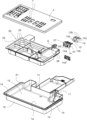
FIG. 1 shows an exploded view of the collection tray and of the components supported thereby;
FIG. 2 shows a schematic view of the coffee machine;
FIG. 3 shows a lateral raised view of the collection tray in a vertical section connected to the coffee machine;
FIG. 4 shows a lateral raised view of the collection tray in a vertical section;
FIG. 5 shows a front view of the tray in a vertical section;
DETAILED DESCRIPTION OF THE ILLUSTRATED EMBODIMENTS
With reference to the figures mentioned, a coffee machine 2 is shown that has at the front an extractable collection tray 1 for the discharged liquid/steam produced by the coffee machine 2.
The collection tray 1 in particular is positioned at the base of the front wall 6 of the frame of the coffee machine 2.
The collection tray 1 has a main body formed by a bottom 1 a, a front wall 1 b, a back wall 1 c and sides 1 d that bound an open upper side.
The coffee machine 2 comprises in a known manner a hydraulic circuit (not shown) comprising a water tank, a feed pump, at least one boiler that is able to generate hot water/steam and a brewing unit.
The brewing unit is connected to an external dispenser 3 that extends in front of the front wall 6 of the frame of the coffee machine 2 at a certain height above a resting plane 4 for resting the cups 5, which resting plane 4 is positioned to cover the open upper side of the collection tray 1.
The cup resting plane 4 has slits 7 to permit draining into the tray 1 of the residual drops of coffee that are possibly exiting the external dispenser 3 at the end of the dispensing cycle.
The tray 1 has a rear portion engaged in a space 9 that opens at the base of the front wall 6 of the frame of the coffee machine 2.
The tray 1 is connected by form coupling with the space 9 from which it is guidingly extracted with a horizontal translation movement in a rear-front direction.
The tray 1 has, at its rear portion, a connector 8 that is vertically connected in a sealed connection with a water/steam discharge conduit 40 above present in the coffee machine 1.
Water/steam that remains in the brewing unit generally flows into the discharge conduit 40 of the coffee machine 2 and into the connected circuits at the end of the normal dispensing cycle.
Also water/steam can possibly flow into the discharge conduit of the coffee machine 2 that circulate in a washing cycle of the inner components of the coffee machine or of accessories that are connectable to the coffee machine, such as for example milk emulsifiers for producing cappuccino or latte.
The collection tray 1 comprises a primary collection compartment 10, a secondary collection compartment 11, an overflow 12 of the primary collection compartment 10 for discharging the liquid into the secondary collection compartment 11, and at least two electrical conductors 13 positioned in the secondary collection compartment 11.
The secondary collection compartment 11 extends at least partially into the rear portion of the collection tray 1 and has a volume that is noticeably less than that of the primary collection compartment 10.
The two electrical conductors 13 are assembled on an oscillating support 14 for connection with two electrical contacts 15 of a detection electrical circuit 16 for detecting the liquid level present in the secondary collection compartment 11.
The two electrical contacts 15 are positioned in a housing 17 of the space 9 where the two electrical conductors 13 are inserted.
Other contacts 15′ can be inserted into the housing 17, which contacts 15′ are for example used to activate a signalling circuit for signalling the presence of the tray 1.
The oscillating support 14 is guided in a vertical oscillation direction.
The two electrical conductors 13, which are constrained stiffly on the oscillating support 14, are arranged at the same height in the secondary collection compartment 11.
The support 14 is subjected to an elastic strain towards a stroke end 18 present in a coffee machine 2.
In particular, the two contacts 15 are provided on elastically yielding metal elements 19 that stress the support 14 towards the stroke end 18.
The support 14 is subjected to a vertical elastic strain that always arranges the support 14 at a predetermined height and consequently always arranges the electrical conductors 13 at a predetermined height in the secondary collection compartment 11.
The stroke end 18 in the case illustrated is a wall of the housing 17, in particular the roof of the housing 17.
The electrical conductors 13 are shaped sheets comprising a front end 13 a that extends vertically into the secondary collection compartment 11 and a rear end 13 b that surmounts the secondary collection compartment 11 and extends into the housing 17.
The oscillating support 14 has a primary body 14 a placed in the secondary collection compartment 11 and a rear horizontal wing 14 b that surmounts the secondary collection compartment 11 and extends into the housing 17.
The primary body 14 a has in turn a through vertical central space 14 c in which a cap 14 d is housed.
The metal conductors 13 have an intermediate portion 13 c interposed between the cap 14 d and the wall of the space 14 c, the front end 13 a extending below the primary body 14 a, and the rear end 13 b wound around the rear horizontal wing 14 b.
The lower part of the rear end 13 of the metal conductors 13 is adapted to interacting with the corresponding electrical contact 15 below.
The cap 14 also has the function of breaking the waves that may be created in the secondary collection compartment 11.
The collection tray 1 has a frame 20 on which the oscillating support 14 is assembled.
The frame 20 is structurally independent of the main body of the collection tray 1.
The frame 20 has one or more vertical guide pins 24 on which specific through vertical holes are placed slidably 25 that are obtained at the front in the primary body 14 a of the oscillating support 14, and of the retaining seats 26 to which they are hooked with the possibility of vertical sliding of the snap-fit teeth 27 that also extend from the primary body 14 a of the oscillating support 14.
The frame 20 has a rest frame 22 on a perimeter shoulder 21 of the main body of the collection tray 1, and of the wave breaker walls 23 that extend inside the primary collection compartment 10.
The connector 8 is preferably integrated directly into the frame 20.
The advantage of the invention lies in the fact that the position of the metal conductors 13 is not stiffly connected to the position of the connector 8.
Then, when the collection tray 1 is introduced into the space 9 to connect the collection tray 1 electrically and hydraulically to the coffee machine 2, when the correct position of the connector 8 has been found also the electrical conductors 13 find the correct position through the effect of the settling of the position of the oscillating support 14 induced by the upward vertical elastic force with which the electrical contacts 15 push the electrical conductors 13 against the stroke end 18.
On the other side, the end position of the electrical conductors 13 will always be the same, so that recognition of the threshold level of the water in the secondary collection compartment 11 is always guaranteed.
The operation of the collection tray 1 is as follows.
Once level L1 is reached in the primary collection compartment 10, the liquid starts to overflow from the overflow 12 and enter the secondary collection compartment 11, which, having limited capacity, causes a rapid increase in level to a value L2 at which the electrical conductors 13 are licked by the liquid, which thus closes the electrical circuit 16.
The electrical circuit 16 generates a signal that is perceptible to the user, for example a message on the display from the coffee machine 2.
At this point the user extracts the collection tray 1 from the coffee machine 2, removes the cup resting plane 4 from the main body of the collection tray 1, possibly also removes the frame 20 from the main body of the collection tray 1 and empties the liquid contained in the main body of the collection tray 1.
The cup resting plane 4, the frame 20 and the main body of the collection tray 1, being structurally independent elements, can be handled singly for cleaning.
The collection tray and the coffee machine that incorporates the collection tray as conceived herein are susceptible to many modifications and variations, all falling within the scope of the inventive concept; further, all the details are replaceable by technically equivalent elements.
In practice the materials used, as well as the dimensions, can be any according to the needs and the state of the art.

Claims (18)

The invention claimed is:
1. A coffee machine (2) comprising:
an enclosure;
a collection tray (1) for discharged liquid/steam of the coffee machine (2), the collection tray (1) comprising:
a primary collection compartment (10);
a secondary collection compartment (11);
an overflow (12) of said primary collection compartment (10) for discharging the liquid into the secondary collection compartment (11);
at least two electrical conductors (13) positioned in said secondary collection compartment (11) and assembled on an oscillating support (14) and configured for connection with two electrical contacts (15) of an electric circuit (16) of the coffee machine (2) for detecting a level of liquid contained in said secondary collection compartment (11); and
a hydraulic connector (8) configured for sealed connection with an external water/steam discharge conduit (40) of the coffee machine (2);
wherein the oscillating support (14) is configured for vertical oscillation to enable a position of the two electrical conductors (13) to be movable relative to a position of the hydraulic connector (8); and
a dispenser (3) that extends from a wall of the enclosure, above the collection tray (1).
2. The coffee machine (2) according to claim 1, wherein said electrical conductors (13) are positioned at a same height in said secondary collection compartment (11).
3. The coffee machine (2) according to claim 1, further comprising a housing (17) for said electrical conductors (13) where said electrical contacts (15) are present.
4. The coffee machine (2) according to claim 1, wherein said electrical conductors (13) are positioned at a predetermined height in said secondary collection compartment (11) due to said oscillating support (14) being subjected to an elastic strain towards a stroke end (18).
5. The coffee machine (2) according to claim 4, wherein said electrical contacts (15) are provided on elastically yielding metal elements (19) that strain said oscillating support (14) towards said stroke end (18).
6. The coffee machine (2) according to claim 5, wherein said stroke end (18) is a wall of a housing (17) for said electrical conductors (13) where said electrical contacts (15) are present.
7. The coffee machine (2) according to claim 6, wherein said electrical conductors (13) are shaped sheets comprising one end (13 a) that extends into said secondary collection compartment (11) and one end (13 b) that extends into said housing (17).
8. The coffee machine (2) according to claim 1, wherein said oscillating support (14) is guided in a vertical oscillation direction.
9. The coffee machine (2) according to claim 1, wherein said oscillating support (14) is assembled on a structurally independent frame (20) of the collection tray (1), where the structurally independent frame (20) is structurally independent of a main body of the collection tray (1).
10. The coffee machine (2) according to claim 9, wherein said frame (20) has wave breaker walls (23) that extend into said primary collection compartment (10).
11. The coffee machine (2) according to claim 9, wherein said hydraulic connector (8) is configured for sealed connection of said primary collection compartment (10) to said water/steam discharge conduit (40) of said coffee machine (2).
12. The coffee machine (2) according to claim 11, wherein said hydraulic connector (8) is integrated into said frame (20).
13. The coffee machine (2) according to claim 1, wherein said collection tray (1) comprises a structurally independent cup resting plane (4), where the structurally independent cup resting frame (4) is structurally independent of a main body of the collection tray (1).
14. The coffee machine (2) according to claim 1, wherein the primary collection compartment (10), the secondary collection compartment (11), and the overflow (12) are configured so that:
upon liquid reaching a predetermined level in the primary collection compartment (10), the liquid starts to overflow from the overflow (12) into the secondary collection compartment (11); and
upon liquid reaching a predetermined level in the secondary collection compartment (11), the two electrical conductors (13) are contacted by the liquid, which closes the electric circuit (16).
15. The coffee machine (2) according to claim 1, wherein the secondary collection compartment (11) is smaller in volume than the primary collection compartment (10), and all liquid drainage and drippings of the coffee machine (2) first enter the primary collection compartment (10).
16. The coffee machine (2) according to claim 1, wherein the collection tray (1) is configured so that, when the collection tray (1) is introduced for electrical and hydraulic connection to the coffee machine (2), and the hydraulic connector (8) is connected to the water/steam discharge conduit (40), the electrical conductors (13) find positional alignment for connection with said electrical contacts (15) of said electric circuit (16) through positioning of the oscillating support (14).
17. The coffee machine (2) according to claim 1, wherein the hydraulic connector (8) is integrated directly into a frame (20) of the collection tray (1).
18. A coffee machine (2) comprising a collection tray (1) for discharged liquid/steam of the coffee machine (2), the collection tray (1) comprising:
a primary collection compartment (10),
a secondary collection compartment (11), smaller in volume than the primary collection compartment (10), where all liquid drainage and drippings of the coffee machine (2) first enter the primary collection compartment (10),
an overflow (12) of said primary collection compartment (10) for discharging the liquid into the secondary collection compartment (11),
a hydraulic connector (8) configured for sealed connection with a water/steam discharge conduit (40) of the coffee machine (2), and
at least two electrical conductors (13) positioned in said secondary collection compartment (11) and assembled on an oscillating support (14) for connection with two electrical contacts (15) of an external electric circuit (16) for detecting a level of liquid contained in said secondary collection compartment (11);
wherein the oscillating support (14) is configured for vertical oscillation to enable a position of the two electrical conductors (13) to be movable relative to a position of the hydraulic connector (8);
wherein the primary collection compartment (10), the secondary collection compartment (11), and the overflow (12) are configured so that:
upon liquid reaching a predetermined level in the primary collection compartment (10), the liquid starts to overflow from the overflow (12) into the secondary collection compartment (11); and
upon liquid reaching a predetermined level in the secondary collection compartment (11), the two electrical conductors (13) are contacted by the liquid, which closes the electric circuit (16); and
wherein the collection tray (1) is configured so that, when the collection tray (1) is introduced for electrical and hydraulic connection to the coffee machine (2), and the hydraulic connector (8) is connected to the water/steam discharge conduit (40), the electrical conductors (13) find positional alignment for connection with said electrical contacts (15) of said electric circuit (16) through positioning of the oscillating support (14).
US16/963,284 2018-03-05 2019-02-28 Collection tray for discharged liquid/steam of a coffee machine that incorporates said collection tray Active 2039-11-28 US11684202B2 (en)

Applications Claiming Priority (3)

Application Number Priority Date Filing Date Title
IT102018000003262A IT201800003262A1 (en) 2018-03-05 2018-03-05 DISCHARGE LIQUID / STEAM COLLECTION CONTAINER AND COFFEE MACHINE INCORPORATING THIS COLLECTION CONTAINER
IT102018000003262 2018-03-05
PCT/EP2019/054961 WO2019170508A1 (en) 2018-03-05 2019-02-28 Collection tray for discharged liquid/steam of a coffee machine that incorporates said collection tray

Publications (2)

Publication Number Publication Date
US20210045573A1 US20210045573A1 (en) 2021-02-18
US11684202B2 true US11684202B2 (en) 2023-06-27

Family

ID=62386741

Family Applications (1)

Application Number Title Priority Date Filing Date
US16/963,284 Active 2039-11-28 US11684202B2 (en) 2018-03-05 2019-02-28 Collection tray for discharged liquid/steam of a coffee machine that incorporates said collection tray

Country Status (6)

Country Link
US (1) US11684202B2 (en)
EP (1) EP3723561B1 (en)
KR (1) KR20200130243A (en)
AU (1) AU2019232332A1 (en)
IT (1) IT201800003262A1 (en)
WO (1) WO2019170508A1 (en)

Families Citing this family (1)

* Cited by examiner, † Cited by third party
Publication number Priority date Publication date Assignee Title
CN115474872A (en) * 2021-06-15 2022-12-16 深圳银星智能集团股份有限公司 Maintenance stations and cleaning systems

Citations (15)

* Cited by examiner, † Cited by third party
Publication number Priority date Publication date Assignee Title
US4591839A (en) * 1982-05-20 1986-05-27 Gulf & Western Manufacturing Company System for detecting low liquid level and probe therefor
US6766729B2 (en) * 2000-03-27 2004-07-27 Seb S.A. Infusion machine
DE10330734A1 (en) 2003-07-07 2005-02-17 Miele & Cie. Kg Method for detecting full condition of removable drip tray in drinks preparation machine has electrical contacts on tray which contact others in outer housing to signal condition
US7182017B1 (en) * 2002-04-18 2007-02-27 Bunn-O-Matic Corporation Beverage server with beverage detector
US20080226783A1 (en) * 2004-01-21 2008-09-18 Danny Lavie Device Method and System for the Application of Content on to the Surface of a Beverage
US20090236364A1 (en) * 2008-03-20 2009-09-24 Imi Cornelius Inc. Apparatus for attaching a drip tray to a beverage dispenser
US20100326282A1 (en) * 2006-10-20 2010-12-30 Carlo Carbonini Device for regulating the level of a liquid in a boiler of a coffee machine
US7997187B2 (en) * 2007-03-09 2011-08-16 Hamilton Beach Brands, Inc Brewed beverage maker
US20120186457A1 (en) * 2009-07-30 2012-07-26 Nestec S.A. Beverage production machine with antivibration drip tray assembly
US20130036815A1 (en) * 2010-04-27 2013-02-14 Nestec S.A. Beverage machine with integrated ultrasonic transceiver
US20140305927A1 (en) * 2010-11-02 2014-10-16 Piatto Technologies, Inc. Heated or cooled dishware and drinkware
US20140352802A1 (en) * 2011-12-12 2014-12-04 Nestec S.A. Drip tray for beverages dispenser
US20150245723A1 (en) * 2010-11-02 2015-09-03 Ember Technologies, Inc. Heated or cooled dishware and drinkware
US20170042373A1 (en) * 2010-11-02 2017-02-16 Ember Technologies, Inc. Heated or cooled dishware and drinkware and food containers
EP3153077A1 (en) 2015-10-05 2017-04-12 Eugster/Frismag AG Device for preparing beverages

Patent Citations (16)

* Cited by examiner, † Cited by third party
Publication number Priority date Publication date Assignee Title
US4591839A (en) * 1982-05-20 1986-05-27 Gulf & Western Manufacturing Company System for detecting low liquid level and probe therefor
US6766729B2 (en) * 2000-03-27 2004-07-27 Seb S.A. Infusion machine
US7182017B1 (en) * 2002-04-18 2007-02-27 Bunn-O-Matic Corporation Beverage server with beverage detector
DE10330734A1 (en) 2003-07-07 2005-02-17 Miele & Cie. Kg Method for detecting full condition of removable drip tray in drinks preparation machine has electrical contacts on tray which contact others in outer housing to signal condition
US20080226783A1 (en) * 2004-01-21 2008-09-18 Danny Lavie Device Method and System for the Application of Content on to the Surface of a Beverage
US20100326282A1 (en) * 2006-10-20 2010-12-30 Carlo Carbonini Device for regulating the level of a liquid in a boiler of a coffee machine
US7997187B2 (en) * 2007-03-09 2011-08-16 Hamilton Beach Brands, Inc Brewed beverage maker
US20090236364A1 (en) * 2008-03-20 2009-09-24 Imi Cornelius Inc. Apparatus for attaching a drip tray to a beverage dispenser
US20120186457A1 (en) * 2009-07-30 2012-07-26 Nestec S.A. Beverage production machine with antivibration drip tray assembly
US20130036815A1 (en) * 2010-04-27 2013-02-14 Nestec S.A. Beverage machine with integrated ultrasonic transceiver
US20140305927A1 (en) * 2010-11-02 2014-10-16 Piatto Technologies, Inc. Heated or cooled dishware and drinkware
US20150245723A1 (en) * 2010-11-02 2015-09-03 Ember Technologies, Inc. Heated or cooled dishware and drinkware
US20170042373A1 (en) * 2010-11-02 2017-02-16 Ember Technologies, Inc. Heated or cooled dishware and drinkware and food containers
US20140352802A1 (en) * 2011-12-12 2014-12-04 Nestec S.A. Drip tray for beverages dispenser
US9198536B2 (en) * 2011-12-12 2015-12-01 Nestec S.A. Drip tray for beverages dispenser
EP3153077A1 (en) 2015-10-05 2017-04-12 Eugster/Frismag AG Device for preparing beverages

Non-Patent Citations (4)

* Cited by examiner, † Cited by third party
Title
English translation; European Published Application No. EP3153077; Publication Date: Apr. 12, 2017; 16 pages.
English translation; German Published Application No. DE10330734; Publication Date: Feb. 17, 2005; 11 pages.
International Search Report dated May 8, 2019; International Application No. PCT/EP2019/054961; International Filing Date: Feb. 28, 2019; 3 pages.
Written Opinion dated May 8, 2019; International Application No. PCT/EP2019/054961; International Filing Date: Feb. 28, 2019; 5 pages.

Also Published As

Publication number Publication date
US20210045573A1 (en) 2021-02-18
EP3723561B1 (en) 2021-11-03
WO2019170508A1 (en) 2019-09-12
IT201800003262A1 (en) 2019-09-05
KR20200130243A (en) 2020-11-18
AU2019232332A1 (en) 2020-08-06
EP3723561A1 (en) 2020-10-21

Similar Documents

Publication Publication Date Title
JP6271439B2 (en) Drip tray for beverage dispenser
EP4081081B1 (en) Coffee machine, closing and/or tamping system and valve arrangement suitable for use in a coffee machine
US11684202B2 (en) Collection tray for discharged liquid/steam of a coffee machine that incorporates said collection tray
EP4081082B1 (en) Coffee machine, tamping system and valve arrangement suitable for use in a coffee machine
CN110313831B (en) Beverage preparation machine
WO2021130539A9 (en) Coffee machine and valve arrangement suitable for use in a coffee machine
EP1691650B1 (en) Beverage making device comprising a brewing chamber for enclosing a pad
EP1764437A1 (en) Detergent dispenser for a clothes washing machine
EP3678521B1 (en) A coffee machine with an improved filling system for the water reservoir
EP4054388B1 (en) A hot beverage preparing device
CN222285243U (en) Drinks preparation equipment
KR20180068631A (en) Pressure cooker
JP2019526400A (en) Beverage preparation machine discharge powder material collection container
EP4464207A1 (en) Coffee machine drip tray with integrated storage
CN213309224U (en) Low-cost food preparation machine
JP5799428B2 (en) Beverage extractor
EP3934491B1 (en) Funnel-shaped filter for moka coffee maker
RU2812796C2 (en) Drip-catcher for beverage machine and beverage machine containing drip-catcher
GB2174293A (en) Tea/coffee-making unit
HK1242152A1 (en) Machine for making beverages
HK1242152B (en) Machine for making beverages

Legal Events

Date Code Title Description
AS Assignment

Owner name: DE'LONGHI APPLIANCES S.R.L., SWITZERLAND

Free format text: ASSIGNMENT OF ASSIGNORS INTEREST;ASSIGNORS:DELONGHI, GIUSEPPE;NICOLETTI, NICOLA;EVANGELISTI, PAOLO;SIGNING DATES FROM 20200609 TO 20200618;REEL/FRAME:053249/0886

FEPP Fee payment procedure

Free format text: ENTITY STATUS SET TO UNDISCOUNTED (ORIGINAL EVENT CODE: BIG.); ENTITY STATUS OF PATENT OWNER: LARGE ENTITY

STPP Information on status: patent application and granting procedure in general

Free format text: APPLICATION DISPATCHED FROM PREEXAM, NOT YET DOCKETED

STPP Information on status: patent application and granting procedure in general

Free format text: DOCKETED NEW CASE - READY FOR EXAMINATION

STPP Information on status: patent application and granting procedure in general

Free format text: NON FINAL ACTION MAILED

STPP Information on status: patent application and granting procedure in general

Free format text: RESPONSE TO NON-FINAL OFFICE ACTION ENTERED AND FORWARDED TO EXAMINER

STCF Information on status: patent grant

Free format text: PATENTED CASE