US11684190B2 - Structure of straw and a set comprising such a straw - Google Patents
Structure of straw and a set comprising such a straw Download PDFInfo
- Publication number
- US11684190B2 US11684190B2 US17/146,505 US202117146505A US11684190B2 US 11684190 B2 US11684190 B2 US 11684190B2 US 202117146505 A US202117146505 A US 202117146505A US 11684190 B2 US11684190 B2 US 11684190B2
- Authority
- US
- United States
- Prior art keywords
- fastener
- hole
- straw
- disposed
- connecting member
- Prior art date
- Legal status (The legal status is an assumption and is not a legal conclusion. Google has not performed a legal analysis and makes no representation as to the accuracy of the status listed.)
- Active, expires
Links
- 239000010902 straw Substances 0.000 title claims abstract description 92
- 230000003670 easy-to-clean Effects 0.000 description 2
- 230000003466 anti-cipated effect Effects 0.000 description 1
- 230000008878 coupling Effects 0.000 description 1
- 238000010168 coupling process Methods 0.000 description 1
- 238000005859 coupling reaction Methods 0.000 description 1
- 239000000835 fiber Substances 0.000 description 1
- 239000011521 glass Substances 0.000 description 1
- 239000000463 material Substances 0.000 description 1
- 238000000034 method Methods 0.000 description 1
- 238000012986 modification Methods 0.000 description 1
- 230000004048 modification Effects 0.000 description 1
- 229920001296 polysiloxane Polymers 0.000 description 1
- 229910001220 stainless steel Inorganic materials 0.000 description 1
- 239000010935 stainless steel Substances 0.000 description 1
Images


Classifications
-
- A—HUMAN NECESSITIES
- A47—FURNITURE; DOMESTIC ARTICLES OR APPLIANCES; COFFEE MILLS; SPICE MILLS; SUCTION CLEANERS IN GENERAL
- A47G—HOUSEHOLD OR TABLE EQUIPMENT
- A47G21/00—Table-ware
- A47G21/18—Drinking straws or the like
Definitions
- the present disclosure generally relates to an improved structure of straw, particularly, to an improved structure of straw with a connecting member.
- plastic straws including paper straws, or straws made of other fibers
- straws made of other fibers are single-use straws. Therefore, reusable straws made of glass, stainless steel, or silicone are anticipated.
- Taiwanese Utility Patent No. M576836 disclosed an environmentally friendly straw which can be disassembled. The straw may be taken apart as flattened mode, then cleaned and reassembled back to straw mode, but the straw of Taiwanese Utility Patent No. M576836 is not easy to be reassembled.
- the present inventive concept provides an improved structure of a straw with a connecting structure which is easy to use.
- the improved structure of a straw of the present inventive concept comprises a tubular body and a connecting member.
- the tubular body has a first end, a second end and openings, and each of the openings is formed at the first end and the second end, respectively; wherein the tubular body comprises a tube wall, which is disposed between the first end and the second end.
- the connecting member is disposed at the tube wall, wherein a thickness of the connecting member is thicker than a thickness of the tube wall; wherein the connecting member comprises a first fastener and a second fastener corresponding to the first fastener, and wherein the first fastener is coupled with the second fastener openably and closably.
- a length of the connecting member substantially equals to a length of the tube wall.
- the tube wall has an inner surface and an outer surface corresponding to the inner surface, wherein one side of the connecting member near the inner surface is configured to substantially align with the inner surface, so that the connecting member protrudes outwardly from the outer surface.
- the tubular body and the connecting member are formed in one piece.
- the tube wall has a first side and a second side corresponding to the first side, and wherein the first fastener is disposed at the first side and extends from the first end to the second end; and the second fastener is disposed at the second side and extends from the first end to the second end.
- the first fastener comprises a groove, and the groove is disposed at and along the first fastener; wherein the groove has a slit toward the second fastener.
- the second fastener comprises a protruding member, the protruding member is disposed at and along the second fastener; wherein the protruding member is toward the first fastener.
- the first fastener further comprises two auxiliary members, and each of the auxiliary members is disposed at each side of the slit along the first fastener; wherein each of the auxiliary members extends toward the second fastener.
- the protruding member comprises a first protruding part and a second protruding part, wherein the first protruding part is disposed along the second fastener and the second protruding part is disposed on the first protruding part along the second fastener, and wherein the first protruding part substantially corresponds to the auxiliary members and the second protruding part substantially corresponds to the groove.
- the second protruding part has an expanding part, wherein a width of the expanding part is larger than a width of the first protruding part.
- the width of the expanding part is not larger than a width of the connecting member.
- the two auxiliary member forms a curved structure extending from the inner surface and the outer surface of the tube wall, and a hook is formed at an outward end of each of the two auxiliary members and a hook point of the hook faces the groove.
- a spacing between the two hook point is smaller than the width of the expanding part but not smaller than the width of the first protruding part.
- the present inventive concept further provides a set comprising a first straw with the improved structure of a straw of the present inventive concept and an assembly tool.
- the assembly tool comprises a body, a first through hole and a second through hole.
- the first through hole is disposed through the body, wherein the first through hole has a shape corresponding to an outer contour of the tubular body of the first straw; and the second through hole is disposed through the body, wherein the second through hole is beside the first through hole and integrates to the first through hole, and wherein the second through hole has a shape corresponding to an outer contour of the connecting member of the first straw.
- the first through hole has a first diameter substantially the same as an inside diameter of the tubular body.
- the second through hole has a second diameter substantially the same as a width of the connecting member when the first fastener is coupled with the second fastener.
- the assembly tool further comprises a storage case, wherein the storage case is connected to the body.
- the assembly tool further comprises a third through hole, a fourth through hole and a spacing part.
- the third through hole is disposed through the body.
- the fourth through hole is disposed through the body, wherein the fourth through hole is beside the third through hole and integrates to the third through hole; and the spacing part is disposed between the integrated first through hole and second through hole and the integrated third through hole and fourth through hole.
- the third through hole has a third diameter smaller or larger than the first diameter, or the fourth through hole has a fourth diameter smaller or larger than the second diameter.
- the set of the present inventive concept further comprises a second straw with the improved structure of a straw of the present inventive concept, wherein the third through hole has a shape corresponding to an outer contour of the tubular body of the second straw; and the fourth through hole has a shape corresponding to an outer contour of the connecting member of the second straw.
- the third through hole has a third diameter smaller or larger than the first diameter, or the fourth through hole has a fourth diameter smaller or larger than the second diameter.
- the assembly tool further comprises a fifth through hole and a spacing part.
- the fifth through hole is disposed through the body; wherein the fifth through hole is beside the second through hole and integrates to the second through hole and the spacing part is disposed between the first through hole and the fifth through hole.
- the fifth through hole has a fifth diameter smaller or larger than the first diameter.
- the set of the present inventive concept further comprises a second straw with the improved structure of a straw of the present inventive concept, wherein the fifth through hole has a shape corresponding to an outer contour of the tubular body of the second straw; and the second through hole has a shape corresponding to an outer contour of the connecting member of the second straw.
- the fifth through hole has a fifth diameter smaller or larger than the first diameter.
- the present inventive concept provides an improved structure of a straw comprising a tubular body and a connecting member, wherein the connecting member is disposed at the tube wall and the thickness of the connecting member is larger than that of the tube wall. Consequently, the thicker connecting member enables the first fastener being coupled with the second fastener openably and closably more easily.
- the assembly tool of the present inventive concept has a structure corresponding to the improved structure of a straw of the present inventive concept, which enables users to couple the first fastener with the second fastener of the straw in a short time.
- the set comprising the straw with the improved structure of a straw of the present inventive concept and the assembly tool improve efficiency and convenience for user to use a reusable straw.
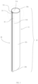
- FIG. 1 is a structure schematic view of an improved structure of a straw according to the present inventive concept
- FIG. 2 is an enlarged view of a portion of FIG. 1 and illustrating the connecting member of the improved structure of a straw according to the present inventive concept;
- FIG. 3 is a top view illustrating the improved structure of a straw being in use according to the present inventive concept
- FIG. 4 is an another view illustrating the improved structure of a straw being in use according to the present inventive concept
- FIG. 5 is a structure schematic view of a set according to the present inventive concept
- FIG. 6 is a structure schematic view of an assembly tool 30 according to an embodiment of the present inventive concept.
- FIG. 7 is a structure schematic view of an assembly tool according to an another embodiment of the present inventive concept.
- exemplary or “embodiment” is used herein to mean serving as an example, instance, or illustration. Any aspect or design described herein as exemplary or an embodiment is not necessarily to be construed as preferred or advantageous over other aspects or designs. Rather, use of the word “exemplary” or “embodiment” is intended to present concepts and techniques in a concrete fashion.
- the term “or” is intended to mean an inclusive “or” rather than an exclusive “or.” That is, unless specified otherwise or clear from context, “X employs A or B” is intended to mean any of the natural inclusive permutations. That is, if X employs A; X employs B; or X employs both A and B, then “X employs A or B” is satisfied under any of the foregoing instances.
- the articles “a” and “an” as used in this application and the appended claims should generally be construed to mean “one or more,” unless specified otherwise or clear from context to be directed to a singular form.
- FIG. 1 is a structure schematic view of an improved structure of a straw according to the present inventive concept
- FIG. 2 is an enlarged view of a portion of FIG. 1 and illustrating the connecting member of the improved structure of a straw according to the present inventive concept
- FIG. 3 is a top view illustrating the improved structure of a straw being in use according to the present inventive concept.
- the present inventive concept provides an improved structure of a straw which comprises a tubular body 10 and a connecting member 20 .
- the tubular body 10 may have a first end 10 a , a second end 10 b and openings, and each of the openings may be formed at the first end 10 a and the second end 10 b , respectively.
- the tubular body 10 may further comprise a tube wall 11 .
- the tube wall 11 may be disposed between the first end 10 a and the second end 10 b.
- The may be disposed at the tube wall 11 , wherein a thickness t 2 of the connecting member 20 may be thicker than a thickness t 1 of the tube wall 11 .
- the connecting member 20 may further comprise a first fastener 21 and a second fastener 22 corresponding to the first fastener 21 , and wherein the first fastener 21 may be coupled with the second fastener 22 openably and closably.
- a length of the connecting member 20 may substantially equal to a length of the tube wall 11 .
- the tube wall 11 may have an inner surface 11 a and an outer surface 11 b corresponding to the inner surface 11 a , wherein one side of the connecting member 20 near the inner surface may be configured to substantially align with the inner surface 11 a , so that the connecting member 20 may protrude outwardly from the outer surface 11 b , which is shown in FIG. 3 .
- tubular body 10 and the connecting member 20 may be formed in one piece.
- the tube wall 11 may have a first side 11 c and a second side 11 d corresponding to the first side 11 c , and wherein the first fastener 21 may be disposed at the first side 11 c and extend along from the first end 10 a to the second end 10 b ; and the second fastener 22 may be disposed at the second side 11 d and extend along from the first end 10 a to the second end 10 b.
- the first fastener 21 may comprise a groove 211 , and the groove 211 may be disposed at and along the first fastener 21 ; wherein the groove 211 may have a slit 211 a toward the second fastener 22 .
- the second fastener 22 may comprise a protruding member 221 , the protruding member 221 may be disposed at and along the second fastener 22 ; wherein the protruding member 221 may be toward the first fastener 21 .
- the first fastener 21 may further comprise two auxiliary members 212 , and each of the auxiliary members 212 may be disposed at each side of the slit 211 a along the first fastener 21 ; wherein each of the auxiliary members 212 may extend toward the second fastener 22 .
- the protruding member 221 may comprise a first protruding part 2211 and a second protruding part 2212 , wherein the first protruding part 2211 may be disposed along the second fastener 22 and the second protruding part 2212 may be disposed on the first protruding part 2211 along the second fastener 22 , and wherein the first protruding part 2211 may substantially correspond to the auxiliary members 212 and the second protruding part 2212 may substantially correspond to the groove 211 .
- the spacing between the two auxiliary members 212 may be equal to or less than the width of the first protruding part 2211 .
- the second protruding part 2212 may have an expanding part 22121 , wherein a width t 3 of the expanding part 22121 may be larger than a width t 4 of the first protruding part 2211 .
- the width t 3 of the expanding part 22121 may be not larger than, e.g. less than or equal to, a width t 2 of the connecting member 20 .
- the two auxiliary member 212 may form a curved structure extending from the inner surface 11 a and the outer surface 11 b of the tube wall 11 , and a hook 2121 may be formed at an outward end of each of the two auxiliary members 212 and a hook point of the hook 2121 may face the groove 211 .
- a spacing d between the two hook points may be smaller or less than the width t 3 of the expanding part 22121 , but not smaller than, e.g. larger than or equal to the width Li of the first protruding part 2211 .
- FIG. 3 is a top view illustrating the improved structure of a straw being in use according to the present inventive concept.
- the second protruding part 2212 of the protruding member 221 may be inserted into the groove 211 .
- the auxiliary members 212 may engage the first protruding part 2211 .
- each of the auxiliary members 212 may further comprise a hook 2121 and the second protruding part 2212 may have an expanding part 22121 .
- the width t 3 of the expanding part 22121 may be larger than the width t 4 of the first protruding part 2211 and a width of the second protruding part 2212 may be tapered towards the groove 211 .
- the distance between the spacing d may be varied. Distance between the spacing d between the two auxiliary members 212 may be measured between the surfaces of each auxiliary members 212 facing each other.
- the shortest distance between the spacing d between the two auxiliary members 212 may be larger than or equal to the width t 4 of the first protruding part 2211 , and the shortest distance between the spacing d between the two auxiliary members 212 may be equal to or less than the width t 3 of the expanding part 22121 , which enables the hook 2121 to fit against the second protruding part 2212 and/or the first protruding part 2211 more closely. By doing so, the first fastener 21 and the second fastener 22 may be engaged more tightly.
- the width t 2 of the connecting member 20 may be larger than the width t 1 of the tube wall 11 .
- FIG. 4 is an another view illustrating the improved structure of a straw being in use according to the present inventive concept.
- the improved structure of a straw may be made of flexible materials.
- users may detach the first fastener 21 from the second fastener 22 , open the straw and flatten the tube wall 11 . By doing so, users may clean the inner surface 11 a of the tube wall 11 .
- the present inventive concept further provides a set comprising a first straw 1 A with the improved structure of a straw of the present inventive concept and an assembly tool 30 .
- FIG. 5 is structure schematic view of a set according to the present inventive concept
- FIG. 6 is structure schematic view of an assembly tool 30 according to an embodiment of the present inventive concept.
- the assembly tool 30 may comprise a body 300 , a first through hole 310 and a second through hole 320 .
- the first through hole 310 may be disposed through the body 300 , wherein the first through hole 310 may have a shape corresponding to an outer contour of the tubular body 10 of the first straw 1 A; and the second through hole 320 may be disposed through the body 300 , wherein the second through hole 320 may be beside the first through hole 310 and integrates to the first through hole 310 , and wherein the second through hole 320 may have a shape corresponding to an outer contour of the connecting member 20 of the first straw 1 A.
- the first through hole 310 may have a first diameter R 1 substantially the same as an inside diameter t 1 of the tubular body 10 .
- the second through hole 320 may have a second diameter R 2 substantially the same as a width W 1 of the connecting member 20 when the first fastener 21 is coupled with the second fastener 22 (Please refer to FIG. 3 ).
- the first through hole 310 may be substantially adjacent to the tube body 10 and the second through hole 320 may be substantially adjacent to the connecting member 20 . Therefore, when the first straw 1 A passes through the first through hole 310 and the second through hole 320 , the edge of the second through hole 320 may be closely against the connecting member 20 .
- the structure of the second through hole 320 enables the first fastener 21 and the second fastener 22 to engage to each other to close the connecting member 20 .
- the assembly tool 30 may further comprise a storage case 40 , wherein the storage case 40 may be connected to the body 30 .
- the storage case 40 is used to store the straw 1 A.
- the assembly tool 30 may further comprise a third through hole 330 , a fourth through hole 340 and a spacing part 360 .
- the third through hole 330 may be disposed through the body 300 .
- the fourth through hole 340 may be disposed through the body 300 .
- the fourth through hole 340 may be beside the third through hole 330 and integrates to the third through hole 330 ; and the spacing part 360 may be disposed between the integrated first through hole 310 and second through hole 320 and the integrated third through hole 330 and fourth through hole 340 .
- the third through hole 330 may have a third diameter R 3 which is smaller or larger than or substantially equals to the first diameter R 1 of the first through hole 310
- the fourth through hole 340 may have a fourth diameter R 4 which is smaller or larger than or substantially equals to the second diameter R 2 of the second through hole 320 .
- the third diameter R 3 of the third through hole 330 may be substantially smaller or larger than the first diameter R 1 of the first through hole 310 and the fourth diameter R 4 of the fourth through hole 340 may be substantially smaller or larger than or equal to the second diameter R 2 of the second through hole 320 .
- the set of the present inventive concept may further comprise a second straw 1 B with the improved structure of a straw of the present inventive concept (as shown in FIG. 5 ).
- the third through hole has a shape corresponding to an outer contour of the tubular body of the second straw; and the fourth through hole has a shape corresponding to an outer contour of the connecting member of the second straw.
- the first through hole 310 may have a shape corresponding to an outer contour of the tubular body 10 of the first straw 1 A and wherein the second through hole 320 may have a shape corresponding to an outer contour of the connecting member 20 of the first straw 1 A.
- the third through hole 330 may have a shape corresponding to an outer contour of the tubular body 10 of the second straw 1 B and wherein the fourth through hole 340 may have a shape corresponding to an outer contour of the connecting member 20 of the second straw 1 B.
- the third through hole 330 may have a third diameter R 3 which is smaller or larger than or substantially equals to the first diameter R 1 of the first through hole 310
- the fourth through hole 340 may have a fourth diameter R 4 which is smaller or larger than or substantially equals to the second diameter R 2 of the second through hole 320 .
- the third diameter R 3 of the third through hole 330 may be substantially smaller or larger than the first diameter R 1 of the first through hole 310 and the fourth diameter R 4 of the fourth through hole 340 may be substantially smaller or larger than the second diameter R 2 of the second through hole 320 .
- the third diameter R 3 of the third through hole 330 may be substantially smaller than the first diameter R 1 of the first through hole 310 and the fourth diameter R 4 of the fourth through hole 340 may substantially equal to the second diameter R 2 of the second through hole 320 .
- FIG. 7 is a structure schematic view of an assembly tool according to an another embodiment of the present inventive concept.
- the assembly tool 30 may further comprise a fifth through hole 350 and a spacing part 360 .
- the fifth through hole 350 may be disposed through the body 300 ; wherein the fifth through hole 350 may be beside the second through hole 320 and integrates to the second through hole 320 and the spacing part 360 may be disposed between the first through hole 310 and the fifth through hole 350 .
- the fifth through hole 350 may have a fifth diameter R 5 which is smaller or larger than the first diameter R 1 of the first through hole 310 .
- the set of the present inventive concept may further comprise a second straw 1 B with the improved structure of a straw of the present inventive concept (as shown in FIG. 5 ).
- the first through hole 310 may have a shape corresponding to an outer contour of the tubular body 10 of the first straw 1 A and wherein the second through hole 320 may have a shape corresponding to an outer contour of the connecting member 20 of the first straw 1 A.
- the fifth through hole 350 may have a shape corresponding to an outer contour of the tubular body 10 of the second straw 1 B and wherein the second through hole 320 may have a shape corresponding to an outer contour of the connecting member 20 of the second straw 1 B.
- the fifth through hole 350 may have a fifth diameter R 5 which is smaller or larger than the first diameter R 1 of the first through hole 310 .
- the fifth diameter R 5 of the fifth through hole 350 may be substantially smaller than the first diameter R 1 of the first through hole 310 , but not limited.
- the present inventive concept provides an improved structure of a straw.
- the connecting member thereof is protruding out of the outer surface of the tube wall, so the users may press the protruding connecting member to make the first fastener coupling with the second fastener easily.
- the corresponding first fastener and the second fastener may fasten to each other securedly.
- the present inventive concept further provides a set comprising a first straw with the improved structure of a straw of the present inventive concept and an assembly tool.
- the assembly tool has integrated first through hole and second through hole may fit the contour of the improved structure of a straw of the present inventive concept properly. Accordingly, when the straws pass through the integrated first through hole and second through hole, the second through hole enables the first fastener engaged with the second fastener accurately and fast to close the connecting member.
- the improved structure of a straw and the set of the present inventive concept is not only easy-to-clean but also more easy-to-use.
Landscapes
- Table Equipment (AREA)
Abstract
Description
Claims (24)
Applications Claiming Priority (4)
| Application Number | Priority Date | Filing Date | Title |
|---|---|---|---|
| TW109200534 | 2020-01-14 | ||
| TW109200534U TWM593795U (en) | 2020-01-14 | 2020-01-14 | Straw improved structure |
| TW109203772U TWM611528U (en) | 2020-03-31 | 2020-03-31 | Locking member structure and assembly comprising the same |
| TW109203772 | 2020-03-31 |
Publications (2)
| Publication Number | Publication Date |
|---|---|
| US20210212490A1 US20210212490A1 (en) | 2021-07-15 |
| US11684190B2 true US11684190B2 (en) | 2023-06-27 |
Family
ID=76764159
Family Applications (1)
| Application Number | Title | Priority Date | Filing Date |
|---|---|---|---|
| US17/146,505 Active 2041-07-04 US11684190B2 (en) | 2020-01-14 | 2021-01-12 | Structure of straw and a set comprising such a straw |
Country Status (1)
| Country | Link |
|---|---|
| US (1) | US11684190B2 (en) |
Families Citing this family (4)
| Publication number | Priority date | Publication date | Assignee | Title |
|---|---|---|---|---|
| US11708846B2 (en) * | 2018-10-30 | 2023-07-25 | Trang Tran | Connection device |
| TWD210737S (en) * | 2020-01-14 | 2021-04-01 | 顏宏霖 | Part of a straw |
| TWM629460U (en) * | 2022-02-18 | 2022-07-11 | 蕭永牆 | Improved straw |
| USD999581S1 (en) * | 2023-02-16 | 2023-09-26 | Zelei LI | Straw |
Citations (2)
| Publication number | Priority date | Publication date | Assignee | Title |
|---|---|---|---|---|
| US20190338882A1 (en) * | 2016-12-01 | 2019-11-07 | Nippon Zipper Tubing Kabushiki Kaisha | Bundled protective member |
| WO2020054988A1 (en) * | 2018-09-13 | 2020-03-19 | 고연지 | Washable and assemblable silicone straw |
-
2021
- 2021-01-12 US US17/146,505 patent/US11684190B2/en active Active
Patent Citations (2)
| Publication number | Priority date | Publication date | Assignee | Title |
|---|---|---|---|---|
| US20190338882A1 (en) * | 2016-12-01 | 2019-11-07 | Nippon Zipper Tubing Kabushiki Kaisha | Bundled protective member |
| WO2020054988A1 (en) * | 2018-09-13 | 2020-03-19 | 고연지 | Washable and assemblable silicone straw |
Also Published As
| Publication number | Publication date |
|---|---|
| US20210212490A1 (en) | 2021-07-15 |
Similar Documents
| Publication | Publication Date | Title |
|---|---|---|
| US11684190B2 (en) | Structure of straw and a set comprising such a straw | |
| USD941337S1 (en) | Display screen or portion thereof with graphical user interface | |
| USD946609S1 (en) | Display screen or portion thereof with a graphical user interface | |
| USD489959S1 (en) | Compression latch | |
| USD612917S1 (en) | Watering hose | |
| USD1042854S1 (en) | Hook with strap | |
| US20090283651A1 (en) | Clip for Holding Toothbrushes and the Like | |
| US20200029713A1 (en) | Environmentally friendly drinking straw | |
| USD971407S1 (en) | Oral screening device | |
| USD911420S1 (en) | Activation button for use with a tripod for camera phones | |
| USD971090S1 (en) | Protective sleeve | |
| USD1086492S1 (en) | Lite | |
| JP2006010007A (en) | Pipe shaft and article for cleaning using the same | |
| CN211632704U (en) | Telescopic straw | |
| US20110042977A1 (en) | Dual-Segment Chopstick | |
| US20080185853A1 (en) | Dual-segment chopstick | |
| CN209090679U (en) | a combined straw | |
| USD971408S1 (en) | Oral screening device | |
| US20070017050A1 (en) | Roller-type paintbrush | |
| USD931525S1 (en) | Pipe cleaner | |
| CN211811176U (en) | Detachable buckle straw convenient to clean | |
| US20080196189A1 (en) | Multifunction eyeglass cleaner | |
| CN217065992U (en) | Glue-free portable straight-inserted chopsticks | |
| AU2021100163A4 (en) | Paintbrush and Coupling. | |
| TWM592268U (en) | Flexible environmental protection fitting kit |
Legal Events
| Date | Code | Title | Description |
|---|---|---|---|
| AS | Assignment |
Owner name: YEN, HONG-LIN, TAIWAN Free format text: ASSIGNMENT OF ASSIGNORS INTEREST;ASSIGNOR:YEN, HONG-LIN;REEL/FRAME:054882/0901 Effective date: 20201220 |
|
| FEPP | Fee payment procedure |
Free format text: ENTITY STATUS SET TO UNDISCOUNTED (ORIGINAL EVENT CODE: BIG.); ENTITY STATUS OF PATENT OWNER: SMALL ENTITY |
|
| FEPP | Fee payment procedure |
Free format text: ENTITY STATUS SET TO SMALL (ORIGINAL EVENT CODE: SMAL); ENTITY STATUS OF PATENT OWNER: SMALL ENTITY |
|
| STPP | Information on status: patent application and granting procedure in general |
Free format text: APPLICATION DISPATCHED FROM PREEXAM, NOT YET DOCKETED |
|
| STPP | Information on status: patent application and granting procedure in general |
Free format text: DOCKETED NEW CASE - READY FOR EXAMINATION |
|
| STPP | Information on status: patent application and granting procedure in general |
Free format text: NON FINAL ACTION MAILED |
|
| STPP | Information on status: patent application and granting procedure in general |
Free format text: RESPONSE TO NON-FINAL OFFICE ACTION ENTERED AND FORWARDED TO EXAMINER |
|
| STCF | Information on status: patent grant |
Free format text: PATENTED CASE |