US11680588B2 - Lubrication system for a compressor - Google Patents
Lubrication system for a compressor Download PDFInfo
- Publication number
- US11680588B2 US11680588B2 US17/236,719 US202117236719A US11680588B2 US 11680588 B2 US11680588 B2 US 11680588B2 US 202117236719 A US202117236719 A US 202117236719A US 11680588 B2 US11680588 B2 US 11680588B2
- Authority
- US
- United States
- Prior art keywords
- motor
- lubricant
- air
- reservoir
- air compressor
- Prior art date
- Legal status (The legal status is an assumption and is not a legal conclusion. Google has not performed a legal analysis and makes no representation as to the accuracy of the status listed.)
- Active, expires
Links
Images


Classifications
-
- F—MECHANICAL ENGINEERING; LIGHTING; HEATING; WEAPONS; BLASTING
- F15—FLUID-PRESSURE ACTUATORS; HYDRAULICS OR PNEUMATICS IN GENERAL
- F15B—SYSTEMS ACTING BY MEANS OF FLUIDS IN GENERAL; FLUID-PRESSURE ACTUATORS, e.g. SERVOMOTORS; DETAILS OF FLUID-PRESSURE SYSTEMS, NOT OTHERWISE PROVIDED FOR
- F15B11/00—Servomotor systems without provision for follow-up action; Circuits therefor
- F15B11/06—Servomotor systems without provision for follow-up action; Circuits therefor involving features specific to the use of a compressible medium, e.g. air, steam
- F15B11/072—Combined pneumatic-hydraulic systems
- F15B11/0725—Combined pneumatic-hydraulic systems with the driving energy being derived from a pneumatic system, a subsequent hydraulic system displacing or controlling the output element
-
- F—MECHANICAL ENGINEERING; LIGHTING; HEATING; WEAPONS; BLASTING
- F04—POSITIVE - DISPLACEMENT MACHINES FOR LIQUIDS; PUMPS FOR LIQUIDS OR ELASTIC FLUIDS
- F04C—ROTARY-PISTON, OR OSCILLATING-PISTON, POSITIVE-DISPLACEMENT MACHINES FOR LIQUIDS; ROTARY-PISTON, OR OSCILLATING-PISTON, POSITIVE-DISPLACEMENT PUMPS
- F04C18/00—Rotary-piston pumps specially adapted for elastic fluids
- F04C18/08—Rotary-piston pumps specially adapted for elastic fluids of intermeshing-engagement type, i.e. with engagement of co-operating members similar to that of toothed gearing
- F04C18/12—Rotary-piston pumps specially adapted for elastic fluids of intermeshing-engagement type, i.e. with engagement of co-operating members similar to that of toothed gearing of other than internal-axis type
- F04C18/14—Rotary-piston pumps specially adapted for elastic fluids of intermeshing-engagement type, i.e. with engagement of co-operating members similar to that of toothed gearing of other than internal-axis type with toothed rotary pistons
- F04C18/16—Rotary-piston pumps specially adapted for elastic fluids of intermeshing-engagement type, i.e. with engagement of co-operating members similar to that of toothed gearing of other than internal-axis type with toothed rotary pistons with helical teeth, e.g. chevron-shaped, screw type
-
- F—MECHANICAL ENGINEERING; LIGHTING; HEATING; WEAPONS; BLASTING
- F04—POSITIVE - DISPLACEMENT MACHINES FOR LIQUIDS; PUMPS FOR LIQUIDS OR ELASTIC FLUIDS
- F04C—ROTARY-PISTON, OR OSCILLATING-PISTON, POSITIVE-DISPLACEMENT MACHINES FOR LIQUIDS; ROTARY-PISTON, OR OSCILLATING-PISTON, POSITIVE-DISPLACEMENT PUMPS
- F04C29/00—Component parts, details or accessories of pumps or pumping installations, not provided for in groups F04C18/00 - F04C28/00
- F04C29/02—Lubrication; Lubricant separation
-
- F—MECHANICAL ENGINEERING; LIGHTING; HEATING; WEAPONS; BLASTING
- F04—POSITIVE - DISPLACEMENT MACHINES FOR LIQUIDS; PUMPS FOR LIQUIDS OR ELASTIC FLUIDS
- F04C—ROTARY-PISTON, OR OSCILLATING-PISTON, POSITIVE-DISPLACEMENT MACHINES FOR LIQUIDS; ROTARY-PISTON, OR OSCILLATING-PISTON, POSITIVE-DISPLACEMENT PUMPS
- F04C28/00—Control of, monitoring of, or safety arrangements for, pumps or pumping installations specially adapted for elastic fluids
- F04C28/24—Control of, monitoring of, or safety arrangements for, pumps or pumping installations specially adapted for elastic fluids characterised by using valves controlling pressure or flow rate, e.g. discharge valves or unloading valves
-
- F—MECHANICAL ENGINEERING; LIGHTING; HEATING; WEAPONS; BLASTING
- F04—POSITIVE - DISPLACEMENT MACHINES FOR LIQUIDS; PUMPS FOR LIQUIDS OR ELASTIC FLUIDS
- F04C—ROTARY-PISTON, OR OSCILLATING-PISTON, POSITIVE-DISPLACEMENT MACHINES FOR LIQUIDS; ROTARY-PISTON, OR OSCILLATING-PISTON, POSITIVE-DISPLACEMENT PUMPS
- F04C29/00—Component parts, details or accessories of pumps or pumping installations, not provided for in groups F04C18/00 - F04C28/00
- F04C29/0042—Driving elements, brakes, couplings, transmissions specially adapted for pumps
- F04C29/0085—Prime movers
-
- F—MECHANICAL ENGINEERING; LIGHTING; HEATING; WEAPONS; BLASTING
- F04—POSITIVE - DISPLACEMENT MACHINES FOR LIQUIDS; PUMPS FOR LIQUIDS OR ELASTIC FLUIDS
- F04C—ROTARY-PISTON, OR OSCILLATING-PISTON, POSITIVE-DISPLACEMENT MACHINES FOR LIQUIDS; ROTARY-PISTON, OR OSCILLATING-PISTON, POSITIVE-DISPLACEMENT PUMPS
- F04C29/00—Component parts, details or accessories of pumps or pumping installations, not provided for in groups F04C18/00 - F04C28/00
- F04C29/02—Lubrication; Lubricant separation
- F04C29/021—Control systems for the circulation of the lubricant
-
- F—MECHANICAL ENGINEERING; LIGHTING; HEATING; WEAPONS; BLASTING
- F04—POSITIVE - DISPLACEMENT MACHINES FOR LIQUIDS; PUMPS FOR LIQUIDS OR ELASTIC FLUIDS
- F04C—ROTARY-PISTON, OR OSCILLATING-PISTON, POSITIVE-DISPLACEMENT MACHINES FOR LIQUIDS; ROTARY-PISTON, OR OSCILLATING-PISTON, POSITIVE-DISPLACEMENT PUMPS
- F04C29/00—Component parts, details or accessories of pumps or pumping installations, not provided for in groups F04C18/00 - F04C28/00
- F04C29/02—Lubrication; Lubricant separation
- F04C29/026—Lubricant separation
-
- F—MECHANICAL ENGINEERING; LIGHTING; HEATING; WEAPONS; BLASTING
- F04—POSITIVE - DISPLACEMENT MACHINES FOR LIQUIDS; PUMPS FOR LIQUIDS OR ELASTIC FLUIDS
- F04C—ROTARY-PISTON, OR OSCILLATING-PISTON, POSITIVE-DISPLACEMENT MACHINES FOR LIQUIDS; ROTARY-PISTON, OR OSCILLATING-PISTON, POSITIVE-DISPLACEMENT PUMPS
- F04C29/00—Component parts, details or accessories of pumps or pumping installations, not provided for in groups F04C18/00 - F04C28/00
- F04C29/04—Heating; Cooling; Heat insulation
-
- F—MECHANICAL ENGINEERING; LIGHTING; HEATING; WEAPONS; BLASTING
- F15—FLUID-PRESSURE ACTUATORS; HYDRAULICS OR PNEUMATICS IN GENERAL
- F15B—SYSTEMS ACTING BY MEANS OF FLUIDS IN GENERAL; FLUID-PRESSURE ACTUATORS, e.g. SERVOMOTORS; DETAILS OF FLUID-PRESSURE SYSTEMS, NOT OTHERWISE PROVIDED FOR
- F15B1/00—Installations or systems with accumulators; Supply reservoir or sump assemblies
- F15B1/26—Supply reservoir or sump assemblies
- F15B1/265—Supply reservoir or sump assemblies with pressurised main reservoir
-
- F—MECHANICAL ENGINEERING; LIGHTING; HEATING; WEAPONS; BLASTING
- F15—FLUID-PRESSURE ACTUATORS; HYDRAULICS OR PNEUMATICS IN GENERAL
- F15B—SYSTEMS ACTING BY MEANS OF FLUIDS IN GENERAL; FLUID-PRESSURE ACTUATORS, e.g. SERVOMOTORS; DETAILS OF FLUID-PRESSURE SYSTEMS, NOT OTHERWISE PROVIDED FOR
- F15B11/00—Servomotor systems without provision for follow-up action; Circuits therefor
- F15B11/06—Servomotor systems without provision for follow-up action; Circuits therefor involving features specific to the use of a compressible medium, e.g. air, steam
- F15B11/072—Combined pneumatic-hydraulic systems
-
- F—MECHANICAL ENGINEERING; LIGHTING; HEATING; WEAPONS; BLASTING
- F04—POSITIVE - DISPLACEMENT MACHINES FOR LIQUIDS; PUMPS FOR LIQUIDS OR ELASTIC FLUIDS
- F04C—ROTARY-PISTON, OR OSCILLATING-PISTON, POSITIVE-DISPLACEMENT MACHINES FOR LIQUIDS; ROTARY-PISTON, OR OSCILLATING-PISTON, POSITIVE-DISPLACEMENT PUMPS
- F04C2210/00—Fluid
- F04C2210/10—Fluid working
- F04C2210/1005—Air
-
- F—MECHANICAL ENGINEERING; LIGHTING; HEATING; WEAPONS; BLASTING
- F04—POSITIVE - DISPLACEMENT MACHINES FOR LIQUIDS; PUMPS FOR LIQUIDS OR ELASTIC FLUIDS
- F04C—ROTARY-PISTON, OR OSCILLATING-PISTON, POSITIVE-DISPLACEMENT MACHINES FOR LIQUIDS; ROTARY-PISTON, OR OSCILLATING-PISTON, POSITIVE-DISPLACEMENT PUMPS
- F04C2210/00—Fluid
- F04C2210/22—Fluid gaseous, i.e. compressible
- F04C2210/221—Air
-
- F—MECHANICAL ENGINEERING; LIGHTING; HEATING; WEAPONS; BLASTING
- F04—POSITIVE - DISPLACEMENT MACHINES FOR LIQUIDS; PUMPS FOR LIQUIDS OR ELASTIC FLUIDS
- F04C—ROTARY-PISTON, OR OSCILLATING-PISTON, POSITIVE-DISPLACEMENT MACHINES FOR LIQUIDS; ROTARY-PISTON, OR OSCILLATING-PISTON, POSITIVE-DISPLACEMENT PUMPS
- F04C2240/00—Components
- F04C2240/80—Other components
- F04C2240/809—Lubricant sump
Definitions
- the present disclosure relates to compressors, and more particularly to lubrication systems for oil flooded screw compressors.
- Oil flooded screw compressors typically include a set of rotors or screws that require fluid (e.g., oil) to seal between the rotors and to remove heat generated during compression.
- the rotors are supported on bearings that also typically require lubrication.
- the required oil is supplied by an air/oil separator tank. Pressurized air discharged from the compressor flows into the separator tank, where entrained oil is separated from the air and collected in the tank.
- the separator tank is maintained at an elevated pressure while the compressor is operating, thereby driving oil to the compressor.
- Some machine operations e.g., down-the-hole hammer drilling
- high air pressure e.g., at or above 175 psi, and up to 500 psi in some cases
- air compressor oil lubricating system uses air pressure to drive oil through oil coolers, all system components must be able to withstand the maximum operating pressure used plus a safety margin.
- the maximum operating pressure increases, thereby requiring an increase in the size and complexity of cooling circuits that can withstand these operating pressures and still provide adequate cooling. Designing and fabricating large coolers that are capable of withstanding high operating pressures is difficult, and in some cases not economically feasible.
- an industrial machine includes a working tool; an air supply system for supplying pressurized air for operating the tool, the air supply system including an air compressor supplying pressurized air at an output; a drive system for driving at least the air compressor; and a lubrication system for supplying lubricant to the air compressor.
- the lubrication system includes a reservoir configured to support lubricant, the reservoir configured to receive pressurized air from the air compressor; and a motor operably coupled to the drive system and configured to receive pressurized lubricant, flow of lubricant driving the motor to transmit power to the drive train in at least one operating condition.
- a lubrication system for supplying lubricant to an air compressor.
- the air compressor is driven by a drive system.
- the lubrication system includes a separator reservoir configured to support lubricant and configured to receive pressurized air from the air compressor, the separator reservoir configured to separate lubricant from the air received from the air compressor; and a motor operably coupled to the drive system and configured to receive pressurized lubricant.
- the motor is configured to transmit power to the drive system in at least one operating condition.
- a lubrication system for supplying lubricant to an air compressor for a drill.
- the air compressor is driven by a drive system.
- the lubrication system includes a separator reservoir configured to support lubricant and configured to receive pressurized air from the air compressor, the separator reservoir configured to separate lubricant from the air received from the air compressor; a cooler configured to reduce a temperature of the lubricant being driven to the air compressor; and a motor operably coupled to the drive system and configured to receive pressurized lubricant.
- the motor is configured to transmit power to the drive system in a first mode in which pressure of the air in the reservoir is sufficient to drive the lubricant from the reservoir through the motor.
- the motor is configured to be driven by the drive system to drive the lubricant in a second mode in which pressure of the air in the reservoir is insufficient to drive the lubricant from the reservoir and through the motor.
- FIG. 1 is a side view of an industrial machine.
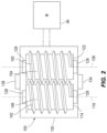
- FIG. 2 is a schematic view of an air compressor operable with the industrial machine of FIG. 1 .
- FIG. 3 is a schematic view of a lubrication system operable with the air compressor of FIG. 2 .
- FIG. 4 is a schematic view of a lubrication system according to another embodiment, operable with the air compressor of FIG. 2 .
- FIG. 5 is a schematic view of a lubrication system according to yet another embodiment, operable with the air compressor of FIG. 2 .
- FIG. 6 is a schematic view of a lubrication system according to still another embodiment, operable with the air compressor of FIG. 2 .
- FIG. 7 is a schematic view of a lubrication system according to yet another embodiment, operable with the air compressor of FIG. 2 .
- FIG. 8 is a schematic view of a lubrication system according to still another embodiment, operable with the air compressor of FIG. 2 .
- the present disclosure relates to a system for cooling and/or lubricating an air compressor.
- the system includes a regenerative circuit that is operable to reduce pressure of the cooling fluid/lubricant and is capable of capturing energy from the cooling fluid/lubricant to supplement a drive train, thereby increasing reliability and safety, lowering cost, and reducing power consumption.
- FIG. 1 illustrates a machine 10 .
- the machine 10 is a blasthole drill; however, in other embodiments, the machine 10 may be a different type of drill or any other type of machine requiring compressed air, including mining equipment, construction equipment, and the like.
- the illustrated blasthole drill 10 includes a drill tower 14 , a base 18 (e.g., a machinery house) supporting the drill tower 14 , an operator's cab 22 coupled to the base 18 , and traction devices (e.g., crawlers) 26 configured to move the drill 10 along a ground surface 34 .
- the drill tower 14 is coupled to and supports a drill pipe 38 (e.g., with a drill bit, not shown), which is configured to extend vertically downward through the ground 34 and into a borehole.
- the machine 10 further includes a drive train 42 for providing power from a prime mover 46 to various components of the machine, including the traction devices 26 and the drill pipe 38 .
- An air compressor 100 is supported by the base 18 and is operable to generate compressed air that may be used, for example, for flushing bit cuttings from the bottom of the borehole to the surface.
- a lubrication system 200 is also supported by the base 18 and is operable to provide oil to the air compressor 100 , as described below.
- an oil flooded rotary screw air compressor 100 includes a main rotor or screw 114 that rotates about a first axis 118 and a secondary rotor or screw 122 that rotates about a second axis 126 .
- the rotors 114 , 122 are each supported on low-friction bearings 128 and disposed in a stator housing 130 .
- the rotors 114 , 122 are driven by a power source (e.g., the prime mover 46 or a motor).
- the rotors 114 , 122 may be coupled to the prime mover 46 by any suitable power transfer mechanism, such as a transmission, power take-off shaft, torque converter, direct drive, and the like.
- the compressor 100 may include more than two rotors, or the compressor 100 may include a single rotor.
- the stator housing 130 includes an air inlet port 134 and an air outlet port 138 .
- the main rotor 114 has helical lobes 142 and grooves 146 along its length, while the secondary rotor 122 has corresponding helical lobes 150 and grooves 154 .
- Air flowing in through the inlet port 134 fills spaces between the helical lobes 142 , 150 on each rotor 114 , 122 . Rotation of the rotors 114 , 122 causes the air to be trapped between the lobes 142 , 150 and the stator housing 130 .
- the lobes 142 on the main rotor 114 roll into the grooves 154 on the secondary rotor 122 and the lobes 150 on the secondary rotor 122 roll into the grooves 146 on the main rotor 114 , thereby reducing the space occupied by the air and resulting in increased pressure. Compression continues until the inter-lobe spaces are exposed to the air outlet port 138 where the compressed air is discharged.
- the illustrated compressor 100 is a single stage compressor; however, in other embodiments, the compressor 100 may have multiple stages.
- the compressor 100 has a maximum output pressure at the air outlet port 138 of 500 psi. In other embodiments, the compressor 100 has a maximum output pressure at the air outlet port 138 less than 500 psi. In other embodiments, the compressor 100 has a maximum output pressure at the air outlet port 138 between 200 psi and 500 psi. In some embodiments, the compressor 100 has a maximum discharge volume of 3,800 cubic feet per minute (CFM). In other embodiments, the compressor 100 has a maximum discharge volume less than 3,800 CFM. In other embodiments, the compressor 100 has a maximum discharge volume between 1,000 CFM and 3,800 CFM.
- CFM cubic feet per minute
- FIG. 3 illustrates a lubrication system 200 , according to one embodiment, that can be used to supply lubricant to the compressor 200 illustrated in FIG. 1 .
- the lubricant is a petroleum-based or synthetic oil; in other embodiments, the lubricant may be any lubricant that is appropriate for use in a flooded compressor, such as the compressor 100 .
- the lubricant is supplied directly to the compressor 200 to lubricate and/or cool the components of the compressor 200 .
- the illustrated lubrication system 200 includes an air compressor receiver tank 212 and a cooler 216 . These components are coupled together by fluid transfer components, such as piping, valving, and/or metering devices. It should be understood that the arrangement, selection, and number of fluid transfer components may be varied as would be understood by one of ordinary skill in the art.
- the receiver tank 212 receives (either directly or indirectly) pressurized air from the air compressor and is a separator tank capable of separating lubricant from the pressurized air.
- a motor 222 (e.g., a fixed displacement hydraulic motor) is positioned between the receiver tank 212 and the cooler 216 .
- the motor 222 is coupled to the drive train 42 , and operation of the motor 222 provides additional power to the drive train 42 . That is, the motor 222 is capable of transmitting power to the drive train 42 .
- air pressure in the tank 212 may drive lubricant from the tank 212 and to the air compressor 100 , through the motor 222 and cooler 216 .
- the fluid drives the motor 222 , transmitting some power back to the drive train 42 .
- the power transmitted to the drive train may be in the form of rotational energy.
- the pressure of the fluid leaving the motor 222 is reduced before passing through the cooler 216 .
- Operational air pressure in the air tank 212 pushes hot lubricating oil from the air tank 212 to the motor 222 via connecting hoses and/or tubes.
- the motor 222 is connected to the air compressor prime mover drive train 42 . As the prime mover 46 rotates, the motor 222 rotates at a speed proportional to the prime mover 46 and driven air compressor 100 , thus ensuring lubricant flow from the air tank 212 to the air compressor 100 . In some operating conditions (e.g., when operational system pressure is high or above a threshold), the motor 222 is driven by flow of the pressurized lubricant.
- the pressure of the lubricant is reduced at the motor outlet as the potential energy of the lubricant is converted into rotational energy of the motor 222 that is transmitted back into the prime mover drivetrain 42 .
- the lubrication system 200 captures energy that is not necessary for cooling and supplies it back to the drive train 42 .
- an air system operating at 500 psi that requires an oil flow of 100 gallons per minute for cooling can regenerate 17.5 horsepower back into the drivetrain (minus inefficiencies) when the motor outlet to the oil cooler is 200 psi.
- the operation of the motor 222 (including the conditions in which it is activated to transmit power to the drive train 42 ) may vary depending on the operating conditions of the industrial machine and the lubrication system.
- the lubricant pressure exiting the motor 222 is reduced, thereby enabling the system 200 to be operated with components having a lower pressure rating.
- the use of lower-rated components reduces cost, increases reliability (e.g., due to less system fatigue), and increases safety.
- the motor 222 is capable of transitioning to operating as a lubricant pump in some operating conditions (e.g., when operational system pressure is low or below a threshold).
- the pump/motor 222 may be driven by the drive train 42 to ensure an adequate flow to the air compressor 100 for cooling and lubrication. That is, in some embodiments the connection between the drive train 42 and the motor 222 permits power transmission in two directions (i.e., the connection is bi-directional).
- the threshold at which the pump/motor 222 transitions may vary depending on the operating conditions of the industrial machine and the lubrication system.
- the motor 222 may act as a motor only, regardless of the system pressure. Stated another way, in some embodiments, the motor 222 may operate in a single mode as a motor transmitting power to the drive train 41 ; in other embodiments, the motor 222 may be a pump/motor that operates as a motor in a first mode and operates as a pump in a second mode.
- FIG. 4 illustrates a system 500 according to another embodiment.
- the system 500 is similar to the system 200 described above with respect to FIG. 3 , and similar components are illustrated with similar reference numbers, plus 300 or plus 500 . Some differences between the system 500 and the system 200 are described.
- the system 500 includes a variable displacement hydraulic motor 522 positioned between a tank 512 and a cooler 516 .
- the output requirements of the air system can vary, and often the speed of a compressor 400 must be adjusted accordingly. Changes in the speed of the compressor 400 impacts the flow of lubricant.
- the motor 522 can be adjusted to vary the amount of displaced fluid to match system flow and allow maximization of energy return to the drive train 542 .
- motor displacement can be adjusted to control outlet pressure from the motor 522 , thereby limiting pressure of the fluid passing to the cooler 516 .
- FIG. 5 illustrates a system 800 according to another embodiment.
- the system 800 is similar to the system 200 described above with respect to FIG. 3 , and similar components are illustrated with similar reference numbers, plus 600 or plus 800 . Some differences between the system 800 and the system 200 are described.
- the system 800 includes a motor 222 positioned between a tank 812 and a cooler 816 .
- a variable orifice 824 is positioned in parallel with the motor 222 . The variable orifice 824 reduces the effects of pressure and flow fluctuations, thereby increasing the working life of the cooler 816 and the motor 222 .
- variable orifice 824 is incorporated into the system 500 including a variable displacement motor 522 .
- the combination of the variable orifice 824 and variable displacement motor 522 can optimize pressure and flow through the system 800 to limit damaging pressure and flow fluctuations, while permitting adjustments to maximize energy return to a drive train 542 .
- FIG. 7 illustrates a system 1100 according to another embodiment.
- the system 1100 is similar to the system 200 described above with respect to FIG. 3 , and similar components are illustrated with similar reference numbers, plus 900 or plus 1100 . Some differences between the system 1100 and the system 200 are described.
- the system 1100 includes a motor 222 positioned between a tank 1112 and a cooler 1116 .
- a pressure reducing valve 1130 and relief valve 1134 are positioned downstream of a fixed displacement motor 222 .
- the valves 1130 , 1134 permit greater fluctuations in pressure and flow while also protecting the cooler 1116 .
- the valves 1130 , 1134 reduce constraints on the size of the motor 222 , permitting greater flexibility in selection of the motor 222 .
- the pressure reducing valve 1130 , a relief valve 1134 , and a variable orifice 1124 are incorporated into the system 500 including a variable displacement motor 522 .
- the valves 1130 , 1134 permit greater fluctuations in pressure and flow while also protecting the cooler 216 .
- the combination of the variable orifice 1124 and the variable displacement motor 522 can optimize pressure and flow through the system 1100 to limit damaging pressure and flow fluctuations, while permitting adjustments to maximize energy return to the drive train 1142 .
Landscapes
- Engineering & Computer Science (AREA)
- Mechanical Engineering (AREA)
- General Engineering & Computer Science (AREA)
- Physics & Mathematics (AREA)
- Fluid Mechanics (AREA)
- Compressor (AREA)
- Compressors, Vaccum Pumps And Other Relevant Systems (AREA)
Abstract
Description
Claims (24)
Priority Applications (1)
| Application Number | Priority Date | Filing Date | Title |
|---|---|---|---|
| US17/236,719 US11680588B2 (en) | 2020-04-21 | 2021-04-21 | Lubrication system for a compressor |
Applications Claiming Priority (2)
| Application Number | Priority Date | Filing Date | Title |
|---|---|---|---|
| US202063013334P | 2020-04-21 | 2020-04-21 | |
| US17/236,719 US11680588B2 (en) | 2020-04-21 | 2021-04-21 | Lubrication system for a compressor |
Publications (2)
| Publication Number | Publication Date |
|---|---|
| US20210324859A1 US20210324859A1 (en) | 2021-10-21 |
| US11680588B2 true US11680588B2 (en) | 2023-06-20 |
Family
ID=78081489
Family Applications (1)
| Application Number | Title | Priority Date | Filing Date |
|---|---|---|---|
| US17/236,719 Active 2041-05-23 US11680588B2 (en) | 2020-04-21 | 2021-04-21 | Lubrication system for a compressor |
Country Status (6)
| Country | Link |
|---|---|
| US (1) | US11680588B2 (en) |
| CN (2) | CN216665919U (en) |
| AU (1) | AU2021202410A1 (en) |
| CA (1) | CA3115914A1 (en) |
| CL (1) | CL2021001019A1 (en) |
| MX (1) | MX2021004604A (en) |
Families Citing this family (1)
| Publication number | Priority date | Publication date | Assignee | Title |
|---|---|---|---|---|
| AU2021202410A1 (en) * | 2020-04-21 | 2021-11-11 | Joy Global Surface Mining Inc | Lubrication system for a compressor |
Citations (38)
| Publication number | Priority date | Publication date | Assignee | Title |
|---|---|---|---|---|
| DE242255C (en) | ||||
| US3936249A (en) | 1973-11-26 | 1976-02-03 | Hokuetsu Kogyo Co., Ltd. | Rotary compressor of oil cooling type with appropriate oil discharge circuit |
| US4262775A (en) | 1979-05-07 | 1981-04-21 | Ingersoll-Rand Company | Oil supply means for a machine |
| US4394113A (en) | 1979-12-05 | 1983-07-19 | M.A.N. Maschinenfabrik Augsburg-Nurnberg Aktiengesellschaft | Lubrication and packing of a rotor-type compressor |
| US4964790A (en) | 1989-10-10 | 1990-10-23 | Sundstrand Corporation | Automatic regulation of balancing pressure in a screw compressor |
| EP0464315B1 (en) | 1990-06-30 | 1993-06-23 | KABUSHIKI KAISHA KOBE SEIKO SHO also known as Kobe Steel Ltd. | Oil-flooded screw compressor |
| JPH08121368A (en) | 1994-10-19 | 1996-05-14 | Hokuetsu Kogyo Co Ltd | Oil-cooled rotary compressor |
| JPH09100781A (en) | 1996-07-09 | 1997-04-15 | Kobe Steel Ltd | Oil cooled type compressor |
| US5765392A (en) | 1995-08-09 | 1998-06-16 | Sulzer-Escher Wyss Gmbh | Screw compressor apparatus for refrigerants with oils soluble in refrigerants |
| GB2367334A (en) | 2000-09-28 | 2002-04-03 | Ingersoll Rand Europ Sales Ltd | Active pressure vessel control system for a lubricant flooded air compressor |
| US6860730B2 (en) | 2002-05-20 | 2005-03-01 | Driltech Mission, Llc | Methods and apparatus for unloading a screw compressor |
| WO2005035989A1 (en) | 2003-10-15 | 2005-04-21 | Atlas Copco Airpower N.V. | Improved water-injected screw-type compressor |
| US6981855B2 (en) | 2002-09-30 | 2006-01-03 | Sandvik Ab | Drilling rig having a compact compressor/pump assembly |
| CN1869514A (en) | 2006-04-21 | 2006-11-29 | 兰州理工大学 | Gas booster system of miniature gas burner |
| DE102006034721A1 (en) | 2006-07-27 | 2008-01-31 | Grasso Gmbh Refrigeration Technology | Oil-flooded rotary screw compressor, has spring assembly arranged on opposite side of oil pump, where oil pump is held on valve seat surface, and propulsive connection formed between oil pump drive shaft and shaft end of rotor |
| US20080085207A1 (en) | 2006-10-10 | 2008-04-10 | Dieter Mosemann | Oil-flooded screw compressor with axial-thrust balancing device |
| US20080206085A1 (en) | 2005-07-15 | 2008-08-28 | Knorr-Bremse Systeme Fur Schienenfahrzeuge Gmbh | Oil-Injected Compressor with Means for Oil Temperature Regulation |
| WO2009030471A2 (en) | 2007-09-04 | 2009-03-12 | Gesellschaft für Motoren und Kraftanlagen mbH | Device for converting energy, cogeneration of heat and power having such a device and method for operating an orc plant |
| ES2362621T3 (en) | 2005-08-25 | 2011-07-08 | Atlas Copco Airpower, Naamloze Vennootschap | IMPROVED LOW PRESSURE SCREW COMPRESSOR. |
| US8046990B2 (en) | 2009-06-04 | 2011-11-01 | Sustainx, Inc. | Systems and methods for improving drivetrain efficiency for compressed gas energy storage and recovery systems |
| US20110314830A1 (en) | 2010-06-23 | 2011-12-29 | Pierre-Yves Legare | Oil supply system with main pump deaeration |
| RU2445513C1 (en) | 2010-09-20 | 2012-03-20 | Закрытое акционерное общество "Научно-исследовательский и конструкторский институт центробежных и роторных компрессоров им. В.Б. Шнеппа" | Screw-type oil-filled compressor unit |
| CN102996455A (en) | 2012-12-06 | 2013-03-27 | 无锡压缩机股份有限公司 | Oil injection screw compressor lubrication pressure energy recovery system |
| US8512019B2 (en) | 2008-06-13 | 2013-08-20 | Kobe Steel, Ltd. | Screw compression apparatus |
| KR20140103674A (en) | 2013-02-19 | 2014-08-27 | 김왕환 | anti-freezingusing system for water-lubrication type air compressor |
| US20160040491A1 (en) | 2014-08-07 | 2016-02-11 | Harnischfeger Technologies, Inc. | Fluid coupling drive system for a drill rig air compressor |
| CN206175227U (en) | 2015-09-23 | 2017-05-17 | 复盛股份有限公司 | Water-lubricated double-screw compression system |
| MX2017010212A (en) | 2015-02-12 | 2017-11-17 | Maekawa Seisakusho Kk | Oil-cooled screw compressor system and method for modifying same. |
| CN206988105U (en) | 2017-05-31 | 2018-02-09 | 上海东晟源日化有限公司 | A kind of variable-frequency fuel-injection screw air compressor |
| US10197316B2 (en) | 2013-02-21 | 2019-02-05 | Johnson Controls Technology Company | Lubrication and cooling system |
| CN109322830A (en) | 2017-07-31 | 2019-02-12 | 复盛股份有限公司 | Water lubrication compression system |
| US20190072093A1 (en) | 2017-09-06 | 2019-03-07 | Kabushiki Kaisha Kobe Seiko Sho (Kobe Steel, Ltd.) | Compression device |
| US20190072095A1 (en) | 2017-09-06 | 2019-03-07 | Joy Global Surface Mining Inc | Lubrication system for a compressor |
| ES2709337T3 (en) | 2016-10-28 | 2019-04-16 | Almig Kompressoren Gmbh | Screw air compressor injected with oil |
| US20190120369A1 (en) | 2016-06-23 | 2019-04-25 | Bayerische Motoren Werke Aktiengesellschaft | Lubricant Supply for an Electric Drive System and Motor Vehicle with Such a Lubricant Supply |
| US10273962B2 (en) | 2016-09-26 | 2019-04-30 | Caterpillar Inc. | System for selectively bypassing fluid supply to one or more operational systems of a machine |
| CN211231353U (en) | 2019-12-02 | 2020-08-11 | 中国第一汽车股份有限公司 | Hydraulic oil control system for power motor test bed |
| US10851941B2 (en) | 2017-12-04 | 2020-12-01 | Rolls-Royce Corporation | Lubrication and scavenge system |
Family Cites Families (3)
| Publication number | Priority date | Publication date | Assignee | Title |
|---|---|---|---|---|
| CN104343739B (en) * | 2013-07-23 | 2017-05-24 | 复盛股份有限公司 | Air Compression System and Its Heat Dissipation Structure |
| CN104454526A (en) * | 2014-12-24 | 2015-03-25 | 无锡五洋赛德压缩机有限公司 | Engineering vehicle-mounted air compressor |
| AU2021202410A1 (en) * | 2020-04-21 | 2021-11-11 | Joy Global Surface Mining Inc | Lubrication system for a compressor |
-
2021
- 2021-04-20 AU AU2021202410A patent/AU2021202410A1/en active Pending
- 2021-04-21 CN CN202120821152.3U patent/CN216665919U/en active Active
- 2021-04-21 US US17/236,719 patent/US11680588B2/en active Active
- 2021-04-21 CL CL2021001019A patent/CL2021001019A1/en unknown
- 2021-04-21 CN CN202110430674.5A patent/CN113530828A/en active Pending
- 2021-04-21 CA CA3115914A patent/CA3115914A1/en active Pending
- 2021-04-21 MX MX2021004604A patent/MX2021004604A/en unknown
Patent Citations (38)
| Publication number | Priority date | Publication date | Assignee | Title |
|---|---|---|---|---|
| DE242255C (en) | ||||
| US3936249A (en) | 1973-11-26 | 1976-02-03 | Hokuetsu Kogyo Co., Ltd. | Rotary compressor of oil cooling type with appropriate oil discharge circuit |
| US4262775A (en) | 1979-05-07 | 1981-04-21 | Ingersoll-Rand Company | Oil supply means for a machine |
| US4394113A (en) | 1979-12-05 | 1983-07-19 | M.A.N. Maschinenfabrik Augsburg-Nurnberg Aktiengesellschaft | Lubrication and packing of a rotor-type compressor |
| US4964790A (en) | 1989-10-10 | 1990-10-23 | Sundstrand Corporation | Automatic regulation of balancing pressure in a screw compressor |
| EP0464315B1 (en) | 1990-06-30 | 1993-06-23 | KABUSHIKI KAISHA KOBE SEIKO SHO also known as Kobe Steel Ltd. | Oil-flooded screw compressor |
| JPH08121368A (en) | 1994-10-19 | 1996-05-14 | Hokuetsu Kogyo Co Ltd | Oil-cooled rotary compressor |
| US5765392A (en) | 1995-08-09 | 1998-06-16 | Sulzer-Escher Wyss Gmbh | Screw compressor apparatus for refrigerants with oils soluble in refrigerants |
| JPH09100781A (en) | 1996-07-09 | 1997-04-15 | Kobe Steel Ltd | Oil cooled type compressor |
| GB2367334A (en) | 2000-09-28 | 2002-04-03 | Ingersoll Rand Europ Sales Ltd | Active pressure vessel control system for a lubricant flooded air compressor |
| US6860730B2 (en) | 2002-05-20 | 2005-03-01 | Driltech Mission, Llc | Methods and apparatus for unloading a screw compressor |
| US6981855B2 (en) | 2002-09-30 | 2006-01-03 | Sandvik Ab | Drilling rig having a compact compressor/pump assembly |
| WO2005035989A1 (en) | 2003-10-15 | 2005-04-21 | Atlas Copco Airpower N.V. | Improved water-injected screw-type compressor |
| US20080206085A1 (en) | 2005-07-15 | 2008-08-28 | Knorr-Bremse Systeme Fur Schienenfahrzeuge Gmbh | Oil-Injected Compressor with Means for Oil Temperature Regulation |
| ES2362621T3 (en) | 2005-08-25 | 2011-07-08 | Atlas Copco Airpower, Naamloze Vennootschap | IMPROVED LOW PRESSURE SCREW COMPRESSOR. |
| CN1869514A (en) | 2006-04-21 | 2006-11-29 | 兰州理工大学 | Gas booster system of miniature gas burner |
| DE102006034721A1 (en) | 2006-07-27 | 2008-01-31 | Grasso Gmbh Refrigeration Technology | Oil-flooded rotary screw compressor, has spring assembly arranged on opposite side of oil pump, where oil pump is held on valve seat surface, and propulsive connection formed between oil pump drive shaft and shaft end of rotor |
| US20080085207A1 (en) | 2006-10-10 | 2008-04-10 | Dieter Mosemann | Oil-flooded screw compressor with axial-thrust balancing device |
| WO2009030471A2 (en) | 2007-09-04 | 2009-03-12 | Gesellschaft für Motoren und Kraftanlagen mbH | Device for converting energy, cogeneration of heat and power having such a device and method for operating an orc plant |
| US8512019B2 (en) | 2008-06-13 | 2013-08-20 | Kobe Steel, Ltd. | Screw compression apparatus |
| US8046990B2 (en) | 2009-06-04 | 2011-11-01 | Sustainx, Inc. | Systems and methods for improving drivetrain efficiency for compressed gas energy storage and recovery systems |
| US20110314830A1 (en) | 2010-06-23 | 2011-12-29 | Pierre-Yves Legare | Oil supply system with main pump deaeration |
| RU2445513C1 (en) | 2010-09-20 | 2012-03-20 | Закрытое акционерное общество "Научно-исследовательский и конструкторский институт центробежных и роторных компрессоров им. В.Б. Шнеппа" | Screw-type oil-filled compressor unit |
| CN102996455A (en) | 2012-12-06 | 2013-03-27 | 无锡压缩机股份有限公司 | Oil injection screw compressor lubrication pressure energy recovery system |
| KR20140103674A (en) | 2013-02-19 | 2014-08-27 | 김왕환 | anti-freezingusing system for water-lubrication type air compressor |
| US10197316B2 (en) | 2013-02-21 | 2019-02-05 | Johnson Controls Technology Company | Lubrication and cooling system |
| US20160040491A1 (en) | 2014-08-07 | 2016-02-11 | Harnischfeger Technologies, Inc. | Fluid coupling drive system for a drill rig air compressor |
| MX2017010212A (en) | 2015-02-12 | 2017-11-17 | Maekawa Seisakusho Kk | Oil-cooled screw compressor system and method for modifying same. |
| CN206175227U (en) | 2015-09-23 | 2017-05-17 | 复盛股份有限公司 | Water-lubricated double-screw compression system |
| US20190120369A1 (en) | 2016-06-23 | 2019-04-25 | Bayerische Motoren Werke Aktiengesellschaft | Lubricant Supply for an Electric Drive System and Motor Vehicle with Such a Lubricant Supply |
| US10273962B2 (en) | 2016-09-26 | 2019-04-30 | Caterpillar Inc. | System for selectively bypassing fluid supply to one or more operational systems of a machine |
| ES2709337T3 (en) | 2016-10-28 | 2019-04-16 | Almig Kompressoren Gmbh | Screw air compressor injected with oil |
| CN206988105U (en) | 2017-05-31 | 2018-02-09 | 上海东晟源日化有限公司 | A kind of variable-frequency fuel-injection screw air compressor |
| CN109322830A (en) | 2017-07-31 | 2019-02-12 | 复盛股份有限公司 | Water lubrication compression system |
| US20190072093A1 (en) | 2017-09-06 | 2019-03-07 | Kabushiki Kaisha Kobe Seiko Sho (Kobe Steel, Ltd.) | Compression device |
| US20190072095A1 (en) | 2017-09-06 | 2019-03-07 | Joy Global Surface Mining Inc | Lubrication system for a compressor |
| US10851941B2 (en) | 2017-12-04 | 2020-12-01 | Rolls-Royce Corporation | Lubrication and scavenge system |
| CN211231353U (en) | 2019-12-02 | 2020-08-11 | 中国第一汽车股份有限公司 | Hydraulic oil control system for power motor test bed |
Non-Patent Citations (6)
| Title |
|---|
| Chilean Patent Office Action and Search Report for Application No. 202101019 dated Jun. 8, 2022 (16 pages including an English statement of relevance). |
| Chilean Patent Office Action and Search Report for Application No. 202101019 dated Oct. 12, 2022 (14 pages, including an English statement of relevance). |
| Chinese Patent Office Action and Search Report for Application No. 201811036428 6 dated Apr. 25, 2022 (19 pages including English translation). |
| Fiscor, "New System Manages Main Compressor on Rotary Drills", Coal Age, 2011, 4 pages. |
| Sandvik Mining, "Reduce Environmental Impact. This Way! Compressor Management System", Brochure, 2012, 5 pages. |
| World Coal, "Breathing New Life", Sandvik Case Study, 2013, 3 pages. |
Also Published As
| Publication number | Publication date |
|---|---|
| CL2021001019A1 (en) | 2021-11-26 |
| CN113530828A (en) | 2021-10-22 |
| CA3115914A1 (en) | 2021-10-21 |
| MX2021004604A (en) | 2021-10-22 |
| CN216665919U (en) | 2022-06-03 |
| AU2021202410A1 (en) | 2021-11-11 |
| US20210324859A1 (en) | 2021-10-21 |
Similar Documents
| Publication | Publication Date | Title |
|---|---|---|
| CN1926337B (en) | variable displacement oil pump | |
| US11441369B2 (en) | Fluid coupling drive system for a drill rig air compressor | |
| CN103670272B (en) | A kind of double speed, two moment of torsion tracked hydraulic cutting drill | |
| AU766706B2 (en) | A screw compressor injected with water | |
| US20100326124A1 (en) | Expander-integrated compressor and refrigeration cycle apparatus using the same | |
| US6981855B2 (en) | Drilling rig having a compact compressor/pump assembly | |
| US4431372A (en) | Method and apparatus for lubricating turbine bearings | |
| US11209002B2 (en) | Lubrication system for a compressor | |
| JP2009138684A (en) | Rankine cycle equipment | |
| CN102606617A (en) | System and method for momentary hydrostatic operation of hydrodynamic thrust bearings in a vertical fluid displacement module | |
| US11680588B2 (en) | Lubrication system for a compressor | |
| US20160341299A1 (en) | Gear box cooling system for a rock header | |
| US20040173379A1 (en) | Hydraulically-operated control system for a screw compressor | |
| RU2855283C2 (en) | Industrial machine and lubrication system for compressor (variants) | |
| CN106536935A (en) | Compression refrigeration equipment with spindle compressor | |
| CN121557154A (en) | Impact rotary drilling hydraulic control system of bedding machine | |
| EP0877165A2 (en) | Horizontal pumping system | |
| CA2376830A1 (en) | Energy exchange pressure-elevating liquid injection system | |
| US20250354440A1 (en) | Transmission system for drilling machine | |
| CN203614031U (en) | Double-speed and double-torque crawler-type hydraulic cutting drilling machine | |
| CN222141925U (en) | Hydraulic control lubrication system of raise boring machine | |
| US10378546B2 (en) | Turbomachine arrangement | |
| CN216131088U (en) | Air compressor system | |
| CN216078236U (en) | Gas lift reverse circulation drilling machine and power head assembly used for same | |
| RU2021111029A (en) | Compressor lubrication system |
Legal Events
| Date | Code | Title | Description |
|---|---|---|---|
| FEPP | Fee payment procedure |
Free format text: ENTITY STATUS SET TO UNDISCOUNTED (ORIGINAL EVENT CODE: BIG.); ENTITY STATUS OF PATENT OWNER: LARGE ENTITY |
|
| STPP | Information on status: patent application and granting procedure in general |
Free format text: DOCKETED NEW CASE - READY FOR EXAMINATION |
|
| AS | Assignment |
Owner name: JOY GLOBAL SURFACE MINING INC, WISCONSIN Free format text: ASSIGNMENT OF ASSIGNORS INTEREST;ASSIGNORS:LANUM, MICHAEL D.;LUVAAS, JOHN KENNETH;MCMAHON, SCOTT R.;REEL/FRAME:057487/0700 Effective date: 20210915 |
|
| STPP | Information on status: patent application and granting procedure in general |
Free format text: NOTICE OF ALLOWANCE MAILED -- APPLICATION RECEIVED IN OFFICE OF PUBLICATIONS |
|
| STCF | Information on status: patent grant |
Free format text: PATENTED CASE |