US1167197A - Buttonhole-machine. - Google Patents
Buttonhole-machine. Download PDFInfo
- Publication number
- US1167197A US1167197A US64444411A US1911644444A US1167197A US 1167197 A US1167197 A US 1167197A US 64444411 A US64444411 A US 64444411A US 1911644444 A US1911644444 A US 1911644444A US 1167197 A US1167197 A US 1167197A
- Authority
- US
- United States
- Prior art keywords
- stitching
- power mechanism
- gaging
- gaging device
- cloth
- Prior art date
- Legal status (The legal status is an assumption and is not a legal conclusion. Google has not performed a legal analysis and makes no representation as to the accuracy of the status listed.)
- Expired - Lifetime
Links
- 230000007246 mechanism Effects 0.000 description 351
- 239000004744 fabric Substances 0.000 description 90
- 230000003028 elevating effect Effects 0.000 description 4
- 238000009958 sewing Methods 0.000 description 3
- 229940000425 combination drug Drugs 0.000 description 2
- 230000000994 depressogenic effect Effects 0.000 description 2
- 230000005484 gravity Effects 0.000 description 2
- 239000002184 metal Substances 0.000 description 2
- 238000009966 trimming Methods 0.000 description 2
- 235000002198 Annona diversifolia Nutrition 0.000 description 1
- 240000008574 Capsicum frutescens Species 0.000 description 1
- 241001635479 Coris bulbifrons Species 0.000 description 1
- 241000283160 Inia Species 0.000 description 1
- POSKOXIJDWDKPH-UHFFFAOYSA-N Kelevan Chemical compound ClC1(Cl)C2(Cl)C3(Cl)C4(Cl)C(CC(=O)CCC(=O)OCC)(O)C5(Cl)C3(Cl)C1(Cl)C5(Cl)C42Cl POSKOXIJDWDKPH-UHFFFAOYSA-N 0.000 description 1
- 241000282838 Lama Species 0.000 description 1
- 241001446467 Mama Species 0.000 description 1
- 235000013382 Morus laevigata Nutrition 0.000 description 1
- 244000278455 Morus laevigata Species 0.000 description 1
- 241000183290 Scleropages leichardti Species 0.000 description 1
- 230000015572 biosynthetic process Effects 0.000 description 1
- 238000010276 construction Methods 0.000 description 1
- 230000002950 deficient Effects 0.000 description 1
- 230000000694 effects Effects 0.000 description 1
- 230000002452 interceptive effect Effects 0.000 description 1
- KRTSDMXIXPKRQR-AATRIKPKSA-N monocrotophos Chemical compound CNC(=O)\C=C(/C)OP(=O)(OC)OC KRTSDMXIXPKRQR-AATRIKPKSA-N 0.000 description 1
- 239000011435 rock Substances 0.000 description 1
- 239000007858 starting material Substances 0.000 description 1
Images


Classifications
-
- D—TEXTILES; PAPER
- D05—SEWING; EMBROIDERING; TUFTING
- D05B—SEWING
- D05B35/00—Work-feeding or -handling elements not otherwise provided for
- D05B35/12—Indicators for positioning work, e.g. with graduated scales
Definitions
- This invention relates to improvements in button hole machines, and primarily to one known in the art as a double header.
- a further object of this invention is to provide improved means for gaging the article to receive the button holes, and. so connecting the gaging means that'it controls the setting into motion of the means for automatically making the button holes, and
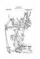
- Figure 1 is a front elevation of my improved machine.
- Fig. 2 is a top plan view of the same.
- Fig. 3 is an end elevation.
- Fig. 4% is a transverse section substantially on the line 4.4 of Fig. 2.
- Fig. 5 is a perspective view of the operating mechanism.
- Fig. 6. is an enlarged plan view of the gaging device illustrating the position of the parts with one form of'collar.
- Fig. 7 is a detail plan view of one side of the gaging device and illustrating the gage positioned for another.
- Fig. 8 is an end elevation of the gaging device.
- Fig. 9 is a detail perspective view of one of the "gages.
- Fig; 10 is a detail front view of the gaging device.
- Figs. 11 to 16 represent detail views ofthe operating cams.
- Fig. 17 is a detail view of one of the abutment stops.
- I 1 indicates a frame, on the base of which are mounted two button hole stitching machine heads A and of appropriate type.
- Each head includes: stitching mechanism 3;
- a longitudinal grooved bar or guide 18 on which slides the base bar 19 of a gaging device 20.
- the forward end of the base bar is formed with a transverse hollow head 21, provided on'top with a knob on handle 22, to form a hand grip.
- On top of the base bar 20 is a thin sheet of metal to form the central support of the gaging device, and to which are adjustably secured two flat thin strips, forming angular adjustable supports 24.
- Fitting in the hollow transverse head 21 are two superimposed flat bars25 to the outer opposite end of each respective bar is secured a thin metal plate 26 about in the same plane as the central "support 23, and forming end supports for block is formed with an enlarged portion provided with an opening through which a screw passes to clamp said block to its bar 29, and from the enlarged portion, and under the bar 29, extends a lip 31 having its inner end beveled to engage a collar, if it be one of substantially uniform width throughout, or the crotch between the body portion and a tab if the collar be of the tabtype, as shown in Figs. 6 and 7.
- a cover plate 32 is secured to the bar 29 and extends over the block 30, to form an uninterrupted path for the-collar being introduced.
- the transverse superimposed bars 25 are held in adjusted position by screws 33,- fitting in openings in the hollow head 21.
- the central and end plates 23 and 26, are so arranged as will permit of awiderange of adjustment, hence it follows theyare spaced apart, which makes itnecessary to provide the adjustable angular supports 24:.
- Each end support 26 is provided with a vertical end extension 35 formed with aslot 36 to receiveja rod 37held in adjusted position by a clamp nut 38,-;and
- these fingers provide means for preventihg the collar being inserted and the one **d to the stitching mechanisms, for it is important that the collar be as free as possible to enable the ready withdrawal of the gaging device from beneath the cloth clamps.
- the gaging device is limited in its rearward movement by an adjustable stop 40.
- This stop comprises a threaded rod 41, mounted to turn in a threaded opening. in a standard 42, and held in set position by a lock nut 43. "While it is true the rearward movement of the loader is limited by the stop 4-0, it is equally true that the rear edge of the collar must also be limited to insure a proper setting or gaging of the ends to properly locate the button hole with a fine degree of accuracy.
- each head A and B a gage stop, each of which consists of-a flatstrip 46 having its front end bent upwardly and forwardly to form an abuttingsi-irface 46 for the edges of "the collar, and an overhanging flange to overlap said collar.
- the inner end of each flat strip is slotted at 47, through which passes an adjusting screw 48, which engages a'threaded opening in a flat bar 49 fastened to the bed of each head.
- adjusting screw 48 By this construction-the flat strips 45, may be adjusted in any direction to accommodate the curvature or the angle of the edge of a collar.
- These gage stops are positioned so that about the time the gaging device contacts with the stop 40, the rear edge of the collar will. con-.
- brackets 50 secured to the front of the frame 1 are two brackets 50, in which is mounted a shaft 51 on one end of which is fastened a curved lever 52 and at its opposite end it is provided with a depending rod 53.
- This device is what I shall term-a trip, for a purpose to be described.
- a chain 54 which passes up over an idle pulleyj55, mounted on the grooved bar 18 and thenceextends for- Wardly under and around a second idle pulley 56, also mounted on the grooved bar 18 and is secured to the rear end of the gaging device.
- This lever and its connection in suitable bearings is a power shaft prowith the gaging device form very essential elements in the automatic operation of the machine for it is the movement of this lever through the medium of the gaging device, and the trip which permits of the automatic throwing into motion a cam shaft which connections automatically operate the cloth clampsand the stitching mechanisms and causes them to perform a cycle of movement.
- a cam shaft which connections automatically operate the cloth clampsand the stitching mechanisms and causes them to perform a cycle of movement.
- a rocking frame 65 Also pivotally mounted on the shaft 60, is a rocking frame 65, the inner end of which extends to about the center of the frame 1, and is provided with bearings.
- a worm gear 76 mounted on-the end of a cam shaft 79 extending across the frame 1 and mounted 1n suitable bearings.
- the worm gear, cam shaft, and its connections, constitute 'aux1liary powenrhechanism.
- a cam 52 On the cam shaft t0 automatically withdraw 140 is a cam 52, designed to cooperate with the lever 52, to depress it at the proper time the gaging device from the cloth clamp.
- On this cam shaft is secured a disk 80, provided with a cut away portion or seat8l, for the nose 82 of a belt shifting lever 88, pivoted at its lower end at 84. This lever it will be noted is released by the trip the nose 82 will, by gravity fall out of the seat 81.
- a rod 86 Extending forwardly from the lever 83, is a rod 86, having its end 87, bent inwardly to be engaged by the rod 53 of the trip. From a projection on the lever extends an adjustable rod 88. carrying at its outer end a bifurcated standard 89 to en gage the belt to shift the latter from the loose to the fast pulley at the proper time, and'vice versa.
- the movement of the lever 83 is such that the nose will recede from its seat sufficiently to permit the concentric portion of the disk to freely pass, so that the nose cannot again be seated until the disk'has made substantially one'revolution.
- the cam 52 is not in the path of'movement of the roller 52*, but the auxiliary power mechanism is in operation.
- cam shaft 79 On the cam shaft 79 are two cams 100 and moves up .levers of the stop motion devices of the respective heads A and B.
- the cams depress the levers 101, the rod engages the hooks of the links 105, and operates the stop motion devices and by shifting the power,
- the ,cam 80 is so timed that after the cams 90, and 100 have passed the rollers on the levers 91 and 101, the nose 82 of-the lever 83 will be drawn into the seat 81 by the depending rod 53 contacting with the inturned end 87 of the rod 86, a spring 110 attached to a projection on the shaft exerting the necessary force to perform this operation.
- gears and shaft 79 constituting the auxiliary power mechanism comes to a stop, but the main power mechanism continues to-loperate, so that all the operator has to do is to feed an article to the stitching mechanisms, in order to again complete another cycle of operation, which will begone into farther on in this description.
- Brackets 113 extend forwardly on the frame 1, to'support a bar 114 which lies just in advance of the hooked links 105.
- Each bracket forms a guide to limit the movement of the bar, and in the bottom of each guide are two depressions 115, in which the bar seats when in its forward or rearward position.
- Extending from the bar is a rod 116 which extends'throughto the front of the frame to be in convenient reach of the operator. If it be desired to operate the mechanism without the stitching mechanism, the rod is pushed rearwardly and the hooked links are removed from path of movement of the bar 104: as will bepresently explained.
- the shaft 66 has secured to it two grooved asses a' ulleys 120, and 121, around which elt 1.22 which as previously state consti- The cams 100,
- This belt is for. the purpose of driving the mechanism on the'heads A and B, and-the parts are so arranged as to accommodate the belt for any" adjustment of the said heads.
- Swiveled in two brackets extending up from the frame 1, are two pairs of pulleys indicated at 125, and 126.
- the belt 122 passes around the loose pulley 5, on the head B, thence around one of the pulleys 126 and over and around one of the pulleys 121, then down and around pulley 120 on the shaft 66.
- the belt then extends up and around one of the pulleys 123, and around one of the pulleys 125, and over the loose pulley 5, on the head A. From this loose pulley the belt passes around the lower pulley 125, one of the pulleys 123, and down and .around pulley 121 on shaft 66, and up and over pulley 121 and around one of the pulleys 124, and 126 to the loose pulley on head B.
- the entire power from shaft 66, to the sewing machine heads is imparted by a single belt, which insures of the mechanism being uniformly operated, and which will permit of all the necessary adjustment -of the parts without'in any way separately adjusting the belt.
- the weight of the yoke frame is quite sufficient to maintain the belt taut, and as said yoke frame is pivoted on the shaft 60, it will readily yield if an unusual strain should suddenly be placed on the belt.
- the power belt 130 is shifted from the fast to the loose pulleys on shaft 60, by'a belt shifter 131, pivotally mounted on the frame 1,'and provided with an arm 132,
- a link 133 extending forwardly to the front of the machine.
- the forward end of the link ispivoted to a lever 131, extending from a foot treadle 1355, located in convenient reach of .the operator.
- end supports 2G26 of the gaging device are laterally adjusted and the gages 2828 are set to accommodate the particular style of collar to be operated upon.
- the adjust able supports 24: are also adjusted to support the collar between the end supporting plates and the central supporting plates.
- the two heads A and B are adjusted.both laterally and radially to accommodate the shape of the collar, and the disposition of the buttonhole therein and the gage stops 46 must also be set.
- the treadle 135 is now-rocked and the power belt is shifted to the fast pulley '61, and motion is imparted to the belts 75 and 122.
- the operator holds the gagingv device with the collar stationary so that immediately the clamps are lifted, with a quick motion, the gaging device is pushed farther up against the stop 40, and the rear edge of the collar up against the abutting surfaces 46, of the gage stops, with the ends under said clamps.
- This movement as before stated brings the roller 52* up into the path of movement of the cam 52.
- the cams 90 are timed so as to only hold the clamp elevated for sufficient time to allow the operator to place the gaged collar under them, then the clamps are lowered and hold the collar on the supports momentarily, for in a moment thereafter, the cam 52, acts on the lever 52 and, depresses it thereby withdrawing the gaging device from beneath the clamps.
- the cam shaft is geared to the main power mechanism so that a complete revolution of said cam shaft is made, before the stitching operation is completed.
- the cam shaft completes its revolution in about 2; to of the time that it takes to complete a button hole by the stitching operation.
- This relative movement of the parts is for the purpose of placing the mechanism in restarting position, and to avoid the necessity of accurate timing of the parts.
- the gaging device with its collar must not op- The operator moves the lever 16 on the head where the stitching is to be mended and starts the stitching mechanism and thereby effects-the stitching operation. If, however, the operator fails to notice the defeet until after the collar is withdrawn, it must again be placed on the gaging device and reintroduced under the clamps as pre viously described. But to avoid the automatic starting of the two stitching mecha- 'nisms the rod 116, is forced inwardly to push the hook links 105 from the path of movement of the cross bar 114:.
- the various'cams are timed to permit sufficient time for the operator to manipulate thecollar to accomplish'the desired results, and to insure of the Various operations being performed in their proper sequence.
- the improvement willje'xpedite the manu-. facture of buttonholes in collars and cuffs, and by reason of the automatic operation of the respective parts,unskilled help maybe employed, and less physical efiort is required to effect the operation.
- the treadle 135 may be depressed at its front end at any stage of the operation to shift the power belt 130,
- the gaging device is mounted to slide as freelyas possible on the bar 18, and to reduce the friction balls 18 and means for automatically withdrawing the gaging device prior to the operation of the stitching mechanism.
- the combination of stitching mechanism, auto- 'matic mechanism for starting the stitching mechanism, power mechanism and movable means including an artlcle gaging devlcefor ,starting the power mechanism to operate the stitching mechanism, said means being arranged to cease its movement before the automatic mechanism is. operated to stop the stitching mechanism.
- the combination of stitching mechanism, power mechanism including a shiftable belt, a shaft, a movable gaging device, means between the shaft and the gaging. device to cause the shifting of the belt to operate the shaft and start the stitching mechanism, and means for automatically withdrawing the movable gaging device prior to the operation of the stitching mechanism.
- the combination of two button hole machine heads each of which includes stitching mechanism, a cloth clamp, and automatic starting and stopping means, a slidable gaging device operable toward and from the heads, end gages mounted on the gaging device, power mechanism for operating the stitching mechanisms and cloth clamps, and means controlled by the movement of the gaging device for starting the power mecha-' nism.
- buttons in a button hole machine, the combination of two button hole stitching machine heads, each of said heads including independent stitching mechanism, a cloth clamp,
- a gaging device for positioning an article to the stitching mechanism, and a connection between the gaging device and the auxiliary power mechanism, whereby when the gaging device is operated the main power mechanism will operate the auxiliary power mechanism to lift the clamp and operate the stitching mechanism.
- a movable gaging device including gages, stationary stops adjacent the stitching mechanisms, the gages ou the movable gaging device and the stops cooperating to position an article to be operated upon, connections between the cloth clamps and the stitching mechanisms-andthe power mechanism, means controlled by the movement of the movable gaging device for causing the power mechanism 'to lift the cloth clamps and start the stitching mechanisms, and means forstopping the movement of' the parts of the power mechanism .
- the stitching mechanisms, and tripping mechanism connected with the slidable gag ing device for throwing said shaft into operation.
- a cloth clamp mechanism for. causing the cloth clamp to raise and the'stitching mechanism to complete a cycle of movement
- a slidably mounted gaging device means'betwe'en the slidably mounted gaging device and the cloth clamp to cause the latter to be ele vated before thestarting of the cycle of movement of the stitching mechanism, and means for automatically withdrawing the slidably mounted gaging device after the as i cloth clamp is lowered and before the stitch ing operation is started.
- a slidably mounted gaging device operable toward and from the stitching'mechanism, means for automatically lifting the cloth clamp by the movement of the 1slidably mounted gaging device, means for automati cally lowering the cloth clamp, automatic means for withdrawing the vslidably mounted gaging device from beneath the clamp after the latter has been lowered, and means for stopping the stitching operation without stopping the mechanism which operated the stitching mechanism.
- a gaging device operable toward and from the stitching mechanisms, a shifter, trigger mechanism forholding the shifter in normal position, a connection between the trigger mechanism and the gaging device,
- the trigger mechanism being operated upon by the cam to permit the shifter to operate to stop the auxiliary power mechanism.
- a slidable gaging device including ages, a timing dislrhavinga seat and mounted on the shaft, a leverv cooperating with the-seat in the timing disk to stop the'shaft,-.a connection between the gaging device and the lever which co6perates with the timing disk, said connection being operated upon by one of the cams to automatically withdraw the gaging-device from under the cloth clamps, means for automatically causing the timing lever to drop ,into its seat, andpower means for operating the shaft.
- the gaging device for causing the main power mechanism to operate the auxiliary power mechanism,'and means 01 .nrablc by the auxiliary power mechanism for automatically disconnecting the auxiliary power mechanism from the main power mechanism.
- the combi-- nation of stitching mechanlsm including a power shaftand fast and *ioosepulleys, a stop motion device, and a cloth clamp, main power mechanism, auxiliary power mecha nism operable by the main power mechanism, means between the auxiliary power mechanism and the stop motion device to operate the latter to start the stitching operation,-means between the auxiliary power mechanism and the cloth clamp to automatio ally elevate the latter, a belt included in the main power mechanism cooperating with either the fast or the loose pulley of the stitching mechanism, a movable gaging device including gages, means controlled by the gaging, device for connecting the main power mechanism with the auxiliary power mechanism, means cooperating therewith for automatically withdrawing the gaging device after thecloth clamp has been lowered, means for automatically disconnecting the auxiliary power mechanism before the belt is shifted by the stopmotion device to stop the stitching operation, manual means for disconnecting. the means between the stopmotion device and the auxiliary power mechanism without interfering wit 1
- a stop motion device constantly operating main power mechanism including a belt, auxiliary power mechanism .including a. fast pulley adapted to receive the belt of the continually operating power mechanism, a disk formed with a seat, a belt shifter cooperating with the belt and the disk, cams ope 'ated by the auxiliary power mechanism for operating the stop motion to start the stitching operation and for elevating the cloth clamps, a slidably mounted gaging device including-gages, tripping mechanism for holding the belt shifterin the seat of the disk, a-fiexible connection between the gaging device and the tripping device whereby when the gaging device is forced up to the stitching mechanism the belt shifter will be operated to cause the belt to operate the auxiliary power mechanism, a cam for operating on the tripping device for automatically withdrawing the gaging "device from under 'the cloth clamp, and means holding the tripping device and belt shifter under tension to retain the belt shifter adjacent the periphery of the disk and readyto fall into the seat after the withdrawal of the
- auxiliary power mechanism including a shaft operable by the continually operating power mechanism, means between the shaft and the cloth clamps for automatically elevating the same, connections between the shaft and the stop motion devices including cams and connected levers and hooked links suspended fromthe said stop motion devices and located in the path of movement of the connection between the 4 levers, manual means for removing the hooked links from ,the path of movement of' Ill-6 power mechanism to operate the auxiliary power mechanism.
- auxiliary power mech-' anism including a shaft operable by the continually operating power mechanism, connections between the shaft and thecloth clamps including connected levers, cams and links cooperating with the levers and said cloth clamps, connectionsbetween the shaft and the stop motion devices including cams and connected levers and hooked linkssuspended from the said stop motion devices and located in the path of movement of the connection between the levers, manual means for removing the hooked links from the path of movement of the connections between said levers, a gaging device, and means controlled by the inward movement of the gaging device for causing the main power mechanism to operate the auxiliary power mechanism including means for automatically stopping the auxiliary power mechanism.
- connection between the auxiliary power mechanism and the cloth clamp to elevate the latter means controlled by the gaging devicefor connecting the auxiliary power mechanism with the main power mechanism, a cam o aerated by the auxiliary power mechanism or'enga'ging the latter connectingmeans to automati 'cally withdraw the gaging device after the cloth clamp has lowered, and automatic means for disconnecting the auxiliary power mechanism before the stitching mechanism stops its operation.
- a button holemachine the combination of stitching mechanism, a cloth clamp, a stop motion device,. a slidably mounted gaging device including gages, main power mechanism, auxiliary power mechanism, a
- connection between the auxiliary power mechanism and the cloth clamp to elevate the latter a connection between the stop motion device and the auxiliary power mechanism to shift the stop motion device to start the stitching mechanism
- means vcontrolled by the gaging device for cphnecting the auxiliary power mechanism with the main power mechanism a cam operated by the auxiliary power mechanism for engaging the latter connecting means to,-automatically withdraw the gaging devices aftr the cloth clamp has lowered
- automatic means for disconnecting the auxiliary power mechanism before the stitching mechanism stops its operation manually operated means for d1sconnecting the connection between the stop motion device and the auxiliary powermechanism, and manual means for operating the stop motion device without operating the auxiliary power mechanism.
- slidably mounted gaging device adaptedto deliver'work under the 'work clamp when 'same is elevated, power mechanism, means operated by the slidably mounted gaging devicefor starting'the stitching mechanism" and elevating the work clamp, means for automatically lowering the work clamp,
- a gaging device power mechanism, means operated by thepower mechanism for ele- 'vating'the Workvclamp, means for auto matically lowering the work clamp, means operated by the power mechanism for withdrawing the gaging device after the work I clamp is lowered and the work is held in position for receiving the stitches, and means for stopping the power mec'hanisin after the stitching mechanism has operated 7 and before the work clamp has been elevated.
- auxiliary 'power mechanism means operated by the gaging device to cause the main power mechanism to operate the auxiliary power mechanism upon each movement of the gaging device toward the 'stiching mechanism, means operated by the auxiliary power mechanism for elevating the clamps,
- auxiliary power a stop motion device means for withdrawing the gagingv device from the cloth clamps, means forautomatically disconnecting the auxiliary power a stop motion device, main power mechanism, auxiliarv powerniechanism, a gaging device means operated by the gaging-device for causing the main power mechanism to operate the auxiliary power mechanism, a connection between the auxiliary power mechanism and the. cloth clamp to elevate, the latter, a ,connection between the aux 1 iliary power mechanism and the stop motion device to cause the main power mechanism to operate the stitching mechanism,
- the combination of two stitching mechanisms a gage associated with 'eachstitching mechanism, a slidably mounted gaging device including gages which cooperate with the gages associated with the stitching mechanisms, means for limiting the movement of the gaging devicewhen the work is gaged,'cloth clamps for the stitching'mechanisms, main power mechanism, auxiliary power .iechanism, means controlled by the movement of the gagingdevice for-causing the main power mechanism to operate theauxiliary power mechanism to elevate the cloth clamps to permit subsequent movement of the gaging mechanism including means for permitting of the lowering of the cloth clamps, and means for Withdrawing the vgaging device independently of the work, subsequently operating the stitching mechanism, and automatic means independent of the auxiliary power mechanism for stopping the stitching mechanisms.
- the auxiliary power mechanism including means for permitting of the lowering of the cloth clamps
- the tripping means, gaging device and cloth clamp being arranged so that the gaging device in its movement tointroduce the work V must be'stopped between the'starting of the power mechanism and the lifting of the clamp, and subsequently moved again in its first direction to introduce the work undersaid cloth clamp, and means for automati cally vithdrawing'the gaging device from the clamp independentof the work, after the clamp is lowered;
- stitching mechanism In a button-hole machine, stitching mechanism, power mechanism therefor, control devices intermediate said power mechanism and stitching mechanism, auxiliary power mechanism for operating the control' devices, and a gaging device governing the operation of the auxiliary power mechanism.
- stitching mechanism In a buttonhole machine, stitching mechanism, a manually operated-gaging device movable to and from the stitching mechanism, power mechanism, and stitchingmechanism control-devices normally held from the influence of the power mechanism said gaging device controlling said stitching mechanism controlled devices.
- stitching T mechanism normally operative p means, control devices intermediate power. means and stitching i'uechanisi'n starting the latter, said'control devices being normally inoperative, and mechanism oper ated directly by thepower means for timedeterminate for the governing of "tlfi col..--
- gaging device including gages to gage an article tobe operated upon, a guide for said gaging device, manually operated means for positioning said gaging device and the article to be operated upon by the stitching mechanism, and means to cause said gaging device to be withdrawn from gaging position before the stitching mechanism commences to operate.
Landscapes
- Engineering & Computer Science (AREA)
- Textile Engineering (AREA)
- Sewing Machines And Sewing (AREA)
Description
H. c. MILLER. BUTTONHOLE MACHINE, APPLICATION FILED AUG. I6, 19!].
Patented J an. 4, 1916.
6SHEETS-SHEET 1.
Show x 501,
,H. c. MILLER. BUTTONHOLE MACHINE,
, VAPPLVICATIQN Fl LED AUG.I6. I911. I 136K197, Patented Jan.4,1916- H. c. MILLER.
BUTTONHOLE MACHINE APPLICATION FILED AUG. I6, I91].
Patented Jail. 4, 1916) 6 SEETS-SHEET 4.
In rental. A4 Chilly/Z131.
H. C. MiLLER- BUTTONHOLE MACHINE, APPLICATIDN FILED AUG: 16, 1911.
Patented 5511A, 1916.
6 SHEETS-SHEET 5.
H. VCQMILLER.
.BUTTONHOLE MACHINE, APPLlCATlON FILED AUG. 16. 1911.
1,167,197 I i Patented Jan. 4, 1916.
6 SHEETS-SHEET 6.,
HENRY G. MILLER, OF WATERFORD, NEW YORK.
BUTTONHOLE-MACHIN E.
Specification of Letters Patent.
mama Jan. 4, 1916.
Application filed August 16, 1911. Serial No. 6%,444;
To all whom it may concern: I
Be it known that I, HENRY C. MILLER, a citizen of the United States, residing at Waterford, in the county of Saratoga and State of New York, have invented certain new and useful Improvementsin Buttonhole-Machines; and I do hereby declare the following to be a full, clear, and exact. description of the invention, such as will enable others skilled in the art to which it appertains to make and use the same, reference being had to the accompanying drawings, and to letters or figures of reference marked thereon, which form a part of this specification.
This invention relates to improvements in button hole machines, and primarily to one known in the art as a double header.
Prior to my. presentfimprovements it was customary to arrange the mechanism in such manner that the operator in one instance in order to complete acycle of movement was compelled to operate a 'treadle or similar means, or the mechanism was under control, and could be stopped and started within a given cycle of movement. Ineach instance,
-. however the o erator was com oelled to start the mechanism for each cycle of movement by manipulating separate starting means,
although such movement was automatically stopped when the stitching operation was completed. Necessarily, as in'making button holes, the labor involved in this frequent starting of the machine soon tired the operator. Furthermore, the starting devices of all sewing machines of the type referred to, are in each instance connected directly to parts of the-operating mechanism which requires extraordinary force to'efiect their throwing into action consequently requiring laborious work, .as above stated.
' According to my invention, I propose to overcome the noted objections, as well as many others, by providing specially designed main power operating means, and
auxiliaryopower operating means associated with the stitching mechanism, so that when the operator feeds a collar to the stitching mechanism, the stitching, clamping, trimming, and cutting blade will automatically continue to operate in sequence. The stitching operation-may be stopped and is under perfect control at any time in any one of its definite cycles of movement. This arrangement of parts obviates the necessity of the' laborious work of operating separate starting mechanism at the beginning of each cycle of movement, and because of the many automatic features involved, permits of the employment of less stronger help than with other machines. A further object of this invention is to provide improved means for gaging the article to receive the button holes, and. so connecting the gaging means that'it controls the setting into motion of the means for automatically making the button holes, and
the means for automatically removing the gaging means from the cloth clamps.
This invention also involves improvements in the specific details of construction and arrangement of parts, which will be hereafter described, ed out in the claims.
Inthedrawings, forming a part of this specification: Figure 1 is a front elevation of my improved machine. Fig. 2 is a top plan view of the same. Fig. 3 is an end elevation. Fig. 4% is a transverse section substantially on the line 4.4 of Fig. 2. Fig. 5 is a perspective view of the operating mechanism. Fig. 6.is an enlarged plan view of the gaging device illustrating the position of the parts with one form of'collar. Fig. 7 is a detail plan view of one side of the gaging device and illustrating the gage positioned for another. Fig. 8 is an end elevation of the gaging device. Fig. 9 is a detail perspective view of one of the "gages. Fig; 10 is a detail front view of the gaging device. Figs. 11 to 16 represent detail views ofthe operating cams. Fig. 17 is a detail view of one of the abutment stops.
I 1 indicates a frame, on the base of which are mounted two button hole stitching machine heads A and of appropriate type. Each head includes: stitching mechanism 3;
,fast pulley 4; loose pulley 5; stop motion and particularly pointwith an independent hand starter for starting the stitching mechanism without starting the similar mechanism on the companion head. {This device involves a lever 16 located in convenient reach of the oper -ator.and is connected to the stop motion de similar to-those disclosed in my prior Patvice, whereby if it be desired to mend a button hole it may be accomplished without throwing into operation all the mechanism about. to be described. These features are ent No. 810,297, dated Jan. 16, 1906, in view offwhich it is not deemed essential to specifically describe them.
Preferably disposed between the two heads A and B, is a longitudinal grooved bar or guide 18 on which slides the base bar 19 of a gaging device 20. The forward end of the base bar is formed with a transverse hollow head 21, provided on'top with a knob on handle 22, to form a hand grip. On top of the base bar 20 is a thin sheet of metal to form the central support of the gaging device, and to which are adjustably secured two flat thin strips, forming angular adjustable supports 24. Fitting in the hollow transverse head 21 are two superimposed flat bars25 to the outer opposite end of each respective bar is secured a thin metal plate 26 about in the same plane as the central "support 23, and forming end supports for block is formed with an enlarged portion provided with an opening through which a screw passes to clamp said block to its bar 29, and from the enlarged portion, and under the bar 29, extends a lip 31 having its inner end beveled to engage a collar, if it be one of substantially uniform width throughout, or the crotch between the body portion and a tab if the collar be of the tabtype, as shown in Figs. 6 and 7. A cover plate 32, is secured to the bar 29 and extends over the block 30, to form an uninterrupted path for the-collar being introduced. The transverse superimposed bars 25 are held in adjusted position by screws 33,- fitting in openings in the hollow head 21.
The central and end plates 23 and 26, are so arranged as will permit of awiderange of adjustment, hence it follows theyare spaced apart, which makes itnecessary to provide the adjustable angular supports 24:. For
when the end plates are adjusted and to properly support the collar the supports 26,
must also be adjusted. Each end support 26 is provided with a vertical end extension 35 formed with aslot 36 to receiveja rod 37held in adjusted position by a clamp nut 38,-;and
merger provided on its inner end with a down wardly and rearwardly curved finger 39.
'These fingers are located adjacent the gages 28' and extend in close proximity to the end supporting plates 26 and are designed to prevent'the ends of the collar turning up,
and they also afi'ord means for assisting in the withdrawal of: a collar from the heads. Further these fingers provide means for preventihg the collar being inserted and the one duced to the stitching mechanisms, for it is important that the collar be as free as possible to enable the ready withdrawal of the gaging device from beneath the cloth clamps.
The gaging device is limited in its rearward movement by an adjustable stop 40. This stop comprises a threaded rod 41, mounted to turn in a threaded opening. in a standard 42, and held in set position by a lock nut 43. "While it is true the rearward movement of the loader is limited by the stop 4-0, it is equally true that the rear edge of the collar must also be limited to insure a proper setting or gaging of the ends to properly locate the button hole with a fine degree of accuracy. I have therefore provided on the bed plate of each head A and B, a gage stop, each of which consists of-a flatstrip 46 having its front end bent upwardly and forwardly to form an abuttingsi-irface 46 for the edges of "the collar, and an overhanging flange to overlap said collar. The inner end of each flat strip is slotted at 47, through which passes an adjusting screw 48, which engages a'threaded opening in a flat bar 49 fastened to the bed of each head. By this construction-the flat strips 45, may be adjusted in any direction to accommodate the curvature or the angle of the edge of a collar. These gage stops are positioned so that about the time the gaging device contacts with the stop 40, the rear edge of the collar will. con-.
tact with the abutting surfaces 46", and the collar will be properly located under the cloth clamps at the time the gaging device ceases its movement.
secured to the front of the frame 1 are two brackets 50, in which is mounted a shaft 51 on one end of which is fastened a curved lever 52 and at its opposite end it is provided with a depending rod 53. This device is what I shall term-a trip, for a purpose to be described. To the free end of the curved lever 52 is adjustably secureda chain 54 which passes up over an idle pulleyj55, mounted on the grooved bar 18 and thenceextends for- Wardly under and around a second idle pulley 56, also mounted on the grooved bar 18 and is secured to the rear end of the gaging device. This lever and its connection in suitable bearings is a power shaft prowith the gaging device form very essential elements in the automatic operation of the machine for it is the movement of this lever through the medium of the gaging device, and the trip which permits of the automatic throwing into motion a cam shaft which connections automatically operate the cloth clampsand the stitching mechanisms and causes them to perform a cycle of movement. On one side of the frame 1 and mounted vided with fast and loose band pulley 61 and 62. At one end of this shaft is fastened aband pulley 63, and at its opposite end is a band pulley 64. Also pivotally mounted on the shaft 60, is a rocking frame 65, the inner end of which extends to about the center of the frame 1, and is provided with bearings.
which receive a shaft 66, carrying a band pulley 67, around which and the band pulley 64 extends a belt (38. on the opposite side of the frame 1 is a shaft 69 on which is a worm 70, and fast and loose slightly grooved pulleys'71. and 72, and normally extending around the grooved pulley 63, on shaft 60,
and the loose pulley 72, is a belt 75. This mechanism together with the belt 122 to: be referred to hereafter constitutes what I shall term the continually operating main power mechanism, i
Meshing with the worm 70 is a worm gear 76 mounted on-the end of a cam shaft 79 extending across the frame 1 and mounted 1n suitable bearings. The worm gear, cam shaft, and its connections, constitute 'aux1liary powenrhechanism. On the cam shaft t0 automatically withdraw 140 is a cam 52, designed to cooperate with the lever 52, to depress it at the proper time the gaging device from the cloth clamp. On this cam shaft is secured a disk 80, provided with a cut away portion or seat8l, for the nose 82 of a belt shifting lever 88, pivoted at its lower end at 84. This lever it will be noted is released by the trip the nose 82 will, by gravity fall out of the seat 81. Extending forwardly from the lever 83, is a rod 86, having its end 87, bent inwardly to be engaged by the rod 53 of the trip. From a projection on the lever extends an adjustable rod 88. carrying at its outer end a bifurcated standard 89 to en gage the belt to shift the latter from the loose to the fast pulley at the proper time, and'vice versa.
When the gaging device is pushed rearinclines, so that when it ward tointroduce a collar, or other articleto the heads A and B, and just before reaching the cloth clamps, the slack in the chain 54 is taken up Which rerlzs the lever 52,and
, brings its roller 52* adjacent the path of movement of the cam 52*. -This movement also rocks the shaft 51, and removes the depending rod 53,, from the inturned end 87, ,of the rod 53, and permits the lever 83 to fall from the seat 81 in the cam disk. lVhen this occurs the belt shifter 89, shifts the belt 75from the loose to the fast pulley 71, and as the belt 75 is constantly in motion, motion will, through the worm gear, be imparted to the cam shaft '79, hence the main power mechanism operates the auxiliary power mechanism. The movement of the lever 83, is such that the nose will recede from its seat sufficiently to permit the concentric portion of the disk to freely pass, so that the nose cannot again be seated until the disk'has made substantially one'revolution. At this time however the cam 52 is not in the path of'movement of the roller 52*, but the auxiliary power mechanism is in operation.
Near opposite ends of the cam shaft ,79, v
are cams 90, so timed that soon after the cam shaft starts to revolve, levers 91 will be depressed to lift the cloth clamps. Each lever 91 is pivoted at 92 and beyond the pivot point is a spring 93 to return the parts to normal position. The opposite end of said and in position to receive the button holes. a When the gaging device is given its final movement the roller 52 is brought into the path of movement'of the cam 52 so as to depress the lever 52 at the proper time. The gaging device having positioned the'collar under the cloth clamps,.the latter are lowered by the usual springs 98, and the collar is momentarily clamped between said cloth clamps, and the end supports 26 of the gaging device. I The clamps now having positioned the collar, the cam 52' contacts with the roller 52 on the lever 52 andrdepresses it, which pulls on the chain 54, and automatically withdraws the ends of the gaging device from under the clamps, the springs 98 causing the latter to hold the collar in position to be operated upon. Immediately the gagingdevice is withdrawn, the stitching, cutting and trimming operations are performed in their-respective order by the following mechanism;
On the cam shaft 79 are two cams 100 and moves up .levers of the stop motion devices of the respective heads A and B. When the cams depress the levers 101, the rod engages the hooks of the links 105, and operates the stop motion devices and by shifting the power,
matically thrown in and the mechanisms' will cease their respectlve operations with the collar still he ldby the cloth clamps. The ,cam 80, is so timed that after the cams 90, and 100 have passed the rollers on the levers 91 and 101, the nose 82 of-the lever 83 will be drawn into the seat 81 by the depending rod 53 contacting with the inturned end 87 of the rod 86, a spring 110 attached to a projection on the shaft exerting the necessary force to perform this operation.
It may be stated at this time that when the trip was operated by the gaging device to disengage the lever 83 from the disk 80,
@that the nose 82 moves far enough away from the disk 80, so that when the gaging device is returned to normal position the end of the nose will be held against the periphery of disk 80, ready to be dropped into the seat 81 by the spring 110. When the lever 83, is returned to its normal position it shifts the belt 75, from the fast to the loose pulley 72,so that the camshaft,
gears and shaft 79 constituting the auxiliary power mechanism, comes to a stop, but the main power mechanism continues to-loperate, so that all the operator has to do is to feed an article to the stitching mechanisms, in order to again complete another cycle of operation, which will begone into farther on in this description.
Two brackets 113, extend forwardly on the frame 1, to'support a bar 114 which lies just in advance of the hooked links 105. Each bracket forms a guide to limit the movement of the bar, and in the bottom of each guide are two depressions 115, in which the bar seats when in its forward or rearward position. Extending from the bar is a rod 116 which extends'throughto the front of the frame to be in convenient reach of the operator. If it be desired to operate the mechanism without the stitching mechanism, the rod is pushed rearwardly and the hooked links are removed from path of movement of the bar 104: as will bepresently explained.
The shaft 66 has secured to it two grooved asses a' ulleys 120, and 121, around which elt 1.22 which as previously state consti- The cams 100,
tutes' a part of the main power mechanism. This belt is for. the purpose of driving the mechanism on the'heads A and B, and-the parts are so arranged as to accommodate the belt for any" adjustment of the said heads. Swiveled in two brackets extending up from the frame 1, are two pairs of pulleys indicated at 125, and 126.
The belt 122, passes around the loose pulley 5, on the head B, thence around one of the pulleys 126 and over and around one of the pulleys 121, then down and around pulley 120 on the shaft 66. The belt then extends up and around one of the pulleys 123, and around one of the pulleys 125, and over the loose pulley 5, on the head A. From this loose pulley the belt passes around the lower pulley 125, one of the pulleys 123, and down and .around pulley 121 on shaft 66, and up and over pulley 121 and around one of the pulleys 124, and 126 to the loose pulley on head B. By this arrangement, the entire power from shaft 66, to the sewing machine heads is imparted by a single belt, which insures of the mechanism being uniformly operated, and which will permit of all the necessary adjustment -of the parts without'in any way separately adjusting the belt. The weight of the yoke frame is quite sufficient to maintain the belt taut, and as said yoke frame is pivoted on the shaft 60, it will readily yield if an unusual strain should suddenly be placed on the belt.
The power belt 130, is shifted from the fast to the loose pulleys on shaft 60, by'a belt shifter 131, pivotally mounted on the frame 1,'and provided with an arm 132,
to which is pivoted a link 133, extending forwardly to the front of the machine. The forward end of the link ispivoted to a lever 131, extending from a foot treadle 1355, located in convenient reach of .the operator.
In operating my improved machine, the
end supports 2G26 of the gaging device are laterally adjusted and the gages 2828 are set to accommodate the particular style of collar to be operated upon. The adjust able supports 24:, are also adjusted to support the collar between the end supporting plates and the central supporting plates. The two heads A and B, are adjusted.both laterally and radially to accommodate the shape of the collar, and the disposition of the buttonhole therein and the gage stops 46 must also be set. The treadle 135 is now-rocked and the power belt is shifted to the fast pulley '61, and motion is imparted to the belts 75 and 122. The operator now places acollar on the gaging device and forces the latter in toward the heads A and B, and just before the ends of the supports 2626 reach the cloth clamps the slack in the chain is taken up and the lever 52, is pulled up to bring its 1 roller adjacent the cam 52. This movement causes the dependingarm 53, to swing away from the inturned end of the rod 86 which permits the lever 88, to swing by gravity and disengage the nose 82 from the cam 80, and shifts the belt to the fast pulley 71. Motion is now imparted to the cam shaft 79, and the cams 90 will operate on the levers 91, and raise the cloth clamps. During this time the operator holds the gagingv device with the collar stationary so that immediately the clamps are lifted, with a quick motion, the gaging device is pushed farther up against the stop 40, and the rear edge of the collar up against the abutting surfaces 46, of the gage stops, with the ends under said clamps. This movement as before stated brings the roller 52* up into the path of movement of the cam 52. The cams 90 are timed so as to only hold the clamp elevated for sufficient time to allow the operator to place the gaged collar under them, then the clamps are lowered and hold the collar on the supports momentarily, for in a moment thereafter, the cam 52, acts on the lever 52 and, depresses it thereby withdrawing the gaging device from beneath the clamps. This movement is only sufficient to withdraw the ends of the supportsbeyond the clamps, and the operator by pulling on the handle grip 22, returns the gaging device to its normal position to receive another collar. The cloth-clamps now hold the collar in position on the heads A and B, and the cams 100, operate on the levers 101 and pull the hook links 105, down and operate the stop motion device, to start the stitching operation. As previously stated the means operating the stitching mechanism automatically throws into operation the cutting blade and the trimmer,it being understood that the cutting blade may be of the type to be op erated before or after the formation of the stitches. The button holes having been completed the stop motion devices automatically stop the stitching mechanism.
The cam shaft is geared to the main power mechanism so that a complete revolution of said cam shaft is made, before the stitching operation is completed. In other words the cam shaft completes its revolution in about 2; to of the time that it takes to complete a button hole by the stitching operation. This relative movement of the parts is for the purpose of placing the mechanism in restarting position, and to avoid the necessity of accurate timing of the parts. After the stitching of the first collar is completed, another one having been placed on the gaging device, the latter is pushed in as before described. By so doing the cam shaft is again revolved, hence the cloth clamps will be elevated and the operator quickly withdraws the completed collar and forces the gagingdevice toward the heads, and introduces the secured collar tov receive button holes in the same manner h'ereinbefore stated. In reerate.
desired to mend it, she may do so without lifting the cloth clamps. In this case the gaging device with its collar must not op- The operator moves the lever 16 on the head where the stitching is to be mended and starts the stitching mechanism and thereby effects-the stitching operation. If, however, the operator fails to notice the defeet until after the collar is withdrawn, it must again be placed on the gaging device and reintroduced under the clamps as pre viously described. But to avoid the automatic starting of the two stitching mecha- 'nisms the rod 116, is forced inwardly to push the hook links 105 from the path of movement of the cross bar 114:. Hence, while the cam shaft makes a complete revolution, the clamps will alone be liftedand the gaging device will be automatically removed from under the same as described. Now that the defective collar is clamped, theoperator will throw the lever 16, of the respective head and operate the stitching mechanism of this particular head and mend the button hole then the rod 116 is again withdrawn when the operation may be continued I as before.
From the foregoing description it will be seen that I have provided mechanism for forming a continuous cycle of operations, controlled by the introduction of the article being operated upon, and one in which the laborious work of throwing in the power separately, and then introducing a collar is dispensed with. Furthermore by the arerations in the cycleof movement are effected by the cams'on the power shaft, and
so long as the operator will feed a collar on the gaging device, or by the movement of the latter without a collar, the cycle of operation will occur without further'effort on the part of the attendant. "Yet the mechanism is so arranged that any particular fea-' ture of the cycle ofmovement is under the control of the operator.
The various'cams are timed to permit sufficient time for the operator to manipulate thecollar to accomplish'the desired results, and to insure of the Various operations being performed in their proper sequence.
' The improvement willje'xpedite the manu-. facture of buttonholes in collars and cuffs, and by reason of the automatic operation of the respective parts,unskilled help maybe employed, and less physical efiort is required to effect the operation. The treadle 135 may be depressed at its front end at any stage of the operation to shift the power belt 130,
which obviously throws out of operation the entire mechanism. While I have shown and described my invention for the purpose of making button holes in both ends of a collar, it will be obvious to one skilled in the art that the improvement is applicable to a single button hole machine, and I desire to reserve this right. The gaging device is mounted to slide as freelyas possible on the bar 18, and to reduce the friction balls 18 and means for automatically withdrawing the gaging device prior to the operation of the stitching mechanism.
2. In a machine ofthe. class described, the combination of stitching mechanism, auto- 'matic mechanism for starting the stitching mechanism, power mechanism and movable means including an artlcle gaging devlcefor ,starting the power mechanism to operate the stitching mechanism, said means being arranged to cease its movement before the automatic mechanism is. operated to stop the stitching mechanism. 3. In a machine of the class described, the combination of stitching mechanism, power mechanism including a shiftable belt, a shaft, a movable gaging device, means between the shaft and the gaging. device to cause the shifting of the belt to operate the shaft and start the stitching mechanism, and means for automatically withdrawing the movable gaging device prior to the operation of the stitching mechanism.
4c. In a machine of the class described, the combination of two button hole machine heads, each of which includes stitching mechanism, a cloth clamp, and automatic starting and stopping means, a slidable gaging device operable toward and from the heads, end gages mounted on the gaging device, power mechanism for operating the stitching mechanisms and cloth clamps, and means controlled by the movement of the gaging device for starting the power mecha-' nism.
5. In a button hole machine, the combination of two button hole stitching machine heads, each of said heads including independent stitching mechanism, a cloth clamp,
and a stop motion device, power mechanism,
connections between the v power mechanism. and the cloth clamps and the stop m ot-1on de- Llamas stitching mechanisms.
6. In a button-hole machine, the combination of stitching -mechanism and a cloth:
clamp, constantly operating main power mechanism, auxiliary power mechanism, connections'between the latter mechanism and the cloth clamp, and the stitching mechanism, a gaging device for positioning an article to the stitching mechanism, and a connection between the gaging device and the auxiliary power mechanism, whereby when the gaging device is operated the main power mechanism will operate the auxiliary power mechanism to lift the clamp and operate the stitching mechanism.
7. In a button hole machine the combination of stitching mechanism, a cloth clamp, a stop motion device, fast and loose pulleys, main power mechanism, auxiliary power mechanism connections between the auxiliary power mechanism and the cloth clamp and the stop motion device, a gaging device for positioning an article to the stitching mechanism, means between the gaging device and the auxiliary power mechanism for connecting the main and auxiliary power mechanisms, when said gaging device is operated, whereby to lift the cloth clamp and r the movement of the movable gaging device for causing the power'mechanism to lift the. cloth clamp and start the stitching m'echa nism. r
9. In abutton hole machine, the COIIlblIlfl:
' operate the stitching mechanism, and means tion of stitching mechanisms, cloth clamps,
power mechanism, a movable gaging device including gages, stationary stops adjacent the stitching mechanisms, the gages ou the movable gaging device and the stops cooperating to position an article to be operated upon, connections between the cloth clamps and the stitching mechanisms-andthe power mechanism, means controlled by the movement of the movable gaging device for causing the power mechanism 'to lift the cloth clamps and start the stitching mechanisms, and means forstopping the movement of' the parts of the power mechanism .the stitching mechanisms, and tripping mechanism connected with the slidable gag ing device for throwing said shaft into operation. 1
11.. In a button hole machine, the combination of stitching mechanisms, stop motion devices, cloth clamps, power mechanism, connections between the power mechanism and the cloth clamps to elevate the same and to the stop motion devices to shift the stop motion devices to cause the stitching mechanisms to operate, a slidably mounted gaging device including gages, means controlled by the slidably mounted gaging device for throwing into operation the power mechanism, automaticmeans operated by the power mechanism for withdrawing the slidably mounted gaging device after the same has been introduced under the cloth clamps and the latter have lowered, and means for automatically stopping the powermechanism.
12. In a button hole machine, the combination of stitching mechanisms, stop motion devices, cloth clamps, power mechanism, connections between the power mechanism and the cloth clamps to elevate the same and to the stop motion devices to shift the stop motion devices to cause the stitching mechanism to operate, a slidably mounted gaging device including gages, means including a tripping device controlled by the slidably mounted gaging device for throwing into operation the power mechanism, automatic means operated by the power mechanism for withdrawing the slidably mounted gaging device after the same has been introduced under the cloth clamps and the latter have lowered, and means operating the tripping device for automatically stopping the power mechanism before the completion of the stitching operation.
13. In a button hole machine, the combination of stitching mechanisms, cloth clamps, I stop motion devices, main power mechanism, auxiliary power mechanism ineluding a shaft, and gearing engaging the main power mechanism, connections between the shaft and the cloth clamps to' elevate the latter, connections between the stop motion devices and the shaft to start the stitching mechanisms, a slid-ably mounted gaging vdevice including gages, a tripping device including a connection with the power shaft 1 and the gaging device, a power shifter interposed between the shaft and the tripping device, a device on the shaft with which the power shifter engages to permit said shaft to stop and to startatpredetermined times v and to cause the main power mechanism to operate the auxiliary power mechanism.
let. In a button hole machine, the combination of stitching mechanism, mechanism for causing the stitching mechanism to complete' a cycle of movement, a slidably mounted gaging d vice operable toward and from the stitchin mechanism, and means forautomatically withdrawing the slidably mounted gaging device independently of the article introduced to the stitching meeha' nism and before the stitching operation com meneesp 15. In a button hole machine, the combi-.'
nation ofstitching mechanism, a cloth clamp, mechanism for. causing the cloth clamp to raise and the'stitching mechanism to complete a cycle of movement, a slidably mounted gaging device, means'betwe'en the slidably mounted gaging device and the cloth clamp to cause the latter to be ele vated before thestarting of the cycle of movement of the stitching mechanism, and means for automatically withdrawing the slidably mounted gaging device after the as i cloth clamp is lowered and before the stitch ing operation is started.
16. In a button hole machine, the combination of stitching mechanism, mechanism for operating the stitching mechanism to complete -a cycle'of movement, a cloth clamp,
a slidably mounted gaging device operable toward and from the stitching'mechanism, means for automatically lifting the cloth clamp by the movement of the 1slidably mounted gaging device, means for automati cally lowering the cloth clamp, automatic means for withdrawing the vslidably mounted gaging device from beneath the clamp after the latter has been lowered, and means for stopping the stitching operation without stopping the mechanism which operated the stitching mechanism.
17. In a machine of the class described, the
combination of stitching mechanisms, cloth clamps, powermechanism including continually operating parts and a normally stationary cam shaft, a movable gaging device, power shifting means between the cam shaft and the continually operating parts of the power mechanism, a device on'the cam shaft for controlling the movement of said power shifting means, levers connected to the stitching mechanisms, cams on the cam shaft for operating said levers to start the stitching mechanisms, levers connected to the cloth clamps, cams on the cam shaft for lifting the cloth clamps, means between the'gaging .de-
vice and the power shifting means to cause the cam shaft t be operated, and a cam on the cam shaft for operating the-means between the gaging device and the power shifting means to withdraw the gaging device from the cloth clamps.
18. In a button hole machine, the combination of two stitching mechanisms, two cloth clamps, two stop motion devices, a gaging devicemounted to slide toward and from the stitching mechanisms, gages mounted on the gaging device, stops adjacent the sewing mechanisms with which the gages cooperate when placing an article to be operated upon, continually operating main power mechanism, auxiliary power mechanism operated at a predetermined time by 'the main power mechanism, means operable by the gaging device forcausing the main power mechanism .to operate the auxiliary power mechanism, connections between the auxiliary powerjand the stop motion devices and the I cloth clamps whereby to start the stitching mechanisms and-to lift the cloth clamps, and
manually operated means for disconnecting the connections between the stop motion de- Vices and the auxiliary power mechanism,
without effecting the operation of the cloth clamps. Y e
19. In a button hole machine the combination of stitching mechanism, cloth clamps, stop motion devices, continually operating power mechanism, auxiliary power mechanism operable by the main power mech anism, a gaging device slidable toward and from the stitching mechanisms, gages mounted on the gaging device, connections between the auxiliary power mechanism and the stop motion devices to shift the latter to operate the stitching mechanisms, connections between the auxiliary power mechanism and the cloth clamps, neans operated by the gaging device for causing the auxiliary power mechanism to be operated by the ma n power mechanism, manual means for d1s-.
mechanism'includinga shaft and a cam, op-
erable by the main power mechanism, connections between the auxiliary power mechanism and stop motion devices and the cloth clamps, a gaging device operable toward and from the stitching mechanisms, a shifter, trigger mechanism forholding the shifter in normal position, a connection between the trigger mechanism and the gaging device,
whereby when the latter is moved to position an article to the stitching mechanisms the shifter will cause the main power mechanism to operate the auxiliary power mechanism,
the trigger mechanism being operated upon by the cam to permit the shifter to operate to stop the auxiliary power mechanism.
21. ,In a button hole machine, the combination of stitching mechanisms, stop motion devices, cloth clamps, continually operating main power mechanism, auxiliary power mechanism operable by the continually operating main power' mechanism, a movable I gaging device including gages, connections between the auxiliary power mechanism and the stop motioncdevices whereby to start the stitching mechanisms, connections between the auxiliary power mechanism and the cloth clamps to elevate the latter, mechanism controlled by the gaging device for causing the main power mechanism to operate the auxiliary power mechanism, and means forming a mechanism, connections between the a'uxiliary power mechanism and the cloth clamps to elevate .the latter, mechanism controlled by the gaging device for causing the main power mechanism to operate the auxiliary power mechanism, and means forming a part of the auxiliary power mechanism for automatically causing the means controlled by the gaging device to disconnect the auxiliary power mechanism from the continually operating main power mechanism before the stitching mechanisms cease their operations.
23. In a button hole machine, the combination of stitching mechanisms, stop motion devices, cloth clamps, a shaft, cams on the shaft, levers connected with the cloth clamps and operated upon by certain of the cams to elevate said cloth clamps, levers conncted to the stop motion devices, said le yers. being operated by certaincof the cans to shift the s op motion devices tostart the stitching mehanisms, a slidable gaging device including ages, a timing dislrhavinga seat and mounted on the shaft, a leverv cooperating with the-seat in the timing disk to stop the'shaft,-.a connection between the gaging device and the lever which co6perates with the timing disk, said connection being operated upon by one of the cams to automatically withdraw the gaging-device from under the cloth clamps, means for automatically causing the timing lever to drop ,into its seat, andpower means for operating the shaft.
24. In a button hole machine, the combination ofstitching mechanisms, stop motion iary power mechanism and the cloth clamps to automati -ally elevate the same, a slidably mounted gaging device mcludmg gages adapted to be moved toward and from the stitching mechanisms, means operated by.
the gaging device for causing the main power mechanism to operate the auxiliary power mechanism,'and means 01 .nrablc by the auxiliary power mechanism for automatically disconnecting the auxiliary power mechanism from the main power mechanism.
' 25. In a button hole machine, the combi-- nation of stitching mechanlsm including a power shaftand fast and *ioosepulleys, a stop motion device, and a cloth clamp, main power mechanism, auxiliary power mecha nism operable by the main power mechanism, means between the auxiliary power mechanism and the stop motion device to operate the latter to start the stitching operation,-means between the auxiliary power mechanism and the cloth clamp to automatio ally elevate the latter,a belt included in the main power mechanism cooperating with either the fast or the loose pulley of the stitching mechanism, a movable gaging device including gages, means controlled by the gaging, device for connecting the main power mechanism with the auxiliary power mechanism, means cooperating therewith for automatically withdrawing the gaging device after thecloth clamp has been lowered, means for automatically disconnecting the auxiliary power mechanism before the belt is shifted by the stopmotion device to stop the stitching operation, manual means for disconnecting. the means between the stopmotion device and the auxiliary power mechanism without interfering wit 1 the operation of the cloth clamp, and means for manually operating the stop motion device.
26. Inia button hole machine, the 'combination of stitching mechanism, clothclamps,
a stop motion device,constantly operating main power mechanism including a belt, auxiliary power mechanism .including a. fast pulley adapted to receive the belt of the continually operating power mechanism, a disk formed with a seat, a belt shifter cooperating with the belt and the disk, cams ope 'ated by the auxiliary power mechanism for operating the stop motion to start the stitching operation and for elevating the cloth clamps, a slidably mounted gaging device including-gages, tripping mechanism for holding the belt shifterin the seat of the disk, a-fiexible connection between the gaging device and the tripping device whereby when the gaging device is forced up to the stitching mechanism the belt shifter will be operated to cause the belt to operate the auxiliary power mechanism, a cam for operating on the tripping device for automatically withdrawing the gaging "device from under 'the cloth clamp, and means holding the tripping device and belt shifter under tension to retain the belt shifter adjacent the periphery of the disk and readyto fall into the seat after the withdrawal of the gaging device to normal position. i
27. In a nation of stitching mechanisms, stop motion devices, cloth clamps, continually operating power mechanism, auxiliary power mechanism including a shaft operable by the continually operating power mechanism, con nections. betweenthe shaft and the cloth clamps including connected levers, cams and links cooperating with said levers and said cloth clamps, connections between the shaft and the stop motion devices including cams connected levers and hooked links suspended from the said stop motion devices and 10- button holemachine, the combicated in the path of movement of the connections between the levers, manual means for removing the hooked links from the path of movement of the connection between said levers, a gaging device, and means for causing the main power mechanism to operate the auxiliary power mechanism. 28. In a button hole machine, the combination of stitching mechanisms, stop motion devices, cloth clamps, continually operating power mechanism, auxiliary power mechanism including a shaft operable by the continually operating power mechanism, means between the shaft and the cloth clamps for automatically elevating the same, connections between the shaft and the stop motion devices including cams and connected levers and hooked links suspended fromthe said stop motion devices and located in the path of movement of the connection between the 4 levers, manual means for removing the hooked links from ,the path of movement of' Ill-6 power mechanism to operate the auxiliary power mechanism.
29.. In a button hole machine, the combination of stitching mechanisms, stop motion devices, cloth clamps, continually operating power mechanism, auxiliary power mech-' anism including a shaft operable by the continually operating power mechanism, connections between the shaft and thecloth clamps including connected levers, cams and links cooperating with the levers and said cloth clamps, connectionsbetween the shaft and the stop motion devices including cams and connected levers and hooked linkssuspended from the said stop motion devices and located in the path of movement of the connection between the levers, manual means for removing the hooked links from the path of movement of the connections between said levers, a gaging device, and means controlled by the inward movement of the gaging device for causing the main power mechanism to operate the auxiliary power mechanism including means for automatically stopping the auxiliary power mechanism.
30. In a button hole machine, the'combination of stitching mechanism, a cloth clamp,- a stop motion device, a slidably mounted gaging device including gages, main power mechanism, aux liary power mechanism, a
connection between the auxiliary power mechanism and the cloth clamp to elevate the latter,'a connection between the stop motion device and the auxiliary power mechanism to shift the stop motion device to A start the stitching mechanism, means controlled by the gaging devicefor connecting the auxiliary power mechanism with the main power mechanism, a cam o aerated by the auxiliary power mechanism or'enga'ging the latter connectingmeans to automati 'cally withdraw the gaging device after the cloth clamp has lowered, and automatic means for disconnecting the auxiliary power mechanism before the stitching mechanism stops its operation. a
31. In a button holemachine, the combination of stitching mechanism, a cloth clamp, a stop motion device,. a slidably mounted gaging device including gages, main power mechanism, auxiliary power mechanism, a
connection between the auxiliary power mechanism and the cloth clamp to elevate the latter, a connection between the stop motion device and the auxiliary power mechanism to shift the stop motion device to start the stitching mechanism, means vcontrolled by the gaging device for cphnecting the auxiliary power mechanism with the main power mechanism, a cam operated by the auxiliary power mechanism for engaging the latter connecting means to,-automatically withdraw the gaging devices aftr the cloth clamp has lowered, automatic means for disconnecting the auxiliary power mechanism before the stitching mechanism stops its operation, manually operated means for d1sconnecting the connection between the stop motion device and the auxiliary powermechanism, and manual means for operating the stop motion device without operating the auxiliary power mechanism.
In a machine of the class described, the combination of stitching mechanism, a gaging device for gaging and locating an article and for starting the stitching mechanism, and means forautomatically removgaging device before the stitching operation is started.
34. In a buttonhole machine, the combination of stitch forming mechanism, .a work clamp, a gaging device movable toward and from the stitch forming mechanism, power mechanism for operating the stitch forming mechanism, means connected with the gaging device for starting the power mechanism, means for automatically lowering thework clamp before the stitching operation is started, and means operated by the power mechanism for removing the gaging device independently of the work and before the stitching operation is started.
" 35. In a buttonhole machine, the combination of stitching mechanism, a work clamp, a slidably mounted gaging device, stationary gages cooperating with the slida- [ily mounted gaging device, power mechanism, means for automatically starting the power mechanism by movement of the gaging device, means for limiting the movement of the gaging device after the power mechanism has been started, and the work has been gaged against the stationary gages, means operated by the power mechanism for withdrawing the gaging device, and means for lowering the work clamp to hold. the work in gaged position before the gaging device is withdrawn.
36. In a buttonhole machine, the combi nation of stitch forming mechanism, a Work clamp normally in lowered position, a
slidably mounted gaging device adaptedto deliver'work under the 'work clamp when 'same is elevated, power mechanism, means operated by the slidably mounted gaging devicefor starting'the stitching mechanism" and elevating the work clamp, means for automatically lowering the work clamp,
means operated by the power mechanism for retracting the gaging deviceand leaving the work held by the work clamp, and ,ng eans operated by the power mechanism Edi stopping the stitching operation-before the work clamp is elevated.
37. In a buttonhole machine, the combi-' nation of stitching mechanism, a work clamp, a reciprocating gaging device, power mechanism for operating the stitching mechanism, means operated by th reciproca ting device for starting the power mecha nism, said means being adapted to been.-
gaged' upon each reciprocation of the gaging device to form continuous successive operations of the stitchingmechanism and continuous operation of thepower mecha- I11SII1,II18HI1S, operated by the power mechanisin to lift the work clamp between each reciprocation of the gaging device, means for lowering the workclamp and means operated by the power mechanism for withdrawing the gaging device upon the loweringot the work clamp. 38., In a buttonhole machine, the combination of stitching mechanism, a work clamp,
, a gaging device, power mechanism, means operated by thepower mechanism for ele- 'vating'the Workvclamp, means for auto matically lowering the work clamp, means operated by the power mechanism for withdrawing the gaging device after the work I clamp is lowered and the work is held in position for receiving the stitches, and means for stopping the power mec'hanisin after the stitching mechanism has operated 7 and before the work clamp has been elevated. I
39. In a buttonhole machine, the combination of stitching mechanisms, stop motion devices, cloth clamps, a gaging device slidably mounted between the stitching mechanisms including a pair of gages, a gage'adjacent each stitching mechanism cooperating with the gages on the gaging device to locate the work, continually, op-
erating main power mechanism, auxiliary 'power mechanism, means operated by the gaging device to cause the main power mechanism to operate the auxiliary power mechanism upon each movement of the gaging device toward the 'stiching mechanism, means operated by the auxiliary power mechanism for elevating the clamps,
to permit of the introduction of work,
means for withdrawing the gagingv device from the cloth clamps, means forautomatically disconnecting the auxiliary power a stop motion device, main power mechanism, auxiliarv powerniechanism, a gaging device means operated by the gaging-device for causing the main power mechanism to operate the auxiliary power mechanism, a connection between the auxiliary power mechanism and the. cloth clamp to elevate, the latter, a ,connection between the aux 1 iliary power mechanism and the stop motion device to cause the main power mechanism to operate the stitching mechanism,
automatic means for stopping the auxiliary power mechanism, and automatic means for operating the stop motionvdevice independently of the auxiliary power mechanism.
41. In abuttonhole machine, the combination of stitching mechanism, a stop motion device, a manually operable gaging device, main power mechanism, auxiliary power mechanism, means operable by the gaging device for causing the main power mechanism to operate the auxiliary power mechanism' to throw the stop motion device to operate the stitching mechanism, automatic 'nfeans for stopping the auxiliary power mechanism, and means, for automatically operating the stop motion device to stop the stitching mechanism independently of the auxiliary power mechanism.
42'. In a buttonhole machine, the combination of two stitching mechanisms, a gage associated with 'eachstitching mechanism, a slidably mounted gaging device including gages which cooperate with the gages associated with the stitching mechanisms, means for limiting the movement of the gaging devicewhen the work is gaged,'cloth clamps for the stitching'mechanisms, main power mechanism, auxiliary power .iechanism, means controlled by the movement of the gagingdevice for-causing the main power mechanism to operate theauxiliary power mechanism to elevate the cloth clamps to permit subsequent movement of the gaging mechanism including means for permitting of the lowering of the cloth clamps, and means for Withdrawing the vgaging device independently of the work, subsequently operating the stitching mechanism, and automatic means independent of the auxiliary power mechanism for stopping the stitching mechanisms.
43. In a buttonhole machine, the combination of stitching mechanisms, a gageassociated with each stitching mechanism, a slidably mounted gaging device including gages which cooperate with the gages associated with the stitching mechanisms, means for limiting the movement of the gaging device when the work is gaged, cloth clamps for the'stitching mechanisms, main power mechanism, auxiliary power' mechanism," means controlled by the movement of the gaging device for causing the main power' mechanism to operate the auxiliary power device to gage the work, the auxiliary power mechanism to'elevat'e the cloth clamps, to
permit subsequent movement of thegaging device to gage the work, the auxiliary power mechanism including means for permitting of the lowering of the cloth clamps, and
means for withdrawing the gaging device mechanism, tripping means controlled by themanually operated gaging device for causing the power mechanism to first elevate the clamp, then permit the clamp to lower and subsequently start the stitching mechanism,
the tripping means, gaging device and cloth clamp being arranged so that the gaging device in its movement tointroduce the work V must be'stopped between the'starting of the power mechanism and the lifting of the clamp, and subsequently moved again in its first direction to introduce the work undersaid cloth clamp, and means for automati cally vithdrawing'the gaging device from the clamp independentof the work, after the clamp is lowered; 1 l
45. In a button-hole machine, stitching mechanism, power mechanism therefor, control devices intermediate said power mechanism and stitching mechanism, auxiliary power mechanism for operating the control' devices, and a gaging device governing the operation of the auxiliary power mechanism.
46. In a buttonhole machine, stitching mechanism, controlling devices therefor,
power mechanism in part normally opera-' tive to actuate the stitching mechanism and in part normally inoperative for operating the controlling devices to start said stitching L mechanism, and a manually operated gaging device controlling the normally inoperative part of the power mechanism.
47. In a buttonhole machine, stitching mechanism, controlling devices therefor,"
power mechanism in part normally operative to actuate the stitching mechanism and in part normally inoperative for operating the controlling devices to start said stitching mechanism, a manually operated gaging devi ce movable to and from the stitching mechanism, said gaging device controlling the normally inoperative part of thepower mechanism, and means operated by the normally inoperative part of the power mechanism for automatically operating the gaging device for a predetermined part of the movement of said. device from thestitching mechanism.
48. In a buttonhole machine, stitching mechanism, a manually operated-gaging device movable to and from the stitching mechanism, power mechanism, and stitchingmechanism control-devices normally held from the influence of the power mechanism said gaging device controlling said stitching mechanism controlled devices.
49. In a buttonhole machine, stitching T mechanism, normally operative p means, control devices intermediate power. means and stitching i'uechanisi'n starting the latter, said'control devices being normally inoperative, and mechanism oper ated directly by thepower means for timedeterminate for the governing of "tlfi col..-
.trol devices, and manually controlled means for governing said mechanism that is open ated directly by'the power means.
50. In a machine of the class described, the combination of stitching mechanism, a
gaging device including gages to gage an article tobe operated upon, a guide for said gaging device, manually operated means for positioning said gaging device and the article to be operated upon by the stitching mechanism, and means to cause said gaging device to be withdrawn from gaging position before the stitching mechanism commences to operate.
In testimony whereof I have signed myname to this specification in the presence of two subscrlbing witnesses.
HENRY C. MILLER.
VVitness'es H. R. VAN KLEEG CnAnLnh WIN E.
Priority Applications (1)
| Application Number | Priority Date | Filing Date | Title |
|---|---|---|---|
| US64444411A US1167197A (en) | 1911-08-16 | 1911-08-16 | Buttonhole-machine. |
Applications Claiming Priority (1)
| Application Number | Priority Date | Filing Date | Title |
|---|---|---|---|
| US64444411A US1167197A (en) | 1911-08-16 | 1911-08-16 | Buttonhole-machine. |
Publications (1)
| Publication Number | Publication Date |
|---|---|
| US1167197A true US1167197A (en) | 1916-01-04 |
Family
ID=3235217
Family Applications (1)
| Application Number | Title | Priority Date | Filing Date |
|---|---|---|---|
| US64444411A Expired - Lifetime US1167197A (en) | 1911-08-16 | 1911-08-16 | Buttonhole-machine. |
Country Status (1)
| Country | Link |
|---|---|
| US (1) | US1167197A (en) |
Cited By (2)
| Publication number | Priority date | Publication date | Assignee | Title |
|---|---|---|---|---|
| US2989013A (en) * | 1957-09-26 | 1961-06-20 | Singer Mfg Co | Sewing machines |
| US3048135A (en) * | 1957-09-09 | 1962-08-07 | Pfaff Ag G M | Method and means for making buttonholes in series formation |
-
1911
- 1911-08-16 US US64444411A patent/US1167197A/en not_active Expired - Lifetime
Cited By (2)
| Publication number | Priority date | Publication date | Assignee | Title |
|---|---|---|---|---|
| US3048135A (en) * | 1957-09-09 | 1962-08-07 | Pfaff Ag G M | Method and means for making buttonholes in series formation |
| US2989013A (en) * | 1957-09-26 | 1961-06-20 | Singer Mfg Co | Sewing machines |
Similar Documents
| Publication | Publication Date | Title |
|---|---|---|
| US1243679A (en) | Sewing-machine. | |
| US1167197A (en) | Buttonhole-machine. | |
| US2985122A (en) | Automatic sewing machines | |
| US3890911A (en) | Automatic hemming machine | |
| US3097617A (en) | Automatic sewing units | |
| US1903268A (en) | Machine and method for sewing buttons onto fabric or the like | |
| US3089441A (en) | Automatic sewing machines | |
| US1509148A (en) | Machine for forming and stitching tapered collarets | |
| US1569394A (en) | Buttonhole-sewing machine | |
| US2921544A (en) | Button feeding attachment for sewing machines | |
| US2170948A (en) | Sewing machine | |
| US1485769A (en) | Machine for feeding, cutting, and sewing fabrics | |
| US2397081A (en) | Apparatus for and method of folding and stitching neckties | |
| US822551A (en) | Button-sewing machine. | |
| US1683660A (en) | Sewing machine | |
| US2022277A (en) | Button fastening machine | |
| US810297A (en) | Buttonhole-sewing machine. | |
| US2734653A (en) | Machine for setting and spacing fastener elements on garments | |
| US1621837A (en) | Label-sewing machine | |
| US1729225A (en) | Machine for operating on sheet materials | |
| US1377624A (en) | Tion of new jebsey | |
| US1674388A (en) | Stop-motion device | |
| US1399527A (en) | Button-sewing machine | |
| US2695578A (en) | Machine for stitching together angularly related strips of material | |
| GB280068A (en) | Improvements in means for increasing the output of shoe making machines |