US11669516B2 - Fault tolerance for transaction mirroring - Google Patents
Fault tolerance for transaction mirroring Download PDFInfo
- Publication number
- US11669516B2 US11669516B2 US17/083,991 US202017083991A US11669516B2 US 11669516 B2 US11669516 B2 US 11669516B2 US 202017083991 A US202017083991 A US 202017083991A US 11669516 B2 US11669516 B2 US 11669516B2
- Authority
- US
- United States
- Prior art keywords
- transaction
- response
- node
- participant node
- primary
- Prior art date
- Legal status (The legal status is an assumption and is not a legal conclusion. Google has not performed a legal analysis and makes no representation as to the accuracy of the status listed.)
- Active, expires
Links
Images


Classifications
-
- G—PHYSICS
- G06—COMPUTING; CALCULATING OR COUNTING
- G06F—ELECTRIC DIGITAL DATA PROCESSING
- G06F16/00—Information retrieval; Database structures therefor; File system structures therefor
- G06F16/20—Information retrieval; Database structures therefor; File system structures therefor of structured data, e.g. relational data
- G06F16/23—Updating
- G06F16/2379—Updates performed during online database operations; commit processing
-
- G—PHYSICS
- G06—COMPUTING; CALCULATING OR COUNTING
- G06F—ELECTRIC DIGITAL DATA PROCESSING
- G06F11/00—Error detection; Error correction; Monitoring
- G06F11/07—Responding to the occurrence of a fault, e.g. fault tolerance
- G06F11/16—Error detection or correction of the data by redundancy in hardware
- G06F11/20—Error detection or correction of the data by redundancy in hardware using active fault-masking, e.g. by switching out faulty elements or by switching in spare elements
- G06F11/2053—Error detection or correction of the data by redundancy in hardware using active fault-masking, e.g. by switching out faulty elements or by switching in spare elements where persistent mass storage functionality or persistent mass storage control functionality is redundant
- G06F11/2094—Redundant storage or storage space
-
- G—PHYSICS
- G06—COMPUTING; CALCULATING OR COUNTING
- G06F—ELECTRIC DIGITAL DATA PROCESSING
- G06F11/00—Error detection; Error correction; Monitoring
- G06F11/07—Responding to the occurrence of a fault, e.g. fault tolerance
- G06F11/14—Error detection or correction of the data by redundancy in operation
- G06F11/1402—Saving, restoring, recovering or retrying
- G06F11/1474—Saving, restoring, recovering or retrying in transactions
-
- G—PHYSICS
- G06—COMPUTING; CALCULATING OR COUNTING
- G06F—ELECTRIC DIGITAL DATA PROCESSING
- G06F11/00—Error detection; Error correction; Monitoring
- G06F11/07—Responding to the occurrence of a fault, e.g. fault tolerance
- G06F11/16—Error detection or correction of the data by redundancy in hardware
- G06F11/20—Error detection or correction of the data by redundancy in hardware using active fault-masking, e.g. by switching out faulty elements or by switching in spare elements
- G06F11/2097—Error detection or correction of the data by redundancy in hardware using active fault-masking, e.g. by switching out faulty elements or by switching in spare elements maintaining the standby controller/processing unit updated
-
- G—PHYSICS
- G06—COMPUTING; CALCULATING OR COUNTING
- G06F—ELECTRIC DIGITAL DATA PROCESSING
- G06F2201/00—Indexing scheme relating to error detection, to error correction, and to monitoring
- G06F2201/82—Solving problems relating to consistency
Definitions
- the subject application is related to data storage, and more particularly, to techniques for data protection in a data storage system.
- a data storage system can utilize file system journaling to provide crash consistency by logging write operations that would result in updates to one or more data or metadata blocks of a drive associated with the system on a journal associated with that drive. Once the relevant file system updates have been made durable and persistent on the journal media, the logged writes can subsequently be transferred to the drive in the background.
- NAS network attached storage
- mirroring can be utilized to provide further protection to updates to one or more files, key-value stores, etc.
- a transaction to update a (primary) participant node of a system can be structured to also include a secondary (buddy) participant node, such that transactional updates of the primary participant are mirrored to the secondary participant.
- a secondary participant node such that transactional updates of the primary participant are mirrored to the secondary participant.
- a data storage system can include a memory that stores executable components and a processor that executes the executable components stored in the memory.
- the executable components can include a transaction management component that receives, from an initiator node of the data storage system at a primary participant node of the data storage system, a transaction commit command corresponding to a data transaction associated with a first fault domain, the transaction commit command being directed to the primary participant node and a secondary participant node of the data storage system.
- the executable components can further include a state monitoring component that determines whether a responsive message to the transaction commit command from the secondary participant node has been received at the primary participant node in response to receiving the transaction commit command.
- the executable components can additionally include a state update component that, in response to determining that the responsive message was not received by the primary participant node from the secondary participant node within a threshold amount of time, indicates the secondary participant node as invalid in a data structure stored on a second fault domain that is distinct from the first fault domain.
- a method in another aspect, can include receiving, by a system operatively coupled to a processor, a commit command for a data transaction from an initiator node of the system, where the data transaction is associated with a first failure domain and the commit command is directed to a primary participant node and a secondary participant node of the system.
- the method can also include determining, by the system, whether a response to the commit command has been received at the primary participant node from the secondary participant node in response to the receiving.
- the method can further include, in response to determining that the response to the commit command was not received at the primary participant node, indicating, by the system, that the secondary participant node is invalid in a data store associated with a second failure domain that is distinct from the first failure domain.
- a non-transitory machine-readable medium including computer executable instructions when executed by a processor of a data storage system, can facilitate performance of operations including receiving a first command to commit a transaction associated with a first fault domain from an initiator node of the data storage system, the first command being directed to a primary participant node and a buddy participant node of the data storage system; determining whether a response to the first command has been received at the primary participant node from the buddy participant node in response to the receiving; and in response to determining that the response to the first command was not received at the primary participant node within a threshold amount of time, identifying the buddy participant node as inactive in a data structure associated with a second fault domain that is distinct from the first fault domain.
- FIG. 1 is a block diagram of a system that facilitates fault tolerance for transaction mirroring in accordance with various aspects described herein.
- FIG. 2 is a block diagram of a system that facilitates committing a data transaction in accordance with various aspects described herein.
- FIGS. 3 - 4 are block diagrams of respective systems that facilitate techniques for committing a data transaction as shown in FIG. 2 for respective operational states of a secondary participant node in accordance with various aspects described herein.
- FIGS. 5 - 6 are diagrams depicting example messaging flows for conducting a data transaction via a two-phase commit protocol in accordance with various aspects described herein.
- FIGS. 7 - 8 are block diagrams of respective systems that facilitate conducting a participant-driven data transaction in response to unavailability of an initiator node in accordance with various aspects described herein.
- FIG. 9 is a block diagram of a system that facilitates fault tolerance for transaction mirroring via shared and non-shared participant nodes in accordance with various aspects described herein.
- FIG. 10 is a flow diagram of a method that facilitates fault tolerance for transaction mirroring in accordance with various aspects described herein.
- FIG. 11 is a diagram of an example computing environment in which various embodiments described herein can function.
- a transaction mirroring scheme can be utilized to provide redundancy for file system updates in a data storage system.
- a transaction to update a primary participant node can include one or more additional participant nodes, referred to as a secondary or buddy participants, such that each transactional update of the primary participant can be mirrored to its secondary participant(s).
- additional participant nodes referred to as a secondary or buddy participants
- the role of an initiator, primary participant, and secondary (buddy) participant in a data transaction are described in further detail below.
- initiator-driven mirroring can utilize a two-phase commit (2PC) protocol, such as version 2 of the 2PC protocol (or 2PCv2), which utilizes single failure non-blocking semantics.
- 2PC two-phase commit
- Blocking refers to a stoppage in the forward progress of a transaction due to inconsistencies in the transaction state among the nodes of the transaction, e.g., due to a node failure.
- a transaction that is blocked in this manner is also referred to as an indeterminate transaction, e.g., due to the state of the transaction being indeterminate among its associated nodes.
- a transaction can continue even if one of the nodes to the transaction fails.
- FIG. 1 illustrates a block diagram of a system 100 that facilitates fault tolerance for transaction mirroring in accordance with various aspects described herein.
- system 100 includes a transaction management component 110 , a state monitoring component 120 , and a state update component 130 , which can operate as described in further detail below.
- the components 110 , 120 , 130 of system 100 can be implemented in hardware, software, or a combination of hardware and software.
- the components 110 , 120 , 130 can be implemented as computer-executable components, e.g., components stored on a memory and executed by a processor.
- An example of a computer architecture including a processor and a memory that can be used to implement the components 110 , 120 , 130 , as well as other components as will be described herein, is shown and described in further detail below with respect to FIG. 11 .
- the components 110 , 120 , 130 can be associated with a computing node and/or other computing device associated with a file storage system and/or other data storage system.
- the components 110 , 120 , 130 as shown in system 100 are each associated with a participant node 10 in system 100 , which can be a primary participant for respective data transactions as noted above.
- the components 110 , 120 , 130 , and/or other components as will be described in further detail below can be implemented within other computing nodes or devices, such as an initiator node 20 , a secondary (buddy) participant node such as participant node 12 , and/or other suitable devices.
- the components 110 , 120 , 130 of system 100 can be implemented at a same computing device (node) and/or distributed among multiple computing devices (nodes).
- participant nodes 10 , 12 and the initiator node 20 shown in system 100 are logically distinct and are illustrated as distinct entities, it should be appreciated that the participant nodes 10 , 12 and the initiator node 20 need not be physically distinct.
- the participant nodes 10 , 12 and the initiator node 20 could be housed by a common physical chassis and/or other apparatus despite being logically separate system nodes.
- a participant node that is associated with a same device as an initiator node can be referred to as a shared participant. Specific techniques that can be employed in the presence of a shared participant are described in further detail below with respect to FIG. 9 .
- respective ones of the nodes 10 , 12 , 20 could be located in different physical devices and configured to communicate with each other via any suitable wired or wireless communication protocol.
- the transaction management component 110 of system 100 can receive, e.g., from an initiator node 20 of system 100 as further shown in FIG. 1 , a transaction commit command for a data transaction.
- the transaction commit command can be a message sent by the initiator node 20 to initiate commitment of a transaction pursuant to a transaction commit protocol such as 2PC, 2PCv2 or the like.
- the transaction commit command provided by the initiator node can further be directed to a second participant node 12 (e.g., a secondary or buddy participant) in addition to the (primary) participant node 10 . While only two participant nodes 10 , 12 are shown in FIG. 1 , it should be appreciated that a data transaction as described herein can include any suitable number of participants, including any number of primary participants and/or secondary participants.
- the state monitoring component 120 of system 100 can determine whether a responsive message to the transaction commit command from the secondary participant node 12 has been received at the primary participant node 10 .
- the secondary participant node 12 can respond to a commit command received from the initiator node 20 by committing the associated transaction and then transmitting a response to the commit command to the primary participant node 10 .
- the state update component 130 of system 100 can mark and/or otherwise indicate the secondary participant node 12 as invalid in an associated data structure 30 .
- the data structure 30 can be stored in and/or otherwise associated with a node state block (NSB), which is a per-node disk block that can be mirrored across respective drives in a given node and can be used to hold file system journal information and/or other bootstrapping information in addition to node state information.
- NSS node state block
- the data structure 30 can be associated with any suitable persistent data store, which can be stored in any suitable data or metadata block(s) that are mirrored across the nodes 10 , 12 , 20 and their respective drives.
- the data structure 30 can be stored and/or otherwise associated with a failure (fault) domain that is distinct from the failure domain associated with the data transaction.
- the commit command provided by the initiator node 20 can be associated with a first failure domain
- the data structure 30 can be stored on or associated with a second, distinct failure domain.
- the primary participant node 10 can be configured to respond to the commit command from the initiator node 20 only after confirming the commit of the secondary participant node 12 , or by marking the secondary participant node 12 as invalid via the state update component 130 .
- a secondary participant node 12 can be configured to only respond to the initiator node 20 and its primary participant node 10 .
- the secondary participant node 12 can also be associated with a distinct failure domain from the primary participant node 10 , which can be the same as, or different from, the failure domain of the data structure 30 .
- an initiator-driven journal mirroring scheme can be utilized in which the initiator node 20 sends mirror copies of file system updates for a given participant (e.g., participant node 10 ) to an additional set of different participants (e.g., a set of participants including participant node 12 ), such that for every intended participant to the transaction, there is an additional participant on a separate journal failure domain.
- the participant nodes 10 , 12 can be logically separate 2PCv2 participants. As a result, the participant nodes 10 , 12 can be isolated and operate in parallel with respective other participants (not shown in FIG. 1 ) involved in the transaction.
- a participant and the initiator fail after the prepare phase of the transaction, the transaction can be indeterminate.
- the remaining participants to the transaction can be rendered unable to make forward progress on the transaction due to having no knowledge of the status of the other, failed participant (e.g., whether the other participant is committed or aborted).
- secondary participant failures can induce indeterminate transactions in an initiator-driven 2PCv2 transaction.
- system 100 can reduce the occurrence of indeterminate transactions due to secondary participant failures by utilizing a participant-driven transaction model for the commit phase of a transaction. More particularly, various aspects described herein can modify an initiator-driven transaction in one or more of the following ways to facilitate a participant-driven commit phase in order to improve fault tolerance against secondary participant failures:
- the initiator e.g., initiator node 20
- the initiator can send prepare and commit messages to both primary participants (e.g., participant node 10 ) and secondary participants (e.g., participant node 12 ).
- the initiator can expect and handle prepare responses from both the primary and secondary participants.
- the initiator can be configured to expect commit responses only from primary participants.
- a primary participant can respond to a commit only after (a) its secondary participant commits, or (b) the primary participant (e.g., via the state update component 130 ) marks its secondary participant as invalid in a reliable, persistent store outside of the fault domain of the primary participant, e.g., the NSB.
- a primary participant can confirm with its secondary participant before responding to other participants. This is described in further detail below with respect to FIGS. 7 - 8 .
- RTT round trip time
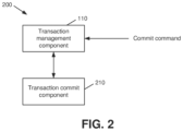
- system 200 includes a transaction commit component 210 that can commit a data transaction, e.g., at a primary participant node 10 or a secondary participant node 12 , in response to receiving a corresponding transaction commit command.
- a participant node 10 can utilize the transaction commit component 210 as shown in FIG. 2 to provide baseline commit functionality for a transaction, and this baseline functionality can be augmented by the components 110 , 120 , 130 of system 100 as described above to complete data transactions, such as 2PCv2 transactions or the like, based on the operational state of a secondary (buddy) participant node 12 , e.g., as determined by the state monitoring component 120 .
- system 300 in FIG. 3 illustrates respective operations that can be performed by an initiator node 20 and a primary participant node 10 to confirm a transaction where a secondary participant node 12 has failed or otherwise has not responded to a transaction commit command from the initiator node 20 .
- the primary participant node 10 in the event that a secondary participant node 12 to the transaction is disconnected or otherwise does not respond for a configurable period of time, the primary participant node 10 can mark the secondary participant node 12 as invalid, e.g., in an NSB or other data structure 30 via a state update component 130 as described above. Subsequently, the primary participant node 10 can commit the transaction via the transaction commit component 210 and respond to the initiator node 20 with its own responsive message (e.g., via the transaction management component 110 ).
- the primary participant node 10 can continue a transaction to completion, even in a case where the secondary participant node 12 has timed out and/or otherwise failed, by dropping the secondary participant node 12 from the transaction in response to marking the secondary participant node 12 as invalid in the data structure 30 .
- the transaction shown in system 300 relates to journal mirroring
- any journal restore following a journal loss can consult the data structure 30 (e.g., via an NSB)
- the validity information in the data structure 30 can avoid using stale information corresponding to the secondary participant node 12 in future transactions.
- system 400 in FIG. 4 illustrates a case in which the secondary participant node 12 remains responsive throughout the transaction.
- the primary participant node 10 can respond to a commit command provided by the initiator node 20 by committing the transaction at the primary participant node 10 in a similar manner to that described above with respect to FIG. 3 .
- the primary participant node 10 in response to the state monitoring component 120 determining that the secondary participant node 12 is active, e.g., due to a response to the commit command from the initiator node 20 being received at the primary participant node 10 , the primary participant node 10 can be configured to respond to the initiator node 20 only after receiving the response from the secondary participant node 12 .
- the primary participant node 10 can record, e.g., in an associated journal, that it has received a commit command from the initiator node 20 for later use.
- the primary participant node 10 can (e.g., via the transaction management component 110 ) generate a response to the commit command for the primary participant node 10 and send this response, along with the response received from the secondary participant node 12 , back to the initiator node 20 .
- the primary participant node 10 can facilitate participant-driven transaction commit by acting as an intermediary between the secondary participant node 12 and the initiator node 20 during the commit phase of a transaction.
- the initiator node 20 as shown in system 400 can submit a commit command directly to the secondary participant node 12
- the secondary participant node 12 once committed, can be configured to respond only to the primary participant node 10 with a response to the commit command, i.e., without responding to the initiator node 20 directly.
- the secondary participant node 12 can be configured to receive transaction messages only from the initiator node 20 and the primary participant node 10 and to respond only to said nodes.
- FIG. 5 a diagram 500 depicting an example messaging flow for a 2PCv2 transaction, e.g., a transaction associated with a file system write and/or a similar operation, is illustrated.
- the messaging flow illustrated by diagram 500 can be conducted between an initiator 502 that initiates updates to one or more data or metadata blocks (e.g., one or more blocks corresponding to a file, etc.), a primary participant 504 that is associated with the respective blocks to be updated and a primary journal corresponding to the transaction, and a buddy (secondary) participant associated with a buddy (secondary) journal that corresponds to the primary journal of the primary participant 504 .
- data or metadata blocks e.g., one or more blocks corresponding to a file, etc.
- a primary participant 504 that is associated with the respective blocks to be updated and a primary journal corresponding to the transaction
- a buddy (secondary) participant associated with a buddy (secondary) journal that corresponds to the primary journal of the primary participant 504 .
- one or more buddy participants 506 can be assigned to a given primary participant 504 prior to the messaging flow shown by diagram 500 via a static buddy nomination scheme and/or by other means. For instance, for each storage node in the system identified by a device identifier X, the storage node of the system having the next highest device identifier (e.g., wrapped upwards) can be nominated as a buddy for the storage node. Other schemes could also be used.
- the initiator 502 can fetch a generation indicator and/or other information for each primary participant 504 from group management protocol (GMP) group information and/or other suitable information prior to the messaging flow shown in diagram 500 .
- GMP group management protocol
- the initiator 502 can send transaction start (txn_start) messages to the primary participant(s) 504 and the buddy participant(s) 506 , respectively.
- the initiator 502 can send the txn_start messages to the primary participant(s) 504 and the buddy participant(s) 506 in parallel, e.g., as a common message directed toward both sets of participants 504 , 506 , and/or in separate messages.
- the txn_start messages sent by the initiator 502 at time 510 can include verification information, such as a generation number and/or generation indicator for a primary journal, e.g., as obtained by the initiator 502 prior to time 510 .
- the initiator 502 can send write and/or delta messages to the primary participant 504 that collectively include a replica of the blocks to be updated at the primary participant 504 .
- the initiator 502 can also send a similar message with the same payload to the buddy participant 506 .
- subsequent resolution of the transaction can proceed per 2PCv2 protocol.
- the initiator 502 can send transaction prepare (txn_prepare) messages at time 230 to the primary participant(s) 504 and buddy participant(s) 506 , which can in turn respond with transaction prepared (txn_prepared) messages at times 240 and 242 , respectively.
- the initiator 502 can then send transaction commit (txn_commit) messages at time 550 to the primary participant(s) 504 and buddy participant(s) 506 , which can in turn respond with transaction committed (txn_committed) messages at times 260 and 262 , respectively.
- the messaging flow can then conclude at time 570 , during which the initiator 502 sends txn_committed messages back to the primary participant(s) 504 and buddy participant(s) 506 in order to confirm the transaction.
- the messaging flow shown by diagram 500 has two phases, e.g., a prepare phase and a commit phase.
- the prepare phase the initiator 502 sends txn_prepare messages to the primary participant 504 and buddy participant 506 , e.g., at time 530 .
- the primary participant 504 and buddy participant 506 then respond with txn_prepared messages at times 540 and 542 , respectively. Any failures of the initiator 502 , primary participant 504 , or buddy participant 506 at this phase can result in the transaction being aborted.
- the initiator 502 receives txn_prepared messages from each primary participant 504 and buddy participant 506 to the transaction, it sends txn_commit messages to the primary participant 504 and buddy participant 506 , e.g., at time 550 .
- the primary participant 504 and buddy participant 506 then respond to the initiator 502 with txn_committed messages at times 560 and 562 , respectively.
- the initiator 502 can then wait for the first txn_committed response from either the primary participant 504 or buddy participant 506 before making the resolution of the transaction available to its callers.
- the procedure described above for the commit phase of a transaction can be modified in the case of a transaction utilizing shared and non-shared participants, as will be further discussed below with respect to FIG. 9 .
- FIG. 6 Another example messaging flow that can be conducted between an initiator 502 , primary participant 504 , and buddy participant 506 to facilitate improved fault tolerance is shown by diagram 600 in FIG. 6 .
- the messaging flow shown by diagram 600 can operate in a similar manner to the messaging flow shown by diagram 500 for the prepare phase of the transaction, e.g., from time 510 to time 542 , via initiator-driven transaction mirroring.
- the messaging flow shown by diagram 600 can transition to a participant-driven transaction model for the commit phase of the transaction.
- the primary participant 504 can wait until the buddy participant 506 commits the transaction before proceeding.
- the messaging flow shown in diagram 600 proceeds to time 660 from time 550 , in which the buddy participant 506 sends a txn_committed message to the primary participant 504 , e.g., instead of the initiator 502 .
- the primary participant 504 can then send a txn_committed message to the initiator 502 at time 662 that indicates that the transaction has been committed at both the primary participant 504 and buddy participant 506 .
- the initiator 502 can respond to the txn_committed message provided at 662 by sending a txn_committed message to the primary participant 504 and buddy participant 506 , e.g., at time 570 as described above.
- the use of a participant-driven model for the commit phase of a transaction as shown by diagram 600 can establish tolerance by the transaction to a failure of the buddy participant 506 , since the buddy participant 506 responds only to the primary participant 504 in the commit phase.
- the primary participant 504 can confirm commitment of the transaction to the initiator 502 , thereby enabling the transaction to successfully complete.
- FIG. 7 a block diagram of a system that facilitates conducting a participant-driven data transaction in response to unavailability of an initiator node 20 in accordance with various aspects described herein is illustrated. Repetitive description of like elements employed in other embodiments described herein is omitted for brevity.
- an initiator node 20 for a transaction can submit a transaction prepare command to a primary participant node 10 and/or a secondary participant node 12 , e.g., as part of the prepare phase of the transaction.
- a primary participant node 10 and/or a secondary participant node 12 e.g., as part of the prepare phase of the transaction.
- the primary participant node 10 of system 700 includes a transaction driver component 710 that, in response to determining that the initiator node 20 has disconnected and/or is otherwise unavailable, can transmit a response to the prepare command to an associated secondary participant node 12 , e.g., in place of the initiator node 20 .
- a transaction can be conducted by a primary participant node 10 via an initiator-driven prepare phase and a participant-driven commit phase.
- the primary participant node 10 e.g., via the transaction driver component 710 , can respond to prepared messages (e.g., txn_prepared messages as shown in FIGS. 5 - 6 ) from other primary participants to the transaction (not shown in FIG. 7 ) only after confirming the transaction state with its secondary participant node 12 .
- prepared messages e.g., txn_prepared messages as shown in FIGS. 5 - 6
- the primary participant node 10 can first send a txn_prepared message to its secondary participant node 12 . If the secondary participant node 12 has prepared the transaction, it can record the txn_prepared message from the primary participant node 10 and respond back to the primary participant node 10 in response to receiving a txn_commit or txn_abort message from the initiator node 20 . Thus, if the secondary participant node 12 is still connected to the initiator node 20 , it can be configured to not respond until the transaction is aborted or committed by the initiator node 20 .
- the secondary participant node 12 can be configured to respond only to its primary participant node 10 . For instance, in response to determining that the initiator node 20 has disconnected, the secondary participant node 12 can send a txn_prepared message to its primary participant node 10 . Subsequently, the secondary participant node 12 can be configured to receive txn_aborted and/or txn_committed messages from other primary participants and, upon receipt, record said messages and forward them to the primary participant node 10 . In doing so, the secondary participant node 12 can be prevented from committing a transaction while the primary participant node 10 and any other primary participants can abort the transaction.
- the transaction driver component 710 of the primary participant node can commit the transaction for which the prepare command was previously received from the initiator node, e.g., in a similar manner to the transaction commit component 210 as described above. This can be done, for example, in response to receiving a responsive message from the secondary participant node 12 that indicates that the transaction has been committed at the secondary participant node 12 .
- the primary participant node 10 of system 800 further includes a transaction confirmation component 810 , which can transmit a commit confirmation message to the secondary participant node 12 and/or one or more other nodes in response to the transaction being committed at the primary participant node 10 .
- the transaction confirmation component 810 can broadcast txn_committed messages to respective other participants in the transaction, including the secondary participant node 12 as well as any other primary or secondary participants to the transaction (not shown in FIG. 8 ).
- the secondary participant node 12 in the event that the secondary participant node 12 as shown by FIGS. 7 - 8 is disconnected from the initiator node 20 during a transaction, the secondary participant node 12 can be configured to respond only to its assigned primary participant node 10 .
- the secondary participant node 12 in this example can be configured to not respond to other primary or secondary participants.
- system 900 includes a computing device 902 , which is a physical machine, or cluster or arrangement of physical machines, on which both the initiator node 20 and the primary participant node 10 are located. Due to the implementation of the primary participant node 10 on the same computing device 902 as the initiator node 20 (e.g., as a separate logical entity, etc.), primary participant node 10 in system 900 is referred to as a shared participant.
- a shared participant can operate differently to a non-shared (or “normal”) participant as described above in order to retain single failure non-blocking semantics.
- a shared participant in 2PCv2 differs from normal participants in that the initiator node 20 does not send a shared participant a commit message.
- a shared participant can be a non-journaled pseudo-participant in a transaction.
- an initiator node 20 can send commit commands 910 , e.g., txn_commit messages as described above, to respective normal participants to the transaction, here a secondary participant node 12 and a normal primary participant node 14 .
- the shared primary participant node 10 can be configured to wait for responsive messages 920 to the commit commands 910 , e.g., txn_committed messages as described above, before committing the transaction.
- a shared primary participant node 10 can handle a disconnect and/or unresponsiveness of an associated secondary participant node 12 by marking it as invalid, e.g., in an NSB or other data structure 30 as described above with respect to FIG. 1 .
- a shared secondary participant does not receive a commit command, such as a txn_commit message, from the initiator node 20 .
- a shared secondary participant can be configured to commit a transaction only after receiving a txn_committed message and/or another suitable commit response from any other normal primary participants to the transaction.
- a system operatively coupled to a processor can receive and/or otherwise obtain (e.g., by a transaction management component 110 ) a commit command for a data transaction (e.g., a txn_commit message) from an initiator node of the system (e.g., an initiator node 20 ).
- a commit command for a data transaction e.g., a txn_commit message
- the data transaction can be associated with a first failure domain, and the commit command can be directed to a primary participant node (e.g., a primary participant node 10 ) and a secondary (buddy) participant node (e.g., a secondary participant node 12 ) of the system.
- a primary participant node e.g., a primary participant node 10
- a secondary (buddy) participant node e.g., a secondary participant node 12
- the system can determine (e.g., by a state monitoring component 120 ) whether a response (e.g., a txn_committed message) to the commit command received at 1002 has been received at the primary participant node from the secondary participant node.
- a response e.g., a txn_committed message
- the system can indicate (e.g., by a state update component 130 ) that the secondary participant node is invalid in a data store (e.g., an NSB or other data structure 30 ) associated with a second failure domain that is distinct from the failure domain associated with the transaction at 1002 .
- a state update component 130 e.g., an NSB or other data structure 30
- FIG. 10 illustrates a method in accordance with certain aspects of this disclosure. While, for purposes of simplicity of explanation, the method has been shown and described as series of acts, it is to be understood and appreciated that this disclosure is not limited by the order of acts, as some acts may occur in different orders and/or concurrently with other acts from that shown and described herein. For example, those skilled in the art will understand and appreciate that methods can alternatively be represented as a series of interrelated states or events, such as in a state diagram. Moreover, not all illustrated acts may be required to implement methods in accordance with certain aspects of this disclosure.
- FIG. 11 and the following discussion are intended to provide a brief, general description of a suitable computing environment 1100 in which the various embodiments of the embodiment described herein can be implemented. While the embodiments have been described above in the general context of computer-executable instructions that can run on one or more computers, those skilled in the art will recognize that the embodiments can be also implemented in combination with other program modules and/or as a combination of hardware and software.
- program modules include routines, programs, components, data structures, etc., that perform particular tasks or implement particular abstract data types.
- program modules include routines, programs, components, data structures, etc., that perform particular tasks or implement particular abstract data types.
- program modules include routines, programs, components, data structures, etc., that perform particular tasks or implement particular abstract data types.
- program modules include routines, programs, components, data structures, etc., that perform particular tasks or implement particular abstract data types.
- IoT Internet of Things
- the illustrated embodiments of the embodiments herein can be also practiced in distributed computing environments where certain tasks are performed by remote processing devices that are linked through a communications network.
- program modules can be located in both local and remote memory storage devices.
- Computer-readable storage media or machine-readable storage media can be any available storage media that can be accessed by the computer and includes both volatile and nonvolatile media, removable and non-removable media.
- Computer-readable storage media or machine-readable storage media can be implemented in connection with any method or technology for storage of information such as computer-readable or machine-readable instructions, program modules, structured data or unstructured data.
- Computer-readable storage media can include, but are not limited to, random access memory (RAM), read only memory (ROM), electrically erasable programmable read only memory (EEPROM), flash memory or other memory technology, compact disk read only memory (CD-ROM), digital versatile disk (DVD), Blu-ray disc (BD) or other optical disk storage, magnetic cassettes, magnetic tape, magnetic disk storage or other magnetic storage devices, solid state drives or other solid state storage devices, or other tangible and/or non-transitory media which can be used to store desired information.
- RAM random access memory
- ROM read only memory
- EEPROM electrically erasable programmable read only memory
- flash memory or other memory technology
- CD-ROM compact disk read only memory
- DVD digital versatile disk
- Blu-ray disc (BD) or other optical disk storage magnetic cassettes, magnetic tape, magnetic disk storage or other magnetic storage devices, solid state drives or other solid state storage devices, or other tangible and/or non-transitory media which can be used to store desired information.
- tangible or “non-transitory” herein as applied to storage, memory or computer-readable media, are to be understood to exclude only propagating transitory signals per se as modifiers and do not relinquish rights to all standard storage, memory or computer-readable media that are not only propagating transitory signals per se.
- Computer-readable storage media can be accessed by one or more local or remote computing devices, e.g., via access requests, queries or other data retrieval protocols, for a variety of operations with respect to the information stored by the medium.
- Communications media typically embody computer-readable instructions, data structures, program modules or other structured or unstructured data in a data signal such as a modulated data signal, e.g., a carrier wave or other transport mechanism, and includes any information delivery or transport media.
- modulated data signal or signals refers to a signal that has one or more of its characteristics set or changed in such a manner as to encode information in one or more signals.
- communication media include wired media, such as a wired network or direct-wired connection, and wireless media such as acoustic, RF, infrared and other wireless media.
- the example environment 1100 for implementing various embodiments of the aspects described herein includes a computer 1102 , the computer 1102 including a processing unit 1104 , a system memory 1106 and a system bus 1108 .
- the system bus 1108 couples system components including, but not limited to, the system memory 1106 to the processing unit 1104 .
- the processing unit 1104 can be any of various commercially available processors. Dual microprocessors and other multi-processor architectures can also be employed as the processing unit 1104 .
- the system bus 1108 can be any of several types of bus structure that can further interconnect to a memory bus (with or without a memory controller), a peripheral bus, and a local bus using any of a variety of commercially available bus architectures.
- the system memory 1106 includes ROM 1110 and RAM 1112 .
- a basic input/output system (BIOS) can be stored in a non-volatile memory such as ROM, erasable programmable read only memory (EPROM), EEPROM, which BIOS contains the basic routines that help to transfer information between elements within the computer 1102 , such as during startup.
- the RAM 1112 can also include a high-speed RAM such as static RAM for caching data.
- the computer 1102 further includes an internal hard disk drive (HDD) 1114 (e.g., EIDE, SATA), one or more external storage devices 1116 (e.g., a magnetic floppy disk drive (FDD), a memory stick or flash drive reader, a memory card reader, etc.) and an optical disk drive 1120 (e.g., which can read or write from a CD-ROM disc, a DVD, a BD, etc.).
- HDD hard disk drive
- FDD magnetic floppy disk drive
- FDD magnetic floppy disk drive
- memory stick or flash drive reader e.g., a memory stick or flash drive reader
- a memory card reader e.g., a memory card reader
- optical disk drive 1120 e.g., which can read or write from a CD-ROM disc, a DVD, a BD, etc.
- SSD solid state drive
- the HDD 1114 , external storage device(s) 1116 and optical disk drive 1120 can be connected to the system bus 1108 by an HDD interface 1124 , an external storage interface 1126 and an optical drive interface 1128 , respectively.
- the interface 1124 for external drive implementations can include at least one or both of Universal Serial Bus (USB) and Institute of Electrical and Electronics Engineers (IEEE) 1394 interface technologies. Other external drive connection technologies are within contemplation of the embodiments described herein.
- the drives and their associated computer-readable storage media provide nonvolatile storage of data, data structures, computer-executable instructions, and so forth.
- the drives and storage media accommodate the storage of any data in a suitable digital format.
- computer-readable storage media refers to respective types of storage devices, it should be appreciated by those skilled in the art that other types of storage media which are readable by a computer, whether presently existing or developed in the future, could also be used in the example operating environment, and further, that any such storage media can contain computer-executable instructions for performing the methods described herein.
- a number of program modules can be stored in the drives and RAM 1112 , including an operating system 1130 , one or more application programs 1132 , other program modules 1134 and program data 1136 . All or portions of the operating system, applications, modules, and/or data can also be cached in the RAM 1112 .
- the systems and methods described herein can be implemented utilizing various commercially available operating systems or combinations of operating systems.
- Computer 1102 can optionally comprise emulation technologies.
- a hypervisor (not shown) or other intermediary can emulate a hardware environment for operating system 1130 , and the emulated hardware can optionally be different from the hardware illustrated in FIG. 11 .
- operating system 1130 can comprise one virtual machine (VM) of multiple VMs hosted at computer 1102 .
- VM virtual machine
- operating system 1130 can provide runtime environments, such as the Java runtime environment or the .NET framework, for applications 1132 . Runtime environments are consistent execution environments that allow applications 1132 to run on any operating system that includes the runtime environment.
- operating system 1130 can support containers, and applications 1132 can be in the form of containers, which are lightweight, standalone, executable packages of software that include, e.g., code, runtime, system tools, system libraries and settings for an application.
- computer 1102 can be enable with a security module, such as a trusted processing module (TPM).
- TPM trusted processing module
- boot components hash next in time boot components, and wait for a match of results to secured values, before loading a next boot component.
- This process can take place at any layer in the code execution stack of computer 1102 , e.g., applied at the application execution level or at the operating system (OS) kernel level, thereby enabling security at any level of code execution.
- OS operating system
- a user can enter commands and information into the computer 1102 through one or more wired/wireless input devices, e.g., a keyboard 1138 , a touch screen 1140 , and a pointing device, such as a mouse 1142 .
- Other input devices can include a microphone, an infrared (IR) remote control, a radio frequency (RF) remote control, or other remote control, a joystick, a virtual reality controller and/or virtual reality headset, a game pad, a stylus pen, an image input device, e.g., camera(s), a gesture sensor input device, a vision movement sensor input device, an emotion or facial detection device, a biometric input device, e.g., fingerprint or iris scanner, or the like.
- IR infrared
- RF radio frequency
- input devices are often connected to the processing unit 1104 through an input device interface 1144 that can be coupled to the system bus 1108 , but can be connected by other interfaces, such as a parallel port, an IEEE 1394 serial port, a game port, a USB port, an IR interface, a BLUETOOTH® interface, etc.
- a monitor 1146 or other type of display device can be also connected to the system bus 1108 via an interface, such as a video adapter 1148 .
- a computer typically includes other peripheral output devices (not shown), such as speakers, printers, etc.
- the computer 1102 can operate in a networked environment using logical connections via wired and/or wireless communications to one or more remote computers, such as a remote computer(s) 1150 .
- the remote computer(s) 1150 can be a workstation, a server computer, a router, a personal computer, portable computer, microprocessor-based entertainment appliance, a peer device or other common network node, and typically includes many or all of the elements described relative to the computer 1102 , although, for purposes of brevity, only a memory/storage device 1152 is illustrated.
- the logical connections depicted include wired/wireless connectivity to a local area network (LAN) 1154 and/or larger networks, e.g., a wide area network (WAN) 1156 .
- LAN and WAN networking environments are commonplace in offices and companies, and facilitate enterprise-wide computer networks, such as intranets, all of which can connect to a global communications network, e.g., the Internet.
- the computer 1102 can be connected to the local network 1154 through a wired and/or wireless communication network interface or adapter 1158 .
- the adapter 1158 can facilitate wired or wireless communication to the LAN 1154 , which can also include a wireless access point (AP) disposed thereon for communicating with the adapter 1158 in a wireless mode.
- AP wireless access point
- the computer 1102 can include a modem 1160 or can be connected to a communications server on the WAN 1156 via other means for establishing communications over the WAN 1156 , such as by way of the Internet.
- the modem 1160 which can be internal or external and a wired or wireless device, can be connected to the system bus 1108 via the input device interface 1144 .
- program modules depicted relative to the computer 1102 or portions thereof can be stored in the remote memory/storage device 1152 . It will be appreciated that the network connections shown are example and other means of establishing a communications link between the computers can be used.
- the computer 1102 can access cloud storage systems or other network-based storage systems in addition to, or in place of, external storage devices 1116 as described above.
- a connection between the computer 1102 and a cloud storage system can be established over a LAN 1154 or WAN 1156 e.g., by the adapter 1158 or modem 1160 , respectively.
- the external storage interface 1126 can, with the aid of the adapter 1158 and/or modem 1160 , manage storage provided by the cloud storage system as it would other types of external storage.
- the external storage interface 1126 can be configured to provide access to cloud storage sources as if those sources were physically connected to the computer 1102 .
- the computer 1102 can be operable to communicate with any wireless devices or entities operatively disposed in wireless communication, e.g., a printer, scanner, desktop and/or portable computer, portable data assistant, communications satellite, any piece of equipment or location associated with a wirelessly detectable tag (e.g., a kiosk, news stand, store shelf, etc.), and telephone.
- any wireless devices or entities operatively disposed in wireless communication e.g., a printer, scanner, desktop and/or portable computer, portable data assistant, communications satellite, any piece of equipment or location associated with a wirelessly detectable tag (e.g., a kiosk, news stand, store shelf, etc.), and telephone.
- This can include Wireless Fidelity (Wi-Fi) and BLUETOOTH® wireless technologies.
- Wi-Fi Wireless Fidelity
- BLUETOOTH® wireless technologies can be a predefined structure as with a conventional network or simply an ad hoc communication between at least two devices.
- the terms (including a reference to a “means”) used to describe such components are intended to also include, unless otherwise indicated, any structure(s) which performs the specified function of the described component (e.g., a functional equivalent), even if not structurally equivalent to the disclosed structure.
- any structure(s) which performs the specified function of the described component e.g., a functional equivalent
- a particular feature of the disclosed subject matter may have been disclosed with respect to only one of several implementations, such feature may be combined with one or more other features of the other implementations as may be desired and advantageous for any given or particular application.
- exemplary and/or “demonstrative” as used herein are intended to mean serving as an example, instance, or illustration. For the avoidance of doubt, the subject matter disclosed herein is not limited by such examples.
- any aspect or design described herein as “exemplary” and/or “demonstrative” is not necessarily to be construed as preferred or advantageous over other aspects or designs, nor is it meant to preclude equivalent structures and techniques known to one skilled in the art.
- the terms “includes,” “has,” “contains,” and other similar words are used in either the detailed description or the claims, such terms are intended to be inclusive—in a manner similar to the term “comprising” as an open transition word—without precluding any additional or other elements.
- set as employed herein excludes the empty set, i.e., the set with no elements therein.
- a “set” in the subject disclosure includes one or more elements or entities.
- group as utilized herein refers to a collection of one or more entities.
- first is for clarity only and doesn't otherwise indicate or imply any order in time. For instance, “a first determination,” “a second determination,” and “a third determination,” does not indicate or imply that the first determination is to be made before the second determination, or vice versa, etc.
Abstract
Description
Claims (20)
Priority Applications (4)
| Application Number | Priority Date | Filing Date | Title |
|---|---|---|---|
| US17/083,991 US11669516B2 (en) | 2020-10-29 | 2020-10-29 | Fault tolerance for transaction mirroring |
| PCT/US2021/028998 WO2022093311A1 (en) | 2020-10-29 | 2021-04-23 | Fault tolerance for transaction mirroring |
| DE112021005752.9T DE112021005752T5 (en) | 2020-10-29 | 2021-04-23 | Fault tolerance for transaction mirroring |
| CN202180042436.5A CN115698955A (en) | 2020-10-29 | 2021-04-23 | Fault tolerance of transaction images |
Applications Claiming Priority (1)
| Application Number | Priority Date | Filing Date | Title |
|---|---|---|---|
| US17/083,991 US11669516B2 (en) | 2020-10-29 | 2020-10-29 | Fault tolerance for transaction mirroring |
Publications (2)
| Publication Number | Publication Date |
|---|---|
| US20220138177A1 US20220138177A1 (en) | 2022-05-05 |
| US11669516B2 true US11669516B2 (en) | 2023-06-06 |
Family
ID=75905066
Family Applications (1)
| Application Number | Title | Priority Date | Filing Date |
|---|---|---|---|
| US17/083,991 Active 2041-07-16 US11669516B2 (en) | 2020-10-29 | 2020-10-29 | Fault tolerance for transaction mirroring |
Country Status (4)
| Country | Link |
|---|---|
| US (1) | US11669516B2 (en) |
| CN (1) | CN115698955A (en) |
| DE (1) | DE112021005752T5 (en) |
| WO (1) | WO2022093311A1 (en) |
Families Citing this family (1)
| Publication number | Priority date | Publication date | Assignee | Title |
|---|---|---|---|---|
| CN115729667A (en) * | 2021-08-25 | 2023-03-03 | 富联精密电子(天津)有限公司 | Virtual machine migration method, electronic device and storage medium |
Citations (4)
| Publication number | Priority date | Publication date | Assignee | Title |
|---|---|---|---|---|
| US20060095438A1 (en) | 2004-10-29 | 2006-05-04 | Fachan Neal T | Non-blocking commit protocol systems and methods |
| US7873619B1 (en) * | 2008-03-31 | 2011-01-18 | Emc Corporation | Managing metadata |
| US20150006846A1 (en) * | 2013-06-28 | 2015-01-01 | Saratoga Speed, Inc. | Network system to distribute chunks across multiple physical nodes with disk support for object storage |
| US20180322157A1 (en) | 2017-05-08 | 2018-11-08 | Sap Se | Adaptive query routing in a replicated database environment |
-
2020
- 2020-10-29 US US17/083,991 patent/US11669516B2/en active Active
-
2021
- 2021-04-23 CN CN202180042436.5A patent/CN115698955A/en active Pending
- 2021-04-23 DE DE112021005752.9T patent/DE112021005752T5/en active Pending
- 2021-04-23 WO PCT/US2021/028998 patent/WO2022093311A1/en active Application Filing
Patent Citations (4)
| Publication number | Priority date | Publication date | Assignee | Title |
|---|---|---|---|---|
| US20060095438A1 (en) | 2004-10-29 | 2006-05-04 | Fachan Neal T | Non-blocking commit protocol systems and methods |
| US7873619B1 (en) * | 2008-03-31 | 2011-01-18 | Emc Corporation | Managing metadata |
| US20150006846A1 (en) * | 2013-06-28 | 2015-01-01 | Saratoga Speed, Inc. | Network system to distribute chunks across multiple physical nodes with disk support for object storage |
| US20180322157A1 (en) | 2017-05-08 | 2018-11-08 | Sap Se | Adaptive query routing in a replicated database environment |
Non-Patent Citations (2)
| Title |
|---|
| International Search Report and Written Opinion for International Application No. PCT/US2021/028998 dated Aug. 3, 2021, 17 pages. |
| Raju, et al., "System and Method for Mirroring a File System Journal," U.S. Appl. No. 16/943,576, filed Jul. 30, 2020, 38 pages. |
Also Published As
| Publication number | Publication date |
|---|---|
| US20220138177A1 (en) | 2022-05-05 |
| DE112021005752T5 (en) | 2023-09-28 |
| CN115698955A (en) | 2023-02-03 |
| WO2022093311A1 (en) | 2022-05-05 |
Similar Documents
| Publication | Publication Date | Title |
|---|---|---|
| USRE47852E1 (en) | Snapshot and replication of a multi-stream application on multiple hosts at near-sync frequency | |
| CN106843749B (en) | Write request processing method, device and equipment | |
| US11163479B2 (en) | Replicated state cluster with standby node state assessment during leadership transition | |
| JP6181290B2 (en) | Transaction ordering | |
| US8464101B1 (en) | CAS command network replication | |
| US8949180B1 (en) | Replicating key-value pairs in a continuous data protection system | |
| US8301600B1 (en) | Failover recovery in a distributed data store | |
| US11379329B2 (en) | Validation of data written via two different bus interfaces to a dual server based storage controller | |
| US9830263B1 (en) | Cache consistency | |
| US11669516B2 (en) | Fault tolerance for transaction mirroring | |
| US10169441B2 (en) | Synchronous data replication in a content management system | |
| US11340967B2 (en) | High availability events in a layered architecture | |
| WO2015196692A1 (en) | Cloud computing system and processing method and apparatus for cloud computing system | |
| US11507545B2 (en) | System and method for mirroring a file system journal | |
| US11016863B2 (en) | Self-contained disaster detection for replicated multi-controller systems | |
| US11422715B1 (en) | Direct read in clustered file systems | |
| US11238010B2 (en) | Sand timer algorithm for tracking in-flight data storage requests for data replication | |
| WO2019109257A1 (en) | Log management method, server and database system | |
| US11734122B2 (en) | Backup task processing in a data storage system | |
| US20210216568A1 (en) | Efficient configuration replication using a configuration change log | |
| US11669501B2 (en) | Address mirroring of a file system journal | |
| US20240028480A1 (en) | Fast disaster recover from backup storage using smart links | |
| US11347427B2 (en) | Separation of dataset creation from movement in file replication | |
| WO2023075995A1 (en) | Techniques for stateful persisted service resource reduction |
Legal Events
| Date | Code | Title | Description |
|---|---|---|---|
| AS | Assignment |
Owner name: EMC IP HOLDING COMPANY LLC, MASSACHUSETTS Free format text: ASSIGNMENT OF ASSIGNORS INTEREST;ASSIGNORS:RAJU, SURAJ BRAHMA;LAIER, MAX;STEINKE, RONALD;REEL/FRAME:054213/0444 Effective date: 20201028 |
|
| FEPP | Fee payment procedure |
Free format text: ENTITY STATUS SET TO UNDISCOUNTED (ORIGINAL EVENT CODE: BIG.); ENTITY STATUS OF PATENT OWNER: LARGE ENTITY |
|
| AS | Assignment |
Owner name: CREDIT SUISSE AG, CAYMAN ISLANDS BRANCH, NORTH CAROLINA Free format text: SECURITY AGREEMENT;ASSIGNORS:EMC IP HOLDING COMPANY LLC;DELL PRODUCTS L.P.;REEL/FRAME:054591/0471 Effective date: 20201112 |
|
| AS | Assignment |
Owner name: THE BANK OF NEW YORK MELLON TRUST COMPANY, N.A., AS NOTES COLLATERAL AGENT, TEXAS Free format text: SECURITY INTEREST;ASSIGNORS:EMC IP HOLDING COMPANY LLC;DELL PRODUCTS L.P.;REEL/FRAME:054475/0523 Effective date: 20201113 Owner name: THE BANK OF NEW YORK MELLON TRUST COMPANY, N.A., AS COLLATERAL AGENT, TEXAS Free format text: SECURITY INTEREST;ASSIGNORS:EMC IP HOLDING COMPANY LLC;DELL PRODUCTS L.P.;REEL/FRAME:054475/0609 Effective date: 20201113 Owner name: THE BANK OF NEW YORK MELLON TRUST COMPANY, N.A., AS NOTES COLLATERAL AGENT, TEXAS Free format text: SECURITY INTEREST;ASSIGNORS:EMC IP HOLDING COMPANY LLC;DELL PRODUCTS L.P.;REEL/FRAME:054475/0434 Effective date: 20201113 |
|
| STPP | Information on status: patent application and granting procedure in general |
Free format text: DOCKETED NEW CASE - READY FOR EXAMINATION |
|
| AS | Assignment |
Owner name: EMC IP HOLDING COMPANY LLC, TEXAS Free format text: RELEASE OF SECURITY INTEREST AT REEL 054591 FRAME 0471;ASSIGNOR:CREDIT SUISSE AG, CAYMAN ISLANDS BRANCH;REEL/FRAME:058001/0463 Effective date: 20211101 Owner name: DELL PRODUCTS L.P., TEXAS Free format text: RELEASE OF SECURITY INTEREST AT REEL 054591 FRAME 0471;ASSIGNOR:CREDIT SUISSE AG, CAYMAN ISLANDS BRANCH;REEL/FRAME:058001/0463 Effective date: 20211101 |
|
| AS | Assignment |
Owner name: DELL PRODUCTS L.P., TEXAS Free format text: RELEASE OF SECURITY INTEREST IN PATENTS PREVIOUSLY RECORDED AT REEL/FRAME (054475/0609);ASSIGNOR:THE BANK OF NEW YORK MELLON TRUST COMPANY, N.A., AS NOTES COLLATERAL AGENT;REEL/FRAME:062021/0570 Effective date: 20220329 Owner name: EMC IP HOLDING COMPANY LLC, TEXAS Free format text: RELEASE OF SECURITY INTEREST IN PATENTS PREVIOUSLY RECORDED AT REEL/FRAME (054475/0609);ASSIGNOR:THE BANK OF NEW YORK MELLON TRUST COMPANY, N.A., AS NOTES COLLATERAL AGENT;REEL/FRAME:062021/0570 Effective date: 20220329 Owner name: DELL PRODUCTS L.P., TEXAS Free format text: RELEASE OF SECURITY INTEREST IN PATENTS PREVIOUSLY RECORDED AT REEL/FRAME (054475/0434);ASSIGNOR:THE BANK OF NEW YORK MELLON TRUST COMPANY, N.A., AS NOTES COLLATERAL AGENT;REEL/FRAME:060332/0740 Effective date: 20220329 Owner name: EMC IP HOLDING COMPANY LLC, TEXAS Free format text: RELEASE OF SECURITY INTEREST IN PATENTS PREVIOUSLY RECORDED AT REEL/FRAME (054475/0434);ASSIGNOR:THE BANK OF NEW YORK MELLON TRUST COMPANY, N.A., AS NOTES COLLATERAL AGENT;REEL/FRAME:060332/0740 Effective date: 20220329 Owner name: DELL PRODUCTS L.P., TEXAS Free format text: RELEASE OF SECURITY INTEREST IN PATENTS PREVIOUSLY RECORDED AT REEL/FRAME (054475/0523);ASSIGNOR:THE BANK OF NEW YORK MELLON TRUST COMPANY, N.A., AS NOTES COLLATERAL AGENT;REEL/FRAME:060332/0664 Effective date: 20220329 Owner name: EMC IP HOLDING COMPANY LLC, TEXAS Free format text: RELEASE OF SECURITY INTEREST IN PATENTS PREVIOUSLY RECORDED AT REEL/FRAME (054475/0523);ASSIGNOR:THE BANK OF NEW YORK MELLON TRUST COMPANY, N.A., AS NOTES COLLATERAL AGENT;REEL/FRAME:060332/0664 Effective date: 20220329 |
|
| STPP | Information on status: patent application and granting procedure in general |
Free format text: NON FINAL ACTION MAILED |
|
| STPP | Information on status: patent application and granting procedure in general |
Free format text: RESPONSE TO NON-FINAL OFFICE ACTION ENTERED AND FORWARDED TO EXAMINER |
|
| STCF | Information on status: patent grant |
Free format text: PATENTED CASE |