US1166714A - Expolosive-engine. - Google Patents
Expolosive-engine. Download PDFInfo
- Publication number
- US1166714A US1166714A US73234212A US1912732342A US1166714A US 1166714 A US1166714 A US 1166714A US 73234212 A US73234212 A US 73234212A US 1912732342 A US1912732342 A US 1912732342A US 1166714 A US1166714 A US 1166714A
- Authority
- US
- United States
- Prior art keywords
- cylinder
- engine
- piston
- pistons
- stroke
- Prior art date
- Legal status (The legal status is an assumption and is not a legal conclusion. Google has not performed a legal analysis and makes no representation as to the accuracy of the status listed.)
- Expired - Lifetime
Links
Images

Classifications
-
- F—MECHANICAL ENGINEERING; LIGHTING; HEATING; WEAPONS; BLASTING
- F02—COMBUSTION ENGINES; HOT-GAS OR COMBUSTION-PRODUCT ENGINE PLANTS
- F02B—INTERNAL-COMBUSTION PISTON ENGINES; COMBUSTION ENGINES IN GENERAL
- F02B75/00—Other engines
- F02B75/02—Engines characterised by their cycles, e.g. six-stroke
-
- F—MECHANICAL ENGINEERING; LIGHTING; HEATING; WEAPONS; BLASTING
- F01—MACHINES OR ENGINES IN GENERAL; ENGINE PLANTS IN GENERAL; STEAM ENGINES
- F01L—CYCLICALLY OPERATING VALVES FOR MACHINES OR ENGINES
- F01L1/00—Valve-gear or valve arrangements, e.g. lift-valve gear
- F01L1/02—Valve drive
- F01L1/04—Valve drive by means of cams, camshafts, cam discs, eccentrics or the like
-
- F—MECHANICAL ENGINEERING; LIGHTING; HEATING; WEAPONS; BLASTING
- F02—COMBUSTION ENGINES; HOT-GAS OR COMBUSTION-PRODUCT ENGINE PLANTS
- F02B—INTERNAL-COMBUSTION PISTON ENGINES; COMBUSTION ENGINES IN GENERAL
- F02B75/00—Other engines
- F02B75/02—Engines characterised by their cycles, e.g. six-stroke
- F02B2075/022—Engines characterised by their cycles, e.g. six-stroke having less than six strokes per cycle
- F02B2075/025—Engines characterised by their cycles, e.g. six-stroke having less than six strokes per cycle two
Definitions
- This invention relates to certain novel and useful improvements in combustion engines and has particular. application to an engine employing twin cylinders each of which is provided with two pistons moving in opposite directions in the cylinder. 1
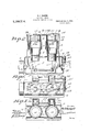
- Figure 1 is a View in side elevation of a vertical explosive en-' gine embodying my invention.
- Fig. 2 is a vertical longitudinal sectional view through the same.
- Fig.3 isaview in end elevation.
- Fig. 4 is a transverse vertical sectional View, taken on the line 44 of Fig. 1.
- Fig. 5 is a cross sectional view takenon the line 55 of Fig. 1.
- Fig. 6 is a top plan view showing the connections of the side arms with the secondary pistons.
- my invention is shown as employed in connection with an engine having twin cylinders and a primary and secondary piston movable in each cylinder, all of said pistons being driven from the crank shaft of the engine.
- thenumeral 1 designates the bed plate carrying the shaft bearings 2 for the crank.
- each of the twin cylinders is designated by the numeral 5 and each cylinder is provided with the usual water jack 6.
- Each cylinder is further divided into two sections, a lower section 7 within which works the primary piston and an upper section 8 in which the secondary piston moves.
- the secondary section 8 of the cylinder is of relatively greater cross dimensions than the primary section 7.
- the two sections of the cylinder may be cast in one piece to form a unitary structure, or may be made of separate sections bolted together at their meeting ends.
- Each cylinder is open at its upper and lower ends and the lower end of each cylinder communicates bythe pitman rod 11- with the intermediate portion of the crank shaft.
- a piston 12 which is of relatively greater cross dimensions than the piston 10.
- Each secondary piston is connected by means of the bearing 13 with the lateral portion 14 of the side arm 15, the latter being in the nature of a pitman rod and is connected at 16 to the crank shaft.
- An intermediate cross rod 17 connects the two pistons of the twin cylinders together.
- the secondary cylinders 8 are provided with vertical confronting slots 18 of sufficient dimension to accommodate the cross connecting rod 17 in its reciprocating movements, and likewise said cylinder sections 8 are provided with vertical slots 19 for the purpose of accommodating the lateral sections 14 of the side arms 15 in the reciprocation of the latter.
- each cylinder is designed to move in opposite directions relatively to each other.
- a port 20 which communicates with the interior of a valve chest or casing 21.
- This casing has a gas inlet port 22 and a gas outlet port 23.
- a valve 24 of any well known type tensioned by the spring 25 controls the inlet port, while a similar valve 26 tensioned by the springs27 controls the outlet port of the casing through which passes the products of combustion.
- the inlet valve is normally closed by its spring and is opened by the suction created by the piston on the piston stroke.
- the outlet valve 26 is opened through the medium of the cam mounted on the shaft 28.
- There is a cam for eachoutlet valve of the engine each cam being indicated by the numeral 29.
- the cam shaft is connected with the crank shaft of the engine through a train of gearing including the gear wheel 30 on the crank shaft,
- gear wheel 31 on the short shaft 32 journaled in the housing, a gear wheel 33 on the shaft 32, a second gear wheel 34 on the cam shaft and a gear 35 connecting the gear wheels 33 and 34.
- the cam shaft is so geared that itmakes one revolution to every two revolutions of the crank shaft.
- each cylinder may be fired by any suitable means when the pistons are in the proper position and the explosion serves to force the pistons in opposite directions to partially turn the crank shaft.
- the movements of the parts are so timed that when the pistons of each cylinder reach the end of their outer stroke the exhaust valve is opened for the passage outward of the products of combustion.
- the discharge of the products of combustion continues until the pistons again reach the innermost end of their strokes.
- the valve 26 controlling the outlet is closed and as the pistons move from the center of the cylinder they create a vacuum which opens the intake valve against the action of its spring so that the gases pass through the port 24 into the cylinder.
- the upper 100 or secondary pistons with their side arms and other moving parts may be made heavier thanthe primary or lower pistons with their connecting rods and other moving parts, and yet the oppositely reciprocating parts will be balanced. That is to say, the ratio between the weight of the oppositely reciprocating parts varies inversely as the length of their stroke. In this case the stroke of the secondary pistons is just one- 11o the weight of the lighter reciprocatingparts are connected to theci 'anks representing a two inch stroke.
- the secondary reciprocating parts will have to weigh twice as much or forty pounds because the lighter reciprocating parts are connected to a crank twice as long as the crank to which the heavier reciprocating parts are connected, these reciprocating parts being supposed to be'loalanced
- the stroke of the 3 secondary pistons being shorter than that of the primary or lower pistons, the strain on the side arms caused by high speed will be greatly reduced as the rate of travel will be less than if both primary and secondary cylinders were of the same diameter.
- each cylinder comprising two sections of relatively different diameters, the larger sections of the cylinders having parallel guide slots formed in the walls thereof, a short stroke secondary piston moving in the larger section of each cylinder, a long stroke primary piston moving in the smaller section of each crank shaft, the opposite end of each piston arm being bent laterally and connected to the adjacent secondary piston, the lateral portions of the arms moving in the slotted guideways in the enlarged sections of the cylinders, said cylinders being each provided with a port at an intermediate section, a valve control passage Way for conducting gas to the port, and a valve control passage way for conducting exploded gas from the ort.
Landscapes
- Engineering & Computer Science (AREA)
- Mechanical Engineering (AREA)
- General Engineering & Computer Science (AREA)
- Chemical & Material Sciences (AREA)
- Combustion & Propulsion (AREA)
- Transmission Devices (AREA)
Description
M. J. RAMESH.
EXPLOSIVE ENGINE.
APPLICATION FILED NOV. 19, 1912.
Patented Jan. 4, 1916.
2 SHEETS'SHEET 1.
I awe/whom M. J. RAMiSH.
v EXPLOSIVE ENGINE. APPLICATION FILED NOV. 1'9, 191;.
1,166,714. Patent-ed Jan. 4, 191 6.
764749 5 a 49 J m 4 7 MATTHEW J. RAMESH, OF 'KEWAUNEE, WISCONSIN.
EXPLOSIVE-ENGINE.
Specification of Letters Patent.
Patented J an. 4, 1916.
Application filed November 19, 1912. Serial No. 732,342.
To all whom it may concern Be it known that I, MATTHEW J. RAMESH, a citizen of the United States, residing at Kewaunee, in the county of Kewaunee, State of Wisconsin, have invented certain new and useful Improvements in Explosive-Engines; and I- do hereby declare the following to be a full, clear, and exact description of the invention, such as will enable others skilled in the art to which it apperta-ins to make and use the same.
This invention relates to certain novel and useful improvements in combustion engines and has particular. application to an engine employing twin cylinders each of which is provided with two pistons moving in opposite directions in the cylinder. 1
In the present instance it is my purpose to provide an engine of the character referred to which is designed to utilize the shock or force of the explosion of the gases in the cylinder for the purpose of driving a secondary pistonin said cylinder which piston is substituted for the ordinary cylinder head.
Furthermore, itis my purpose to provide a cylinder in which the primary and secondary pistons travel, that portion of the cylinder within which the secondary piston works being of relatively greater dimensions than the portion of the cylinder in which the primary piston moves. In my engine the effect of the explosion is divided into two equal parts by decreasing the length of the stroke of the secondary piston according to its increase in area in cross section, and the reciprocatingfparts are balanced by increasing the weight ofthe secondary reciprocating parts in the same proportion as their stroke is decreased. By increasing the area of the secondary piston of each cylinder, its stroke may be shortened. The ratio between the length of stroke of the upper and lower pistonsyaries inversely as areas of their cross sections, or inversely as the square of their diameters. Thus if the square of the diameter of the upper piston is 18 and'of the lower or primary piston is 9, the stroke of the upper-piston, that is the secondary piston, need be but'one-half as long as the stroke of the lower piston, and
the effect of the explosion will be divided and applied equally on each side of the crank shaft. If the stroke of the primary piston is four inches 'the stroke of the secondary piston is two inches, and therefore, each piston transmits an equal amount of power to the crank shaft.
Furthermore, I propose to construct an engine which-will embody the desired features of simplicity, durability and economy, and in which a maximum efliciency is attained with a minimum consumption of fuel.
It is also my purpose to provide an engine wherein all the moving parts are properly balanced so that the'strain and stress thereon, due to the shock and jar of the explosion is reduced to a minimum.
With the above recited objects and others of a similar nature in view, my invention consists in the construction, combination and arrangement of parts set forth in and falling within the scope of the appended claim.
In the drawings: Figure 1 is a View in side elevation of a vertical explosive en-' gine embodying my invention. Fig. 2 is a vertical longitudinal sectional view through the same. Fig.3isaview in end elevation. Fig. 4 isa transverse vertical sectional View, taken on the line 44 of Fig. 1. Fig. 5 is a cross sectional view takenon the line 55 of Fig. 1. Fig. 6 is a top plan view showing the connections of the side arms with the secondary pistons.
In the present instance my invention is shown as employed in connection with an engine having twin cylinders and a primary and secondary piston movable in each cylinder, all of said pistons being driven from the crank shaft of the engine.
Referring now to the drawings in detail,
thenumeral 1 designates the bed plate carrying the shaft bearings 2 for the crank.
shaft 3, the latter being provided with the usual fly wheel 4. Each of the twin cylinders is designated by the numeral 5 and each cylinder is provided with the usual water jack 6. Each cylinder is further divided into two sections, a lower section 7 within which works the primary piston and an upper section 8 in which the secondary piston moves. The secondary section 8 of the cylinder is of relatively greater cross dimensions than the primary section 7. The two sections of the cylinder may be cast in one piece to form a unitary structure, or may be made of separate sections bolted together at their meeting ends. Each cylinder is open at its upper and lower ends and the lower end of each cylinder communicates bythe pitman rod 11- with the intermediate portion of the crank shaft. Likewise within each secondary section 8 of each cylinder works a piston 12 which is of relatively greater cross dimensions than the piston 10. Each secondary piston is connected by means of the bearing 13 with the lateral portion 14 of the side arm 15, the latter being in the nature of a pitman rod and is connected at 16 to the crank shaft. An intermediate cross rod 17 connects the two pistons of the twin cylinders together. The secondary cylinders 8 are provided with vertical confronting slots 18 of sufficient dimension to accommodate the cross connecting rod 17 in its reciprocating movements, and likewise said cylinder sections 8 are provided with vertical slots 19 for the purpose of accommodating the lateral sections 14 of the side arms 15 in the reciprocation of the latter.
From the above descriptions, taken in connection with the drawings, it will be seen that the pistons in each cylinder are designed to move in opposite directions relatively to each other. Intermediate each cylinder is a port 20 which communicates with the interior of a valve chest or casing 21. This casing has a gas inlet port 22 and a gas outlet port 23. A valve 24 of any well known type tensioned by the spring 25 controls the inlet port, while a similar valve 26 tensioned by the springs27 controls the outlet port of the casing through which passes the products of combustion. The inlet valve is normally closed by its spring and is opened by the suction created by the piston on the piston stroke. The outlet valve 26 is opened through the medium of the cam mounted on the shaft 28. There is a cam for eachoutlet valve of the engine, each cam being indicated by the numeral 29. The cam shaft is connected with the crank shaft of the engine through a train of gearing including the gear wheel 30 on the crank shaft,
a gear wheel 31 on the short shaft 32 journaled in the housing, a gear wheel 33 on the shaft 32, a second gear wheel 34 on the cam shaft and a gear 35 connecting the gear wheels 33 and 34. The cam shaft is so geared that itmakes one revolution to every two revolutions of the crank shaft.
While I have herein shown and described one arrangement for'controlling the intake ters, and pistons also having relatively different cross diameters moving in their respective cylinders.
From the above description taken in connection with the accompanying drawings the constructionand operation of my engine will be readily apparent. The charge in each cylinder may be fired by any suitable means when the pistons are in the proper position and the explosion serves to force the pistons in opposite directions to partially turn the crank shaft. The movements of the parts are so timed that when the pistons of each cylinder reach the end of their outer stroke the exhaust valve is opened for the passage outward of the products of combustion. The discharge of the products of combustion continues until the pistons again reach the innermost end of their strokes. The valve 26 controlling the outlet is closed and as the pistons move from the center of the cylinder they create a vacuum which opens the intake valve against the action of its spring so that the gases pass through the port 24 into the cylinder. This inflow of 90) gas continues incident to the outward movement of the pistons and at the limit of such movement the intake valve is closed by the pressure of its spring and on following inward stroke of the pistons the gas in the cylinder is compressed until the pistons reach. the inner ends of their strokes when the explosion takes place and the operation before described is repeated.
By my improved construction the upper 100 or secondary pistons with their side arms and other moving parts may be made heavier thanthe primary or lower pistons with their connecting rods and other moving parts, and yet the oppositely reciprocating parts will be balanced. That is to say, the ratio between the weight of the oppositely reciprocating parts varies inversely as the length of their stroke. In this case the stroke of the secondary pistons is just one- 11o the weight of the lighter reciprocatingparts are connected to theci 'anks representing a two inch stroke. Thus if the primary reciprocating parts weigh twenty pounds, the secondary reciprocating parts will have to weigh twice as much or forty pounds because the lighter reciprocating parts are connected to a crank twice as long as the crank to which the heavier reciprocating parts are connected, these reciprocating parts being supposed to be'loalanced The stroke of the 3 secondary pistons being shorter than that of the primary or lower pistons, the strain on the side arms caused by high speed will be greatly reduced as the rate of travel will be less than if both primary and secondary cylinders were of the same diameter.
It will be seen that I have provided an engine wherein the oppositely reciprocating parts willbe balanced, and which engine is capable of attaining the relatively high speed. without the strain and stretch on the parts which is usually incident to the ordinary engine of this character.
What is claimed is:
In an engine, the combination of twin cylinders, each open at both ends, each cylinder comprising two sections of relatively different diameters, the larger sections of the cylinders having parallel guide slots formed in the walls thereof, a short stroke secondary piston moving in the larger section of each cylinder, a long stroke primary piston moving in the smaller section of each crank shaft, the opposite end of each piston arm being bent laterally and connected to the adjacent secondary piston, the lateral portions of the arms moving in the slotted guideways in the enlarged sections of the cylinders, said cylinders being each provided with a port at an intermediate section, a valve control passage Way for conducting gas to the port, and a valve control passage way for conducting exploded gas from the ort. p In testimony whereof, I afiix my signature, in the presence of two Witnesses.
MATTHEW J. RAMESH. Witnesses:
CARL W. ANDRE, Josnrn RAMEsH.
Priority Applications (1)
| Application Number | Priority Date | Filing Date | Title |
|---|---|---|---|
| US73234212A US1166714A (en) | 1912-11-19 | 1912-11-19 | Expolosive-engine. |
Applications Claiming Priority (1)
| Application Number | Priority Date | Filing Date | Title |
|---|---|---|---|
| US73234212A US1166714A (en) | 1912-11-19 | 1912-11-19 | Expolosive-engine. |
Publications (1)
| Publication Number | Publication Date |
|---|---|
| US1166714A true US1166714A (en) | 1916-01-04 |
Family
ID=3234735
Family Applications (1)
| Application Number | Title | Priority Date | Filing Date |
|---|---|---|---|
| US73234212A Expired - Lifetime US1166714A (en) | 1912-11-19 | 1912-11-19 | Expolosive-engine. |
Country Status (1)
| Country | Link |
|---|---|
| US (1) | US1166714A (en) |
-
1912
- 1912-11-19 US US73234212A patent/US1166714A/en not_active Expired - Lifetime
Similar Documents
| Publication | Publication Date | Title |
|---|---|---|
| US6564762B2 (en) | Gear train crankshaft | |
| US8967097B2 (en) | Variable stroke mechanism for internal combustion engine | |
| US4256068A (en) | Oblong piston and cylinder for internal combustion engine | |
| US3895620A (en) | Engine and gas generator | |
| US3396709A (en) | Roto-piston engine | |
| WO2011029160A1 (en) | Piston and use therefor | |
| US11519305B2 (en) | Internal combustion engine system | |
| US10267225B2 (en) | Internal combustion engine | |
| US4171618A (en) | Fluid operated motor | |
| EP2893166A1 (en) | Variable stroke mechanism for internal combustion engine | |
| US1166714A (en) | Expolosive-engine. | |
| US2153899A (en) | Internal combustion motor | |
| US1080733A (en) | Valve mechanism for engines. | |
| CN102840027A (en) | Arc cylinder pendulum type internal combustion engine | |
| US1343536A (en) | Compressor apparatus | |
| US2227853A (en) | Multiple-piston engine | |
| US1370503A (en) | Fakken | |
| US1802881A (en) | Internal-combustion engine | |
| CN213953746U (en) | Countershaft output type variable compression ratio engine | |
| US1115477A (en) | Four-cycle internal-combustion engine. | |
| US1221094A (en) | Internal-combustion engine. | |
| US1545516A (en) | Engine | |
| US1186350A (en) | Internal-combustion engine. | |
| US1338311A (en) | Engine | |
| US1758482A (en) | Engine |