US11660203B2 - Porous spinal fusion implant - Google Patents
Porous spinal fusion implant Download PDFInfo
- Publication number
- US11660203B2 US11660203B2 US16/866,713 US202016866713A US11660203B2 US 11660203 B2 US11660203 B2 US 11660203B2 US 202016866713 A US202016866713 A US 202016866713A US 11660203 B2 US11660203 B2 US 11660203B2
- Authority
- US
- United States
- Prior art keywords
- endplate
- porous
- central body
- bone contacting
- implant
- Prior art date
- Legal status (The legal status is an assumption and is not a legal conclusion. Google has not performed a legal analysis and makes no representation as to the accuracy of the status listed.)
- Active, expires
Links
Images


Classifications
-
- A—HUMAN NECESSITIES
- A61—MEDICAL OR VETERINARY SCIENCE; HYGIENE
- A61F—FILTERS IMPLANTABLE INTO BLOOD VESSELS; PROSTHESES; DEVICES PROVIDING PATENCY TO, OR PREVENTING COLLAPSING OF, TUBULAR STRUCTURES OF THE BODY, e.g. STENTS; ORTHOPAEDIC, NURSING OR CONTRACEPTIVE DEVICES; FOMENTATION; TREATMENT OR PROTECTION OF EYES OR EARS; BANDAGES, DRESSINGS OR ABSORBENT PADS; FIRST-AID KITS
- A61F2/00—Filters implantable into blood vessels; Prostheses, i.e. artificial substitutes or replacements for parts of the body; Appliances for connecting them with the body; Devices providing patency to, or preventing collapsing of, tubular structures of the body, e.g. stents
- A61F2/02—Prostheses implantable into the body
- A61F2/30—Joints
- A61F2/44—Joints for the spine, e.g. vertebrae, spinal discs
- A61F2/4455—Joints for the spine, e.g. vertebrae, spinal discs for the fusion of spinal bodies, e.g. intervertebral fusion of adjacent spinal bodies, e.g. fusion cages
-
- A—HUMAN NECESSITIES
- A61—MEDICAL OR VETERINARY SCIENCE; HYGIENE
- A61F—FILTERS IMPLANTABLE INTO BLOOD VESSELS; PROSTHESES; DEVICES PROVIDING PATENCY TO, OR PREVENTING COLLAPSING OF, TUBULAR STRUCTURES OF THE BODY, e.g. STENTS; ORTHOPAEDIC, NURSING OR CONTRACEPTIVE DEVICES; FOMENTATION; TREATMENT OR PROTECTION OF EYES OR EARS; BANDAGES, DRESSINGS OR ABSORBENT PADS; FIRST-AID KITS
- A61F2/00—Filters implantable into blood vessels; Prostheses, i.e. artificial substitutes or replacements for parts of the body; Appliances for connecting them with the body; Devices providing patency to, or preventing collapsing of, tubular structures of the body, e.g. stents
- A61F2/02—Prostheses implantable into the body
- A61F2/30—Joints
- A61F2/30767—Special external or bone-contacting surface, e.g. coating for improving bone ingrowth
- A61F2/30771—Special external or bone-contacting surface, e.g. coating for improving bone ingrowth applied in original prostheses, e.g. holes or grooves
-
- A—HUMAN NECESSITIES
- A61—MEDICAL OR VETERINARY SCIENCE; HYGIENE
- A61F—FILTERS IMPLANTABLE INTO BLOOD VESSELS; PROSTHESES; DEVICES PROVIDING PATENCY TO, OR PREVENTING COLLAPSING OF, TUBULAR STRUCTURES OF THE BODY, e.g. STENTS; ORTHOPAEDIC, NURSING OR CONTRACEPTIVE DEVICES; FOMENTATION; TREATMENT OR PROTECTION OF EYES OR EARS; BANDAGES, DRESSINGS OR ABSORBENT PADS; FIRST-AID KITS
- A61F2/00—Filters implantable into blood vessels; Prostheses, i.e. artificial substitutes or replacements for parts of the body; Appliances for connecting them with the body; Devices providing patency to, or preventing collapsing of, tubular structures of the body, e.g. stents
- A61F2/02—Prostheses implantable into the body
- A61F2/30—Joints
- A61F2/44—Joints for the spine, e.g. vertebrae, spinal discs
-
- A—HUMAN NECESSITIES
- A61—MEDICAL OR VETERINARY SCIENCE; HYGIENE
- A61F—FILTERS IMPLANTABLE INTO BLOOD VESSELS; PROSTHESES; DEVICES PROVIDING PATENCY TO, OR PREVENTING COLLAPSING OF, TUBULAR STRUCTURES OF THE BODY, e.g. STENTS; ORTHOPAEDIC, NURSING OR CONTRACEPTIVE DEVICES; FOMENTATION; TREATMENT OR PROTECTION OF EYES OR EARS; BANDAGES, DRESSINGS OR ABSORBENT PADS; FIRST-AID KITS
- A61F2/00—Filters implantable into blood vessels; Prostheses, i.e. artificial substitutes or replacements for parts of the body; Appliances for connecting them with the body; Devices providing patency to, or preventing collapsing of, tubular structures of the body, e.g. stents
- A61F2/02—Prostheses implantable into the body
- A61F2/30—Joints
- A61F2002/30001—Additional features of subject-matter classified in A61F2/28, A61F2/30 and subgroups thereof
- A61F2002/30003—Material related properties of the prosthesis or of a coating on the prosthesis
- A61F2002/30004—Material related properties of the prosthesis or of a coating on the prosthesis the prosthesis being made from materials having different values of a given property at different locations within the same prosthesis
- A61F2002/30011—Material related properties of the prosthesis or of a coating on the prosthesis the prosthesis being made from materials having different values of a given property at different locations within the same prosthesis differing in porosity
-
- A—HUMAN NECESSITIES
- A61—MEDICAL OR VETERINARY SCIENCE; HYGIENE
- A61F—FILTERS IMPLANTABLE INTO BLOOD VESSELS; PROSTHESES; DEVICES PROVIDING PATENCY TO, OR PREVENTING COLLAPSING OF, TUBULAR STRUCTURES OF THE BODY, e.g. STENTS; ORTHOPAEDIC, NURSING OR CONTRACEPTIVE DEVICES; FOMENTATION; TREATMENT OR PROTECTION OF EYES OR EARS; BANDAGES, DRESSINGS OR ABSORBENT PADS; FIRST-AID KITS
- A61F2/00—Filters implantable into blood vessels; Prostheses, i.e. artificial substitutes or replacements for parts of the body; Appliances for connecting them with the body; Devices providing patency to, or preventing collapsing of, tubular structures of the body, e.g. stents
- A61F2/02—Prostheses implantable into the body
- A61F2/30—Joints
- A61F2002/30001—Additional features of subject-matter classified in A61F2/28, A61F2/30 and subgroups thereof
- A61F2002/30003—Material related properties of the prosthesis or of a coating on the prosthesis
- A61F2002/30004—Material related properties of the prosthesis or of a coating on the prosthesis the prosthesis being made from materials having different values of a given property at different locations within the same prosthesis
- A61F2002/30014—Material related properties of the prosthesis or of a coating on the prosthesis the prosthesis being made from materials having different values of a given property at different locations within the same prosthesis differing in elasticity, stiffness or compressibility
-
- A—HUMAN NECESSITIES
- A61—MEDICAL OR VETERINARY SCIENCE; HYGIENE
- A61F—FILTERS IMPLANTABLE INTO BLOOD VESSELS; PROSTHESES; DEVICES PROVIDING PATENCY TO, OR PREVENTING COLLAPSING OF, TUBULAR STRUCTURES OF THE BODY, e.g. STENTS; ORTHOPAEDIC, NURSING OR CONTRACEPTIVE DEVICES; FOMENTATION; TREATMENT OR PROTECTION OF EYES OR EARS; BANDAGES, DRESSINGS OR ABSORBENT PADS; FIRST-AID KITS
- A61F2/00—Filters implantable into blood vessels; Prostheses, i.e. artificial substitutes or replacements for parts of the body; Appliances for connecting them with the body; Devices providing patency to, or preventing collapsing of, tubular structures of the body, e.g. stents
- A61F2/02—Prostheses implantable into the body
- A61F2/30—Joints
- A61F2002/30001—Additional features of subject-matter classified in A61F2/28, A61F2/30 and subgroups thereof
- A61F2002/30003—Material related properties of the prosthesis or of a coating on the prosthesis
- A61F2002/3006—Properties of materials and coating materials
- A61F2002/3008—Properties of materials and coating materials radio-opaque, e.g. radio-opaque markers
-
- A—HUMAN NECESSITIES
- A61—MEDICAL OR VETERINARY SCIENCE; HYGIENE
- A61F—FILTERS IMPLANTABLE INTO BLOOD VESSELS; PROSTHESES; DEVICES PROVIDING PATENCY TO, OR PREVENTING COLLAPSING OF, TUBULAR STRUCTURES OF THE BODY, e.g. STENTS; ORTHOPAEDIC, NURSING OR CONTRACEPTIVE DEVICES; FOMENTATION; TREATMENT OR PROTECTION OF EYES OR EARS; BANDAGES, DRESSINGS OR ABSORBENT PADS; FIRST-AID KITS
- A61F2/00—Filters implantable into blood vessels; Prostheses, i.e. artificial substitutes or replacements for parts of the body; Appliances for connecting them with the body; Devices providing patency to, or preventing collapsing of, tubular structures of the body, e.g. stents
- A61F2/02—Prostheses implantable into the body
- A61F2/30—Joints
- A61F2002/30001—Additional features of subject-matter classified in A61F2/28, A61F2/30 and subgroups thereof
- A61F2002/30316—The prosthesis having different structural features at different locations within the same prosthesis; Connections between prosthetic parts; Special structural features of bone or joint prostheses not otherwise provided for
- A61F2002/30535—Special structural features of bone or joint prostheses not otherwise provided for
- A61F2002/30593—Special structural features of bone or joint prostheses not otherwise provided for hollow
-
- A—HUMAN NECESSITIES
- A61—MEDICAL OR VETERINARY SCIENCE; HYGIENE
- A61F—FILTERS IMPLANTABLE INTO BLOOD VESSELS; PROSTHESES; DEVICES PROVIDING PATENCY TO, OR PREVENTING COLLAPSING OF, TUBULAR STRUCTURES OF THE BODY, e.g. STENTS; ORTHOPAEDIC, NURSING OR CONTRACEPTIVE DEVICES; FOMENTATION; TREATMENT OR PROTECTION OF EYES OR EARS; BANDAGES, DRESSINGS OR ABSORBENT PADS; FIRST-AID KITS
- A61F2/00—Filters implantable into blood vessels; Prostheses, i.e. artificial substitutes or replacements for parts of the body; Appliances for connecting them with the body; Devices providing patency to, or preventing collapsing of, tubular structures of the body, e.g. stents
- A61F2/02—Prostheses implantable into the body
- A61F2/30—Joints
- A61F2/30767—Special external or bone-contacting surface, e.g. coating for improving bone ingrowth
- A61F2/30771—Special external or bone-contacting surface, e.g. coating for improving bone ingrowth applied in original prostheses, e.g. holes or grooves
- A61F2002/30772—Apertures or holes, e.g. of circular cross section
- A61F2002/30784—Plurality of holes
- A61F2002/30787—Plurality of holes inclined obliquely with respect to each other
-
- A—HUMAN NECESSITIES
- A61—MEDICAL OR VETERINARY SCIENCE; HYGIENE
- A61F—FILTERS IMPLANTABLE INTO BLOOD VESSELS; PROSTHESES; DEVICES PROVIDING PATENCY TO, OR PREVENTING COLLAPSING OF, TUBULAR STRUCTURES OF THE BODY, e.g. STENTS; ORTHOPAEDIC, NURSING OR CONTRACEPTIVE DEVICES; FOMENTATION; TREATMENT OR PROTECTION OF EYES OR EARS; BANDAGES, DRESSINGS OR ABSORBENT PADS; FIRST-AID KITS
- A61F2/00—Filters implantable into blood vessels; Prostheses, i.e. artificial substitutes or replacements for parts of the body; Appliances for connecting them with the body; Devices providing patency to, or preventing collapsing of, tubular structures of the body, e.g. stents
- A61F2/02—Prostheses implantable into the body
- A61F2/30—Joints
- A61F2/30767—Special external or bone-contacting surface, e.g. coating for improving bone ingrowth
- A61F2/30771—Special external or bone-contacting surface, e.g. coating for improving bone ingrowth applied in original prostheses, e.g. holes or grooves
- A61F2002/30838—Microstructures
-
- A—HUMAN NECESSITIES
- A61—MEDICAL OR VETERINARY SCIENCE; HYGIENE
- A61F—FILTERS IMPLANTABLE INTO BLOOD VESSELS; PROSTHESES; DEVICES PROVIDING PATENCY TO, OR PREVENTING COLLAPSING OF, TUBULAR STRUCTURES OF THE BODY, e.g. STENTS; ORTHOPAEDIC, NURSING OR CONTRACEPTIVE DEVICES; FOMENTATION; TREATMENT OR PROTECTION OF EYES OR EARS; BANDAGES, DRESSINGS OR ABSORBENT PADS; FIRST-AID KITS
- A61F2/00—Filters implantable into blood vessels; Prostheses, i.e. artificial substitutes or replacements for parts of the body; Appliances for connecting them with the body; Devices providing patency to, or preventing collapsing of, tubular structures of the body, e.g. stents
- A61F2/02—Prostheses implantable into the body
- A61F2/30—Joints
- A61F2/30767—Special external or bone-contacting surface, e.g. coating for improving bone ingrowth
- A61F2/30771—Special external or bone-contacting surface, e.g. coating for improving bone ingrowth applied in original prostheses, e.g. holes or grooves
- A61F2002/30878—Special external or bone-contacting surface, e.g. coating for improving bone ingrowth applied in original prostheses, e.g. holes or grooves with non-sharp protrusions, for instance contacting the bone for anchoring, e.g. keels, pegs, pins, posts, shanks, stems, struts
- A61F2002/30891—Plurality of protrusions
-
- A—HUMAN NECESSITIES
- A61—MEDICAL OR VETERINARY SCIENCE; HYGIENE
- A61F—FILTERS IMPLANTABLE INTO BLOOD VESSELS; PROSTHESES; DEVICES PROVIDING PATENCY TO, OR PREVENTING COLLAPSING OF, TUBULAR STRUCTURES OF THE BODY, e.g. STENTS; ORTHOPAEDIC, NURSING OR CONTRACEPTIVE DEVICES; FOMENTATION; TREATMENT OR PROTECTION OF EYES OR EARS; BANDAGES, DRESSINGS OR ABSORBENT PADS; FIRST-AID KITS
- A61F2/00—Filters implantable into blood vessels; Prostheses, i.e. artificial substitutes or replacements for parts of the body; Appliances for connecting them with the body; Devices providing patency to, or preventing collapsing of, tubular structures of the body, e.g. stents
- A61F2/02—Prostheses implantable into the body
- A61F2/30—Joints
- A61F2/30767—Special external or bone-contacting surface, e.g. coating for improving bone ingrowth
- A61F2002/3092—Special external or bone-contacting surface, e.g. coating for improving bone ingrowth having an open-celled or open-pored structure
-
- A—HUMAN NECESSITIES
- A61—MEDICAL OR VETERINARY SCIENCE; HYGIENE
- A61F—FILTERS IMPLANTABLE INTO BLOOD VESSELS; PROSTHESES; DEVICES PROVIDING PATENCY TO, OR PREVENTING COLLAPSING OF, TUBULAR STRUCTURES OF THE BODY, e.g. STENTS; ORTHOPAEDIC, NURSING OR CONTRACEPTIVE DEVICES; FOMENTATION; TREATMENT OR PROTECTION OF EYES OR EARS; BANDAGES, DRESSINGS OR ABSORBENT PADS; FIRST-AID KITS
- A61F2/00—Filters implantable into blood vessels; Prostheses, i.e. artificial substitutes or replacements for parts of the body; Appliances for connecting them with the body; Devices providing patency to, or preventing collapsing of, tubular structures of the body, e.g. stents
- A61F2/02—Prostheses implantable into the body
- A61F2/30—Joints
- A61F2/30767—Special external or bone-contacting surface, e.g. coating for improving bone ingrowth
- A61F2002/3093—Special external or bone-contacting surface, e.g. coating for improving bone ingrowth for promoting ingrowth of bone tissue
-
- A—HUMAN NECESSITIES
- A61—MEDICAL OR VETERINARY SCIENCE; HYGIENE
- A61F—FILTERS IMPLANTABLE INTO BLOOD VESSELS; PROSTHESES; DEVICES PROVIDING PATENCY TO, OR PREVENTING COLLAPSING OF, TUBULAR STRUCTURES OF THE BODY, e.g. STENTS; ORTHOPAEDIC, NURSING OR CONTRACEPTIVE DEVICES; FOMENTATION; TREATMENT OR PROTECTION OF EYES OR EARS; BANDAGES, DRESSINGS OR ABSORBENT PADS; FIRST-AID KITS
- A61F2/00—Filters implantable into blood vessels; Prostheses, i.e. artificial substitutes or replacements for parts of the body; Appliances for connecting them with the body; Devices providing patency to, or preventing collapsing of, tubular structures of the body, e.g. stents
- A61F2/02—Prostheses implantable into the body
- A61F2/30—Joints
- A61F2/30767—Special external or bone-contacting surface, e.g. coating for improving bone ingrowth
- A61F2002/30934—Special articulating surfaces
-
- A—HUMAN NECESSITIES
- A61—MEDICAL OR VETERINARY SCIENCE; HYGIENE
- A61F—FILTERS IMPLANTABLE INTO BLOOD VESSELS; PROSTHESES; DEVICES PROVIDING PATENCY TO, OR PREVENTING COLLAPSING OF, TUBULAR STRUCTURES OF THE BODY, e.g. STENTS; ORTHOPAEDIC, NURSING OR CONTRACEPTIVE DEVICES; FOMENTATION; TREATMENT OR PROTECTION OF EYES OR EARS; BANDAGES, DRESSINGS OR ABSORBENT PADS; FIRST-AID KITS
- A61F2/00—Filters implantable into blood vessels; Prostheses, i.e. artificial substitutes or replacements for parts of the body; Appliances for connecting them with the body; Devices providing patency to, or preventing collapsing of, tubular structures of the body, e.g. stents
- A61F2/02—Prostheses implantable into the body
- A61F2/30—Joints
- A61F2/3094—Designing or manufacturing processes
- A61F2002/30985—Designing or manufacturing processes using three dimensional printing [3DP]
-
- A—HUMAN NECESSITIES
- A61—MEDICAL OR VETERINARY SCIENCE; HYGIENE
- A61F—FILTERS IMPLANTABLE INTO BLOOD VESSELS; PROSTHESES; DEVICES PROVIDING PATENCY TO, OR PREVENTING COLLAPSING OF, TUBULAR STRUCTURES OF THE BODY, e.g. STENTS; ORTHOPAEDIC, NURSING OR CONTRACEPTIVE DEVICES; FOMENTATION; TREATMENT OR PROTECTION OF EYES OR EARS; BANDAGES, DRESSINGS OR ABSORBENT PADS; FIRST-AID KITS
- A61F2/00—Filters implantable into blood vessels; Prostheses, i.e. artificial substitutes or replacements for parts of the body; Appliances for connecting them with the body; Devices providing patency to, or preventing collapsing of, tubular structures of the body, e.g. stents
- A61F2/02—Prostheses implantable into the body
- A61F2/30—Joints
- A61F2/44—Joints for the spine, e.g. vertebrae, spinal discs
- A61F2002/4495—Joints for the spine, e.g. vertebrae, spinal discs having a fabric structure, e.g. made from wires or fibres
-
- A—HUMAN NECESSITIES
- A61—MEDICAL OR VETERINARY SCIENCE; HYGIENE
- A61F—FILTERS IMPLANTABLE INTO BLOOD VESSELS; PROSTHESES; DEVICES PROVIDING PATENCY TO, OR PREVENTING COLLAPSING OF, TUBULAR STRUCTURES OF THE BODY, e.g. STENTS; ORTHOPAEDIC, NURSING OR CONTRACEPTIVE DEVICES; FOMENTATION; TREATMENT OR PROTECTION OF EYES OR EARS; BANDAGES, DRESSINGS OR ABSORBENT PADS; FIRST-AID KITS
- A61F2310/00—Prostheses classified in A61F2/28 or A61F2/30 - A61F2/44 being constructed from or coated with a particular material
- A61F2310/00389—The prosthesis being coated or covered with a particular material
- A61F2310/00592—Coating or prosthesis-covering structure made of ceramics or of ceramic-like compounds
Definitions
- the subject disclosure relates generally to spinal implants.
- the present disclosure in one aspect provides a surgical implant comprising an upper bone contacting surface comprising a plurality of irregularly shaped pores having an average pore size, where the pores are formed by a plurality of struts, a lower bone contacting surface comprising a plurality of irregularly shaped pores having an average pore size, wherein the pores are formed by a plurality of struts; and a central body comprising a plurality of irregularly shaped pores having an average pore size, wherein the pores are formed by a plurality of struts, wherein the average pore size on the upper and lower bone contacting surfaces is different than the average pore size on the central body.
- the present disclosure provides a surgical implant comprising an upper bone contacting surface; a lower bone contacting surface; a central body positioned between the upper and lower bone contacting surfaces wherein upper bone contacting surface and lower bone contacting surface have an elastic modulus that decreases from an outer perimeter to an interior central point.
- FIGS. 1 A- 1 D shows various views of an implant, according to an exemplary embodiment of the subject disclosure.
- FIGS. 2 A- 2 C shows lattice perspectives of a design of an implant, according to an exemplary embodiment of the subject disclosure.
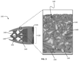
- FIG. 3 shows density changes in the microporous endplate of an implant, according to an exemplary embodiment of the subject disclosure.
- FIG. 4 A-E shows non-uniform and varying strut shapes in an implant, according to an exemplary embodiment of the subject disclosure.
- FIGS. 5 - 12 show various perspectives of a lateral implant, according to an exemplary embodiment of the subject disclosure.
- FIG. 13 shows a perspective view of the frame component of the lateral implant of FIGS. 5 - 11
- FIG. 14 shows an exploded view of the lateral implant of FIGS. 5 - 12 .
- FIGS. 15 - 19 show an alternative exemplary embodiment of a lateral implant of the subject disclosure.
- FIGS. 20 - 25 show an exemplary embodiment of an anterior implant of the subject disclosure.
- FIG. 26 shows an alternative exemplary embodiment of an endplate of an implant of the subject disclosure.
- FIG. 27 shows another alternative exemplary embodiment of an implant of the subject disclosure.
- FIGS. 28 - 29 show another alternative exemplary embodiment of an implant of the subject disclosure.
- FIGS. 30 - 31 shows another alternative exemplary embodiment of an implant of the subject disclosure.
- FIGS. 32 - 33 shows another alternative exemplary embodiment of an implant of the subject disclosure.
- the present disclosure is directed to a spinal fusion implant device 100 having an upper endplate 101 , a lower endplate 102 , a fusion aperture 103 , an instrument engagement feature 104 , including one or more engagement features 105 , such as a tool receiving aperture.
- the instrument engagement feature 104 includes a portion configured to receive at least a portion of a fixation element, such as a fixation plate, a fixation tab or a bone screw.
- the upper endplate 101 and lower endplate 102 have a microporous endplate structure 110 , and the interior portion (or the central body 130 ) of the device 100 , positioned between the upper endplate 101 and lower plate 102 has a macroporous lattice structure body 120 .
- the implant 100 may be constructed from any biocompatible material.
- the implant 100 may be constructed from one single biocompatible material or it may be constructed from several biocompatible materials (e.g., the instrument engagement feature 104 may be a different material than the upper and lower microporous endplates, 101 , 102 ; the macroporous body structure 120 may be a different material than the upper and lower endplates 101 , 102 ; etc.).
- implant 100 is constructed of a titanium alloy and possesses macroporous body lattice structure 120 to help induce bone growth that translates to quicker initial stability within the interspace.
- the macroporous body lattice structure 120 is designed to have inherent flex that helps reduce stress-shielding and subsidence of the implant 100 into the vertebral body of the patient in which it is implanted.
- the spinal fusion implant 100 further comprises a microporous endplate structure 110 formed of a flexible structures which form the bone contacting surface of the implant.
- the flexible structures allow the implant to better conform to the highly variable human vertebral endplate morphology. This ability to conform further adds to the stability of the implant 100 and ability for it to reduce subsidence of the implant into the vertebral bone via better load distribution across the surface of the implant.
- Self-adjusting, flexible structures allow the bone contacting surface of the implant to custom fit the morphology of vertebral body endplates which vary from patient to patient. It is contemplated that the flexible structures could be constructed in additional ways not shown, e.g.
- the spinal fusion implant 100 described herein possesses a number of improvements over conventional systems, including enhanced load distribution and unique endplate-matching and conforming surface. While illustrated in FIGS. 1 - 4 E as an anterior interbody device, size and shape variations of the implant 100 are contemplated to accommodate all surgical approaches to the cervical, thoracic or lumbar regions of the spine, including direct lateral, anterolateral, anterior, posterior and posterolateral approaches (see, for example, FIGS. 28 - 33 ). An interspinous implant 100 with the illustrated features is also possible.
- FIGS. 1 - 4 E illustrate an embodiment wherein the implant 100 is constructed out of a suitable biocompatible material, such as, for example, a titanium alloy, and possesses a macroporous body lattice structure 120 to help induce bone growth that translates to quicker initial stability within the disc interspace.
- the macroporous body lattice structure 120 is designed to have some level of inherent flex that helps reduce stress-shielding and subsidence.
- the upper endplate 101 is contoured to complement the morphology of a vertebral body endplate. Although not shown, another embodiment is contemplated wherein the lower endplate 102 is planar rather than contoured.
- the present disclosure is a spinal fusion implant 100 containing multi-scale lattice features, such as microporous endplate structure 110 and macroporous body lattice structure 120 , that enhance the mechanical properties and radiolucency of, as well as biological responses to, the implant 100 .
- multi-scale lattice features such as microporous endplate structure 110 and macroporous body lattice structure 120 .
- the implant 100 embodies a multi-scale structural design, composed of upper and lower bone contacting surfaces 101 , 102 (or endplates) having a microporous endplate structure 110 , a central body portion 130 between the upper and lower bone contacting surfaces 101 , 102 having a macroporous body lattice structure 120 , and an instrument engagement feature 104 in a trailing end of the implant including tool engagement features 105 .
- Both the microporous endplate structure 110 and the macroporous body lattice structure 120 are comprised of a network of irregularly, and non-uniformly shaped, sized struts of varying thickness 140 .
- This network of struts 140 defines a system of irregularly and non-uniformly shaped and sized non-polygonal pores 150 .
- the scale of the network of struts and corresponding pores is smaller in the microporous endplate structure 110 than the macroporous body lattice structure 120 .
- the exemplary embodiments of the implant 100 include a fusion aperture 103
- alternative embodiments to the ones shown are contemplated not to include a fusion aperture 103 (i.e. the macroporous body lattice encompasses the entire portion of the implant between the microporous endplates).
- spinal fusion implant devices shaped to be implanted into the spine via any known surgical approach to the intervertebral disc space, e.g. direct lateral, anterolateral, anterior, or posterior.
- the general design concept involves the incorporation of the microporous endplate 110 into the upper and lower bone contacting surfaces 101 , 102 as illustrated in FIG. 1 A , which allows continuous porosity throughout the entire implant 100 , i.e. pores formed by the microporous endplate are in communication/contact with the pores formed by the body lattice 120 central body portion 130 .
- This allows bone to integrate uninterrupted into both the micro and macro structures 110 , 120 of the implant 100 .
- the body lattice 120 allows one to tailor and optimize the implant 100 based on patient-specific loading conditions.
- the design parameters may be modulated to exhibit properties similar to bone and promote osseointegration.
- the function of the microporous endplate 110 is to encourage bone growth into the construct immediately following implantation.
- production of the implant 100 is achieved using additive manufacturing techniques, including but not limited to, 3D printing.
- the implant is manufactured using a combination of additive manufacturing and subtractive manufacturing.
- the components of the multi-scale lattice implant 100 include: structural, mechanical, and biological features.
- the implant may be composed of any suitable biocompatible metal, polymeric, and/or ceramic materials.
- the implant 100 may be constructed from one single biocompatible material or it may be constructed from several biocompatible materials (i.e., the instrument engagement feature 104 may be a different material than the upper and lower bone contacting surfaces, 101 , 102 ).
- implant 100 is constructed of a titanium alloy
- FIG. 2 A- 2 C illustrate that the macroporous body lattice 120 may be designed through the use of software including optimization algorithms that tailor the structure based upon loading conditions imparted upon the implant, including: compression, shear, and torsion 111 (see arrows in FIG. 2 B ).
- the micro- and/or body lattice structures 110 , 120 may be functionally-graded with respect to pore size, strut thickness, and/or surface roughness.
- the microporous endplate 110 may be functionally graded in a superior to inferior direction, in a medial to lateral direction, or a combination of superior-to-inferior and medial-to-lateral.
- the porosity of the upper and lower bone contacting surfaces 101 , 102 may be functionally graded to allow for the transition from micro- to macro lattice to be continuous.
- the transition from microporous endplate to macroporous body lattice may be distinct.
- gradation of the stiffness of the microporous endplate would allow the areas in contact with the bone to deflect and deform to better conform to the unique vertebral endplate morphology of an individual patient. This allows for the dual benefit of distributing load and reducing the possibility of subsidence.
- the microporous endplate structure 110 decreases in porosity from the perimeter of the upper and lower bone contacting surfaces 101 , 102 toward the center of the upper and lower bone contacting surfaces 101 , 102 .
- the pore density of the macroporous lattice body structure 120 is increased around the perimeter of the implant 100 , and decreases toward the center of the implant 100 .
- the change in porosity may be gradual, or alternatively the change may be stepwise.
- the microporous endplate structure 110 is tailored to exhibit an elastic modulus less than or equal to the same range as human bone (i.e., between 0.2 GPA and 30 GPa) in order to promote bone growth and reduce stress shielding.
- the bulk elastic modulus of the entire implant 100 is less than or equal to the same range as human bone (0.2 GPa-30 GPa).
- the upper and lower bone contacting surfaces 101 , 102 are tailored to have an elastic modulus that matches or is in the same range as a specific patient's own bone.
- the overall implant is tailored to have an elastic modulus that matches or is in the same range as a specific patient's own bone.
- the implant design software includes optimization algorithms that may be applied to the implant 100 in order to produce a low-density, material efficient implant. This is accomplished by applying multiple, clinically-relevant, loading conditions to the implant 100 in the design program and allowing a finite element solver to optimize and refine the body lattice structure of the implant 100 as seen in FIG. 2 .
- An implant 100 optimized to remove material may benefit a surgeon clinically by increasing the radiolucency of the implant 100 , allowing one to better visualize bone in-growth into the implant 100 .
- the upper and lower bone contacting surfaces 101 , 102 may have regions of different elastic modulus.
- the outer region of the upper and lower bone contacting surfaces 101 , 102 which are in contact with the cortical region of the adjacent vertebral bodies after insertion may have a first elastic modulus while the inner region of the upper and lower bone contacting surfaces 101 , 102 which are in contact with the cancellous region of the adjacent vertebral bodies after insertion have a second elastic modulus.
- the first elastic modulus may is about 6 GPa while the second elastic modulus is about 3 GPa.
- the upper and lower endplates 101 and 102 are formed of microporous endplate structure 110 with a pore 150 size, pore 150 volume, strut 140 thickness, and surface roughness design to promote bone growth and elicit an osteogenic response at the implantation site.
- the pores 150 in the microporous endplate 110 range in diameter from 100 ⁇ m to 1500 ⁇ m
- the strut 140 thicknesses ranges from 100 ⁇ m to 500 ⁇ m.
- the pores 140 in the microporous endplate 110 range in size from 300 ⁇ m to 1200 ⁇ m and the strut 140 thicknesses range in size from 150 ⁇ m to 300 ⁇ m.
- the average pore 150 diameter is 500 ⁇ m and the average strut 140 thickness is 200 ⁇ m.
- the average pore 150 diameter is 800 ⁇ m and the average strut 140 thickness is 200 ⁇ m.
- the microporous endplate structure 110 forming the upper and lower contact surfaces 101 , 102 have an average pore 150 diameter of 500 ⁇ m at the perimeter and transitions to an average pore 150 diameter of 800 ⁇ m toward the center of the upper and lower bone contacting surfaces 101 , 102 . The transition may be gradual or discrete.
- the microporous endplates 101 , 102 have a macro surface roughness comprising protrusions extending up to 300 ⁇ m from the endplate surface and a nano/micro surface roughness comprising a surface texture ranging in depth from 0.45 ⁇ m to 7 ⁇ m.
- the transition from the microporous endplate structure 110 to the macroporous structure 120 may be discrete (i.e., there is no overlap between the structures), a gradient (i.e., the microporous structure 110 average pore 150 size gradually increases to the average pore 150 size found in the macroporous lattice structure 120 ) or there may be some overlap between the structures (i.e., the macroporous lattice structure 120 may extend into the microporous endplate structure 110 ).
- the transition is an overlap wherein the macroporous lattice structure 120 extends into the microporous endplate structure 110 a certain depth, d.
- the depth d of overlap may be varied depending upon the necessary design requirements of a particular implant.
- the overlap between the structures means that depth d is between 5 and 95 percent of the thickness of the microporous endplate structure 110 .
- depth d could range between 5 ⁇ m and 950 ⁇ m.
- depth d is between 25 and 75 percent of the thickness of the microporous structure 110 and in one preferred embodiment, depth d is about 50-66 percent of the thickness of the microporous endplate structure 110 .
- depth d would be about 500-660 ⁇ m.
- the thickness of the microporous endplate structure 110 can vary in different regions of the upper and lower endplates 101 , 102 . In these embodiments, depth d may also change in the regions of varying thickness.
- the depth d could be about 500-660 mm while in an adjacent region of the upper endplate 101 having a microporous structure of 1,500 ⁇ m then depth d could be about 750-1,000 ⁇ m.
- depth d may be constant irrespective of the thickness of the microporous endplate structure 110 or a particular region of the microporous endplate structure 110 .
- the macro porous lattice structure 120 of the central body portion 130 has pores 150 ranging in size from 2 mm to 10 mm in each of the X, Y and Z planes, and the strut 140 thicknesses range in size from 0.3 mm to 5 mm. According to an exemplary embodiment, the pores 150 are about 5.5 mm ⁇ 5.5 mm ⁇ 4 mm with strut 140 thicknesses ranging from 0.5 mm to 2 mm.
- the individual struts 140 comprising the body-lattice structure 120 are non-planar, irregular and not placed according to a regular or repeating pattern. The strut 140 thickness varies throughout the length of the individual strut 140 —in other words, the individual struts 140 have varying thickness across the strut 140 .
- the macroporous lattice body 120 has a surface roughness comprising a surface texture ranging in depth from 0.45 ⁇ m to 7 ⁇ m.
- the individual struts 140 have a greater thickness at each end of the strut 140 , i.e., where the individual strut 140 terminates and/or connects to another individual strut 140 , than in the middle of the strut 140 .
- the minimum and maximum thicknesses of each strut 140 vary from strut to strut.
- the implant 100 may have include a textured surface coating 160 to further encourage bone growth onto the implant 100 .
- the textured surface coating 160 may be a ceramic coating such as calcium phosphate, or a biocompatible metal coating.
- the textured surface coating 160 is applied to the microporous endplate structure 110 .
- the textured surface coating 160 is applied to the macroporous lattice body structure 120 .
- the textured surface coating 160 is applied to the entire implant 100 .
- FIGS. 5 - 14 show various views of an exemplary lateral spinal fusion implant 100 .
- the implant 100 has upper and lower surfaces 101 , 102 formed of a microporous endplate structure 110 and a central body portion 130 formed of a body lattice structure 120 .
- the implant 100 has a leading end 170 and an opposite trailing end 180 , and a fusion aperture 103 extending through the implant 100 from the upper bone contacting surface 101 to the lower bone contacting surface 102 .
- the trailing end 180 includes an instrument engagement feature 104 that includes at least one engagement portion(s) 105 for the engagement of an insertion tool.
- the leading end 170 may be tapered to facilitate insertion into the disc space. In an alternative embodiment, at least a portion of the leading end 170 is solid.
- the length dimension of the implant 100 from leading end 170 to trailing end 180 is in the range from 45 mm to 65 mm
- the anterior to posterior width dimension of the implant 100 is in the range of 18 mm to 26 mm
- angle of lordosis is in the range of 0° to 15°.
- the implant 100 of present disclosure may have a hyperlordotic angle of lordosis ranging from 15° to 40°.
- the spinal fusion implant according to the embodiment in FIGS. 5 - 14 further includes an implant frame 190 .
- the frame 190 may comprise a solid rim bordering the outer perimeter and inner perimeter of the upper and lower contact surfaces 101 , 102 .
- the solid rim along the interior of the upper and lower contact surfaces 101 , 102 forms the boundary of the fusion aperture 103 .
- the implant 100 includes at least one radiopaque marker 200 in the medial plane of the implant 100 . In some embodiments, the implant 100 includes at least 2 radiopaque markers 200 in the medial plane. It is further contemplated that the implant 100 of this disclosure can be used in conjunction with a fixation plate that is coupled to the trailing end 180 of the implant 100 and includes at least one fixation aperture for receiving a fixation element therethrough, such that the fixation aperture lies adjacent the lateral aspect of the vertebral body when the fixation plate is coupled to the implant 100 . In some embodiments, the fixation plate includes two fixation apertures, one that will lie adjacent to the lateral aspect of the superior vertebral body and one that will lie adjacent to the lateral aspect of the inferior vertebral body.
- FIGS. 15 - 19 illustrate an alternative embodiment of a lateral implant, having all the same features as described for FIGS. 10 - 18 , but not including a frame 190 .
- FIGS. 20 - 25 illustrate an exemplary embodiment of an anterior implant 100 dimensioned for insertion into the disc space via an anterior approach.
- the implant 100 of FIGS. 20 - 25 has upper and lower surfaces 101 , 102 formed of a microporous endplate structure 110 and a central body portion 130 formed of a body lattice structure 120 .
- the implant has a leading end 170 and an opposite trailing end 180 , and a fusion aperture 103 extending through the implant 100 from the upper bone contacting surface 101 to the lower bone contacting surface 102 .
- the trailing end 180 includes an instrument engagement feature 104 that includes at least one engagement portion(s) 105 for the engagement of an insert tool.
- the implant 100 has an angle of lordosis in the range of 0° to 15°. It is also contemplated that an exemplary embodiment of a spinal fusion implant of the subject disclosure has a hyperlordotic angle of lordosis ranging from 15° to 40°. According to one exemplary embodiment, the implant 100 includes an implant frame 190 .
- FIGS. 28 - 29 and 32 - 33 illustrate alternative exemplary embodiments of an anterior implant 100 dimensioned for insertion into the disc space via an anterior approach.
- the implant according to this embodiment includes all of the same basic structural features as the implant described above and illustrated in FIGS. 20 - 25 , and further comprises the instrument engagement feature 104 that includes fixation apertures 106 . Although shown as have three apertures in FIGS. 28 - 29 and two apertures in FIGS. 32 - 33 , it is contemplated that the implant has at least 1 fixation aperture. According to these exemplary embodiments, the fixation apertures are dimensioned to receive bone screws.
- the implant does not have a fusion aperture (i.e. the macroporous lattice body is continuous between the microporous endplates, which are also continuous) and/or the implant does not include a frame.
- FIGS. 30 - 31 illustrate another alternative embodiment of a posterior implant dimensioned for insertion into the disc space via a posterior approach.
- the implant according to this embodiment includes all of the same basic structural features as the implants described in FIGS. 1 - 27 , including first and second microporous endplates 101 , 102 , a macroporous lattice body 120 and an instrument engagement feature 104 .
- the implant may be manufactured by separating the implant into separate structures, designing and/or optimizing those structures and combining them for printing in a single build process.
- the implant is designed as two separate structures including the body lattice, and microporous endplates.
- the body lattice structure is optimized to produce an efficient strength-to-weight structure for each implant size manufactured. All implant sizes are optimized to withstand the same loading conditions with a specified maximum allowable lattice stress, resulting in a unique body lattice structure for each implant size.
- each implant component e.g. body lattice, and microporous endplates
- the lattice body structure is optimized (e.g. the thickness of the individual lattice struts is determined as required in order to maximize the strength and minimize the material of the structure) using a finite element analysis and optimization algorithm by applying specific theoretical loading conditions to the implant.
- the design of the microporous endplates is defined to achieve a desired structure and the endplates are combined with the optimized body lattice to produce an assembled device.
- the final device components are exported as a .STL file and prepared to be built with a 3D printing machine.
- the method of manufacturing the implant further includes the step of designing an instrument engagement feature to achieve a desired design, and combining the instrument engagement feature with the microporous endplates and the optimized lattice body before the device components are exported as a .STL file and prepared to be built with a 3D printing machine.
- additional features such as apertures, are machined into the instrument engagement feature after the device has been printed.
- the method of manufacturing the implant further includes the step of designing a rim to achieve a desired structure, combining it with the microporous endplates and the optimized lattice body, with or without the instrument engagement feature, exporting the final device components as a .STL file and preparing to build the implant with a 3D printing machine.
- the specification may have presented the method and/or process of the present subject disclosure as a particular sequence of steps. However, to the extent that the method or process does not rely on the particular order of steps set forth herein, the method or process should not be limited to the particular sequence of steps described. As one of ordinary skill in the art would appreciate, other sequences of steps may be possible. Therefore, the particular order of the steps set forth in the specification should not be construed as limitations on the claims. In addition, the claims directed to the method and/or process of the present subject disclosure should not be limited to the performance of their steps in the order written, and one skilled in the art can readily appreciate that the sequences may be varied and still remain within the spirit and scope of the present subject disclosure.
Abstract
Description
Claims (20)
Priority Applications (2)
| Application Number | Priority Date | Filing Date | Title |
|---|---|---|---|
| US16/866,713 US11660203B2 (en) | 2015-12-16 | 2020-05-05 | Porous spinal fusion implant |
| US18/297,747 US20230240858A1 (en) | 2015-12-16 | 2023-04-10 | Porous spinal fusion implant |
Applications Claiming Priority (6)
| Application Number | Priority Date | Filing Date | Title |
|---|---|---|---|
| US201562268430P | 2015-12-16 | 2015-12-16 | |
| US201662354077P | 2016-06-23 | 2016-06-23 | |
| US201662379988P | 2016-08-26 | 2016-08-26 | |
| PCT/US2016/067371 WO2017106780A1 (en) | 2015-12-16 | 2016-12-16 | Porous spinal fusion implant |
| US16/010,405 US10675158B2 (en) | 2015-12-16 | 2018-06-16 | Porous spinal fusion implant |
| US16/866,713 US11660203B2 (en) | 2015-12-16 | 2020-05-05 | Porous spinal fusion implant |
Related Parent Applications (1)
| Application Number | Title | Priority Date | Filing Date |
|---|---|---|---|
| US16/010,405 Continuation US10675158B2 (en) | 2015-12-16 | 2018-06-16 | Porous spinal fusion implant |
Related Child Applications (1)
| Application Number | Title | Priority Date | Filing Date |
|---|---|---|---|
| US18/297,747 Continuation US20230240858A1 (en) | 2015-12-16 | 2023-04-10 | Porous spinal fusion implant |
Publications (2)
| Publication Number | Publication Date |
|---|---|
| US20200261243A1 US20200261243A1 (en) | 2020-08-20 |
| US11660203B2 true US11660203B2 (en) | 2023-05-30 |
Family
ID=57737999
Family Applications (3)
| Application Number | Title | Priority Date | Filing Date |
|---|---|---|---|
| US16/010,405 Active US10675158B2 (en) | 2015-12-16 | 2018-06-16 | Porous spinal fusion implant |
| US16/866,713 Active 2037-09-19 US11660203B2 (en) | 2015-12-16 | 2020-05-05 | Porous spinal fusion implant |
| US18/297,747 Pending US20230240858A1 (en) | 2015-12-16 | 2023-04-10 | Porous spinal fusion implant |
Family Applications Before (1)
| Application Number | Title | Priority Date | Filing Date |
|---|---|---|---|
| US16/010,405 Active US10675158B2 (en) | 2015-12-16 | 2018-06-16 | Porous spinal fusion implant |
Family Applications After (1)
| Application Number | Title | Priority Date | Filing Date |
|---|---|---|---|
| US18/297,747 Pending US20230240858A1 (en) | 2015-12-16 | 2023-04-10 | Porous spinal fusion implant |
Country Status (8)
| Country | Link |
|---|---|
| US (3) | US10675158B2 (en) |
| EP (1) | EP3389570B1 (en) |
| JP (3) | JP2018537235A (en) |
| KR (1) | KR20180095853A (en) |
| CN (2) | CN112842636A (en) |
| AU (3) | AU2016369593B2 (en) |
| BR (1) | BR112018012191B1 (en) |
| WO (1) | WO2017106780A1 (en) |
Families Citing this family (75)
| Publication number | Priority date | Publication date | Assignee | Title |
|---|---|---|---|---|
| US20180228621A1 (en) | 2004-08-09 | 2018-08-16 | Mark A. Reiley | Apparatus, systems, and methods for the fixation or fusion of bone |
| US9265620B2 (en) | 2011-03-18 | 2016-02-23 | Raed M. Ali, M.D., Inc. | Devices and methods for transpedicular stabilization of the spine |
| US10363140B2 (en) | 2012-03-09 | 2019-07-30 | Si-Bone Inc. | Systems, device, and methods for joint fusion |
| EP2967909A4 (en) | 2013-03-14 | 2016-10-05 | Raed M Ali M D Inc | Lateral interbody fusion devices, systems and methods |
| US10687962B2 (en) | 2013-03-14 | 2020-06-23 | Raed M. Ali, M.D., Inc. | Interbody fusion devices, systems and methods |
| US11147688B2 (en) | 2013-10-15 | 2021-10-19 | Si-Bone Inc. | Implant placement |
| KR20170043110A (en) * | 2014-08-14 | 2017-04-20 | 오에스에스디자인 아베 | Bone implants for correcting bone defects |
| JP6542362B2 (en) * | 2014-09-18 | 2019-07-10 | エスアイ−ボーン・インコーポレイテッドSi−Bone, Inc. | Matrix implant |
| US10449051B2 (en) | 2015-04-29 | 2019-10-22 | Institute for Musculoskeletal Science and Education, Ltd. | Implant with curved bone contacting elements |
| EP3760166A1 (en) | 2015-04-29 | 2021-01-06 | Institute For Musculoskeletal Science And Education, Ltd. | Coiled implants and systems |
| US10898332B2 (en) | 2015-11-24 | 2021-01-26 | Ossdsign Ab | Bone implants and methods for correcting bone defects |
| WO2017106780A1 (en) | 2015-12-16 | 2017-06-22 | Nuvasive, Inc. | Porous spinal fusion implant |
| US11638645B2 (en) | 2016-05-19 | 2023-05-02 | University of Pittsburgh—of the Commonwealth System of Higher Education | Biomimetic plywood motifs for bone tissue engineering |
| WO2017201371A1 (en) * | 2016-05-19 | 2017-11-23 | University Of Pittsburgh-Of The Commonwealth System Of Higher Education | Biomimetic plywood motifs for bone tissue engineering |
| US20200000595A1 (en) | 2016-06-07 | 2020-01-02 | HD LifeSciences LLC | High X-Ray Lucency Lattice Structures |
| US10660764B2 (en) * | 2016-06-14 | 2020-05-26 | The Trustees Of The Stevens Institute Of Technology | Load sustaining bone scaffolds for spinal fusion utilizing hyperbolic struts and translational strength gradients |
| US11033394B2 (en) | 2016-10-25 | 2021-06-15 | Institute for Musculoskeletal Science and Education, Ltd. | Implant with multi-layer bone interfacing lattice |
| US10478312B2 (en) | 2016-10-25 | 2019-11-19 | Institute for Musculoskeletal Science and Education, Ltd. | Implant with protected fusion zones |
| US11253368B2 (en) | 2017-02-14 | 2022-02-22 | Nanohive Medical Llc | Methods of designing high x-ray lucency lattice structures |
| US10512549B2 (en) | 2017-03-13 | 2019-12-24 | Institute for Musculoskeletal Science and Education, Ltd. | Implant with structural members arranged around a ring |
| US10357377B2 (en) | 2017-03-13 | 2019-07-23 | Institute for Musculoskeletal Science and Education, Ltd. | Implant with bone contacting elements having helical and undulating planar geometries |
| US10888429B2 (en) | 2017-04-01 | 2021-01-12 | HD LifeSciences LLC | Three-dimensional lattice structures for implants |
| CA3049692C (en) * | 2017-05-04 | 2022-08-30 | Wright Medical Technology, Inc. | Bone implant with struts |
| KR101977065B1 (en) * | 2017-09-01 | 2019-05-13 | 건양대학교 산학협력단 | Intervertebral Fusion Implant of Porous Structure |
| US11116519B2 (en) | 2017-09-26 | 2021-09-14 | Si-Bone Inc. | Systems and methods for decorticating the sacroiliac joint |
| AU2018351068A1 (en) * | 2017-10-20 | 2020-05-28 | Centinel Spine, Llc | Porous implantable interbody devices |
| US10744001B2 (en) | 2017-11-21 | 2020-08-18 | Institute for Musculoskeletal Science and Education, Ltd. | Implant with improved bone contact |
| US10940015B2 (en) | 2017-11-21 | 2021-03-09 | Institute for Musculoskeletal Science and Education, Ltd. | Implant with improved flow characteristics |
| JP2019180797A (en) * | 2018-04-09 | 2019-10-24 | 日本特殊陶業株式会社 | Vertebral body spacer |
| CN108814773B (en) * | 2018-04-24 | 2021-01-08 | 上海科太迈迪医疗器械有限公司 | Generation method of three-dimensional model of acetabular cup bone trabecula structure and related components |
| US10555819B2 (en) * | 2018-05-08 | 2020-02-11 | Globus Medical, Inc. | Intervertebral spinal implant |
| CN111529144B (en) * | 2018-06-12 | 2022-11-15 | 深圳市立心科学有限公司 | Self-adaptive intervertebral fusion device |
| CN108670507B (en) * | 2018-06-12 | 2021-01-15 | 深圳市立心科学有限公司 | Self-adaptive intervertebral fusion device |
| CN213722665U (en) * | 2018-06-12 | 2021-07-20 | 深圳市立心科学有限公司 | Intervertebral fusion device with multiple buffering parts |
| US11291558B2 (en) | 2018-07-26 | 2022-04-05 | Nanohive Medical Llc | Dynamic implant fixation plate |
| EP3603580B1 (en) * | 2018-08-02 | 2023-12-06 | Globus Medical, Inc. | Intervertebral spinal implants |
| CA3108768C (en) * | 2018-08-07 | 2022-05-10 | Minimally Invasive Spinal Technology, LLC | Device and method for correcting spinal deformities in patients |
| AU2019213392A1 (en) * | 2018-08-09 | 2020-02-27 | Stryker European Operations Holdings, LLC | Interbody implants and optimization features thereof |
| US10299938B1 (en) | 2018-09-07 | 2019-05-28 | John R. Ehteshami | Dynamic intervertebral spacer implant |
| US11234838B2 (en) | 2018-09-07 | 2022-02-01 | Additive Implants, Inc. | Dynamic intervertebral spacer implant |
| WO2020069202A1 (en) * | 2018-09-27 | 2020-04-02 | Tdbt Ip Inc. | Spinal disc replacements and methods of making thereof |
| KR102196502B1 (en) * | 2018-10-11 | 2020-12-30 | 건양대학교 산학협력단 | Cervical Stand-Alone Cage with Porous Structure |
| WO2020085321A1 (en) * | 2018-10-23 | 2020-04-30 | 国立大学法人大阪大学 | Implant material and method for producing said implant material |
| US20210145596A1 (en) * | 2018-12-04 | 2021-05-20 | Beijing Chunlizhengda Medical Instruments Co., Ltd | Toe joint prosthesis and manufacturing method therefor |
| JP2020096830A (en) | 2018-12-05 | 2020-06-25 | スメド−ティーエイ/ティーディー・エルエルシー | Adjusted-stiffness orthopaedic implants and method of manufacture |
| US11179247B2 (en) | 2018-12-12 | 2021-11-23 | Zimmer Biomet Spine, Inc. | Intervertebral implants |
| US11684482B2 (en) | 2018-12-20 | 2023-06-27 | Additive Implants, Inc. | Spondylolisthesis system and methods |
| US11497617B2 (en) | 2019-01-16 | 2022-11-15 | Nanohive Medical Llc | Variable depth implants |
| EP3923829A4 (en) | 2019-02-14 | 2022-12-14 | SI-Bone, Inc. | Implants for spinal fixation and or fusion |
| US11369419B2 (en) | 2019-02-14 | 2022-06-28 | Si-Bone Inc. | Implants for spinal fixation and or fusion |
| KR102226568B1 (en) * | 2019-02-19 | 2021-03-11 | 주식회사 비트러스트메디텍 | Porous Spinal Cage with Minimized Solid Part |
| US20220362027A1 (en) | 2019-03-13 | 2022-11-17 | National University Of Singapore | An orthopaedic trauma plate and method for forming same |
| CN109966027B (en) * | 2019-04-28 | 2021-02-19 | 华南协同创新研究院 | Gradient unit for bone repair, porous scaffold and preparation method |
| US11173043B1 (en) | 2019-05-17 | 2021-11-16 | Joseph T. Robbins | Spinal interbody implants |
| CN110368147A (en) * | 2019-08-05 | 2019-10-25 | 北京爱康宜诚医疗器材有限公司 | Invasive lumbar fusion device and preparation method thereof |
| CN114845669A (en) * | 2019-09-20 | 2022-08-02 | 比肯生物医疗有限公司 | Spinal implant with surface protrusions |
| AU2020354354A1 (en) * | 2019-09-24 | 2022-04-14 | Additive Implants, Inc. | Dynamic intervertebral spacer implant |
| US11123201B2 (en) | 2019-09-24 | 2021-09-21 | Additive Implants, Inc. | Intervertebral spacer |
| WO2021061205A1 (en) * | 2019-09-25 | 2021-04-01 | Mirus, Llc | Interbody lattice structure |
| US11672570B2 (en) | 2019-11-27 | 2023-06-13 | Si-Bone Inc. | Bone stabilizing implants and methods of placement across SI Joints |
| US11707361B2 (en) | 2020-02-05 | 2023-07-25 | K2M, Inc. | Flexible interbody implant |
| KR102151554B1 (en) * | 2020-05-19 | 2020-09-03 | (주)칼리스토 | 3D printing intervertebral cage of dynamic stabilization |
| EP4161450A1 (en) * | 2020-06-05 | 2023-04-12 | NuVasive, Inc. | Dynamic interbody fusion devices |
| IT202000014569A1 (en) * | 2020-06-18 | 2021-12-18 | Sps S R L | INTERSOMATIC CAGE FOR VERTEBRAL STABILIZATION |
| EP4228556A1 (en) * | 2020-10-14 | 2023-08-23 | K2M, Inc. | Spinal interbody implants |
| US20220117753A1 (en) * | 2020-10-16 | 2022-04-21 | KYOCERA Medical Technologies, Inc. | Surgical implant device incorporating a lattice volume and associated method of manufacture |
| USD942624S1 (en) | 2020-11-13 | 2022-02-01 | Mirus Llc | Spinal implant |
| USD944400S1 (en) | 2020-11-13 | 2022-02-22 | Mirus Llc | Spinal implant |
| USD942623S1 (en) | 2020-11-13 | 2022-02-01 | Mirus Llc | Spinal implant |
| USD942011S1 (en) | 2020-11-13 | 2022-01-25 | Mirus Llc | Spinal implant |
| EP4259015A1 (en) | 2020-12-09 | 2023-10-18 | SI-Bone, Inc. | Sacro-iliac joint stabilizing implants and methods of implantation |
| GB2602821A (en) * | 2021-01-15 | 2022-07-20 | Osstec Ltd | Orthopaedic implant |
| US11744711B2 (en) | 2021-03-22 | 2023-09-05 | Orthofix Us Llc | Spinal interbody devices with density gradients and associated methods |
| EP4337145A1 (en) | 2021-05-14 | 2024-03-20 | Nuvasive, Inc. | Inserter for spinal fusion implant |
| KR102600160B1 (en) * | 2021-08-26 | 2023-11-08 | 주식회사 코렌텍 | Intervertebral Body Fusion Prosthesis With Porous Structure of Shell Type |
Citations (200)
| Publication number | Priority date | Publication date | Assignee | Title |
|---|---|---|---|---|
| US4820305A (en) | 1986-11-03 | 1989-04-11 | Harms Juergen | Place holder, in particular for a vertebra body |
| US5108435A (en) | 1989-09-28 | 1992-04-28 | Pfizer Hospital Products Group, Inc. | Cast bone ingrowth surface |
| US5147402A (en) | 1990-12-05 | 1992-09-15 | Sulzer Brothers Limited | Implant for ingrowth of osseous tissue |
| EP0599419A2 (en) | 1992-11-26 | 1994-06-01 | ESKA Implants GmbH & Co. | Disk-shaped implant for reinforcing adjacent vertebrae |
| WO1995001763A1 (en) | 1993-07-09 | 1995-01-19 | Lutz Biedermann | Spacer, in particular for an intervertebral disk |
| US5534028A (en) | 1993-04-20 | 1996-07-09 | Howmedica, Inc. | Hydrogel intervertebral disc nucleus with diminished lateral bulging |
| US5628630A (en) | 1994-12-15 | 1997-05-13 | Univ. Of Alabama At Birmingham | Design process for skeletal implants to optimize cellular response |
| US5702451A (en) | 1995-02-14 | 1997-12-30 | Biedermann; Lutz | Space holder, in particular for a vertebra or an intervertebral disk |
| WO1998052498A1 (en) | 1997-05-23 | 1998-11-26 | Volkmar Jansson | Replacement structures for bones and cartilage |
| USD403069S (en) | 1997-06-02 | 1998-12-22 | Sdgi Holdings, Inc. | Orthopedic bone support |
| US5897556A (en) | 1997-06-02 | 1999-04-27 | Sdgi Holdings, Inc. | Device for supporting weak bony structures |
| WO1999063914A1 (en) | 1998-06-09 | 1999-12-16 | Henderson Fraser C | Fusion stabilization chamber |
| CN1267068A (en) | 1999-03-11 | 2000-09-20 | 株式会社村田制作所 | Method for calcining magnetic core |
| US6206924B1 (en) | 1999-10-20 | 2001-03-27 | Interpore Cross Internat | Three-dimensional geometric bio-compatible porous engineered structure for use as a bone mass replacement or fusion augmentation device |
| US20020130112A1 (en) | 2000-06-05 | 2002-09-19 | Mark Manasas | Orthopedic implant and method of making metal articles |
| US6491626B1 (en) | 1999-04-16 | 2002-12-10 | Nuvasive | Articulation systems for positioning minimally invasive surgical tools |
| WO2003007841A2 (en) | 2001-07-10 | 2003-01-30 | Vitatech | Intervertebral implant for cervical vertebrae |
| US6520997B1 (en) | 1999-12-08 | 2003-02-18 | Baxter International Inc. | Porous three dimensional structure |
| US6530958B1 (en) | 1993-10-18 | 2003-03-11 | Massachusetts Institute Of Technology | Tissue regeneration matrices by solid free-form fabrication techniques |
| EP1315968A2 (en) | 2000-09-05 | 2003-06-04 | Zeptosens AG | Method for precipitating mono and multiple layers of organophosphoric and organophosphonic acids and the salts thereof in addition to use thereof |
| US6585770B1 (en) | 1997-06-02 | 2003-07-01 | Sdgi Holdings, Inc. | Devices for supporting bony structures |
| US20030181979A1 (en) | 2002-01-23 | 2003-09-25 | Ferree Bret A. | Bone reinforcers |
| US6696073B2 (en) | 1999-02-23 | 2004-02-24 | Osteotech, Inc. | Shaped load-bearing osteoimplant and methods of making same |
| EP1418013A1 (en) | 2002-11-08 | 2004-05-12 | Howmedica Osteonics Corp. | Laser-produced porous surface |
| US20040172019A1 (en) | 1999-10-08 | 2004-09-02 | Ferree Bret A. | Reinforcers for artificial disc replacement methods and apparatus |
| US20040220672A1 (en) | 2003-05-03 | 2004-11-04 | Shadduck John H. | Orthopedic implants, methods of use and methods of fabrication |
| WO2004098456A2 (en) | 2003-05-01 | 2004-11-18 | Therics, Inc. | Porous biostructure partially occupied by interpenetrant and method for making same |
| JP2004537370A (en) | 2001-08-11 | 2004-12-16 | スタンモア インプランツ ワールドワイド リミティッド | Surgical implant |
| US20040265385A1 (en) | 2001-04-12 | 2004-12-30 | Therics, Inc. | Porous biostructure partially occupied by interpenetrant and method for making same |
| US20050015154A1 (en) | 2003-06-25 | 2005-01-20 | Baylor College Of Medicine Office Of Technology Administration | Tissue integration design for seamless implant fixation |
| US20050065613A1 (en) | 2003-09-24 | 2005-03-24 | Gross Jeffrey M. | Reinforced fusion implant |
| WO2005037137A2 (en) | 2003-10-17 | 2005-04-28 | Therics, Inc. | Spinal cage insert, filler piece and method of manufacturing |
| US20050112397A1 (en) | 2003-07-24 | 2005-05-26 | Rolfe Jonathan L. | Assembled non-random foams |
| WO2005051233A2 (en) | 2003-11-21 | 2005-06-09 | William Marsh Rice University | Computer-aided tissue engineering of a biological body |
| US20050165482A1 (en) | 2002-06-26 | 2005-07-28 | Jorg Goldhahn | Bone fixation element |
| US20050177238A1 (en) * | 2001-05-01 | 2005-08-11 | Khandkar Ashok C. | Radiolucent bone graft |
| US6942830B2 (en) | 2000-04-17 | 2005-09-13 | Envisiontec Gmbh | Device and method for the production of three-dimensional objects |
| US6989033B1 (en) | 1992-09-17 | 2006-01-24 | Karlheinz Schmidt | Implant for recreating verterbrae and tubular bones |
| US20060129240A1 (en) | 2004-12-10 | 2006-06-15 | Joe Lessar | Implants based on engineered composite materials having enhanced imaging and wear resistance |
| US20060141012A1 (en) | 2004-11-09 | 2006-06-29 | Peter Gingras | Tissue scaffold |
| US20060147332A1 (en) | 2004-12-30 | 2006-07-06 | Howmedica Osteonics Corp. | Laser-produced porous structure |
| US20060167550A1 (en) | 2002-10-08 | 2006-07-27 | Robert Snell | High precision manufacture of polyurethane products such as spinal disc implants having a gradual modulus variation |
| US7105023B2 (en) | 2002-01-17 | 2006-09-12 | Concept Matrix, L.L.C. | Vertebral defect device |
| US20060212158A1 (en) | 2004-12-23 | 2006-09-21 | Robert Miller | System for manufacturing an implant |
| WO2006109137A1 (en) | 2005-04-12 | 2006-10-19 | Sureshan Sivananthan | Tissue regeneration by endocultivation |
| US20060247769A1 (en) | 2005-04-28 | 2006-11-02 | Sdgi Holdings, Inc. | Polycrystalline diamond compact surfaces on facet arthroplasty devices |
| US20060276925A1 (en) | 2003-04-23 | 2006-12-07 | The Regents Of The University Of Michigan | Integrated global layout and local microstructure topology optimization approach for spinal cage design and fabrication |
| US7153325B2 (en) | 2003-08-01 | 2006-12-26 | Ultra-Kinetics, Inc. | Prosthetic intervertebral disc and methods for using the same |
| US20070027544A1 (en) | 2005-07-28 | 2007-02-01 | Altiva Corporation | Spinal cage implant |
| US20070083266A1 (en) | 2001-05-25 | 2007-04-12 | Vertegen, Inc. | Devices and methods for treating facet joints, uncovertebral joints, costovertebral joints and other joints |
| US20070118243A1 (en) | 2005-10-14 | 2007-05-24 | Vantus Technology Corporation | Personal fit medical implants and orthopedic surgical instruments and methods for making |
| US20070179610A1 (en) | 2005-12-23 | 2007-08-02 | Lutz Biedermann | Multi-walled placeholder |
| US7270679B2 (en) | 2003-05-30 | 2007-09-18 | Warsaw Orthopedic, Inc. | Implants based on engineered metal matrix composite materials having enhanced imaging and wear resistance |
| US20070233269A1 (en) | 2001-05-25 | 2007-10-04 | Conformis, Inc. | Interpositional Joint Implant |
| US20070233272A1 (en) | 1999-02-23 | 2007-10-04 | Boyce Todd M | Shaped load-bearing osteoimplant and methods of making same |
| US20070270969A1 (en) | 2006-05-17 | 2007-11-22 | Schmid Steven R | Welded-woven materials |
| US20070276492A1 (en) | 2006-05-09 | 2007-11-29 | Ranier Limited | Artificial spinal disc implant |
| WO2008040409A1 (en) | 2006-09-29 | 2008-04-10 | Aesculap Ag & Co. Kg | Augmentation component for filling in bone defects |
| US20080114454A1 (en) | 2006-11-10 | 2008-05-15 | Warsaw Orthopedic, Inc. | Expandable Vertebral Body Implants Including Shape-Memory Materials and Methods of Use |
| US20080195211A1 (en) | 2006-10-30 | 2008-08-14 | Chia-Ying Lin | Engineered Scaffolds for Intervertebral Disc Repair and Regeneration and for Articulating Joint Repair and Regeneration |
| WO2008101090A2 (en) | 2007-02-14 | 2008-08-21 | Conformis, Inc. | Implant device and method for manufacture |
| CN100434049C (en) | 2005-03-14 | 2008-11-19 | 西安交通大学 | Double-layered bionic pseudo-structure of cervical intervertebral disci, and its mfg. process |
| US20090043398A1 (en) * | 2007-08-09 | 2009-02-12 | Zimmer, Inc. | Method of producing gradient articles by centrifugation molding or casting |
| US7507253B2 (en) | 2003-10-22 | 2009-03-24 | Nordquist William D | Implantable brace for a fracture and methods |
| CN101416906A (en) | 2008-11-26 | 2009-04-29 | 北京天新福医疗器材有限公司 | Preparation method and use of medical metal artificial bone trabecula |
| CN101418392A (en) | 2008-12-08 | 2009-04-29 | 大连交通大学 | Bio-medical porous titanium products and preparation method thereof |
| US7537616B1 (en) | 1999-10-20 | 2009-05-26 | Warsaw Orthopedic, Inc. | Impacted orthopedic bone support implant |
| US20090222103A1 (en) | 2001-05-25 | 2009-09-03 | Conformis, Inc. | Articular Implants Providing Lower Adjacent Cartilage Wear |
| US20090222098A1 (en) | 2008-02-28 | 2009-09-03 | Warsaw Orthopedics, Inc. | Spinal nucleus replacement with varying modulus |
| US20090276045A1 (en) | 2001-05-25 | 2009-11-05 | Conformis, Inc. | Devices and Methods for Treatment of Facet and Other Joints |
| US20100094292A1 (en) | 2008-10-14 | 2010-04-15 | Zimmer, Inc. | Modular intramedullary nail |
| US20100137990A1 (en) | 2007-02-20 | 2010-06-03 | National University Of Ireland, Galway | Porous Substrates for Implantation |
| CN201529176U (en) | 2009-11-17 | 2010-07-21 | 北京天新福医疗器材有限公司 | Embedded bone trabecula intervertebral fusion device used for anastomosing vertebra |
| US20100217270A1 (en) | 2009-02-25 | 2010-08-26 | Conformis, Inc. | Integrated Production of Patient-Specific Implants and Instrumentation |
| US20110015741A1 (en) | 2009-07-16 | 2011-01-20 | Warsaw Orthopedic, Inc. | Spinal implant configured to apply radiation treatment and method |
| US20110015743A1 (en) | 2009-07-14 | 2011-01-20 | Doctors Research Group, Inc. | Multi-density polymeric interbody spacer |
| US20110022180A1 (en) | 2009-07-24 | 2011-01-27 | Warsaw Orthopedic, Inc. | Implantable medical devices |
| WO2011028236A1 (en) | 2009-08-27 | 2011-03-10 | Cardinal Spine, Llc | Spinal implant |
| US20110071635A1 (en) | 2009-09-23 | 2011-03-24 | Zimmer Spine, Inc. | Composite implant |
| US20110076316A1 (en) | 2007-10-08 | 2011-03-31 | Sureshan Sivananthan | Scalable matrix for the in vivo cultivation of bone and cartilage |
| EP2308423A1 (en) | 2003-04-16 | 2011-04-13 | Howmedica Osteonics Corp. | Craniofacial implant |
| US20110125284A1 (en) | 2008-05-28 | 2011-05-26 | University Of Bath | Improvements in or Relating to Joints and/or Implants |
| US20110144752A1 (en) | 2008-08-14 | 2011-06-16 | Defelice Scott F | Customized implants for bone replacement |
| US20110166659A1 (en) | 2008-07-04 | 2011-07-07 | Dr. H.C. Robert Mathys Stiftung | Implant Device |
| FR2955025A1 (en) | 2010-01-11 | 2011-07-15 | Kasios | Biocompatible metal piece i.e. titanium piece, for e.g. hip prosthesis implanted in human body, has passages arranged such that radiation traverses piece in three directions, where piece is partially in form of lattice when viewed from top |
| US20110190888A1 (en) * | 2010-02-01 | 2011-08-04 | Bertele Theodore P | Composite Interbody Device And Method of Manufacture |
| US20110224796A1 (en) | 2008-11-07 | 2011-09-15 | Advanced Medical Technologies Ag | Implant for fusing spinal column segments |
| WO2011130812A2 (en) | 2010-04-06 | 2011-10-27 | Fundação Universidade Federal De São Carlos | Suspensions for preparing biosilicate-based bone grafts (scaffolds), thus obtained bone grafts and methods for producing same |
| US20110282392A1 (en) | 2006-10-30 | 2011-11-17 | Tissue Regeneration Systems, Inc. | Degradable cage for bone fusion |
| US8062365B2 (en) | 2003-08-04 | 2011-11-22 | Warsaw Orthopedic, Inc. | Bone supporting devices with bio-absorbable end members |
| US20110301709A1 (en) | 2010-06-03 | 2011-12-08 | Kilian Kraus | Intervertebral implant |
| US20110313532A1 (en) | 2010-06-18 | 2011-12-22 | Jessee Hunt | Bone implant interface system and method |
| CN102293693A (en) | 2011-06-01 | 2011-12-28 | 中国人民解放军第四军医大学 | Porous titanium alloy human cervical interbody fusion cage with bioactivity and preparation method thereof |
| CN102440852A (en) | 2011-12-07 | 2012-05-09 | 上海交通大学 | Mixed porous structure interbody fusion cage and preparation method thereof |
| WO2012072111A1 (en) | 2010-11-30 | 2012-06-07 | Smith & Nephew Orthopaedics Ag | Orthopaedic implant |
| US20120150299A1 (en) * | 2010-06-10 | 2012-06-14 | Ergun Asli | Integrated multi-zonal cage/core implants as bone graft substitutes and apparatus and method for their fabrication |
| US20120179271A1 (en) | 2011-01-12 | 2012-07-12 | Bio2 Technologies, Inc. | Devices and Methods for Tissue Engineering |
| US20120191188A1 (en) | 2011-01-20 | 2012-07-26 | Huang meng-feng | Spinal implant with bone engaging projections |
| US8246683B2 (en) | 2005-03-24 | 2012-08-21 | Cardinal Spine, Llc | Spinal implant |
| US20120232654A1 (en) | 2009-08-19 | 2012-09-13 | Smith & Nephew, Inc. | Porous implant structures |
| US8266780B2 (en) | 2005-04-21 | 2012-09-18 | Biomet Manufacturing Corp. | Method and apparatus for use of porous implants |
| US20120271418A1 (en) | 2011-02-28 | 2012-10-25 | Tissue Regeneration Systems, Inc. | Modular tissue scaffolds |
| JP2012232023A (en) | 2011-05-06 | 2012-11-29 | Osaka Univ | Porous artificial bone |
| US20120321878A1 (en) | 2009-11-12 | 2012-12-20 | Landon Ryan L | Controlled randomized porous structures and methods for making same |
| US8343230B2 (en) | 2005-09-22 | 2013-01-01 | Depuy Products, Inc. | Orthopaedic bearing material |
| WO2013006778A2 (en) | 2011-07-07 | 2013-01-10 | 4-Web, Inc. | Foot and ankle implant system and method |
| US20130030529A1 (en) | 2011-07-29 | 2013-01-31 | Jessee Hunt | Implant interface system and method |
| US20130030540A1 (en) | 2011-07-26 | 2013-01-31 | Rita Leibinger GmbH & Co., KG | Tibia implant for tightening the patella tendons |
| US20130084543A1 (en) | 2011-10-03 | 2013-04-04 | Technische Universitat Wien | Thiol-ene polymerization with vinylesters and vinylcarbonate |
| US8430930B2 (en) | 2008-12-18 | 2013-04-30 | 4-Web, Inc. | Truss implant |
| WO2013060168A1 (en) | 2011-10-24 | 2013-05-02 | 北京爱康宜诚医疗器材股份有限公司 | Fusion prosthesis |
| US20130110248A1 (en) | 2011-11-02 | 2013-05-02 | Arthrodisc, L.L.C. | Lockable implant members |
| US20130116793A1 (en) | 2010-07-23 | 2013-05-09 | Privelop-Spine Ag | Surgical implant |
| US20130123935A1 (en) | 2011-11-03 | 2013-05-16 | Jessee Hunt | Method of length preservation during bone repair |
| US8454705B2 (en) | 2007-05-29 | 2013-06-04 | Limacorporate Spa | Prosthetic element and relative method to make it |
| US20130150967A1 (en) | 2011-12-09 | 2013-06-13 | Metal Industries Research & Development Centre | Interbody Cage for Spine Fusion |
| CN103171153A (en) | 2013-04-17 | 2013-06-26 | 新疆大学 | Process method for pneumatically extruding, depositing and molding porous biological bone scaffold |
| EP2606859A1 (en) | 2011-12-23 | 2013-06-26 | Asociación Centro de Investigación en Tecnologias de Union Lortek | Osseointegrable implant for cervical corpectomy |
| JP3184817U (en) | 2012-05-30 | 2013-07-18 | 合碩生技股▲分▼有限公司 | Medical implant material with hollow network structure |
| US20130211533A1 (en) | 2012-02-09 | 2013-08-15 | Mx Orthopedics, Corp. | Porous coating for orthopedic implant utilizing porous, shape memory materials |
| US20130218282A1 (en) | 2012-02-08 | 2013-08-22 | Jessee Hunt | Prosthetic implant for ball and socket joints and method of use |
| US8545559B2 (en) | 2007-10-05 | 2013-10-01 | Washington State University | Modified metal materials, surface modifications to improve cell interactions and antimicrobial properties, and methods for modifying metal surface properties |
| US8551173B2 (en) | 2008-01-17 | 2013-10-08 | DePuy Synthes Products, LLC | Expandable intervertebral implant and associated method of manufacturing the same |
| US8556971B2 (en) | 2001-05-25 | 2013-10-15 | Conformis, Inc. | Joint arthroplasty devices formed in situ |
| US8556983B2 (en) | 2001-05-25 | 2013-10-15 | Conformis, Inc. | Patient-adapted and improved orthopedic implants, designs and related tools |
| US20130274885A1 (en) | 2010-11-10 | 2013-10-17 | Mitsubishi Materials Corporation | Vertebral body spacer |
| US20130325142A1 (en) | 2012-05-31 | 2013-12-05 | Zimmer, Inc. | Anisotropic porous scaffolds |
| CN203341867U (en) | 2013-07-23 | 2013-12-18 | 林杨 | Individual intervertebral disc artificial nucleus prosthesis manufacturing device |
| US8623090B2 (en) | 2007-04-18 | 2014-01-07 | Life Spine, Inc. | Spinal disc prostheses |
| US20140058517A1 (en) | 2012-08-27 | 2014-02-27 | Anthony Sabatino | Auxetic prosthetic implant |
| WO2014039429A1 (en) | 2012-09-04 | 2014-03-13 | Anthrogenesis Corporation | Methods of tissue generation |
| WO2014039427A1 (en) | 2012-09-04 | 2014-03-13 | Anthrogenesis Corporation | Methods of tissue generation |
| US8682052B2 (en) | 2008-03-05 | 2014-03-25 | Conformis, Inc. | Implants for altering wear patterns of articular surfaces |
| US20140088716A1 (en) | 2012-09-21 | 2014-03-27 | Zimmer, Inc. | Variable density implant and method |
| CN103690278A (en) | 2013-12-16 | 2014-04-02 | 深圳市第二人民医院 | 3D (three-dimensional) printing technology-based preparation method for personalized bionic vertebral column system |
| US8697231B2 (en) | 2009-09-09 | 2014-04-15 | Obl | Porous structure having a controlled pattern, repeated in space, for producing surgical implants |
| US8696752B2 (en) | 2011-12-30 | 2014-04-15 | Metal Industries Research & Development Centre | Interbody cage for spine fusion |
| US20140107785A1 (en) | 2012-10-11 | 2014-04-17 | Rhausler, Inc. | Bone plate and fusion cage interface |
| US20140107786A1 (en) | 2012-10-11 | 2014-04-17 | Rhausler, Inc. | Fusion cage implant with lattice structure |
| US8709089B2 (en) | 2002-10-07 | 2014-04-29 | Conformis, Inc. | Minimally invasive joint implant with 3-dimensional geometry matching the articular surfaces |
| US8709042B2 (en) | 2004-09-21 | 2014-04-29 | Stout Medical Group, LP | Expandable support device and method of use |
| US20140121776A1 (en) | 2012-09-25 | 2014-05-01 | 4Web, Inc. | Programmable implants and methods of using programmable implants to repair bone structures |
| WO2014072507A1 (en) | 2012-11-09 | 2014-05-15 | Karl Leibinger Medizintechnik Gmbh & Co. Kg | Bone implant made of at least two different absorbable and biodegradable materials adapted to be combined as hybrid or composite material |
| US20140138010A1 (en) | 2008-10-29 | 2014-05-22 | Smith & Nephew, Inc. | Porous surface layers with increased surface roughness and implants incorporating the same |
| WO2014075185A1 (en) | 2012-11-14 | 2014-05-22 | Orthopaedic Innovation Center Inc. | Antimicrobial articles produced by additive manufacturing |
| US20140143719A1 (en) | 2012-11-21 | 2014-05-22 | Mckesson Financial Holdings | Method and apparatus for providing an integrated display of clinical data |
| US20140155939A1 (en) | 2011-06-20 | 2014-06-05 | Akita University | Spine immobilization tool |
| DE102013005398B3 (en) | 2013-03-28 | 2014-06-18 | Spontech Spine Intelligence Group Ag | Motion preserving spinal disk prosthesis implanted into intervertebral space between vertebral bodies of human spinal column, has foam core with pores, whose pore size from center of core is decreased continuously toward edges of core |
| WO2014089711A1 (en) | 2012-12-11 | 2014-06-19 | Dr.H.C. Robert Mathys Stiftung | Bone substitute and method for producing same |
| US8775133B2 (en) | 2009-04-15 | 2014-07-08 | James Schroeder | Personalized fit and functional designed medical prostheses and surgical instruments and methods for making |
| US8795377B2 (en) | 2010-03-10 | 2014-08-05 | Ossdsign Ab | Implants and methods for correcting tissue defects |
| EP2764850A1 (en) | 2013-02-11 | 2014-08-13 | Rita Leibinger GmbH & Co. KG | Cervical vertebrae implant for canine |
| US20140228969A1 (en) | 2013-02-12 | 2014-08-14 | Ossdsign Ab | Mosaic Implants, Kits and Methods for Correcting Bone Defects |
| US20140236299A1 (en) | 2007-02-28 | 2014-08-21 | Ryan K. Roeder | Porous composite biomaterials and related methods |
| CN104000674A (en) | 2014-06-10 | 2014-08-27 | 张衣北 | Flexible trabecular bone structure interbody fusion cage |
| WO2014143719A1 (en) | 2013-03-15 | 2014-09-18 | Smed-Ta/Td, Llc | Porous tissue ingrowth structure |
| US8843229B2 (en) | 2012-07-20 | 2014-09-23 | Biomet Manufacturing, Llc | Metallic structures having porous regions from imaged bone at pre-defined anatomic locations |
| US20140288650A1 (en) * | 2013-03-15 | 2014-09-25 | 4Web, Inc. | Motion preservation implant and methods |
| US20140288649A1 (en) | 2013-03-15 | 2014-09-25 | 4Web, Inc. | Traumatic bone fracture repair systems and methods |
| CN203915053U (en) | 2014-06-16 | 2014-11-05 | 南通舟可信息科技有限公司 | 3D prints percutaneous cervical arc root guide plate |
| US8900311B2 (en) | 2011-10-18 | 2014-12-02 | Lfc Spolka Z O.O. | Intervertebral spinal implant |
| US8906022B2 (en) | 2010-03-08 | 2014-12-09 | Conventus Orthopaedics, Inc. | Apparatus and methods for securing a bone implant |
| WO2014207056A1 (en) | 2013-06-27 | 2014-12-31 | Ceramtec Gmbh | Bone replacement material and method for producing bone replacement material |
| KR20150000249A (en) | 2013-06-24 | 2015-01-02 | (주)메디쎄이 | Porous vertebral interbody fusion cage and method of manufacturing |
| US20150012109A1 (en) | 2012-02-20 | 2015-01-08 | Galactic | Cup for an orthopaedic implant, orthopaedic implant comprising such a cup and method for producing such a cup |
| US8932356B2 (en) | 2007-11-27 | 2015-01-13 | Henning Kloss | Intervertebral implant |
| US20150018956A1 (en) | 2012-06-21 | 2015-01-15 | Renovis Surgical, Inc. | Surgical implant devices incorporating porous surfaces |
| CN104287815A (en) | 2014-06-16 | 2015-01-21 | 南通舟可信息科技有限公司 | 3D printing percutaneous vertebral pedicle guide plate, preparation method of 3D printing percutaneous vertebral pedicle guide plate, and using method of 3D printing percutaneous vertebral pedicle guide plate |
| CN104306061A (en) | 2014-10-30 | 2015-01-28 | 华中科技大学同济医学院附属协和医院 | Atlantoaxial pedicle screw guide and preparation method therefor |
| WO2015010223A1 (en) | 2013-07-23 | 2015-01-29 | Lin Yang | Apparatus and method for fabricating personalized intervertebral disc artificial nucleus prosthesis |
| CN104323873A (en) | 2014-11-18 | 2015-02-04 | 孙钢 | Minimally invasive adjustable interbody fusion cage for spondylolysis |
| US20150039033A1 (en) | 2013-07-31 | 2015-02-05 | Markku Biedermann | Implant for bones or vertebrae with self-constrained flexibility |
| US20150045903A1 (en) | 2013-08-09 | 2015-02-12 | David J. Neal | Orthopedic implants and methods of manufacturing orthopedic implants |
| US20150045890A1 (en) | 2011-04-27 | 2015-02-12 | Universite Lille 1 Sciences Et Technologies | Intervertebral disc prosthesis made from thermoplastic material having graduated mechanical properties |
| CN104353121A (en) | 2014-11-24 | 2015-02-18 | 吴志宏 | BMP microsphere loaded 3D printing porous metal stent and preparation method thereof |
| CN104353122A (en) | 2014-11-24 | 2015-02-18 | 吴志宏 | 3D printed porous metal with bionic three-dimensional (3D) micro-scaffold and preparation method of 3D printed porous metal |
| WO2015022039A1 (en) | 2013-08-14 | 2015-02-19 | Joimax Gmbh | Interbody cage |
| US8974539B2 (en) | 2001-05-25 | 2015-03-10 | Conformis, Inc. | Patient-adapted and improved articular implants, designs and related guide tools |
| DE202015001280U1 (en) | 2015-02-16 | 2015-04-08 | Jakob Huber | Intervertebral implant |
| EP2854714A1 (en) | 2012-05-25 | 2015-04-08 | Spirits | Vertebral implant provided with a self locking and unlocking means |
| US20150150689A1 (en) | 2013-11-29 | 2015-06-04 | Metal Industries Research&Development Centre | Intervertebral implant |
| CN104688323A (en) | 2015-03-31 | 2015-06-10 | 首都医科大学附属北京友谊医院 | 3D-printing cervical vertebra side block screw guide embedded plate and manufacturing method thereof |
| US9056017B2 (en) | 2012-03-08 | 2015-06-16 | Brett Kotlus | 3D design and fabrication system for implants |
| CN104706446A (en) | 2015-03-24 | 2015-06-17 | 李鹏 | Bionic bone trabecula cervical vertebral fusion cage and manufacturing method thereof |
| US9060810B2 (en) | 2008-05-28 | 2015-06-23 | Kerflin Orthopedic Innovations, Llc | Fluid-powered elongation instrumentation for correcting orthopedic deformities |
| CN104739501A (en) | 2015-03-31 | 2015-07-01 | 首都医科大学附属北京友谊医院 | 3D-printed cervical vertebra pedicle screw guide and implantation plate and preparation method thereof |
| CN104758982A (en) | 2015-04-10 | 2015-07-08 | 中国人民解放军第二军医大学 | Individual beta-Ti-15Mo alloy-Co-28Cr-6Mo alloy-Al2O3 ceramic acetabulum artificial bone scaffold |
| CN204468348U (en) | 2014-12-22 | 2015-07-15 | 深圳市第二人民医院 | A kind of personalized 3D prints polythene material Invasive lumbar fusion device |
| US20160038301A1 (en) | 2014-08-08 | 2016-02-11 | Warsaw Orthopedic, Inc. | Spinal implant system and method |
| US20160184103A1 (en) | 2012-02-09 | 2016-06-30 | Mx Orthopedics, Corp. | Porous coating for orthopedic implant utilizing porous, shape memory materials |
| US20160324656A1 (en) | 2015-04-29 | 2016-11-10 | Institute for Musculoskeletal Science and Education, Ltd. | Coiled implants and systems and methods of use thereof |
| US20170020685A1 (en) | 2012-10-11 | 2017-01-26 | Rhausler, Inc. | Fusion cage implant with lattice structure and grooves |
| WO2017106780A1 (en) | 2015-12-16 | 2017-06-22 | Nuvasive, Inc. | Porous spinal fusion implant |
| US20170182222A1 (en) * | 2015-05-18 | 2017-06-29 | Stryker European Holdings I, Llc | Partially resorbable implants and methods |
| US20170348114A1 (en) | 2016-06-07 | 2017-12-07 | HD LifeSciences LLC | Implant with Independent Endplates |
| US20180043062A1 (en) | 2015-03-20 | 2018-02-15 | The Board Of Trustees Of The Leland Stanford Junior University | Customized load-bearing and bioactive functionally-graded implant for treatment of osteonecrosis |
| US20180221156A1 (en) | 2016-06-07 | 2018-08-09 | HD LifeSciences LLC | Implant with Independent Endplates |
| US20180263785A1 (en) | 2017-03-14 | 2018-09-20 | Alphatec Spine, Inc. | Intervertebral cage with porosity gradient |
| US20190183653A1 (en) * | 2017-12-15 | 2019-06-20 | Innovasis, Inc. | Interbody Spinal Fusion Implant with Support Struts |
| US20200289288A1 (en) * | 2019-03-14 | 2020-09-17 | Medos International Sarl | Devices and methods for optimized spinal fixation |
Family Cites Families (11)
| Publication number | Priority date | Publication date | Assignee | Title |
|---|---|---|---|---|
| SE391122B (en) * | 1971-01-25 | 1977-02-07 | Cutter Lab | PROTESTS IN THE FORM OF A SPINE BONIC DISC AND PROCEDURES FOR MANUFACTURE THEREOF |
| US6458159B1 (en) * | 2000-08-15 | 2002-10-01 | John S. Thalgott | Disc prosthesis |
| US6863689B2 (en) * | 2001-07-16 | 2005-03-08 | Spinecore, Inc. | Intervertebral spacer having a flexible wire mesh vertebral body contact element |
| US20120330420A1 (en) * | 2001-05-01 | 2012-12-27 | Amedica Corporation | Spinal fusion implants |
| US20040193270A1 (en) * | 2003-03-31 | 2004-09-30 | Depuyacromed, Inc. | Implantable bone graft |
| US20080183292A1 (en) * | 2007-01-29 | 2008-07-31 | Warsaw Orthopedic, Inc. | Compliant intervertebral prosthetic devices employing composite elastic and textile structures |
| JP2011502708A (en) * | 2007-11-16 | 2011-01-27 | ジンテス ゲゼルシャフト ミット ベシュレンクテル ハフツング | Low profile intervertebral implant |
| JPWO2009084559A1 (en) * | 2007-12-28 | 2011-05-19 | タキロン株式会社 | Biomaterial for artificial cartilage |
| CN202086620U (en) * | 2011-06-01 | 2011-12-28 | 中国人民解放军第四军医大学 | Interbody fusion cage with bioactive multi-hole titanium alloy for people |
| CN203280547U (en) * | 2013-05-02 | 2013-11-13 | 山东威高骨科材料有限公司 | Artificial intervertebral disk |
| US10485897B2 (en) * | 2015-10-12 | 2019-11-26 | Erik Erbe | Osteogenic and angiogenic implant material |
-
2016
- 2016-12-16 WO PCT/US2016/067371 patent/WO2017106780A1/en active Application Filing
- 2016-12-16 AU AU2016369593A patent/AU2016369593B2/en active Active
- 2016-12-16 CN CN202011638691.XA patent/CN112842636A/en active Pending
- 2016-12-16 EP EP16822590.2A patent/EP3389570B1/en active Active
- 2016-12-16 CN CN201680081857.8A patent/CN108601662B/en active Active
- 2016-12-16 BR BR112018012191-6A patent/BR112018012191B1/en active IP Right Grant
- 2016-12-16 KR KR1020187019771A patent/KR20180095853A/en not_active Application Discontinuation
- 2016-12-16 JP JP2018531394A patent/JP2018537235A/en active Pending
-
2018
- 2018-06-16 US US16/010,405 patent/US10675158B2/en active Active
-
2020
- 2020-05-05 US US16/866,713 patent/US11660203B2/en active Active
-
2021
- 2021-06-21 AU AU2021204153A patent/AU2021204153B2/en active Active
- 2021-11-10 JP JP2021183036A patent/JP7301111B2/en active Active
-
2023
- 2023-03-14 AU AU2023201554A patent/AU2023201554A1/en active Pending
- 2023-04-10 US US18/297,747 patent/US20230240858A1/en active Pending
- 2023-06-20 JP JP2023100872A patent/JP2023112051A/en active Pending
Patent Citations (217)
| Publication number | Priority date | Publication date | Assignee | Title |
|---|---|---|---|---|
| US4820305A (en) | 1986-11-03 | 1989-04-11 | Harms Juergen | Place holder, in particular for a vertebra body |
| US5108435A (en) | 1989-09-28 | 1992-04-28 | Pfizer Hospital Products Group, Inc. | Cast bone ingrowth surface |
| US5147402A (en) | 1990-12-05 | 1992-09-15 | Sulzer Brothers Limited | Implant for ingrowth of osseous tissue |
| US6989033B1 (en) | 1992-09-17 | 2006-01-24 | Karlheinz Schmidt | Implant for recreating verterbrae and tubular bones |
| EP0599419A2 (en) | 1992-11-26 | 1994-06-01 | ESKA Implants GmbH & Co. | Disk-shaped implant for reinforcing adjacent vertebrae |
| US5534028A (en) | 1993-04-20 | 1996-07-09 | Howmedica, Inc. | Hydrogel intervertebral disc nucleus with diminished lateral bulging |
| WO1995001763A1 (en) | 1993-07-09 | 1995-01-19 | Lutz Biedermann | Spacer, in particular for an intervertebral disk |
| US5609637A (en) | 1993-07-09 | 1997-03-11 | Biedermann; Lutz | Space keeper, in particular for an intervertebral disk |
| US6530958B1 (en) | 1993-10-18 | 2003-03-11 | Massachusetts Institute Of Technology | Tissue regeneration matrices by solid free-form fabrication techniques |
| US5628630A (en) | 1994-12-15 | 1997-05-13 | Univ. Of Alabama At Birmingham | Design process for skeletal implants to optimize cellular response |
| US5702451A (en) | 1995-02-14 | 1997-12-30 | Biedermann; Lutz | Space holder, in particular for a vertebra or an intervertebral disk |
| WO1998052498A1 (en) | 1997-05-23 | 1998-11-26 | Volkmar Jansson | Replacement structures for bones and cartilage |
| US6585770B1 (en) | 1997-06-02 | 2003-07-01 | Sdgi Holdings, Inc. | Devices for supporting bony structures |
| USD403069S (en) | 1997-06-02 | 1998-12-22 | Sdgi Holdings, Inc. | Orthopedic bone support |
| US5897556A (en) | 1997-06-02 | 1999-04-27 | Sdgi Holdings, Inc. | Device for supporting weak bony structures |
| WO1999063914A1 (en) | 1998-06-09 | 1999-12-16 | Henderson Fraser C | Fusion stabilization chamber |
| US20070233272A1 (en) | 1999-02-23 | 2007-10-04 | Boyce Todd M | Shaped load-bearing osteoimplant and methods of making same |
| US6696073B2 (en) | 1999-02-23 | 2004-02-24 | Osteotech, Inc. | Shaped load-bearing osteoimplant and methods of making same |
| CN1267068A (en) | 1999-03-11 | 2000-09-20 | 株式会社村田制作所 | Method for calcining magnetic core |
| US6491626B1 (en) | 1999-04-16 | 2002-12-10 | Nuvasive | Articulation systems for positioning minimally invasive surgical tools |
| US20040172019A1 (en) | 1999-10-08 | 2004-09-02 | Ferree Bret A. | Reinforcers for artificial disc replacement methods and apparatus |
| US7537616B1 (en) | 1999-10-20 | 2009-05-26 | Warsaw Orthopedic, Inc. | Impacted orthopedic bone support implant |
| US6206924B1 (en) | 1999-10-20 | 2001-03-27 | Interpore Cross Internat | Three-dimensional geometric bio-compatible porous engineered structure for use as a bone mass replacement or fusion augmentation device |
| US6520997B1 (en) | 1999-12-08 | 2003-02-18 | Baxter International Inc. | Porous three dimensional structure |
| US6942830B2 (en) | 2000-04-17 | 2005-09-13 | Envisiontec Gmbh | Device and method for the production of three-dimensional objects |
| US20020130112A1 (en) | 2000-06-05 | 2002-09-19 | Mark Manasas | Orthopedic implant and method of making metal articles |
| EP1315968A2 (en) | 2000-09-05 | 2003-06-04 | Zeptosens AG | Method for precipitating mono and multiple layers of organophosphoric and organophosphonic acids and the salts thereof in addition to use thereof |
| US20040265385A1 (en) | 2001-04-12 | 2004-12-30 | Therics, Inc. | Porous biostructure partially occupied by interpenetrant and method for making same |
| US20050177237A1 (en) | 2001-04-12 | 2005-08-11 | Ben Shappley | Spinal cage insert, filler piece and method of manufacturing |
| US20050177238A1 (en) * | 2001-05-01 | 2005-08-11 | Khandkar Ashok C. | Radiolucent bone graft |
| US20070233269A1 (en) | 2001-05-25 | 2007-10-04 | Conformis, Inc. | Interpositional Joint Implant |
| US8974539B2 (en) | 2001-05-25 | 2015-03-10 | Conformis, Inc. | Patient-adapted and improved articular implants, designs and related guide tools |
| US20070083266A1 (en) | 2001-05-25 | 2007-04-12 | Vertegen, Inc. | Devices and methods for treating facet joints, uncovertebral joints, costovertebral joints and other joints |
| US8556971B2 (en) | 2001-05-25 | 2013-10-15 | Conformis, Inc. | Joint arthroplasty devices formed in situ |
| US20090276045A1 (en) | 2001-05-25 | 2009-11-05 | Conformis, Inc. | Devices and Methods for Treatment of Facet and Other Joints |
| US20090222103A1 (en) | 2001-05-25 | 2009-09-03 | Conformis, Inc. | Articular Implants Providing Lower Adjacent Cartilage Wear |
| US8556983B2 (en) | 2001-05-25 | 2013-10-15 | Conformis, Inc. | Patient-adapted and improved orthopedic implants, designs and related tools |
| WO2003007841A2 (en) | 2001-07-10 | 2003-01-30 | Vitatech | Intervertebral implant for cervical vertebrae |
| JP2004537370A (en) | 2001-08-11 | 2004-12-16 | スタンモア インプランツ ワールドワイド リミティッド | Surgical implant |
| US7105023B2 (en) | 2002-01-17 | 2006-09-12 | Concept Matrix, L.L.C. | Vertebral defect device |
| US20030181979A1 (en) | 2002-01-23 | 2003-09-25 | Ferree Bret A. | Bone reinforcers |
| US20050165482A1 (en) | 2002-06-26 | 2005-07-28 | Jorg Goldhahn | Bone fixation element |
| US8709089B2 (en) | 2002-10-07 | 2014-04-29 | Conformis, Inc. | Minimally invasive joint implant with 3-dimensional geometry matching the articular surfaces |
| US20060167550A1 (en) | 2002-10-08 | 2006-07-27 | Robert Snell | High precision manufacture of polyurethane products such as spinal disc implants having a gradual modulus variation |
| EP1418013A1 (en) | 2002-11-08 | 2004-05-12 | Howmedica Osteonics Corp. | Laser-produced porous surface |
| EP2308423A1 (en) | 2003-04-16 | 2011-04-13 | Howmedica Osteonics Corp. | Craniofacial implant |
| US7509183B2 (en) | 2003-04-23 | 2009-03-24 | The Regents Of The University Of Michigan | Integrated global layout and local microstructure topology optimization approach for spinal cage design and fabrication |
| US20060276925A1 (en) | 2003-04-23 | 2006-12-07 | The Regents Of The University Of Michigan | Integrated global layout and local microstructure topology optimization approach for spinal cage design and fabrication |
| WO2004098456A2 (en) | 2003-05-01 | 2004-11-18 | Therics, Inc. | Porous biostructure partially occupied by interpenetrant and method for making same |
| US20040220672A1 (en) | 2003-05-03 | 2004-11-04 | Shadduck John H. | Orthopedic implants, methods of use and methods of fabrication |
| US7270679B2 (en) | 2003-05-30 | 2007-09-18 | Warsaw Orthopedic, Inc. | Implants based on engineered metal matrix composite materials having enhanced imaging and wear resistance |
| US20050015154A1 (en) | 2003-06-25 | 2005-01-20 | Baylor College Of Medicine Office Of Technology Administration | Tissue integration design for seamless implant fixation |
| US20050112397A1 (en) | 2003-07-24 | 2005-05-26 | Rolfe Jonathan L. | Assembled non-random foams |
| US7208222B2 (en) | 2003-07-24 | 2007-04-24 | Viasys Healthcare Inc. | Assembled non-random foams |
| US7153325B2 (en) | 2003-08-01 | 2006-12-26 | Ultra-Kinetics, Inc. | Prosthetic intervertebral disc and methods for using the same |
| US8062365B2 (en) | 2003-08-04 | 2011-11-22 | Warsaw Orthopedic, Inc. | Bone supporting devices with bio-absorbable end members |
| US20050065613A1 (en) | 2003-09-24 | 2005-03-24 | Gross Jeffrey M. | Reinforced fusion implant |
| WO2005037137A2 (en) | 2003-10-17 | 2005-04-28 | Therics, Inc. | Spinal cage insert, filler piece and method of manufacturing |
| US7507253B2 (en) | 2003-10-22 | 2009-03-24 | Nordquist William D | Implantable brace for a fracture and methods |
| WO2005051233A2 (en) | 2003-11-21 | 2005-06-09 | William Marsh Rice University | Computer-aided tissue engineering of a biological body |
| US8709042B2 (en) | 2004-09-21 | 2014-04-29 | Stout Medical Group, LP | Expandable support device and method of use |
| US20060141012A1 (en) | 2004-11-09 | 2006-06-29 | Peter Gingras | Tissue scaffold |
| US20060129240A1 (en) | 2004-12-10 | 2006-06-15 | Joe Lessar | Implants based on engineered composite materials having enhanced imaging and wear resistance |
| US20060212158A1 (en) | 2004-12-23 | 2006-09-21 | Robert Miller | System for manufacturing an implant |
| EP1683593A2 (en) | 2004-12-30 | 2006-07-26 | Howmedica Osteonics Corp. | Laser produced porous structure |
| US20110014081A1 (en) | 2004-12-30 | 2011-01-20 | Howmedica Osteonics Corp. | Laser-produced porous structure |
| US20060147332A1 (en) | 2004-12-30 | 2006-07-06 | Howmedica Osteonics Corp. | Laser-produced porous structure |
| CN100434049C (en) | 2005-03-14 | 2008-11-19 | 西安交通大学 | Double-layered bionic pseudo-structure of cervical intervertebral disci, and its mfg. process |
| US8246683B2 (en) | 2005-03-24 | 2012-08-21 | Cardinal Spine, Llc | Spinal implant |
| WO2006109137A1 (en) | 2005-04-12 | 2006-10-19 | Sureshan Sivananthan | Tissue regeneration by endocultivation |
| US8266780B2 (en) | 2005-04-21 | 2012-09-18 | Biomet Manufacturing Corp. | Method and apparatus for use of porous implants |
| US20060247769A1 (en) | 2005-04-28 | 2006-11-02 | Sdgi Holdings, Inc. | Polycrystalline diamond compact surfaces on facet arthroplasty devices |
| US20070027544A1 (en) | 2005-07-28 | 2007-02-01 | Altiva Corporation | Spinal cage implant |
| US8343230B2 (en) | 2005-09-22 | 2013-01-01 | Depuy Products, Inc. | Orthopaedic bearing material |
| US20070118243A1 (en) | 2005-10-14 | 2007-05-24 | Vantus Technology Corporation | Personal fit medical implants and orthopedic surgical instruments and methods for making |
| WO2007062079A2 (en) | 2005-11-21 | 2007-05-31 | Philipp Lang | Devices and methods for treating facet joints, uncovertebral joints, costovertebral joints and other joints |
| EP2033601A1 (en) | 2005-12-23 | 2009-03-11 | Biedermann Motech GmbH | Multi-walled placeholder |
| US20070179610A1 (en) | 2005-12-23 | 2007-08-02 | Lutz Biedermann | Multi-walled placeholder |
| US20070276492A1 (en) | 2006-05-09 | 2007-11-29 | Ranier Limited | Artificial spinal disc implant |
| US20070270969A1 (en) | 2006-05-17 | 2007-11-22 | Schmid Steven R | Welded-woven materials |
| WO2008040409A1 (en) | 2006-09-29 | 2008-04-10 | Aesculap Ag & Co. Kg | Augmentation component for filling in bone defects |
| US20110282392A1 (en) | 2006-10-30 | 2011-11-17 | Tissue Regeneration Systems, Inc. | Degradable cage for bone fusion |
| US8275594B2 (en) | 2006-10-30 | 2012-09-25 | The Regents Of The University Of Michigan | Engineered scaffolds for intervertebral disc repair and regeneration and for articulating joint repair and regeneration |
| US20080195211A1 (en) | 2006-10-30 | 2008-08-14 | Chia-Ying Lin | Engineered Scaffolds for Intervertebral Disc Repair and Regeneration and for Articulating Joint Repair and Regeneration |
| US20080114454A1 (en) | 2006-11-10 | 2008-05-15 | Warsaw Orthopedic, Inc. | Expandable Vertebral Body Implants Including Shape-Memory Materials and Methods of Use |
| WO2008101090A2 (en) | 2007-02-14 | 2008-08-21 | Conformis, Inc. | Implant device and method for manufacture |
| US20100137990A1 (en) | 2007-02-20 | 2010-06-03 | National University Of Ireland, Galway | Porous Substrates for Implantation |
| US20140236299A1 (en) | 2007-02-28 | 2014-08-21 | Ryan K. Roeder | Porous composite biomaterials and related methods |
| US8623090B2 (en) | 2007-04-18 | 2014-01-07 | Life Spine, Inc. | Spinal disc prostheses |
| US8454705B2 (en) | 2007-05-29 | 2013-06-04 | Limacorporate Spa | Prosthetic element and relative method to make it |
| US20090043398A1 (en) * | 2007-08-09 | 2009-02-12 | Zimmer, Inc. | Method of producing gradient articles by centrifugation molding or casting |
| US8545559B2 (en) | 2007-10-05 | 2013-10-01 | Washington State University | Modified metal materials, surface modifications to improve cell interactions and antimicrobial properties, and methods for modifying metal surface properties |
| US20110076316A1 (en) | 2007-10-08 | 2011-03-31 | Sureshan Sivananthan | Scalable matrix for the in vivo cultivation of bone and cartilage |
| US8932356B2 (en) | 2007-11-27 | 2015-01-13 | Henning Kloss | Intervertebral implant |
| US8551173B2 (en) | 2008-01-17 | 2013-10-08 | DePuy Synthes Products, LLC | Expandable intervertebral implant and associated method of manufacturing the same |
| US20090222098A1 (en) | 2008-02-28 | 2009-09-03 | Warsaw Orthopedics, Inc. | Spinal nucleus replacement with varying modulus |
| US8682052B2 (en) | 2008-03-05 | 2014-03-25 | Conformis, Inc. | Implants for altering wear patterns of articular surfaces |
| WO2009140294A1 (en) | 2008-05-12 | 2009-11-19 | Conformis, Inc. | Devices and methods for treatment of facet and other joints |
| US20110125284A1 (en) | 2008-05-28 | 2011-05-26 | University Of Bath | Improvements in or Relating to Joints and/or Implants |
| US9060810B2 (en) | 2008-05-28 | 2015-06-23 | Kerflin Orthopedic Innovations, Llc | Fluid-powered elongation instrumentation for correcting orthopedic deformities |
| US20110166659A1 (en) | 2008-07-04 | 2011-07-07 | Dr. H.C. Robert Mathys Stiftung | Implant Device |
| US20110144752A1 (en) | 2008-08-14 | 2011-06-16 | Defelice Scott F | Customized implants for bone replacement |
| US20100094292A1 (en) | 2008-10-14 | 2010-04-15 | Zimmer, Inc. | Modular intramedullary nail |
| US20140138010A1 (en) | 2008-10-29 | 2014-05-22 | Smith & Nephew, Inc. | Porous surface layers with increased surface roughness and implants incorporating the same |
| US20110224796A1 (en) | 2008-11-07 | 2011-09-15 | Advanced Medical Technologies Ag | Implant for fusing spinal column segments |
| CN101416906A (en) | 2008-11-26 | 2009-04-29 | 北京天新福医疗器材有限公司 | Preparation method and use of medical metal artificial bone trabecula |
| CN101418392A (en) | 2008-12-08 | 2009-04-29 | 大连交通大学 | Bio-medical porous titanium products and preparation method thereof |
| US8430930B2 (en) | 2008-12-18 | 2013-04-30 | 4-Web, Inc. | Truss implant |
| US20100217270A1 (en) | 2009-02-25 | 2010-08-26 | Conformis, Inc. | Integrated Production of Patient-Specific Implants and Instrumentation |
| US8775133B2 (en) | 2009-04-15 | 2014-07-08 | James Schroeder | Personalized fit and functional designed medical prostheses and surgical instruments and methods for making |
| US20110015743A1 (en) | 2009-07-14 | 2011-01-20 | Doctors Research Group, Inc. | Multi-density polymeric interbody spacer |
| US20110015741A1 (en) | 2009-07-16 | 2011-01-20 | Warsaw Orthopedic, Inc. | Spinal implant configured to apply radiation treatment and method |
| US20110022180A1 (en) | 2009-07-24 | 2011-01-27 | Warsaw Orthopedic, Inc. | Implantable medical devices |
| US20120232654A1 (en) | 2009-08-19 | 2012-09-13 | Smith & Nephew, Inc. | Porous implant structures |
| WO2011028236A1 (en) | 2009-08-27 | 2011-03-10 | Cardinal Spine, Llc | Spinal implant |
| US8697231B2 (en) | 2009-09-09 | 2014-04-15 | Obl | Porous structure having a controlled pattern, repeated in space, for producing surgical implants |
| US20110071635A1 (en) | 2009-09-23 | 2011-03-24 | Zimmer Spine, Inc. | Composite implant |
| US20120321878A1 (en) | 2009-11-12 | 2012-12-20 | Landon Ryan L | Controlled randomized porous structures and methods for making same |
| CN201529176U (en) | 2009-11-17 | 2010-07-21 | 北京天新福医疗器材有限公司 | Embedded bone trabecula intervertebral fusion device used for anastomosing vertebra |
| FR2955025A1 (en) | 2010-01-11 | 2011-07-15 | Kasios | Biocompatible metal piece i.e. titanium piece, for e.g. hip prosthesis implanted in human body, has passages arranged such that radiation traverses piece in three directions, where piece is partially in form of lattice when viewed from top |
| US20110190888A1 (en) * | 2010-02-01 | 2011-08-04 | Bertele Theodore P | Composite Interbody Device And Method of Manufacture |
| US8906022B2 (en) | 2010-03-08 | 2014-12-09 | Conventus Orthopaedics, Inc. | Apparatus and methods for securing a bone implant |
| US8795377B2 (en) | 2010-03-10 | 2014-08-05 | Ossdsign Ab | Implants and methods for correcting tissue defects |
| WO2011130812A2 (en) | 2010-04-06 | 2011-10-27 | Fundação Universidade Federal De São Carlos | Suspensions for preparing biosilicate-based bone grafts (scaffolds), thus obtained bone grafts and methods for producing same |
| US20110301709A1 (en) | 2010-06-03 | 2011-12-08 | Kilian Kraus | Intervertebral implant |
| US20120150299A1 (en) * | 2010-06-10 | 2012-06-14 | Ergun Asli | Integrated multi-zonal cage/core implants as bone graft substitutes and apparatus and method for their fabrication |
| US20110313532A1 (en) | 2010-06-18 | 2011-12-22 | Jessee Hunt | Bone implant interface system and method |
| US20130116793A1 (en) | 2010-07-23 | 2013-05-09 | Privelop-Spine Ag | Surgical implant |
| US20130274885A1 (en) | 2010-11-10 | 2013-10-17 | Mitsubishi Materials Corporation | Vertebral body spacer |
| WO2012072111A1 (en) | 2010-11-30 | 2012-06-07 | Smith & Nephew Orthopaedics Ag | Orthopaedic implant |
| US20120179271A1 (en) | 2011-01-12 | 2012-07-12 | Bio2 Technologies, Inc. | Devices and Methods for Tissue Engineering |
| US20120191188A1 (en) | 2011-01-20 | 2012-07-26 | Huang meng-feng | Spinal implant with bone engaging projections |
| US20120271418A1 (en) | 2011-02-28 | 2012-10-25 | Tissue Regeneration Systems, Inc. | Modular tissue scaffolds |
| US20150045890A1 (en) | 2011-04-27 | 2015-02-12 | Universite Lille 1 Sciences Et Technologies | Intervertebral disc prosthesis made from thermoplastic material having graduated mechanical properties |
| JP2012232023A (en) | 2011-05-06 | 2012-11-29 | Osaka Univ | Porous artificial bone |
| CN102293693A (en) | 2011-06-01 | 2011-12-28 | 中国人民解放军第四军医大学 | Porous titanium alloy human cervical interbody fusion cage with bioactivity and preparation method thereof |
| US20140155939A1 (en) | 2011-06-20 | 2014-06-05 | Akita University | Spine immobilization tool |
| WO2013006778A2 (en) | 2011-07-07 | 2013-01-10 | 4-Web, Inc. | Foot and ankle implant system and method |
| US20130030540A1 (en) | 2011-07-26 | 2013-01-31 | Rita Leibinger GmbH & Co., KG | Tibia implant for tightening the patella tendons |
| US20130030529A1 (en) | 2011-07-29 | 2013-01-31 | Jessee Hunt | Implant interface system and method |
| US20130084543A1 (en) | 2011-10-03 | 2013-04-04 | Technische Universitat Wien | Thiol-ene polymerization with vinylesters and vinylcarbonate |
| US8900311B2 (en) | 2011-10-18 | 2014-12-02 | Lfc Spolka Z O.O. | Intervertebral spinal implant |
| WO2013060168A1 (en) | 2011-10-24 | 2013-05-02 | 北京爱康宜诚医疗器材股份有限公司 | Fusion prosthesis |
| US20130110248A1 (en) | 2011-11-02 | 2013-05-02 | Arthrodisc, L.L.C. | Lockable implant members |
| US20130123935A1 (en) | 2011-11-03 | 2013-05-16 | Jessee Hunt | Method of length preservation during bone repair |
| CN102440852A (en) | 2011-12-07 | 2012-05-09 | 上海交通大学 | Mixed porous structure interbody fusion cage and preparation method thereof |
| US20130150967A1 (en) | 2011-12-09 | 2013-06-13 | Metal Industries Research & Development Centre | Interbody Cage for Spine Fusion |
| EP2606859A1 (en) | 2011-12-23 | 2013-06-26 | Asociación Centro de Investigación en Tecnologias de Union Lortek | Osseointegrable implant for cervical corpectomy |
| US8696752B2 (en) | 2011-12-30 | 2014-04-15 | Metal Industries Research & Development Centre | Interbody cage for spine fusion |
| US20130218282A1 (en) | 2012-02-08 | 2013-08-22 | Jessee Hunt | Prosthetic implant for ball and socket joints and method of use |
| US20130211533A1 (en) | 2012-02-09 | 2013-08-15 | Mx Orthopedics, Corp. | Porous coating for orthopedic implant utilizing porous, shape memory materials |
| US20160184103A1 (en) | 2012-02-09 | 2016-06-30 | Mx Orthopedics, Corp. | Porous coating for orthopedic implant utilizing porous, shape memory materials |
| US20150012109A1 (en) | 2012-02-20 | 2015-01-08 | Galactic | Cup for an orthopaedic implant, orthopaedic implant comprising such a cup and method for producing such a cup |
| US9056017B2 (en) | 2012-03-08 | 2015-06-16 | Brett Kotlus | 3D design and fabrication system for implants |
| EP2854714A1 (en) | 2012-05-25 | 2015-04-08 | Spirits | Vertebral implant provided with a self locking and unlocking means |
| JP3184817U (en) | 2012-05-30 | 2013-07-18 | 合碩生技股▲分▼有限公司 | Medical implant material with hollow network structure |
| US20130325129A1 (en) | 2012-05-30 | 2013-12-05 | Ossaware Biotech Co., Ltd. | Textured implant device |
| US20130325142A1 (en) | 2012-05-31 | 2013-12-05 | Zimmer, Inc. | Anisotropic porous scaffolds |
| US20150018956A1 (en) | 2012-06-21 | 2015-01-15 | Renovis Surgical, Inc. | Surgical implant devices incorporating porous surfaces |
| US8843229B2 (en) | 2012-07-20 | 2014-09-23 | Biomet Manufacturing, Llc | Metallic structures having porous regions from imaged bone at pre-defined anatomic locations |
| US20140058517A1 (en) | 2012-08-27 | 2014-02-27 | Anthony Sabatino | Auxetic prosthetic implant |
| WO2014039429A1 (en) | 2012-09-04 | 2014-03-13 | Anthrogenesis Corporation | Methods of tissue generation |
| WO2014039427A1 (en) | 2012-09-04 | 2014-03-13 | Anthrogenesis Corporation | Methods of tissue generation |
| US20140088716A1 (en) | 2012-09-21 | 2014-03-27 | Zimmer, Inc. | Variable density implant and method |
| US9271845B2 (en) | 2012-09-25 | 2016-03-01 | 4Web | Programmable implants and methods of using programmable implants to repair bone structures |
| US20140121776A1 (en) | 2012-09-25 | 2014-05-01 | 4Web, Inc. | Programmable implants and methods of using programmable implants to repair bone structures |
| US20140107786A1 (en) | 2012-10-11 | 2014-04-17 | Rhausler, Inc. | Fusion cage implant with lattice structure |
| US20170020685A1 (en) | 2012-10-11 | 2017-01-26 | Rhausler, Inc. | Fusion cage implant with lattice structure and grooves |
| US20140107785A1 (en) | 2012-10-11 | 2014-04-17 | Rhausler, Inc. | Bone plate and fusion cage interface |
| WO2014072507A1 (en) | 2012-11-09 | 2014-05-15 | Karl Leibinger Medizintechnik Gmbh & Co. Kg | Bone implant made of at least two different absorbable and biodegradable materials adapted to be combined as hybrid or composite material |
| WO2014075185A1 (en) | 2012-11-14 | 2014-05-22 | Orthopaedic Innovation Center Inc. | Antimicrobial articles produced by additive manufacturing |
| US20140143719A1 (en) | 2012-11-21 | 2014-05-22 | Mckesson Financial Holdings | Method and apparatus for providing an integrated display of clinical data |
| WO2014089711A1 (en) | 2012-12-11 | 2014-06-19 | Dr.H.C. Robert Mathys Stiftung | Bone substitute and method for producing same |
| US20140228960A1 (en) | 2013-02-11 | 2014-08-14 | University Of Bern | Cervical implant for dogs |
| EP2764850A1 (en) | 2013-02-11 | 2014-08-13 | Rita Leibinger GmbH & Co. KG | Cervical vertebrae implant for canine |
| US20140228969A1 (en) | 2013-02-12 | 2014-08-14 | Ossdsign Ab | Mosaic Implants, Kits and Methods for Correcting Bone Defects |
| US20140288649A1 (en) | 2013-03-15 | 2014-09-25 | 4Web, Inc. | Traumatic bone fracture repair systems and methods |
| US20140288650A1 (en) * | 2013-03-15 | 2014-09-25 | 4Web, Inc. | Motion preservation implant and methods |
| US20140277461A1 (en) | 2013-03-15 | 2014-09-18 | Smed-Ta/Td, Llc | Porous tissue ingrowth structure |
| WO2014143719A1 (en) | 2013-03-15 | 2014-09-18 | Smed-Ta/Td, Llc | Porous tissue ingrowth structure |
| DE102013005398B3 (en) | 2013-03-28 | 2014-06-18 | Spontech Spine Intelligence Group Ag | Motion preserving spinal disk prosthesis implanted into intervertebral space between vertebral bodies of human spinal column, has foam core with pores, whose pore size from center of core is decreased continuously toward edges of core |
| CN103171153A (en) | 2013-04-17 | 2013-06-26 | 新疆大学 | Process method for pneumatically extruding, depositing and molding porous biological bone scaffold |
| KR20150000249A (en) | 2013-06-24 | 2015-01-02 | (주)메디쎄이 | Porous vertebral interbody fusion cage and method of manufacturing |
| WO2014207056A1 (en) | 2013-06-27 | 2014-12-31 | Ceramtec Gmbh | Bone replacement material and method for producing bone replacement material |
| CN203341867U (en) | 2013-07-23 | 2013-12-18 | 林杨 | Individual intervertebral disc artificial nucleus prosthesis manufacturing device |
| WO2015010223A1 (en) | 2013-07-23 | 2015-01-29 | Lin Yang | Apparatus and method for fabricating personalized intervertebral disc artificial nucleus prosthesis |
| US20150039033A1 (en) | 2013-07-31 | 2015-02-05 | Markku Biedermann | Implant for bones or vertebrae with self-constrained flexibility |
| US20150045903A1 (en) | 2013-08-09 | 2015-02-12 | David J. Neal | Orthopedic implants and methods of manufacturing orthopedic implants |
| WO2015022039A1 (en) | 2013-08-14 | 2015-02-19 | Joimax Gmbh | Interbody cage |
| US20150150689A1 (en) | 2013-11-29 | 2015-06-04 | Metal Industries Research&Development Centre | Intervertebral implant |
| CN103690278A (en) | 2013-12-16 | 2014-04-02 | 深圳市第二人民医院 | 3D (three-dimensional) printing technology-based preparation method for personalized bionic vertebral column system |
| CN104000674A (en) | 2014-06-10 | 2014-08-27 | 张衣北 | Flexible trabecular bone structure interbody fusion cage |
| CN203915053U (en) | 2014-06-16 | 2014-11-05 | 南通舟可信息科技有限公司 | 3D prints percutaneous cervical arc root guide plate |
| CN104287815A (en) | 2014-06-16 | 2015-01-21 | 南通舟可信息科技有限公司 | 3D printing percutaneous vertebral pedicle guide plate, preparation method of 3D printing percutaneous vertebral pedicle guide plate, and using method of 3D printing percutaneous vertebral pedicle guide plate |
| US20160038301A1 (en) | 2014-08-08 | 2016-02-11 | Warsaw Orthopedic, Inc. | Spinal implant system and method |
| CN104306061A (en) | 2014-10-30 | 2015-01-28 | 华中科技大学同济医学院附属协和医院 | Atlantoaxial pedicle screw guide and preparation method therefor |
| CN104323873A (en) | 2014-11-18 | 2015-02-04 | 孙钢 | Minimally invasive adjustable interbody fusion cage for spondylolysis |
| CN104353121A (en) | 2014-11-24 | 2015-02-18 | 吴志宏 | BMP microsphere loaded 3D printing porous metal stent and preparation method thereof |
| CN104353122A (en) | 2014-11-24 | 2015-02-18 | 吴志宏 | 3D printed porous metal with bionic three-dimensional (3D) micro-scaffold and preparation method of 3D printed porous metal |
| CN204468348U (en) | 2014-12-22 | 2015-07-15 | 深圳市第二人民医院 | A kind of personalized 3D prints polythene material Invasive lumbar fusion device |
| DE202015001280U1 (en) | 2015-02-16 | 2015-04-08 | Jakob Huber | Intervertebral implant |
| US20180043062A1 (en) | 2015-03-20 | 2018-02-15 | The Board Of Trustees Of The Leland Stanford Junior University | Customized load-bearing and bioactive functionally-graded implant for treatment of osteonecrosis |
| CN104706446A (en) | 2015-03-24 | 2015-06-17 | 李鹏 | Bionic bone trabecula cervical vertebral fusion cage and manufacturing method thereof |
| CN104739501A (en) | 2015-03-31 | 2015-07-01 | 首都医科大学附属北京友谊医院 | 3D-printed cervical vertebra pedicle screw guide and implantation plate and preparation method thereof |
| CN104688323A (en) | 2015-03-31 | 2015-06-10 | 首都医科大学附属北京友谊医院 | 3D-printing cervical vertebra side block screw guide embedded plate and manufacturing method thereof |
| CN104758982A (en) | 2015-04-10 | 2015-07-08 | 中国人民解放军第二军医大学 | Individual beta-Ti-15Mo alloy-Co-28Cr-6Mo alloy-Al2O3 ceramic acetabulum artificial bone scaffold |
| US9918849B2 (en) | 2015-04-29 | 2018-03-20 | Institute for Musculoskeletal Science and Education, Ltd. | Coiled implants and systems and methods of use thereof |
| US20160324656A1 (en) | 2015-04-29 | 2016-11-10 | Institute for Musculoskeletal Science and Education, Ltd. | Coiled implants and systems and methods of use thereof |
| US20170182222A1 (en) * | 2015-05-18 | 2017-06-29 | Stryker European Holdings I, Llc | Partially resorbable implants and methods |
| WO2017106780A1 (en) | 2015-12-16 | 2017-06-22 | Nuvasive, Inc. | Porous spinal fusion implant |
| US20190133783A1 (en) | 2015-12-16 | 2019-05-09 | Nuvasive, Inc. | Porous Spinal Fusion Implant |
| US10675158B2 (en) * | 2015-12-16 | 2020-06-09 | Nuvasive, Inc. | Porous spinal fusion implant |
| US20170348114A1 (en) | 2016-06-07 | 2017-12-07 | HD LifeSciences LLC | Implant with Independent Endplates |
| US20180221156A1 (en) | 2016-06-07 | 2018-08-09 | HD LifeSciences LLC | Implant with Independent Endplates |
| US20180263785A1 (en) | 2017-03-14 | 2018-09-20 | Alphatec Spine, Inc. | Intervertebral cage with porosity gradient |
| US20190183653A1 (en) * | 2017-12-15 | 2019-06-20 | Innovasis, Inc. | Interbody Spinal Fusion Implant with Support Struts |
| US20200289288A1 (en) * | 2019-03-14 | 2020-09-17 | Medos International Sarl | Devices and methods for optimized spinal fixation |
Non-Patent Citations (1)
| Title |
|---|
| Authorized Officer Korth, C., International Search Report and Written Opinion from PCT/US2016/067371, dated Mar. 22, 2017, 8 pages. |
Also Published As
| Publication number | Publication date |
|---|---|
| US10675158B2 (en) | 2020-06-09 |
| AU2016369593A1 (en) | 2018-07-05 |
| EP3389570B1 (en) | 2024-04-17 |
| JP2023112051A (en) | 2023-08-10 |
| US20230240858A1 (en) | 2023-08-03 |
| AU2023201554A1 (en) | 2023-04-13 |
| BR112018012191A2 (en) | 2018-11-27 |
| AU2021204153A1 (en) | 2021-07-15 |
| BR112018012191B1 (en) | 2022-12-13 |
| JP2022024022A (en) | 2022-02-08 |
| US20190133783A1 (en) | 2019-05-09 |
| JP2018537235A (en) | 2018-12-20 |
| CN112842636A (en) | 2021-05-28 |
| AU2021204153B2 (en) | 2022-12-15 |
| WO2017106780A1 (en) | 2017-06-22 |
| CN108601662B (en) | 2021-01-12 |
| CN108601662A (en) | 2018-09-28 |
| EP3389570A1 (en) | 2018-10-24 |
| JP7301111B2 (en) | 2023-06-30 |
| AU2016369593B2 (en) | 2021-04-01 |
| US20200261243A1 (en) | 2020-08-20 |
| KR20180095853A (en) | 2018-08-28 |
Similar Documents
| Publication | Publication Date | Title |
|---|---|---|
| US11660203B2 (en) | Porous spinal fusion implant | |
| US11857430B2 (en) | Interbody implants and optimization features thereof | |
| US10405983B2 (en) | Implant with independent endplates | |
| US9554919B2 (en) | Intervertebral implant | |
| JP7195003B2 (en) | Implants with independent endplates | |
| US20200297505A1 (en) | Internal Bone Fixation Device | |
| AU2004268673A1 (en) | Multipiece allograft implant | |
| WO2017190236A1 (en) | Vertebral implant | |
| EP3349686B1 (en) | Adjustable, implantable spinal disc device for deformity correction in intervertebral fusion procedures | |
| KR20020059359A (en) | Improved disc prosthesis | |
| GB2602821A (en) | Orthopaedic implant | |
| CN210250171U (en) | Anterior cervical interbody fusion cage |
Legal Events
| Date | Code | Title | Description |
|---|---|---|---|
| FEPP | Fee payment procedure |
Free format text: ENTITY STATUS SET TO UNDISCOUNTED (ORIGINAL EVENT CODE: BIG.); ENTITY STATUS OF PATENT OWNER: LARGE ENTITY |
|
| STPP | Information on status: patent application and granting procedure in general |
Free format text: DOCKETED NEW CASE - READY FOR EXAMINATION |
|
| AS | Assignment |
Owner name: NUVASIVE, INC., CALIFORNIA Free format text: ASSIGNMENT OF ASSIGNORS INTEREST;ASSIGNORS:UNGER, JESSE;MALIK, JEREMY;DONAHOE, RYAN;SIGNING DATES FROM 20180921 TO 20181001;REEL/FRAME:053382/0074 |
|
| STPP | Information on status: patent application and granting procedure in general |
Free format text: NON FINAL ACTION MAILED |
|
| STPP | Information on status: patent application and granting procedure in general |
Free format text: RESPONSE TO NON-FINAL OFFICE ACTION ENTERED AND FORWARDED TO EXAMINER |
|
| STPP | Information on status: patent application and granting procedure in general |
Free format text: FINAL REJECTION MAILED |
|
| STCF | Information on status: patent grant |
Free format text: PATENTED CASE |