US11653848B2 - Vital sign detection and measurement - Google Patents
Vital sign detection and measurement Download PDFInfo
- Publication number
- US11653848B2 US11653848B2 US16/748,293 US202016748293A US11653848B2 US 11653848 B2 US11653848 B2 US 11653848B2 US 202016748293 A US202016748293 A US 202016748293A US 11653848 B2 US11653848 B2 US 11653848B2
- Authority
- US
- United States
- Prior art keywords
- millimeter wave
- wave signals
- signal transmission
- reflected
- vital sign
- Prior art date
- Legal status (The legal status is an assumption and is not a legal conclusion. Google has not performed a legal analysis and makes no representation as to the accuracy of the status listed.)
- Active, expires
Links
Images


Classifications
-
- A—HUMAN NECESSITIES
- A61—MEDICAL OR VETERINARY SCIENCE; HYGIENE
- A61B—DIAGNOSIS; SURGERY; IDENTIFICATION
- A61B5/00—Measuring for diagnostic purposes; Identification of persons
- A61B5/08—Detecting, measuring or recording devices for evaluating the respiratory organs
- A61B5/0816—Measuring devices for examining respiratory frequency
-
- A—HUMAN NECESSITIES
- A61—MEDICAL OR VETERINARY SCIENCE; HYGIENE
- A61B—DIAGNOSIS; SURGERY; IDENTIFICATION
- A61B5/00—Measuring for diagnostic purposes; Identification of persons
- A61B5/05—Detecting, measuring or recording for diagnosis by means of electric currents or magnetic fields; Measuring using microwaves or radio waves
-
- A—HUMAN NECESSITIES
- A61—MEDICAL OR VETERINARY SCIENCE; HYGIENE
- A61B—DIAGNOSIS; SURGERY; IDENTIFICATION
- A61B5/00—Measuring for diagnostic purposes; Identification of persons
- A61B5/0002—Remote monitoring of patients using telemetry, e.g. transmission of vital signals via a communication network
- A61B5/0004—Remote monitoring of patients using telemetry, e.g. transmission of vital signals via a communication network characterised by the type of physiological signal transmitted
-
- A—HUMAN NECESSITIES
- A61—MEDICAL OR VETERINARY SCIENCE; HYGIENE
- A61B—DIAGNOSIS; SURGERY; IDENTIFICATION
- A61B5/00—Measuring for diagnostic purposes; Identification of persons
- A61B5/0002—Remote monitoring of patients using telemetry, e.g. transmission of vital signals via a communication network
- A61B5/0015—Remote monitoring of patients using telemetry, e.g. transmission of vital signals via a communication network characterised by features of the telemetry system
- A61B5/002—Monitoring the patient using a local or closed circuit, e.g. in a room or building
-
- A—HUMAN NECESSITIES
- A61—MEDICAL OR VETERINARY SCIENCE; HYGIENE
- A61B—DIAGNOSIS; SURGERY; IDENTIFICATION
- A61B5/00—Measuring for diagnostic purposes; Identification of persons
- A61B5/02—Detecting, measuring or recording pulse, heart rate, blood pressure or blood flow; Combined pulse/heart-rate/blood pressure determination; Evaluating a cardiovascular condition not otherwise provided for, e.g. using combinations of techniques provided for in this group with electrocardiography or electroauscultation; Heart catheters for measuring blood pressure
- A61B5/0205—Simultaneously evaluating both cardiovascular conditions and different types of body conditions, e.g. heart and respiratory condition
-
- A—HUMAN NECESSITIES
- A61—MEDICAL OR VETERINARY SCIENCE; HYGIENE
- A61B—DIAGNOSIS; SURGERY; IDENTIFICATION
- A61B5/00—Measuring for diagnostic purposes; Identification of persons
- A61B5/02—Detecting, measuring or recording pulse, heart rate, blood pressure or blood flow; Combined pulse/heart-rate/blood pressure determination; Evaluating a cardiovascular condition not otherwise provided for, e.g. using combinations of techniques provided for in this group with electrocardiography or electroauscultation; Heart catheters for measuring blood pressure
- A61B5/024—Detecting, measuring or recording pulse rate or heart rate
- A61B5/02444—Details of sensor
-
- A—HUMAN NECESSITIES
- A61—MEDICAL OR VETERINARY SCIENCE; HYGIENE
- A61B—DIAGNOSIS; SURGERY; IDENTIFICATION
- A61B5/00—Measuring for diagnostic purposes; Identification of persons
- A61B5/07—Endoradiosondes
-
- A—HUMAN NECESSITIES
- A61—MEDICAL OR VETERINARY SCIENCE; HYGIENE
- A61B—DIAGNOSIS; SURGERY; IDENTIFICATION
- A61B5/00—Measuring for diagnostic purposes; Identification of persons
- A61B5/48—Other medical applications
- A61B5/4842—Monitoring progression or stage of a disease
-
- A—HUMAN NECESSITIES
- A61—MEDICAL OR VETERINARY SCIENCE; HYGIENE
- A61B—DIAGNOSIS; SURGERY; IDENTIFICATION
- A61B5/00—Measuring for diagnostic purposes; Identification of persons
- A61B5/72—Signal processing specially adapted for physiological signals or for diagnostic purposes
- A61B5/7271—Specific aspects of physiological measurement analysis
- A61B5/7275—Determining trends in physiological measurement data; Predicting development of a medical condition based on physiological measurements, e.g. determining a risk factor
-
- A—HUMAN NECESSITIES
- A61—MEDICAL OR VETERINARY SCIENCE; HYGIENE
- A61B—DIAGNOSIS; SURGERY; IDENTIFICATION
- A61B5/00—Measuring for diagnostic purposes; Identification of persons
- A61B5/72—Signal processing specially adapted for physiological signals or for diagnostic purposes
- A61B5/7271—Specific aspects of physiological measurement analysis
- A61B5/7278—Artificial waveform generation or derivation, e.g. synthesising signals from measured signals
-
- A—HUMAN NECESSITIES
- A61—MEDICAL OR VETERINARY SCIENCE; HYGIENE
- A61B—DIAGNOSIS; SURGERY; IDENTIFICATION
- A61B5/00—Measuring for diagnostic purposes; Identification of persons
- A61B5/74—Details of notification to user or communication with user or patient ; user input means
- A61B5/742—Details of notification to user or communication with user or patient ; user input means using visual displays
-
- G—PHYSICS
- G01—MEASURING; TESTING
- G01S—RADIO DIRECTION-FINDING; RADIO NAVIGATION; DETERMINING DISTANCE OR VELOCITY BY USE OF RADIO WAVES; LOCATING OR PRESENCE-DETECTING BY USE OF THE REFLECTION OR RERADIATION OF RADIO WAVES; ANALOGOUS ARRANGEMENTS USING OTHER WAVES
- G01S13/00—Systems using the reflection or reradiation of radio waves, e.g. radar systems; Analogous systems using reflection or reradiation of waves whose nature or wavelength is irrelevant or unspecified
- G01S13/02—Systems using reflection of radio waves, e.g. primary radar systems; Analogous systems
- G01S13/04—Systems determining presence of a target
-
- G—PHYSICS
- G01—MEASURING; TESTING
- G01S—RADIO DIRECTION-FINDING; RADIO NAVIGATION; DETERMINING DISTANCE OR VELOCITY BY USE OF RADIO WAVES; LOCATING OR PRESENCE-DETECTING BY USE OF THE REFLECTION OR RERADIATION OF RADIO WAVES; ANALOGOUS ARRANGEMENTS USING OTHER WAVES
- G01S13/00—Systems using the reflection or reradiation of radio waves, e.g. radar systems; Analogous systems using reflection or reradiation of waves whose nature or wavelength is irrelevant or unspecified
- G01S13/02—Systems using reflection of radio waves, e.g. primary radar systems; Analogous systems
- G01S13/06—Systems determining position data of a target
- G01S13/08—Systems for measuring distance only
- G01S13/10—Systems for measuring distance only using transmission of interrupted, pulse modulated waves
- G01S13/26—Systems for measuring distance only using transmission of interrupted, pulse modulated waves wherein the transmitted pulses use a frequency- or phase-modulated carrier wave
- G01S13/28—Systems for measuring distance only using transmission of interrupted, pulse modulated waves wherein the transmitted pulses use a frequency- or phase-modulated carrier wave with time compression of received pulses
- G01S13/282—Systems for measuring distance only using transmission of interrupted, pulse modulated waves wherein the transmitted pulses use a frequency- or phase-modulated carrier wave with time compression of received pulses using a frequency modulated carrier wave
-
- G—PHYSICS
- G01—MEASURING; TESTING
- G01S—RADIO DIRECTION-FINDING; RADIO NAVIGATION; DETERMINING DISTANCE OR VELOCITY BY USE OF RADIO WAVES; LOCATING OR PRESENCE-DETECTING BY USE OF THE REFLECTION OR RERADIATION OF RADIO WAVES; ANALOGOUS ARRANGEMENTS USING OTHER WAVES
- G01S13/00—Systems using the reflection or reradiation of radio waves, e.g. radar systems; Analogous systems using reflection or reradiation of waves whose nature or wavelength is irrelevant or unspecified
- G01S13/02—Systems using reflection of radio waves, e.g. primary radar systems; Analogous systems
- G01S13/06—Systems determining position data of a target
- G01S13/08—Systems for measuring distance only
- G01S13/32—Systems for measuring distance only using transmission of continuous waves, whether amplitude-, frequency-, or phase-modulated, or unmodulated
- G01S13/34—Systems for measuring distance only using transmission of continuous waves, whether amplitude-, frequency-, or phase-modulated, or unmodulated using transmission of continuous, frequency-modulated waves while heterodyning the received signal, or a signal derived therefrom, with a locally-generated signal related to the contemporaneously transmitted signal
-
- G—PHYSICS
- G01—MEASURING; TESTING
- G01S—RADIO DIRECTION-FINDING; RADIO NAVIGATION; DETERMINING DISTANCE OR VELOCITY BY USE OF RADIO WAVES; LOCATING OR PRESENCE-DETECTING BY USE OF THE REFLECTION OR RERADIATION OF RADIO WAVES; ANALOGOUS ARRANGEMENTS USING OTHER WAVES
- G01S13/00—Systems using the reflection or reradiation of radio waves, e.g. radar systems; Analogous systems using reflection or reradiation of waves whose nature or wavelength is irrelevant or unspecified
- G01S13/02—Systems using reflection of radio waves, e.g. primary radar systems; Analogous systems
- G01S13/06—Systems determining position data of a target
- G01S13/42—Simultaneous measurement of distance and other co-ordinates
- G01S13/44—Monopulse radar, i.e. simultaneous lobing
-
- G—PHYSICS
- G01—MEASURING; TESTING
- G01S—RADIO DIRECTION-FINDING; RADIO NAVIGATION; DETERMINING DISTANCE OR VELOCITY BY USE OF RADIO WAVES; LOCATING OR PRESENCE-DETECTING BY USE OF THE REFLECTION OR RERADIATION OF RADIO WAVES; ANALOGOUS ARRANGEMENTS USING OTHER WAVES
- G01S13/00—Systems using the reflection or reradiation of radio waves, e.g. radar systems; Analogous systems using reflection or reradiation of waves whose nature or wavelength is irrelevant or unspecified
- G01S13/02—Systems using reflection of radio waves, e.g. primary radar systems; Analogous systems
- G01S13/50—Systems of measurement based on relative movement of target
- G01S13/52—Discriminating between fixed and moving objects or between objects moving at different speeds
- G01S13/56—Discriminating between fixed and moving objects or between objects moving at different speeds for presence detection
-
- G—PHYSICS
- G01—MEASURING; TESTING
- G01S—RADIO DIRECTION-FINDING; RADIO NAVIGATION; DETERMINING DISTANCE OR VELOCITY BY USE OF RADIO WAVES; LOCATING OR PRESENCE-DETECTING BY USE OF THE REFLECTION OR RERADIATION OF RADIO WAVES; ANALOGOUS ARRANGEMENTS USING OTHER WAVES
- G01S13/00—Systems using the reflection or reradiation of radio waves, e.g. radar systems; Analogous systems using reflection or reradiation of waves whose nature or wavelength is irrelevant or unspecified
- G01S13/02—Systems using reflection of radio waves, e.g. primary radar systems; Analogous systems
- G01S13/50—Systems of measurement based on relative movement of target
- G01S13/58—Velocity or trajectory determination systems; Sense-of-movement determination systems
- G01S13/581—Velocity or trajectory determination systems; Sense-of-movement determination systems using transmission of interrupted pulse modulated waves and based upon the Doppler effect resulting from movement of targets
- G01S13/582—Velocity or trajectory determination systems; Sense-of-movement determination systems using transmission of interrupted pulse modulated waves and based upon the Doppler effect resulting from movement of targets adapted for simultaneous range and velocity measurements
-
- G—PHYSICS
- G01—MEASURING; TESTING
- G01S—RADIO DIRECTION-FINDING; RADIO NAVIGATION; DETERMINING DISTANCE OR VELOCITY BY USE OF RADIO WAVES; LOCATING OR PRESENCE-DETECTING BY USE OF THE REFLECTION OR RERADIATION OF RADIO WAVES; ANALOGOUS ARRANGEMENTS USING OTHER WAVES
- G01S13/00—Systems using the reflection or reradiation of radio waves, e.g. radar systems; Analogous systems using reflection or reradiation of waves whose nature or wavelength is irrelevant or unspecified
- G01S13/88—Radar or analogous systems specially adapted for specific applications
- G01S13/886—Radar or analogous systems specially adapted for specific applications for alarm systems
-
- G—PHYSICS
- G01—MEASURING; TESTING
- G01S—RADIO DIRECTION-FINDING; RADIO NAVIGATION; DETERMINING DISTANCE OR VELOCITY BY USE OF RADIO WAVES; LOCATING OR PRESENCE-DETECTING BY USE OF THE REFLECTION OR RERADIATION OF RADIO WAVES; ANALOGOUS ARRANGEMENTS USING OTHER WAVES
- G01S7/00—Details of systems according to groups G01S13/00, G01S15/00, G01S17/00
- G01S7/02—Details of systems according to groups G01S13/00, G01S15/00, G01S17/00 of systems according to group G01S13/00
- G01S7/41—Details of systems according to groups G01S13/00, G01S15/00, G01S17/00 of systems according to group G01S13/00 using analysis of echo signal for target characterisation; Target signature; Target cross-section
- G01S7/415—Identification of targets based on measurements of movement associated with the target
-
- A—HUMAN NECESSITIES
- A61—MEDICAL OR VETERINARY SCIENCE; HYGIENE
- A61B—DIAGNOSIS; SURGERY; IDENTIFICATION
- A61B90/00—Instruments, implements or accessories specially adapted for surgery or diagnosis and not covered by any of the groups A61B1/00 - A61B50/00, e.g. for luxation treatment or for protecting wound edges
- A61B90/39—Markers, e.g. radio-opaque or breast lesions markers
- A61B2090/397—Markers, e.g. radio-opaque or breast lesions markers electromagnetic other than visible, e.g. microwave
- A61B2090/3975—Markers, e.g. radio-opaque or breast lesions markers electromagnetic other than visible, e.g. microwave active
-
- A—HUMAN NECESSITIES
- A61—MEDICAL OR VETERINARY SCIENCE; HYGIENE
- A61B—DIAGNOSIS; SURGERY; IDENTIFICATION
- A61B5/00—Measuring for diagnostic purposes; Identification of persons
- A61B5/0002—Remote monitoring of patients using telemetry, e.g. transmission of vital signals via a communication network
- A61B5/0015—Remote monitoring of patients using telemetry, e.g. transmission of vital signals via a communication network characterised by features of the telemetry system
- A61B5/0022—Monitoring a patient using a global network, e.g. telephone networks, internet
-
- A—HUMAN NECESSITIES
- A61—MEDICAL OR VETERINARY SCIENCE; HYGIENE
- A61B—DIAGNOSIS; SURGERY; IDENTIFICATION
- A61B5/00—Measuring for diagnostic purposes; Identification of persons
- A61B5/103—Detecting, measuring or recording devices for testing the shape, pattern, colour, size or movement of the body or parts thereof, for diagnostic purposes
- A61B5/11—Measuring movement of the entire body or parts thereof, e.g. head or hand tremor, mobility of a limb
- A61B5/1102—Ballistocardiography
-
- A—HUMAN NECESSITIES
- A61—MEDICAL OR VETERINARY SCIENCE; HYGIENE
- A61B—DIAGNOSIS; SURGERY; IDENTIFICATION
- A61B5/00—Measuring for diagnostic purposes; Identification of persons
- A61B5/103—Detecting, measuring or recording devices for testing the shape, pattern, colour, size or movement of the body or parts thereof, for diagnostic purposes
- A61B5/11—Measuring movement of the entire body or parts thereof, e.g. head or hand tremor, mobility of a limb
- A61B5/1126—Measuring movement of the entire body or parts thereof, e.g. head or hand tremor, mobility of a limb using a particular sensing technique
- A61B5/1127—Measuring movement of the entire body or parts thereof, e.g. head or hand tremor, mobility of a limb using a particular sensing technique using markers
-
- A—HUMAN NECESSITIES
- A61—MEDICAL OR VETERINARY SCIENCE; HYGIENE
- A61B—DIAGNOSIS; SURGERY; IDENTIFICATION
- A61B5/00—Measuring for diagnostic purposes; Identification of persons
- A61B5/103—Detecting, measuring or recording devices for testing the shape, pattern, colour, size or movement of the body or parts thereof, for diagnostic purposes
- A61B5/11—Measuring movement of the entire body or parts thereof, e.g. head or hand tremor, mobility of a limb
- A61B5/113—Measuring movement of the entire body or parts thereof, e.g. head or hand tremor, mobility of a limb occurring during breathing
-
- A—HUMAN NECESSITIES
- A61—MEDICAL OR VETERINARY SCIENCE; HYGIENE
- A61B—DIAGNOSIS; SURGERY; IDENTIFICATION
- A61B90/00—Instruments, implements or accessories specially adapted for surgery or diagnosis and not covered by any of the groups A61B1/00 - A61B50/00, e.g. for luxation treatment or for protecting wound edges
- A61B90/90—Identification means for patients or instruments, e.g. tags
- A61B90/98—Identification means for patients or instruments, e.g. tags using electromagnetic means, e.g. transponders
-
- G—PHYSICS
- G01—MEASURING; TESTING
- G01S—RADIO DIRECTION-FINDING; RADIO NAVIGATION; DETERMINING DISTANCE OR VELOCITY BY USE OF RADIO WAVES; LOCATING OR PRESENCE-DETECTING BY USE OF THE REFLECTION OR RERADIATION OF RADIO WAVES; ANALOGOUS ARRANGEMENTS USING OTHER WAVES
- G01S13/00—Systems using the reflection or reradiation of radio waves, e.g. radar systems; Analogous systems using reflection or reradiation of waves whose nature or wavelength is irrelevant or unspecified
- G01S13/02—Systems using reflection of radio waves, e.g. primary radar systems; Analogous systems
- G01S13/06—Systems determining position data of a target
- G01S13/08—Systems for measuring distance only
- G01S13/10—Systems for measuring distance only using transmission of interrupted, pulse modulated waves
- G01S13/26—Systems for measuring distance only using transmission of interrupted, pulse modulated waves wherein the transmitted pulses use a frequency- or phase-modulated carrier wave
-
- G—PHYSICS
- G01—MEASURING; TESTING
- G01S—RADIO DIRECTION-FINDING; RADIO NAVIGATION; DETERMINING DISTANCE OR VELOCITY BY USE OF RADIO WAVES; LOCATING OR PRESENCE-DETECTING BY USE OF THE REFLECTION OR RERADIATION OF RADIO WAVES; ANALOGOUS ARRANGEMENTS USING OTHER WAVES
- G01S13/00—Systems using the reflection or reradiation of radio waves, e.g. radar systems; Analogous systems using reflection or reradiation of waves whose nature or wavelength is irrelevant or unspecified
- G01S13/74—Systems using reradiation of radio waves, e.g. secondary radar systems; Analogous systems
- G01S13/76—Systems using reradiation of radio waves, e.g. secondary radar systems; Analogous systems wherein pulse-type signals are transmitted
-
- G—PHYSICS
- G01—MEASURING; TESTING
- G01S—RADIO DIRECTION-FINDING; RADIO NAVIGATION; DETERMINING DISTANCE OR VELOCITY BY USE OF RADIO WAVES; LOCATING OR PRESENCE-DETECTING BY USE OF THE REFLECTION OR RERADIATION OF RADIO WAVES; ANALOGOUS ARRANGEMENTS USING OTHER WAVES
- G01S13/00—Systems using the reflection or reradiation of radio waves, e.g. radar systems; Analogous systems using reflection or reradiation of waves whose nature or wavelength is irrelevant or unspecified
- G01S13/74—Systems using reradiation of radio waves, e.g. secondary radar systems; Analogous systems
- G01S13/82—Systems using reradiation of radio waves, e.g. secondary radar systems; Analogous systems wherein continuous-type signals are transmitted
-
- G—PHYSICS
- G01—MEASURING; TESTING
- G01S—RADIO DIRECTION-FINDING; RADIO NAVIGATION; DETERMINING DISTANCE OR VELOCITY BY USE OF RADIO WAVES; LOCATING OR PRESENCE-DETECTING BY USE OF THE REFLECTION OR RERADIATION OF RADIO WAVES; ANALOGOUS ARRANGEMENTS USING OTHER WAVES
- G01S13/00—Systems using the reflection or reradiation of radio waves, e.g. radar systems; Analogous systems using reflection or reradiation of waves whose nature or wavelength is irrelevant or unspecified
- G01S13/87—Combinations of radar systems, e.g. primary radar and secondary radar
- G01S13/872—Combinations of primary radar and secondary radar
-
- G—PHYSICS
- G01—MEASURING; TESTING
- G01S—RADIO DIRECTION-FINDING; RADIO NAVIGATION; DETERMINING DISTANCE OR VELOCITY BY USE OF RADIO WAVES; LOCATING OR PRESENCE-DETECTING BY USE OF THE REFLECTION OR RERADIATION OF RADIO WAVES; ANALOGOUS ARRANGEMENTS USING OTHER WAVES
- G01S13/00—Systems using the reflection or reradiation of radio waves, e.g. radar systems; Analogous systems using reflection or reradiation of waves whose nature or wavelength is irrelevant or unspecified
- G01S13/02—Systems using reflection of radio waves, e.g. primary radar systems; Analogous systems
- G01S2013/0236—Special technical features
- G01S2013/0245—Radar with phased array antenna
- G01S2013/0254—Active array antenna
Definitions
- respiration rate is the number of breaths a person takes per minute. The rate is usually measured when a person is at rest and involves counting the number of breaths per minute.
- quality and depth of respiration such as shallow breathing or labored breathing, and the uniformity of breath may be monitored by a trained medical professional.
- respiration rate is still often measured by hand (e.g., by counting how many times the chest of the patient moves up and down while breathing for a period of time). Additionally, respiration rate is slower compared to other vital signs (e.g., a normal respiration rate for an adult at rest is 12 to 20 breaths per minute) and is difficult and cumbersome to measure by hand.
- the present disclosure relates to a patient monitoring device and method.
- the device and method determine a vital sign measurement without physically contacting a patient.
- Various aspects are described in this disclosure, which include, but are not limited to, the following aspects.
- a patient monitoring device has a signal transmission device configured to direct a signal transmission toward a target area and to receive reflected signals from the target area and a signal analysis device having a processing device and at least one non-transitory computer readable data storage device storing instructions, that when executed by the processing device, cause the patient monitoring device to transmit signals, receive reflected signals, and determine a non-contact vital sign measurement based on data from the reflected signals.
- a patient monitoring device in another aspect, includes a signal transmission device configured to direct a radar signal transmission toward a target area and to receive reflected radar signals from the target area; and a signal analysis device programmed to determine a respiration rate based on data from the reflected radar signals.
- a method of acquiring a vital sign measurement comprises transmitting signals toward a target area; receiving reflected signals; adjusting a direction of the signal transmission; adjusting a focus of the signal transmission; and determining a vital sign measurement based on data from the reflected signals.
- FIG. 1 schematically illustrates an example patient monitoring system.
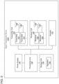
- FIG. 2 schematically illustrates an example monitoring device.
- FIG. 3 schematically illustrates an example signal transmission device.
- FIG. 4 illustrates another example signal transmission device.
- FIG. 5 schematically illustrates the example signal transmission device of FIG. 4 .
- FIG. 6 illustrates a plurality of lenses for the signal transmission device.
- FIG. 7 illustrates an adjustable lens for the signal transmission device.
- FIG. 8 illustrates a user interface for the monitoring device.
- FIG. 9 illustrates a method of acquiring a vital sign measurement using a radar signal transmission.
- FIG. 10 illustrates a method of adjusting a direction and focus of a radar signal transmission for acquiring a vital sign measurement.
- FIG. 11 illustrates an exemplary architecture of a computing device that can be used to implement aspects of the present disclosure.
- FIG. 1 schematically illustrates an example patient monitoring system 100 .
- the patient monitoring system 100 includes a monitoring device 102 configured to determine and display one or more vital signs of a subject S located in a subject arrangement area 104 .
- the vital signs are obtained noninvasively, without having to touch or contact the subject S.
- the vital signs may be displayed numerically, in waveform, in tabular data, in plots of tabular data, and the like.
- the subject S is a person, such as a patient, who is clinically treated by one or more medical professionals. As shown in FIG. 1 , the subject S is arranged in the subject arrangement area 104 , which can be located inside a healthcare facility such as a hospital, medical clinic, doctor's office, etc.
- the subject arrangement area 104 can include a support device 106 , such as a bed, on which the subject S can lie, rest, or sleep. Other examples of the support device 106 include lifts, chairs, stretchers, and surgical tables.
- the monitoring device 102 is operable to communicate with a data management system 108 via a data communication network 110 .
- the data management system 108 operates to manage personal and/or medical information, such as health conditions and other information of the subject S.
- the data management system 108 can be operated by medical professionals or healthcare service providers.
- the data management system 108 communicates with the monitoring device 102 .
- the monitoring device 102 and the data management system 108 are connected via the network 110 to transmit data such as measured vital signs and other data associated with the subject S.
- the monitoring device 102 is capable of directly communicating with the data management system 108 .
- the data management system 108 operates to provide information that can be used to assist trained medical professionals to provide suitable healthcare to the subject S. Examples of the data management system 108 include Connex® data management systems available from Welch Allyn Inc., Skaneateles Falls, N.Y.
- the data management system 108 may provide a connection to electronic medical record or electronic health record servers. Alternatively, the data management system 108 may itself be an electronic medical record server or an electronic health record server.
- the data communication network 110 communicates data between one or more computing devices, such as among the monitoring device 102 and the data management system 108 .
- Examples of the network 110 include a local area network and a wide area network, such as the Internet.
- the network 110 includes a wireless communication system, a wired communication system, or a combination of wireless and wired communication systems.
- a wired communication system can transmit data using electrical or optical signals in various possible configurations.
- Wireless communication systems typically transmit signals via electromagnetic waves, such as in the form of optical signals or radio frequency (RF) signals.
- RF radio frequency
- a wireless communication system can include an optical or RF transmitter for transmitting optical or RF signals, and an optical or RF receiver for receiving optical or RF signals.
- wireless communication systems include Wi-Fi communication devices that utilize wireless routers or wireless access points, cellular communication devices that utilize one or more cellular base stations, Bluetooth, ANT, ZigBee, medical body area networks, personal communications service (PCS), wireless medical telemetry service (WMTS), and other wireless communication devices and services.
- FIG. 2 illustrates an example of the monitoring device 102 .
- the monitoring device 102 includes a signal analysis device 120 , a signal transmission device 122 , and an aiming device 124 .
- the signal transmission device 122 and the aiming device 124 are attached to an external housing of the monitoring device 102
- the signal analysis device 120 is a hardware component of the monitoring device.
- the monitoring device 102 is a Connex® spot monitor available from Welch Allyn Inc., Skaneateles Falls, N.Y.
- the signal transmission device 122 operates to detect a vital sign of the subject S arranged in the subject arrangement area 104 .
- the signal transmission device 122 includes a radar signal transceiver to transmit radar signals toward the subject S and receive reflected radar signals, which can be used to determine the vital sign measurement.
- LIDAR, ultrasound, sonar, and the like may be used.
- the signal transmission device 122 includes an antenna. An example configuration of the signal transmission device 122 is described in more detail with reference to FIGS. 3 - 5 .
- the signal analysis device 120 operates to analyze the radar signals received from the signal transmission device 122 and determine a vital sign measurement.
- the signal analysis device 120 includes a processing device and at least one non-transitory computer readable data storage device storing instructions executable by the processing device.
- the signal analysis device 120 is integral with the signal transmission device 122 .
- Various methods used in the signal analysis device 120 and signal transmission device 122 are described herein.
- the aiming device 124 is configured to visually indicate the direction of the radar signals transmitted from the signal transmission device 122 .
- the aiming device 124 can be a laser or a light-emitting diode (LED) that emits a visible light in the direction of the radar signals transmitted from the signal transmission device 122 .
- the aiming device 124 assists a medical professional to direct the signal transmission device 122 towards an appropriate target area (e.g., the subject arrangement area 104 where the subject S is located), and even more specifically towards a specific anatomical area of the subject S such as the chest of the subject S.
- the visible light emitted from the aiming device 124 not only ensures that the signal transmission device 122 is pointed in an appropriate direction, but also provides a visual confirmation to a medical profession that data is being collected.
- FIG. 3 illustrates an example configuration of a signal transmission device 122 a .
- the signal transmission device 122 a includes a transmitter unit 126 , a receiver unit 128 , a processing unit 136 , a storage unit 138 , and a power supply 140 .
- these components are similar to the components described in U.S. patent application Ser. No. 15/679,570 filed on Aug. 17, 2017, the entirety of which is hereby incorporated by reference.
- the signal transmission device 122 a is configured as a radar module that uses radar signals to determine various characteristics of objects. For example, range and velocity are used to infer characteristics such as whether an object is accelerating or decelerating or if an object is rotating. Combinations of these motions are used to characterize the activity of the object.
- the signal transmission device 122 a is configured to detect one or more vital signs of the subject S, as described herein. In some examples, the signal transmission device 122 a is configured to incorporate at least some functionalities of the signal analysis device 120 .
- the transmitter unit 126 includes one or more signal transmitters 144 for producing radar signals, and one or more transmitting antennas 146 for transmitting the radar signals toward a target area such as the subject arrangement area 104 where the subject S is located (see for example FIG. 1 ). Other examples may use the same antenna(s) for transmission and reception.
- the radar signals transmitted from the transmitting antennas 146 reflect off objects (such as the subject S and surrounding objects in the subject arrangement area 104 ) and return to the receiver unit 128 .
- the signal transmitters 144 emit radar signals (also referred to as radio waves or electromagnetic waves) in predetermined directions through the transmitting antennas 146 .
- signal transmitters 144 use pulsed frequency chirping to emit radar signals at predetermined time intervals.
- signal transmitters 144 use frequency chirping to emit radar signals at predetermined time intervals of 50 milliseconds. When the radar signals come into contact with objects, the radar signals are reflected or scattered in many directions, with some radar signals reflected back towards the receiver unit 128 .
- the receiver unit 128 includes one or more signal receivers 148 and one or more receiving antennas 150 for receiving the radar signals reflected from objects such as the subject S.
- the same antennas can be used for both the receiving antennas 150 and the transmitting antennas 146 .
- the receiver unit 128 is arranged in the same location as, or adjacent to, the transmitter unit 126 .
- the reflected signals captured by the receiving antennas 150 can be strengthened by electronic amplifiers and/or signal-processed to recover useful radar signals.
- a plurality of signal transmitters 144 , a plurality of transmitting antennas 146 , a plurality of signal receivers 148 , and a plurality of receiving antennas 150 can be used to transmit signals to different directions or angles, and receive reflected signals from different directions or angles, thereby detecting different objects and/or different portions of a single object, which can be used to map different objects and/or different portions of an object within a target area that is being monitored by the signal transmission device 122 a .
- the antenna direction may be manually adjusted.
- the reflected radar signals received by the receiver unit 128 are delayed versions of the radar signals transmitted from the transmitter unit 126 .
- the radar signals that are reflected back towards the receiver unit 128 can be used to measure a vital sign of the subject S such as by monitoring changes in the frequency of the radar signals, caused by the Doppler effect, due to an object moving toward or away from the signal transmission device 122 a and to measure the range, caused by the delay in the received signal.
- the scale of the movement is small and the effect is termed micro-Doppler effect.
- Doppler effect and micro-Doppler effect are used interchangeably.
- the detected range and Doppler frequency of the radar signals caused by the chest of the subject S moving up and down during breathing can be measured to determine a respiration rate and a depth of respiration of the subject S.
- the phase of the reflected radar signals can be monitored to measure one or more vital signs of the subject S without having to contact the subject S.
- the signal transmission device 122 a uses millimeter waves (also referred to as mmWaves or millimeter band), which are in the spectrum between about 30 GHz and about 300 GHz. Millimeter waves are also known as extremely high frequency (EHF) waves. Millimeter waves have short wavelengths that can range from about 10 millimeters to about 1 millimeter.
- millimeter waves also referred to as mmWaves or millimeter band
- EHF extremely high frequency
- the processing unit 136 operates to control the transmitter unit 126 and the receiver unit 128 .
- the processing unit 136 is further configured to perform the functionalities of the signal analysis device 120 , such as processing and analyzing of the radar signals to determine a vital sign measurement of the subject S.
- the storage unit 138 includes one or more memories configured to store data associated with the radar signals and data usable to evaluate the radar signals.
- the storage unit 138 can be of various types, including volatile and nonvolatile, removable and non-removable, and/or persistent media.
- the storage unit 138 is an erasable programmable read only memory (EPROM) or flash memory.
- the power supply 140 provides power to operate the signal transmission device 122 a and associated elements.
- the power supply 140 includes one or more batteries, which is either for single use or rechargeable.
- the power supply 140 includes an external power source, such as mains power or external batteries.
- the signal transmission device 122 a is a phased array that electronically adjusts the direction and focus of the radar signal transmission.
- the storage unit 138 stores an algorithm 142 that uses the amplitude of the reflected radar signals to electronically adjust the direction and focus of the radar signal transmission.
- the algorithm 142 may be stored in a memory of the signal analysis device 120 .
- the algorithm 142 when executed by the processing unit 136 , causes the processing unit 136 to electronically steer the transmitting antennas 146 to adjust the direction of the radar signal transmission in the azimuth and elevation directions.
- the algorithm 142 causes the processing unit 136 to electronically focus the radar signal transmission by narrowing the dispersion of the radar signals (e.g., from 120 degrees to 40 degrees, 30 degrees, 20 degrees, etc.) to increase the density of the radar signals on a target area.
- the radar signals produced from the signal transmitters 144 are fed to the transmitting antennas 146 through phase shifters 154 , controlled by the processing unit 136 , which alter the phase of the radar signals electronically, to steer the radar signals to different directions.
- the algorithm 142 also adjusts the focus of the radar signals transmitted from the transmitting antennas 146 by controlling the dispersion of the radar signals in a particular direction. Electronically controlling the direction and focus of the radar signals emitted from the transmitting antennas 146 reduces noise and improves the signal strength.
- the phase shifter 154 may also be incorporated in the receiver unit 128 .
- one example target area for the radar signal transmission is the torso of the subject S.
- the algorithm 142 when executed by the processing unit 136 not only causes the signal transmission device 122 a to direct the transmission of the radar signals on the torso, but also causes the signal transmission device 122 a to focus the transmission of the radar signals on a particular area on the torso.
- the algorithm 142 can direct the signal transmission device 122 a to focus the radar signal transmission on the chest of the subject S.
- a change in the frequency of the reflected radar signals that result from the chest of the subject S moving up and down during breathing can be monitored by the signal transmission device 122 a to determine a respiration rate of the subject S.
- a depth of respiration of the subject S can also be measured by the signal transmission device 122 a by monitoring the delay of the reflected radar signals. Inhalation and exhalation may also be detected by determining whether the delay is increasing or decreasing. Because of the small motion relative to a wavelength, the delay may be detected as a phase shift.
- the signal analysis device 120 uses the algorithm 142 to steer the transmission of the radar signals elsewhere, for example, towards the abdomen (e.g., stomach) of the subject S.
- the subject S is a belly breather, which is also known as abdominal breathing or diaphragmatic breathing, and which causes the stomach of the subject S to expand as the subject S inhales
- the signal analysis device 120 uses the algorithm 142 to steer the signal transmission device 122 a in a direction to focus the transmission of the radar signals on a different area of the torso such as the abdomen of the subject S for measuring respiration rate.
- the signal analysis device 120 uses the algorithm 142 to steer the signal transmission device 122 a to focus the transmission of the radar signals on two target areas simultaneously, such as the chest and abdomen of the subject S, and the signal transmission device 122 a uses time multiplexing between the two target areas to measure the respiration rate of the subject S more accurately.
- the algorithm 142 can be used by the signal transmission device 122 a to focus the transmission of the radar signals on other target areas of the torso of the subject S, such as an area between the ribs at which the apex of the heart pushes. By focusing the transmission of radar signals on this area of the ribs and by using the Doppler effect as described above, the heart rate of the subject S can be determined. Alternatively, ranging methods, including those associated with chirped radar pulses, may be used to determine the heart rate of the subject S.
- the signal transmission device 122 a when performing the algorithm 142 , scans a wide field of view such as a room where the subject S is located.
- the field of view scanned by the signal transmission device 122 a can be 120 degrees or greater.
- the algorithm 142 automatically focuses the radar signal transmission from the signal transmission device 122 a by narrowing the field of view on the target area where the signal is detected. This can improve the signal quality and reduce noise. Thereafter, the signal transmission device 122 a can monitor the detected signal to determine a vital sign measurement.
- the algorithm 142 can be used to distinguish between different subjects in the wide field of view (e.g., 120 degrees) of the signal transmission device 122 a .
- a patient such as the subject S is in a bed with relatively little motion, and a nurse is present in the patient's room and is ambulate (e.g., moving from place to place within the room).
- a band-pass Doppler filter is used to select the output of the radar to ignore objects that move above a certain velocity and to ignore objects that are motionless.
- a clutter filter may also be used to subtract background objects.
- the radar can scan and track multiple people in the patient's room and ignore those who ambulate, such as the nurse.
- Filters may also be designed that selectively allow known respiration models, which include depth, rate, overall rhythm, inhalation to exhalation time, slope of the inhalation curve, slope of the exhalation curve, and time in a relaxed state between exhalation and inhalation.
- respiration models which include depth, rate, overall rhythm, inhalation to exhalation time, slope of the inhalation curve, slope of the exhalation curve, and time in a relaxed state between exhalation and inhalation.
- Matched filters may also be used to detect valid respiration signals, and this detection is used as positive feedback and the optimal direction of the phased-grid array antenna may be obtained by maximizing this signal over the range of azimuth and elevation angles.
- Other methods of detecting valid respiration such as machine learning and pattern recognition may also be used.
- an area can be scanned for identifying a specific patient within the area by placing a tag on the patient to act as a “beacon” so that the signal transmission device 122 a can identify the correct patient and set of vitals within the area.
- the tag can emit IR light, video, NFC, RF, or low frequency sound as a beacon or source signal that is detected by the signal transmission device 122 a.
- FIGS. 4 and 5 illustrate another example configuration of a signal transmission device 122 b that uses automatic target recognition (ATR) to mechanically steer the signal transmission device 122 b .
- the signal transmission device 122 b is similar to the signal transmission device 122 a described above and utilizes similar workflows such as to distinguish between different subjects in the wide field of view of the signal transmission device 122 b .
- the signal transmission device 122 b includes a transmitter unit 126 , a receiver unit 128 , a processing unit 136 , a storage unit 138 , and a power supply 140 , and is configured as a radar module that uses radar signals to determine various characteristics of objects such as one or more vital signs of the subject S, as described herein.
- the signal transmission device 122 b is attached to an exterior housing 112 of the monitoring device 102 by a pivoted support 130 .
- the pivoted support 130 is a gimbal or gyroscope. The pivoted support 130 allows the signal transmission device 122 b to be rotated about an azimuth axis A-A and an elevation axis E-E.
- the storage unit 138 stores the algorithm 142 that is used by the signal transmission device 122 b to recognize and track the movement of a target area based on data obtained from the reflected radar signals.
- the algorithm 142 may be stored in a memory of the signal analysis device 120 .
- the algorithm used by the signal transmission device 122 b is different from the algorithm used by the signal transmission device 122 a .
- the algorithm used by the signal transmission device 122 b is the same as the algorithm used by the signal transmission device 122 a.
- the transmitter unit 126 includes one or more signal transmitters 144 for producing radar signals, and one or more transmitting antennas 146 for transmitting the radar signals toward a target area.
- Data from the reflected radar signals is received by the receiver unit 128 that includes one or more signal receivers 148 and one or more receiving antennas 150 for receiving the radar signals reflected from objects such as the subject S.
- the data from the reflected radar signals is used by the algorithm 142 to detect a signal and identify a target area (e.g., the chest of the subject S).
- the algorithm 142 when executed by the processing unit 136 , causes the processing unit 136 to drive an actuator 132 to mechanically steer the pivoted support 130 .
- the signal transmission device 122 b can be mechanically steered about the azimuth axis A-A and the elevation axis E-E (see FIG. 4 ) so that the signal transmission device 122 b is pointed in the direction of the target area to reduce noise and improve signal strength.
- the data from the reflected radar signals is monitored and the processing unit 136 uses the algorithm 142 to track a movement of the target area such that when the subject S moves in or out of the support device 106 , the signal transmission device 122 b is mechanically steered so that it remains pointed in the direction of the target area to reduce noise and maintain signal strength even when the subject S moves.
- the signal transmission device 122 b uses feature vectors to identify the target area.
- a feature vector is a property or characteristic that can be measured.
- a feature vector is a one-dimensional matrix used to describe a measured property or characteristic such as the thoracic motion that describes inhalation, rest, exhalation, and rest. More detailed feature vectors allow detection of different depths and rates of respiration, and for detection of respiratory features that indicate ailments such as rales (which are abnormal lung sounds characterized by discontinuous clicking or rattling sounds) and stridor (which is a high-pitched, wheezing sound caused by disrupted airflow).
- rales which are abnormal lung sounds characterized by discontinuous clicking or rattling sounds
- stridor which is a high-pitched, wheezing sound caused by disrupted airflow.
- the automatic target recognition of the signal transmission device 122 b may include both time-domain (e.g. matched filters) and frequency domain (fast Fourier transform, fast Hartley transform, short fast Fourier transform) analysis. Additionally, mixed domain analysis processing and filters (e.g. wavelets, Gabor transform, Wigner Distribution Function) may be used.
- time-domain e.g. matched filters
- frequency domain fast Fourier transform, fast Hartley transform, short fast Fourier transform
- mixed domain analysis processing and filters e.g. wavelets, Gabor transform, Wigner Distribution Function
- a weighting algorithm may be used to weight the importance of each detected feature as part of a classification algorithm.
- FIG. 6 illustrates a plurality of lenses 114 a - 114 e .
- Each lens 114 a - 114 e is configured to attach to the signal transmission device 122 and to focus the radar signals transmitted from the signal transmission device 122 on a target area.
- Each lens 114 a - 114 e is attachable to the signal transmission device 122 by screwing onto or snap-fitting onto an exterior housing of the signal transmission device 122 or by using one or more clamps, screws, bolts, etc.
- the beam of radar signals transmitted from the signal transmission device 122 is a combination of the antenna effects and the lens effects. Both may be adjusted to optimize the radar signal transmission.
- Each lens 114 a - 114 e narrows the dispersion of the radar signals transmitted from the signal transmission device 122 so that a higher density of radar signals are directed to the target area for measuring vital signs such as respiration rate, depth of respiration, or heart rate.
- vital signs such as respiration rate, depth of respiration, or heart rate.
- the radar signals transmitted from the signal transmission device 122 are dispersed at 120 degrees, and each lens can narrow the dispersion of the radar signals from 120 degree to 40 degrees, 30 degrees, 20 degrees, etc.
- the lenses 114 a - 114 e are configured to collimate the radar signals transmitted from the signal transmission device 122 so that the radar signals are focused on the target area. By focusing the dispersion of the radar signals, the lenses 114 a - 114 e reduce noise and improve signal strength.
- the lenses 114 a - 114 e are replaceable with another so that each lens 114 a - 114 e can provide a different focus (e.g., 40 degrees, 30 degrees, 20 degrees, etc.) for the radar signals transmitted from the signal transmission device 122 .
- a particular lens 114 a - 114 e can be selected as may be needed or desired for a particular application to provide a desired focus for the radar signals from the signal transmission device 122 .
- FIG. 7 illustrates an adjustable lens 114 e for the signal transmission device 122 .
- the adjustable lens 114 e can adjust the focus of the radar signals as needed.
- the adjustable lens 114 e can adjust the focus of the radar signals from a large dispersion (e.g., 120 degrees) to a smaller, more focused dispersion (e.g., 40 degrees, 30 degrees, 20 degrees, etc.).
- the adjustable lens 114 e automatically moves to locate the strongest signal in the target area.
- the adjustable lens 114 e can include a handle 116 that is slidable through a groove 118 for adjusting the focus of the radar signals.
- the lenses 114 a - 114 e are illustrated as molded from an opaque plastic material. In other examples, the lenses 114 a - 114 e are molded from a clear plastic material. In examples where a clear plastic material is used, the aiming device 124 can be located behind the lens to emit a visible light through the lens for visually indicating the target area in the direction of the transmission of the radar signals. In certain examples, lenses 114 a - 114 e are used without or separately from the aiming device 124 .
- FIG. 8 illustrates a user interface 180 for the monitoring device 102 .
- the user interface 180 includes a display 182 for the breathing rate (i.e., respiration rate) and a display 184 for the heart rate determined by the monitoring device 102 .
- the user interface 180 further includes a display 190 for the chest displacement (i.e., depth of respiration) determined by the monitoring device 102 .
- the user interface 180 may provide other information including a quality indication, a range indication, an uncertainty indication, a signal-to-noise indication, and a patient movement indication.
- the patient movement indication may be adapted to a Braden mobility scale related to probability of bedsores occurring.
- the user interface 180 also displays an amplitude module 186 that indicates the time-varying signal from which features such as the breathing rate (i.e., respiration rate) and depth of respiration are extracted, and an amplitude module 188 that indicates the time-varying heart signal from which features such as the heart rate are extracted.
- the amplitude modules 186 , 188 display the breathing rate and heart rate amplitudes, respectively, as waveforms on the user interface 180 .
- the amplitude modules 186 , 188 display the breathing rate and heart rate amplitudes, respectively, as numerical values.
- the breathing rate and heart rate amplitudes displayed on the user interface 180 provide further indication that the monitoring device 102 is active and sensing one or more vital signs.
- the user interface 180 further includes an indicator module 192 to provide user guidance for a need to move the signal transmission device 122 to improve signal strength.
- the indicator module 192 can provide user guidance on movement in the azimuth and elevation directions for the signal transmission device 122 to improve the signal strength.
- the user interface 180 includes a range profile indicator 194 that indicates a range of the reflected radar signals received by the signal transmission device 122 .
- the range profile indicator 194 ensures that the breathing rate and heart rate are determined based on data from reflected radar signals that are within a predetermined range of the monitoring device 102 , and accordingly ensures the veracity of the vital sign measurements.
- Data such as respiration rate can be stored on the monitoring device 102 . Further, the data can be communicated by the monitoring device 102 to a remote computing device such as the data management system 108 for storage in an electronic medical record of the patient.
- a remote computing device such as the data management system 108 for storage in an electronic medical record of the patient.
- FIG. 9 illustrates a method 300 of acquiring a vital sign measurement.
- the method 300 is implemented by the signal analysis device 120 .
- the method 300 is implemented by the signal transmission device 122 .
- the method 300 includes a step 302 of transmitting radar signals.
- the monitoring device 102 includes a transmitter unit 126 having one or more signal transmitters 144 for producing radar signals and one or more transmitting antennas 146 for transmitting the radar signals toward a target area such as the subject arrangement area 104 where a subject S is located (see, for example, FIG. 1 ).
- the method 300 includes a step 304 of receiving reflected radar signals.
- the monitoring device 102 further includes a receiver unit 128 having one or more signal receivers 148 and one or more receiving antennas 150 for receiving the radar signals reflected from objects such as the subject S in the subject arrangement area 104 .
- the method 300 includes a step 306 of determining a vital sign measurement based on data from the reflected radar signals.
- An algorithm is stored in the storage device of the signal analysis device 120 and is used to determine the vital sign measurement based on the raw data collected from the reflected radar signals.
- the algorithm is stored in the storage unit 138 of the signal transmission device 122 .
- the raw data may also be transmitted to an external computer for analysis and/or addition to a database of signals.
- the raw data may also be clinically annotated with diagnoses and outcomes.
- the data used by the algorithm to determine the vital sign measurement includes changes in the frequency of the reflected radar signals, caused by the Doppler effect, due to an object moving toward or away from the signal transmission device 122 .
- changes in the frequency of the reflected radar signals caused by the chest of the subject S moving up and down during breathing can be used by the algorithm to determine respiration rate, depth of respiration, or heart rate.
- the monitoring device 102 determines one or more vital sign measurements of the subject S without having to contact the subject S.
- the method 300 uses at least one of detection theory, pattern classification, neural networks, artificial intelligence, cloud-based computing, and image processing to determine a vital sign measurement.
- the algorithm used by the method 300 may receive inputs for patient ethnographics including gender, age, weight, race, and medical history.
- the method 300 uses at least one of Fourier transform, fast Fourier transform (FFT), short Fourier transform (SFT), fast Hartley transform, wavelet analysis, Gabor transform, or Wigner distribution function (WVD) to determine a vital sign measurement.
- the Fourier transform may be used to determine the frequency content of a signal. If the frequency content is within an expected range (e.g., 4 to 30 beats for respiration rate), then the signal is accepted.
- Fast Fourier transforms are a computationally efficient method of applying Fourier transforms and fast Hartley transforms are efficient methods of determining the frequency content of a signal.
- Wavelet, Gabor, and Wigner methods are appropriate when both temporal and frequency content are needed (as typical Fourier and Hartley transforms with high frequency content have low temporal resolution).
- Conversion of the raw data to the frequency domain allows characterization of the raw data, for example, relative and phase amplitudes of harmonics.
- Stridor, rales, and other pulmonary issues have characteristic sounds and hence characteristic frequencies that modulate the signal.
- the ratio of amplitudes of different harmonics provides guidance on the quality of the respiration effort (e.g., how clean or unhampered the respiration effort is). For example, two patients can have the same respiration rate (e.g., at 12 breaths/min), but one patient's respiration can be labored and the waveform will appear jagged which indicates difficult breathing.
- the quality of the patient's respiration can be assessed along with the amplitude of the breath as the chest inflects and deflects.
- the method 300 may include further steps to subtract background noise, and thereby improve the quality of the vital sign measurement.
- the method 300 uses range filters to remove reflected radar signals that are outside a predetermined range of distance when determining the vital sign measurement.
- range filters can ensure that only reflected radar signals that travel between the monitoring device 102 and the subject arrangement area 104 are analyzed to determine the vital sign measurement.
- the method 300 uses time and frequency-domain filters to remove reflected radar signals outside a predetermined frequency range when determining the vital sign measurement.
- the received waveform may be correlated with the expected shape of a known respiration waveform to discriminate against non-respiratory signals before determining the respiratory rate.
- Clutter filters may be used to subtract out ambient background reflections.
- Low-pass Doppler filters can be used to remove signals from ambulating persons (e.g., nurses) while preserving the signals from patients lying in bed.
- the filter shapes and frequencies preferably vary with patient demographics and can be adapted to the patient.
- the acceptable range for respiration rate is much higher for neonatal patients than for adults and the width of the breaths is smaller, so the frequency content of the physiological modulation of the radar signal is higher than would be expected for an adult.
- the time- and frequency-domain filters adapt to match the characteristics of that patient, which allows the system to further ignore noise. For example, a patient with a fast inhalation cycle has more energy in higher-frequency components than a patient with the same respiration rate and a slower inhalation cycle.
- the method 300 uses a Doppler filter to accept only reflected radar signals within a predetermined frequency range when determining the vital sign measurement. For example, objects having no motion such as a bed or chair, and hence no Doppler signal, are removed when performing the method 300 so that only a moving object is analyzed.
- a high-pass output of a Doppler filter can be used to reject the motionless objects.
- a clutter filter is used to subtract a previous output from a high-pass Doppler filter from a new radar return. Objects identified as moving beyond a predetermined threshold are rejected or ignored such as, for example, a nurse walking into the room.
- the Doppler filter has a low-pass component that ignores high-frequency signals from ambulating persons (e.g., the nurse). The net is a band pass filter that ignores high-motion and no-motion objects.
- the method 300 uses a micro-Doppler effect to identify a target area (e.g., the subject S lying in the support device 106 ) and guide the radar signal transmission.
- respiration can create an expected phase change of about x*2 ⁇ / ⁇ , where x is the chest displacement and ⁇ is the wavelength of the transmitted signal, and this signal is on the order of about 0.5 mm at a frequency of about 60 GHz.
- a targeting algorithm can scan for a target area with a periodic micro-Doppler variation of amplitude approximately 0.5 mm.
- the method 300 uses azimuth and elevation filters to remove reflected radar signals outside a predetermined direction when determining the vital sign measurement. For example, reflected radar signals that are outside of an azimuth or elevation range where the subject S is located are removed by the azimuth and elevation filters.
- the method 300 uses frequency chirping to transmit the radar signals. In some examples, the method 300 transmits the radar signals using frequency chirping at predetermined time intervals of 50 milliseconds. In further examples, the method 300 uses millimeter waves in a spectrum between about 30 GHz and about 300 GHz.
- FIG. 10 illustrates a method 400 of adjusting a direction and focus of a radar signal transmission for acquiring a vital sign measurement.
- the method 400 may further improve the quality of the vital sign measurement.
- the method 400 is implemented by the signal transmission device 122 . In an alternative example embodiment, the method 400 is implemented by the signal analysis device 120 .
- the method 400 includes a step 402 of transmitting radar signals in a direction toward a target area such as the chest of the subject S.
- the aiming device 124 can be used to provide a course aim for directing the radar signal transmission from the monitoring device 102 by optically illuminating the center of the radar signal transmission so that a medical professional can view where the radar signal transmission is pointed.
- the visual marker from the aiming device 124 provides an indicator to the medical professional that the monitoring device 102 is active and sensing a vital sign such as respiration rate.
- the method 400 includes a step 404 of receiving reflected signals.
- the amplitude of the reflected signals is displayed on the user interface 180 of the monitoring device 102 as a further indicator that the monitoring device 102 is active and sensing one or more vital signs such as respiration rate.
- the reflected signals are used to determine a target nominal range.
- the amplitude of the vital signs signal is displayed as a waveform on the user interface 180 .
- the amplitude of the vital signs signal is displayed as a numerical value on the user interface 180 .
- the method 400 includes a step 406 of adjusting the direction of the radar signal transmission.
- the direction of the radar signal transmission can be adjusted by using an amplitude of reflected radar signals, and can be adjusted in both the azimuth and elevation directions.
- the direction of the transmission of radar signals is adjusted electronically by the phased array of the signal transmission device 122 a .
- the direction of the radar signal transmission is adjusted by mechanically steering the pivoted support 130 of the signal transmission device 122 b.
- the method 400 includes a step 408 of adjusting a focus of the radar signal transmission.
- the focus of the radar signal transmission is adjusted electronically by the phased array of the signal transmission device 122 a .
- the focus of the radar signal transmission is adjusted by placing a lens 114 a - 114 e over the signal transmission device 122 b .
- the lens is an adjustable lens 114 e that automatically adjusts the focus of the radar signal transmission or that can be manually manipulated to further adjust the focus of the radar signal transmission.
- the method 400 includes a step 410 of determining a vital sign measurement based on data from the reflected radar signals.
- An algorithm stored in the storage device of the signal analysis device 120 or in the storage unit 138 of the signal transmission device 122 is used to determine the vital sign measurement based on data collected from the reflected radar signals.
- the data used by the algorithm to calculate the vital sign measurement includes changes in the frequency of the reflected radar signals, caused by the Doppler effect, due to an object moving toward or away from the signal transmission device 122 . For example, changes in the frequency of the reflected radar signals caused by the chest of the subject S moving up and down during breathing can be used by the algorithm to determine respiration rate, depth of respiration, or heart rate.
- the monitoring device 102 determines one or more vital sign measurements of the subject S without having to contact the subject S.
- FIG. 11 illustrates an exemplary architecture of a computing device 200 which can be used to implement aspects of the present disclosure, including the monitoring device 102 and the data management system 108 , and will be referred to herein as the computing device 200 .
- the computing device 200 is used to execute the operating system, application programs, and software modules (including the software engines) described herein.
- the monitoring device 102 and the data management system 108 can include all or some of the elements described with reference to FIG. 11 , with or without additional elements.
- the computing device 200 includes, in some examples, at least one processing device 202 , such as a central processing unit (CPU).
- processing devices are available from a variety of manufacturers, for example, Intel or Advanced Micro Devices.
- the computing device 200 also includes a system memory 204 , and a system bus 206 that couples various system components including the system memory 204 to the processing device 202 .
- the system bus 206 is one of any number of types of bus structures including a memory bus, or memory controller; a peripheral bus; and a local bus using any of a variety of bus architectures.
- the system memory 204 may include read only memory 208 and random access memory 210 .
- the computing device 200 also includes a secondary storage device 214 in some embodiments, such as a hard disk drive, for storing digital data.
- the secondary storage device 214 is connected to the system bus 206 by a secondary storage interface 216 .
- the secondary storage devices and their associated computer readable media provide nonvolatile storage of computer readable instructions (including application programs and program modules), data structures, and other data for the computing device 200 .
- exemplary environment described herein employs a hard disk drive as a secondary storage device
- other types of computer readable storage media are used in other embodiments. Examples of these other types of computer readable storage media include magnetic cassettes, flash memory cards, digital video disks, Bernoulli cartridges, compact disc read only memories, digital versatile disk read only memories, random access memories, or read only memories. Some embodiments include non-transitory media.
- a number of program modules can be stored in secondary storage device 214 or memory 204 , including an operating system 218 , one or more application programs 220 , other program modules 222 , and program data 224 .
- the computing device 200 includes input devices to enable a user to provide inputs to the computing device 200 .
- input devices 226 include a keyboard 228 , a pointer input device 230 , a microphone 232 , and a touch sensitive display 240 .
- Other embodiments include other input devices.
- the input devices are often connected to the processing device 202 through an input/output interface 238 that is coupled to the system bus 206 .
- These input devices 226 can be connected by any number of input/output interfaces, such as a parallel port, serial port, game port, or a universal serial bus.
- Wireless communication between input devices and the input/output interface 238 is possible as well, and includes infrared, BLUETOOTH® wireless technology, 802.11a/b/g/n, cellular, or other radio frequency communication systems in some possible embodiments.
- a touch sensitive display 240 is connected to the system bus 206 via an interface, such as a video adapter 242 .
- the touch sensitive display 240 includes touch sensors for receiving input from a user when the user touches the display.
- Such sensors can be capacitive sensors, pressure sensors, or other touch sensors.
- the sensors detect contact with the display, and also the location and movement of the contact over time. For example, a user can move a finger or stylus across the screen to provide written inputs. The written inputs are evaluated and, in some embodiments, converted into text inputs.
- the computing device 200 can include various other peripheral devices (not shown), such as speakers or a printer.
- the computing device 200 further includes a communication device 246 configured to establish communication across a network.
- a communication device 246 configured to establish communication across a network.
- the computing device 200 when used in a local area networking environment or a wide area networking environment (such as the Internet), the computing device 200 is typically connected to the network through a network interface, such as a wireless network interface 250 .
- a network interface such as a wireless network interface 250 .
- Other possible embodiments use other wired and/or wireless communication devices.
- some embodiments of the computing device 200 include an Ethernet network interface, or a modem for communicating across the network.
- the communication device 246 is capable of short-range wireless communication.
- Short-range wireless communication is one-way or two-way short-range to medium-range wireless communication.
- Short-range wireless communication can be established according to various technologies and protocols. Examples of short-range wireless communication include a radio frequency identification (RFID), a near field communication (NFC), a Bluetooth technology, and a Wi-Fi technology.
- RFID radio frequency identification
- NFC near field communication
- Bluetooth Bluetooth technology
- Wi-Fi Wi-Fi
- the computing device 200 typically includes at least some form of computer-readable media.
- Computer readable media includes any available media that can be accessed by the computing device 200 .
- Computer-readable media include computer readable storage media and computer readable communication media.
- Computer readable storage media includes volatile and nonvolatile, removable and non-removable media implemented in any device configured to store information such as computer readable instructions, data structures, program modules or other data.
- Computer readable storage media includes, but is not limited to, random access memory, read only memory, electrically erasable programmable read only memory, flash memory or other memory technology, compact disc read only memory, digital versatile disks or other optical storage, magnetic cassettes, magnetic tape, magnetic disk storage or other magnetic storage devices, or any other medium that can be used to store the desired information and that can be accessed by the computing device 200 .
- Computer readable storage media does not include computer readable communication media.
- Computer readable communication media typically embodies computer readable instructions, data structures, program modules or other data in a modulated data signal such as a carrier wave or other transport mechanism and includes any information delivery media.
- modulated data signal refers to a signal that has one or more of its characteristics set or changed in such a manner as to encode information in the signal.
- computer readable communication media includes wired media such as a wired network or direct-wired connection, and wireless media such as acoustic, radio frequency, infrared, and other wireless media. Combinations of any of the above are also included within the scope of computer readable media.
- the computing device 200 is an example of programmable electronics, which may include one or more computing devices, and when multiple computing devices are included, such computing devices can be coupled together with a suitable data communication network so as to collectively perform the various functions, methods, or operations disclosed herein.
- the computing device 200 can include a location identification device 248 .
- the location identification device 248 is configured to identify the location or geolocation of the computing device 200 .
- the location identification device 248 can use various types of geolocating or positioning systems, such as network-based systems, handset-based systems, SIM-based systems, Wi-Fi positioning systems, and hybrid positioning systems.
- Network-based systems utilize service provider's network infrastructure, such as cell tower triangulation.
- Handset-based systems typically use the Global Positioning System (GPS).
- GPS Global Positioning System
- Wi-Fi positioning systems can be used when GPS is inadequate due to various causes including multipath and signal blockage indoors.
- Hybrid positioning systems use a combination of network-based and handset-based technologies for location determination, such as Assisted GPS.
- Embodiments of the present invention may be utilized in various distributed computing environments where tasks are performed by remote processing devices that are linked through a communications network in a distributed computing environment.
- the monitoring device 102 more efficiently captures vital sign measurements including respiration rate, depth of respiration, and heart rate. Additionally, the monitoring device 102 determines vital sign measurements more accurately and in less time. Finally, the captured vitals can be more efficiently displayed.
Landscapes
- Health & Medical Sciences (AREA)
- Life Sciences & Earth Sciences (AREA)
- Engineering & Computer Science (AREA)
- Physics & Mathematics (AREA)
- Remote Sensing (AREA)
- Radar, Positioning & Navigation (AREA)
- Public Health (AREA)
- Veterinary Medicine (AREA)
- Biophysics (AREA)
- Biomedical Technology (AREA)
- Heart & Thoracic Surgery (AREA)
- Medical Informatics (AREA)
- Molecular Biology (AREA)
- Surgery (AREA)
- Animal Behavior & Ethology (AREA)
- General Health & Medical Sciences (AREA)
- Pathology (AREA)
- Physiology (AREA)
- Computer Networks & Wireless Communication (AREA)
- Cardiology (AREA)
- General Physics & Mathematics (AREA)
- Pulmonology (AREA)
- Electromagnetism (AREA)
- Psychiatry (AREA)
- Artificial Intelligence (AREA)
- Computer Vision & Pattern Recognition (AREA)
- Signal Processing (AREA)
- Nuclear Medicine, Radiotherapy & Molecular Imaging (AREA)
- Radiology & Medical Imaging (AREA)
- Oral & Maxillofacial Surgery (AREA)
- Dentistry (AREA)
- Measurement Of The Respiration, Hearing Ability, Form, And Blood Characteristics Of Living Organisms (AREA)
- Measuring And Recording Apparatus For Diagnosis (AREA)
Abstract
Description
Claims (17)
Priority Applications (1)
| Application Number | Priority Date | Filing Date | Title |
|---|---|---|---|
| US16/748,293 US11653848B2 (en) | 2019-01-29 | 2020-01-21 | Vital sign detection and measurement |
Applications Claiming Priority (2)
| Application Number | Priority Date | Filing Date | Title |
|---|---|---|---|
| US201962798124P | 2019-01-29 | 2019-01-29 | |
| US16/748,293 US11653848B2 (en) | 2019-01-29 | 2020-01-21 | Vital sign detection and measurement |
Publications (2)
| Publication Number | Publication Date |
|---|---|
| US20200237252A1 US20200237252A1 (en) | 2020-07-30 |
| US11653848B2 true US11653848B2 (en) | 2023-05-23 |
Family
ID=69375270
Family Applications (1)
| Application Number | Title | Priority Date | Filing Date |
|---|---|---|---|
| US16/748,293 Active 2041-02-12 US11653848B2 (en) | 2019-01-29 | 2020-01-21 | Vital sign detection and measurement |
Country Status (3)
| Country | Link |
|---|---|
| US (1) | US11653848B2 (en) |
| EP (1) | EP3689233A1 (en) |
| CN (1) | CN111481202A (en) |
Cited By (1)
| Publication number | Priority date | Publication date | Assignee | Title |
|---|---|---|---|---|
| US20210169361A1 (en) * | 2019-12-10 | 2021-06-10 | Hill-Rom Services, Inc. | Micro-movement and gesture detection using radar |
Families Citing this family (10)
| Publication number | Priority date | Publication date | Assignee | Title |
|---|---|---|---|---|
| US11877844B2 (en) * | 2020-02-19 | 2024-01-23 | Hill-Rom Services, Inc. | Respiration detection using radar |
| US11322252B2 (en) * | 2020-04-28 | 2022-05-03 | Phoenix Children's Hospital, Inc. | System and methods for asset tracking |
| CN112336307B (en) * | 2020-10-30 | 2023-05-23 | 甘肃省人民医院 | Real-time dynamic prevention and detection system for pressure damage based on optical sensor |
| GB2600975A (en) * | 2020-11-13 | 2022-05-18 | Elotec As | Optimization of dataset |
| CN112716462B (en) * | 2020-12-09 | 2022-04-05 | 北京航空航天大学 | Narrow-beam millimeter wave human body heartbeat/respiration sign monitoring device capable of controlling irradiation direction |
| CN112731365A (en) * | 2020-12-25 | 2021-04-30 | 武汉飞恩微电子有限公司 | Vehicle environment detection system and method |
| CN112890772A (en) * | 2021-01-14 | 2021-06-04 | 四川写正智能科技有限公司 | Health index monitoring method and system for child smart watch |
| CN115113195A (en) | 2021-03-17 | 2022-09-27 | 纬创资通股份有限公司 | Frequency modulation continuous wave radar system and identity and information detection method thereof |
| US11813043B2 (en) * | 2021-12-03 | 2023-11-14 | Structured Monitoring Products, Inc. | System and methods for detection of subjects vitals and physiological symptoms via non-contact methods |
| CN115590489B (en) * | 2022-09-28 | 2024-01-23 | 中国人民解放军总医院 | Contactless blood pressure monitoring method based on frequency modulation continuous wave radar |
Citations (33)
| Publication number | Priority date | Publication date | Assignee | Title |
|---|---|---|---|---|
| US2603749A (en) * | 1946-04-08 | 1952-07-15 | Bell Telephone Labor Inc | Directive antenna system |
| US2887684A (en) * | 1954-02-01 | 1959-05-19 | Hughes Aircraft Co | Dielectric lens for conical scanning |
| US7119758B2 (en) * | 2003-10-31 | 2006-10-10 | Thomson Licensing | High frequency, multiple beam antenna system |
| US20070060802A1 (en) | 2003-05-08 | 2007-03-15 | Nejhdeh Ghevondian | Patient monitor |
| WO2008001092A2 (en) | 2006-06-28 | 2008-01-03 | Cambridge Consultants Limited | Radar for through wall detection |
| US20100249630A1 (en) * | 2008-04-03 | 2010-09-30 | Kai Medical, Inc. | Systems and methods for respiratory rate measurement |
| US20110263952A1 (en) | 2004-11-03 | 2011-10-27 | Fred Bergman Healthcare Pty Ltd | Incontinence management system and diaper |
| US8068053B1 (en) * | 2006-06-13 | 2011-11-29 | Ball Aerospace & Technologies Corp. | Low-profile lens method and apparatus for mechanical steering of aperture antennas |
| EP2438849A1 (en) | 2010-10-06 | 2012-04-11 | Latvijas Universitate | Device and method for an optical contactless monitoring of cardiac parameters |
| US20130019405A1 (en) | 2011-07-19 | 2013-01-24 | Joseph Flanagan | Moisture detection system |
| US20130345568A1 (en) | 2012-06-25 | 2013-12-26 | Xerox Corporation | Video-based estimation of heart rate variability |
| WO2014030091A1 (en) | 2012-08-24 | 2014-02-27 | Koninklijke Philips N.V. | Method and apparatus for measuring physiological parameters of an object |
| WO2014055755A1 (en) | 2012-10-05 | 2014-04-10 | TransRobotics, Inc. | Systems and methods for high resolution distance sensing and applications |
| US8761853B2 (en) | 2011-01-20 | 2014-06-24 | Nitto Denko Corporation | Devices and methods for non-invasive optical physiological measurements |
| US20140275833A1 (en) | 2013-03-15 | 2014-09-18 | Hill-Rom Services, Inc. | Measuring multiple physiological parameters through blind signal processing of video parameters |
| US20140276504A1 (en) | 2013-03-13 | 2014-09-18 | Hill-Rom Services, Inc. | Methods and apparatuses for the detection of incontinence or other moisture, methods of fluid analysis, and multifunctional sensor systems |
| US20140303454A1 (en) | 2011-08-22 | 2014-10-09 | Isis Innovation Limited | Remote monitoring of vital signs |
| US9020185B2 (en) | 2011-09-28 | 2015-04-28 | Xerox Corporation | Systems and methods for non-contact heart rate sensing |
| WO2015078735A1 (en) | 2013-11-27 | 2015-06-04 | Koninklijke Philips N.V. | Device and method for obtaining pulse transit time and/or pulse wave velocity information of a subject |
| WO2015086338A1 (en) | 2013-12-12 | 2015-06-18 | Koninklijke Philips N.V. | Device and method for determining vital signs of a subject |
| US20150201859A1 (en) | 2013-12-04 | 2015-07-23 | Welch Allyn, Inc. | Analysis of Direct and Indirect Heartbeat Data Variations |
| US20150282724A1 (en) | 2014-04-02 | 2015-10-08 | Massachusetts Institute Of Technology | Methods and Apparatus for Physiological Measurement Using Color Band Photoplethysmographic Sensor |
| US20150302158A1 (en) | 2014-04-21 | 2015-10-22 | Microsoft Corporation | Video-based pulse measurement |
| US20150379370A1 (en) | 2013-02-12 | 2015-12-31 | Isis Innovation Limited | Method and system for signal analysis |
| US20160081618A1 (en) * | 2013-05-31 | 2016-03-24 | The Johns Hopkins University | Systems and methods for ultra-wideband (uwb) radar detection and tracking of tumors in real-time |
| WO2016092290A1 (en) | 2014-12-08 | 2016-06-16 | Oxehealth Limited | Method and apparatus for physiological monitoring |
| WO2016123287A1 (en) | 2015-01-28 | 2016-08-04 | Google Inc. | Health state trends for a consistent patient situation |
| US20170133754A1 (en) * | 2015-07-15 | 2017-05-11 | The Government Of The United States Of America, As Represented By The Secretary Of The Navy | Near Field Scattering Antenna Casing for Arbitrary Radiation Pattern Synthesis |
| US20170328997A1 (en) * | 2016-05-13 | 2017-11-16 | Google Inc. | Systems, Methods, and Devices for Utilizing Radar with Smart Devices |
| US20180078216A1 (en) | 2016-09-16 | 2018-03-22 | Welch Allyn, Inc. | Non-Invasive Determination of Disease States |
| US20180214091A1 (en) * | 2017-01-31 | 2018-08-02 | Welch Allyn, Inc. | Modular Monitoring Smart Bed |
| US20190015277A1 (en) * | 2017-07-12 | 2019-01-17 | Hill-Rom Services, Inc. | Patient immersion sensor using radar |
| US20190053707A1 (en) * | 2017-08-17 | 2019-02-21 | Welch Allyn, Inc. | Patient monitoring system |
Family Cites Families (5)
| Publication number | Priority date | Publication date | Assignee | Title |
|---|---|---|---|---|
| WO2007063516A2 (en) * | 2005-11-30 | 2007-06-07 | Philips Intellectual Property & Standards Gmbh | Radar system for remotely measuring a subject' s heartrate |
| JP2011510332A (en) * | 2007-12-14 | 2011-03-31 | コーニンクレッカ フィリップス エレクトロニクス エヌ ヴィ | Adjustable lens system for real-time applications |
| US7753849B2 (en) * | 2008-05-09 | 2010-07-13 | Alcatel-Lucent Usa Inc. | Doppler radar cardiopulmonary sensor and signal processing system and method for use therewith |
| EP2417908A1 (en) * | 2010-08-12 | 2012-02-15 | Philips Intellectual Property & Standards GmbH | Device, system and method for measuring vital signs |
| CN105997083A (en) * | 2016-04-27 | 2016-10-12 | 深圳市前海万象智慧科技有限公司 | Detection device for human body breathing and detection method for same |
-
2020
- 2020-01-21 US US16/748,293 patent/US11653848B2/en active Active
- 2020-01-28 EP EP20154186.9A patent/EP3689233A1/en active Pending
- 2020-01-29 CN CN202010077465.2A patent/CN111481202A/en active Pending
Patent Citations (35)
| Publication number | Priority date | Publication date | Assignee | Title |
|---|---|---|---|---|
| US2603749A (en) * | 1946-04-08 | 1952-07-15 | Bell Telephone Labor Inc | Directive antenna system |
| US2887684A (en) * | 1954-02-01 | 1959-05-19 | Hughes Aircraft Co | Dielectric lens for conical scanning |
| US20070060802A1 (en) | 2003-05-08 | 2007-03-15 | Nejhdeh Ghevondian | Patient monitor |
| US7119758B2 (en) * | 2003-10-31 | 2006-10-10 | Thomson Licensing | High frequency, multiple beam antenna system |
| US20110263952A1 (en) | 2004-11-03 | 2011-10-27 | Fred Bergman Healthcare Pty Ltd | Incontinence management system and diaper |
| US8068053B1 (en) * | 2006-06-13 | 2011-11-29 | Ball Aerospace & Technologies Corp. | Low-profile lens method and apparatus for mechanical steering of aperture antennas |
| WO2008001092A2 (en) | 2006-06-28 | 2008-01-03 | Cambridge Consultants Limited | Radar for through wall detection |
| US20100249630A1 (en) * | 2008-04-03 | 2010-09-30 | Kai Medical, Inc. | Systems and methods for respiratory rate measurement |
| EP2438849A1 (en) | 2010-10-06 | 2012-04-11 | Latvijas Universitate | Device and method for an optical contactless monitoring of cardiac parameters |
| US8761853B2 (en) | 2011-01-20 | 2014-06-24 | Nitto Denko Corporation | Devices and methods for non-invasive optical physiological measurements |
| US20130019405A1 (en) | 2011-07-19 | 2013-01-24 | Joseph Flanagan | Moisture detection system |
| US20140303454A1 (en) | 2011-08-22 | 2014-10-09 | Isis Innovation Limited | Remote monitoring of vital signs |
| US9020185B2 (en) | 2011-09-28 | 2015-04-28 | Xerox Corporation | Systems and methods for non-contact heart rate sensing |
| US20130345568A1 (en) | 2012-06-25 | 2013-12-26 | Xerox Corporation | Video-based estimation of heart rate variability |
| US8977347B2 (en) | 2012-06-25 | 2015-03-10 | Xerox Corporation | Video-based estimation of heart rate variability |
| WO2014030091A1 (en) | 2012-08-24 | 2014-02-27 | Koninklijke Philips N.V. | Method and apparatus for measuring physiological parameters of an object |
| WO2014055755A1 (en) | 2012-10-05 | 2014-04-10 | TransRobotics, Inc. | Systems and methods for high resolution distance sensing and applications |
| US20150379370A1 (en) | 2013-02-12 | 2015-12-31 | Isis Innovation Limited | Method and system for signal analysis |
| US20140276504A1 (en) | 2013-03-13 | 2014-09-18 | Hill-Rom Services, Inc. | Methods and apparatuses for the detection of incontinence or other moisture, methods of fluid analysis, and multifunctional sensor systems |
| US20140275833A1 (en) | 2013-03-15 | 2014-09-18 | Hill-Rom Services, Inc. | Measuring multiple physiological parameters through blind signal processing of video parameters |
| US20160081618A1 (en) * | 2013-05-31 | 2016-03-24 | The Johns Hopkins University | Systems and methods for ultra-wideband (uwb) radar detection and tracking of tumors in real-time |
| WO2015078735A1 (en) | 2013-11-27 | 2015-06-04 | Koninklijke Philips N.V. | Device and method for obtaining pulse transit time and/or pulse wave velocity information of a subject |
| US20150201859A1 (en) | 2013-12-04 | 2015-07-23 | Welch Allyn, Inc. | Analysis of Direct and Indirect Heartbeat Data Variations |
| WO2015086338A1 (en) | 2013-12-12 | 2015-06-18 | Koninklijke Philips N.V. | Device and method for determining vital signs of a subject |
| US20150282724A1 (en) | 2014-04-02 | 2015-10-08 | Massachusetts Institute Of Technology | Methods and Apparatus for Physiological Measurement Using Color Band Photoplethysmographic Sensor |
| US20150302158A1 (en) | 2014-04-21 | 2015-10-22 | Microsoft Corporation | Video-based pulse measurement |
| WO2016092290A1 (en) | 2014-12-08 | 2016-06-16 | Oxehealth Limited | Method and apparatus for physiological monitoring |
| WO2016123287A1 (en) | 2015-01-28 | 2016-08-04 | Google Inc. | Health state trends for a consistent patient situation |
| US20170133754A1 (en) * | 2015-07-15 | 2017-05-11 | The Government Of The United States Of America, As Represented By The Secretary Of The Navy | Near Field Scattering Antenna Casing for Arbitrary Radiation Pattern Synthesis |
| US20170328997A1 (en) * | 2016-05-13 | 2017-11-16 | Google Inc. | Systems, Methods, and Devices for Utilizing Radar with Smart Devices |
| US20180078216A1 (en) | 2016-09-16 | 2018-03-22 | Welch Allyn, Inc. | Non-Invasive Determination of Disease States |
| US20180214091A1 (en) * | 2017-01-31 | 2018-08-02 | Welch Allyn, Inc. | Modular Monitoring Smart Bed |
| US20190015277A1 (en) * | 2017-07-12 | 2019-01-17 | Hill-Rom Services, Inc. | Patient immersion sensor using radar |
| US20190053707A1 (en) * | 2017-08-17 | 2019-02-21 | Welch Allyn, Inc. | Patient monitoring system |
| WO2019036155A1 (en) | 2017-08-17 | 2019-02-21 | Welch Allyn, Inc. | Patient monitoring system |
Non-Patent Citations (8)
| Title |
|---|
| Chandler, David L., "Your vital signs, on camera," http://news.mit.edu/2010/pulse-camera-1004, Oct. 4, 2010, 3 pages. |
| Ernst, Robert, "Development of a Compact, Highly Integrated 60GHz FMCW Radar for Human Vital Sign Monitoring ," (Jun. 29, 2016) (Halmstad University Masters Thesis). (Year: 2016). * |
| Extended European Search Report for Application No. 20154186.9 dated Mar. 24, 2020. |
| Iovescu, C. et al., "The fundamentals of millimeter wave sensors," Texas Instruments, May 2017, 9 pages. |
| Ren et al., "Analysis of Micro-Doppler Signatures for Vital Sign Detection using UWB Impulse Doppler Radar," (Apr. 4, 2016) 2016 IEEE Topical Conference on Biomedical Wireless Technologies, Networks, and Sensing Systems (BioWireleSS), 2016, pp. 18-21, doi: 10.1109/BIOWIRELESS.2016.7445550. (Year: 2016). * |
| Tarassenko, L. et al., "Non-contact vide-based vital sign monitoring using ambient light and auto-regressive models," http://iopscience.iop.org/article/10.1088/0967-3334/35/5/807/meta, Institute of Physics and Engineering in Medicine, 2014, 26 pages. |
| Wu, Hao-Yu et al., "Eulerian Video Magnification for Revealing Subtle Changes in the World," http://people.csail.mit.edu/mrub/papers/vidmag.pdf, Jul. 4, 2012, 8 pages. |
| Yi Huan et al: 3-D Printed Millimeter-Wave and Terahertz Lenses Fixed and Frequency Scanned Beam11 , IEEE Transactions On Antennas and Propagation, IEEE Service Center, Piscataway, NJ, US, vol. 64, No. 2, Feb. 1, 2016 (Feb. 1, 2016), pp. 442-449. |
Cited By (2)
| Publication number | Priority date | Publication date | Assignee | Title |
|---|---|---|---|---|
| US20210169361A1 (en) * | 2019-12-10 | 2021-06-10 | Hill-Rom Services, Inc. | Micro-movement and gesture detection using radar |
| US11918331B2 (en) * | 2019-12-10 | 2024-03-05 | Hill-Rom Services, Inc. | Micro-movement and gesture detection using radar |
Also Published As
| Publication number | Publication date |
|---|---|
| EP3689233A1 (en) | 2020-08-05 |
| CN111481202A (en) | 2020-08-04 |
| US20200237252A1 (en) | 2020-07-30 |
Similar Documents
| Publication | Publication Date | Title |
|---|---|---|
| US11653848B2 (en) | Vital sign detection and measurement | |
| US20200397333A1 (en) | Method, system and apparatus for using electromagnetic radiation for monitoring a tissue of a user | |
| Shah et al. | RF sensing technologies for assisted daily living in healthcare: A comprehensive review | |
| EP3668384B1 (en) | Patient monitoring system | |
| US10687729B2 (en) | Apparatus and method for estimating a value of a physiological characteristic | |
| US20100292568A1 (en) | Systems and methods for measurement of depth of breath and paradoxical breathing | |
| US11701020B2 (en) | Systems and methods for micro impulse radar detection of physiological information | |
| US10485461B2 (en) | Apparatus and method for estimating substance in blood | |
| US20220386883A1 (en) | Contactless sensor-driven device, system, and method enabling assessment of pulse wave velocity | |
| Chara et al. | Respiratory biofeedback using acoustic sensing with smartphones | |
| Han | Respiratory patterns classification using UWB radar | |
| KR102538647B1 (en) | Apparatus for Determining Rarity of Biometric data and Method thereof | |
| Walid et al. | Accuracy assessment and improvement of FMCW radar-based vital signs monitoring under Practical Scenarios | |
| Ahmed et al. | Towards contactless remote health monitoring using ambient rf sensing | |
| Tao et al. | Remote patient monitoring using rfid technology and ml for early detection of suicidal behaviour in mental health facilities | |
| Abedifirouzjaei | Autonomous Radar-based Gait Monitoring System | |
| JP2023176824A (en) | Biological information monitoring apparatus, biological information monitoring system, biological information monitoring program, and biological information monitoring method | |
| Chara et al. | Smart Health |
Legal Events
| Date | Code | Title | Description |
|---|---|---|---|
| FEPP | Fee payment procedure |
Free format text: ENTITY STATUS SET TO UNDISCOUNTED (ORIGINAL EVENT CODE: BIG.); ENTITY STATUS OF PATENT OWNER: LARGE ENTITY |
|
| AS | Assignment |
Owner name: WELCH ALLYN, INC., NEW YORK Free format text: ASSIGNMENT OF ASSIGNORS INTEREST;ASSIGNORS:LANE, JOHN A.;BAKER, STEVEN D.;GUO, LEI;AND OTHERS;SIGNING DATES FROM 20200205 TO 20200212;REEL/FRAME:051906/0833 |
|
| STPP | Information on status: patent application and granting procedure in general |
Free format text: APPLICATION DISPATCHED FROM PREEXAM, NOT YET DOCKETED |
|
| STPP | Information on status: patent application and granting procedure in general |
Free format text: DOCKETED NEW CASE - READY FOR EXAMINATION |
|
| AS | Assignment |
Owner name: HILL-ROM HOLDINGS, INC., ILLINOIS Free format text: RELEASE OF SECURITY INTEREST AT REEL/FRAME 050260/0644;ASSIGNOR:JPMORGAN CHASE BANK, N.A.;REEL/FRAME:058517/0001 Effective date: 20211213 Owner name: BARDY DIAGNOSTICS, INC., ILLINOIS Free format text: RELEASE OF SECURITY INTEREST AT REEL/FRAME 050260/0644;ASSIGNOR:JPMORGAN CHASE BANK, N.A.;REEL/FRAME:058517/0001 Effective date: 20211213 Owner name: VOALTE, INC., FLORIDA Free format text: RELEASE OF SECURITY INTEREST AT REEL/FRAME 050260/0644;ASSIGNOR:JPMORGAN CHASE BANK, N.A.;REEL/FRAME:058517/0001 Effective date: 20211213 Owner name: HILL-ROM, INC., ILLINOIS Free format text: RELEASE OF SECURITY INTEREST AT REEL/FRAME 050260/0644;ASSIGNOR:JPMORGAN CHASE BANK, N.A.;REEL/FRAME:058517/0001 Effective date: 20211213 Owner name: WELCH ALLYN, INC., NEW YORK Free format text: RELEASE OF SECURITY INTEREST AT REEL/FRAME 050260/0644;ASSIGNOR:JPMORGAN CHASE BANK, N.A.;REEL/FRAME:058517/0001 Effective date: 20211213 Owner name: ALLEN MEDICAL SYSTEMS, INC., ILLINOIS Free format text: RELEASE OF SECURITY INTEREST AT REEL/FRAME 050260/0644;ASSIGNOR:JPMORGAN CHASE BANK, N.A.;REEL/FRAME:058517/0001 Effective date: 20211213 Owner name: HILL-ROM SERVICES, INC., ILLINOIS Free format text: RELEASE OF SECURITY INTEREST AT REEL/FRAME 050260/0644;ASSIGNOR:JPMORGAN CHASE BANK, N.A.;REEL/FRAME:058517/0001 Effective date: 20211213 Owner name: BREATHE TECHNOLOGIES, INC., CALIFORNIA Free format text: RELEASE OF SECURITY INTEREST AT REEL/FRAME 050260/0644;ASSIGNOR:JPMORGAN CHASE BANK, N.A.;REEL/FRAME:058517/0001 Effective date: 20211213 |
|
| STPP | Information on status: patent application and granting procedure in general |
Free format text: NON FINAL ACTION MAILED |
|
| STPP | Information on status: patent application and granting procedure in general |
Free format text: RESPONSE TO NON-FINAL OFFICE ACTION ENTERED AND FORWARDED TO EXAMINER |
|
| STPP | Information on status: patent application and granting procedure in general |
Free format text: FINAL REJECTION MAILED |
|
| STPP | Information on status: patent application and granting procedure in general |
Free format text: ADVISORY ACTION MAILED |
|
| STPP | Information on status: patent application and granting procedure in general |
Free format text: DOCKETED NEW CASE - READY FOR EXAMINATION |
|
| STPP | Information on status: patent application and granting procedure in general |
Free format text: NON FINAL ACTION MAILED |
|
| STCF | Information on status: patent grant |
Free format text: PATENTED CASE |