US11652915B2 - Electronic equipment, control method and device thereof, and readable storage medium - Google Patents
Electronic equipment, control method and device thereof, and readable storage medium Download PDFInfo
- Publication number
- US11652915B2 US11652915B2 US16/814,907 US202016814907A US11652915B2 US 11652915 B2 US11652915 B2 US 11652915B2 US 202016814907 A US202016814907 A US 202016814907A US 11652915 B2 US11652915 B2 US 11652915B2
- Authority
- US
- United States
- Prior art keywords
- motor
- drive
- electronic equipment
- input voltage
- drive module
- Prior art date
- Legal status (The legal status is an assumption and is not a legal conclusion. Google has not performed a legal analysis and makes no representation as to the accuracy of the status listed.)
- Active, expires
Links
Images


Classifications
-
- H—ELECTRICITY
- H04—ELECTRIC COMMUNICATION TECHNIQUE
- H04M—TELEPHONIC COMMUNICATION
- H04M1/00—Substation equipment, e.g. for use by subscribers
- H04M1/72—Mobile telephones; Cordless telephones, i.e. devices for establishing wireless links to base stations without route selection
- H04M1/724—User interfaces specially adapted for cordless or mobile telephones
-
- H—ELECTRICITY
- H02—GENERATION; CONVERSION OR DISTRIBUTION OF ELECTRIC POWER
- H02P—CONTROL OR REGULATION OF ELECTRIC MOTORS, ELECTRIC GENERATORS OR DYNAMO-ELECTRIC CONVERTERS; CONTROLLING TRANSFORMERS, REACTORS OR CHOKE COILS
- H02P5/00—Arrangements specially adapted for regulating or controlling the speed or torque of two or more electric motors
-
- H—ELECTRICITY
- H04—ELECTRIC COMMUNICATION TECHNIQUE
- H04M—TELEPHONIC COMMUNICATION
- H04M1/00—Substation equipment, e.g. for use by subscribers
- H04M1/02—Constructional features of telephone sets
- H04M1/0202—Portable telephone sets, e.g. cordless phones, mobile phones or bar type handsets
- H04M1/026—Details of the structure or mounting of specific components
-
- G—PHYSICS
- G06—COMPUTING OR CALCULATING; COUNTING
- G06F—ELECTRIC DIGITAL DATA PROCESSING
- G06F3/00—Input arrangements for transferring data to be processed into a form capable of being handled by the computer; Output arrangements for transferring data from processing unit to output unit, e.g. interface arrangements
- G06F3/01—Input arrangements or combined input and output arrangements for interaction between user and computer
- G06F3/016—Input arrangements with force or tactile feedback as computer generated output to the user
-
- G—PHYSICS
- G06—COMPUTING OR CALCULATING; COUNTING
- G06F—ELECTRIC DIGITAL DATA PROCESSING
- G06F3/00—Input arrangements for transferring data to be processed into a form capable of being handled by the computer; Output arrangements for transferring data from processing unit to output unit, e.g. interface arrangements
- G06F3/01—Input arrangements or combined input and output arrangements for interaction between user and computer
- G06F3/03—Arrangements for converting the position or the displacement of a member into a coded form
- G06F3/041—Digitisers, e.g. for touch screens or touch pads, characterised by the transducing means
-
- G—PHYSICS
- G06—COMPUTING OR CALCULATING; COUNTING
- G06F—ELECTRIC DIGITAL DATA PROCESSING
- G06F3/00—Input arrangements for transferring data to be processed into a form capable of being handled by the computer; Output arrangements for transferring data from processing unit to output unit, e.g. interface arrangements
- G06F3/16—Sound input; Sound output
-
- H—ELECTRICITY
- H02—GENERATION; CONVERSION OR DISTRIBUTION OF ELECTRIC POWER
- H02N—ELECTRIC MACHINES NOT OTHERWISE PROVIDED FOR
- H02N2/00—Electric machines in general using piezoelectric effect, electrostriction or magnetostriction
-
- H—ELECTRICITY
- H02—GENERATION; CONVERSION OR DISTRIBUTION OF ELECTRIC POWER
- H02N—ELECTRIC MACHINES NOT OTHERWISE PROVIDED FOR
- H02N2/00—Electric machines in general using piezoelectric effect, electrostriction or magnetostriction
- H02N2/02—Electric machines in general using piezoelectric effect, electrostriction or magnetostriction producing linear motion, e.g. actuators; Linear positioners ; Linear motors
-
- H—ELECTRICITY
- H02—GENERATION; CONVERSION OR DISTRIBUTION OF ELECTRIC POWER
- H02P—CONTROL OR REGULATION OF ELECTRIC MOTORS, ELECTRIC GENERATORS OR DYNAMO-ELECTRIC CONVERTERS; CONTROLLING TRANSFORMERS, REACTORS OR CHOKE COILS
- H02P25/00—Arrangements or methods for the control of AC motors characterised by the kind of AC motor or by structural details
- H02P25/02—Arrangements or methods for the control of AC motors characterised by the kind of AC motor or by structural details characterised by the kind of motor
- H02P25/022—Synchronous motors
- H02P25/024—Synchronous motors controlled by supply frequency
-
- H—ELECTRICITY
- H02—GENERATION; CONVERSION OR DISTRIBUTION OF ELECTRIC POWER
- H02P—CONTROL OR REGULATION OF ELECTRIC MOTORS, ELECTRIC GENERATORS OR DYNAMO-ELECTRIC CONVERTERS; CONTROLLING TRANSFORMERS, REACTORS OR CHOKE COILS
- H02P25/00—Arrangements or methods for the control of AC motors characterised by the kind of AC motor or by structural details
- H02P25/02—Arrangements or methods for the control of AC motors characterised by the kind of AC motor or by structural details characterised by the kind of motor
- H02P25/032—Reciprocating, oscillating or vibrating motors
-
- H—ELECTRICITY
- H02—GENERATION; CONVERSION OR DISTRIBUTION OF ELECTRIC POWER
- H02P—CONTROL OR REGULATION OF ELECTRIC MOTORS, ELECTRIC GENERATORS OR DYNAMO-ELECTRIC CONVERTERS; CONTROLLING TRANSFORMERS, REACTORS OR CHOKE COILS
- H02P25/00—Arrangements or methods for the control of AC motors characterised by the kind of AC motor or by structural details
- H02P25/02—Arrangements or methods for the control of AC motors characterised by the kind of AC motor or by structural details characterised by the kind of motor
- H02P25/06—Linear motors
- H02P25/064—Linear motors of the synchronous type
-
- H—ELECTRICITY
- H02—GENERATION; CONVERSION OR DISTRIBUTION OF ELECTRIC POWER
- H02P—CONTROL OR REGULATION OF ELECTRIC MOTORS, ELECTRIC GENERATORS OR DYNAMO-ELECTRIC CONVERTERS; CONTROLLING TRANSFORMERS, REACTORS OR CHOKE COILS
- H02P5/00—Arrangements specially adapted for regulating or controlling the speed or torque of two or more electric motors
- H02P5/46—Arrangements specially adapted for regulating or controlling the speed or torque of two or more electric motors for speed regulation of two or more dynamo-electric motors in relation to one another
-
- H—ELECTRICITY
- H02—GENERATION; CONVERSION OR DISTRIBUTION OF ELECTRIC POWER
- H02P—CONTROL OR REGULATION OF ELECTRIC MOTORS, ELECTRIC GENERATORS OR DYNAMO-ELECTRIC CONVERTERS; CONTROLLING TRANSFORMERS, REACTORS OR CHOKE COILS
- H02P7/00—Arrangements for regulating or controlling the speed or torque of electric DC motors
- H02P7/02—Arrangements for regulating or controlling the speed or torque of electric DC motors the DC motors being of the linear type
-
- H—ELECTRICITY
- H04—ELECTRIC COMMUNICATION TECHNIQUE
- H04M—TELEPHONIC COMMUNICATION
- H04M1/00—Substation equipment, e.g. for use by subscribers
- H04M1/72—Mobile telephones; Cordless telephones, i.e. devices for establishing wireless links to base stations without route selection
- H04M1/724—User interfaces specially adapted for cordless or mobile telephones
- H04M1/72403—User interfaces specially adapted for cordless or mobile telephones with means for local support of applications that increase the functionality
-
- H—ELECTRICITY
- H04—ELECTRIC COMMUNICATION TECHNIQUE
- H04M—TELEPHONIC COMMUNICATION
- H04M19/00—Current supply arrangements for telephone systems
- H04M19/02—Current supply arrangements for telephone systems providing ringing current or supervisory tones, e.g. dialling tone or busy tone
- H04M19/04—Current supply arrangements for telephone systems providing ringing current or supervisory tones, e.g. dialling tone or busy tone the ringing-current being generated at the substations
-
- H—ELECTRICITY
- H04—ELECTRIC COMMUNICATION TECHNIQUE
- H04M—TELEPHONIC COMMUNICATION
- H04M2250/00—Details of telephonic subscriber devices
- H04M2250/22—Details of telephonic subscriber devices including a touch pad, a touch sensor or a touch detector
-
- H—ELECTRICITY
- H04—ELECTRIC COMMUNICATION TECHNIQUE
- H04R—LOUDSPEAKERS, MICROPHONES, GRAMOPHONE PICK-UPS OR LIKE ACOUSTIC ELECTROMECHANICAL TRANSDUCERS; DEAF-AID SETS; PUBLIC ADDRESS SYSTEMS
- H04R2499/00—Aspects covered by H04R or H04S not otherwise provided for in their subgroups
- H04R2499/10—General applications
- H04R2499/11—Transducers incorporated or for use in hand-held devices, e.g. mobile phones, PDA's, camera's
Definitions
- a user when using electronic equipment, a user may perform an operation such as a touch, a slide, a voice operation, etc. After the operation is completed, a motor in the electronic equipment may vibrate according to a control signal, thereby giving a feedback to the operation.
- the feedback is a so-called vibrational prompt.
- embodiments herein provide electronic equipment, a control method and device thereof, and a readable storage medium.
- electronic equipment includes a center frame, a first motor, a second motor, and a drive module.
- the first motor and the second motor are fixed respectively at a first designated location and a second designated location of the center frame.
- the drive module is electrically connected respectively to the first motor and the second motor.
- the drive module is adapted to: driving, according to a control signal, the first motor or the second motor to vibrate independently, or driving the first motor and the second motor to vibrate synchronously.
- a method for controlling a motor in electronic equipment may include:
- acquiring a first set of voltages and a second set of voltages by acquiring detected voltages output by a magnetic field detector module by detection on a first motor and a second motor within a preset period of time;
- a device for controlling a motor in electronic equipment includes a processor and memory.
- the memory is adapted to storing an instruction executable by the processor.
- the processor is adapted to:
- acquiring a first set of voltages and a second set of voltages by acquiring detected voltages output by a magnetic field detector module by detection on a first motor and a second motor within a preset period of time;
- a non-transitory computer-readable storage medium has stored thereon an executable instruction that, when executed by a processor, causes the processor to implement the method.
- FIG. 1 is a block diagram of electronic equipment according to some embodiments of the disclosure.
- FIG. 2 is a block diagram of a drive module according to some embodiments of the disclosure.
- FIG. 3 is a block diagram of electronic equipment according to some embodiments of the disclosure.
- FIG. 4 is a diagram of a time sequence when a drive motor vibrates according to some embodiments of the disclosure.
- FIG. 5 is a diagram of a boost circuit according to some embodiments of the disclosure.
- FIG. 6 is a diagram of locations of a magnetic field detector module and a linear motor according to some embodiments of the disclosure.
- FIG. 7 is a block diagram of a magnetic field detector module according to some embodiments of the disclosure.
- FIG. 8 is a diagram of a circuit of a magnetic field detector module according to some embodiments of the disclosure.
- FIG. 9 is a flowchart of controlling vibration of a motor according to an audio signal according to some embodiments of the disclosure.
- FIG. 10 is a flowchart of a method for controlling a motor in electronic equipment according to some embodiments of the disclosure.
- FIG. 11 is a flowchart of a method for controlling a motor in electronic equipment according to some embodiments of the disclosure.
- FIG. 12 is a flowchart of a method for controlling a motor in electronic equipment according to some embodiments of the disclosure.
- FIG. 13 is a block diagram of a device for controlling a motor in electronic equipment according to some embodiments of the disclosure.
- FIG. 14 is a block diagram of a device for controlling a motor in electronic equipment according to some embodiments of the disclosure.
- FIG. 15 is a block diagram of a device for controlling a motor in electronic equipment according to some embodiments of the disclosure.
- FIG. 16 is a block diagram of electronic equipment according to some embodiments of the disclosure.
- first, second, third may be adopted in an embodiment herein to describe various kinds of information, such information should not be limited to such a term. Such a term is merely for distinguishing information of the same type.
- first information may also be referred to as the second information.
- second information may also be referred to as the first information.
- a “if” as used herein may be interpreted as “when” or “while” or “in response to determining that.”
- a block diagram shown in the accompanying drawings may be a functional entity which may not necessarily correspond to a physically or logically independent entity.
- Such a functional entity may be implemented in form of software, in one or more hardware modules or integrated circuits, or in different networks and/or processor devices and/or microcontroller devices.
- a user when using electronic equipment, a user may perform an operation such as a touch, a slide, a voice operation, etc. After the operation is completed, a motor in the electronic equipment may vibrate according to a control signal, thereby giving a feedback to the operation.
- the feedback is a so-called vibrational prompt.
- only one motor may be arranged in electronic equipment.
- the motor may be arranged at a top or bottom of the electronic equipment. While the motor vibrates, there may be a balance point. A region around the balance point may barely vibrate (i.e., a fairly weak vibration may be sensed). Accordingly, in an application scene such as when a user holds the electronic equipment with both hands, effect of the vibrational prompt may weaken, lowering user experience.
- FIG. 1 is a block diagram of electronic equipment according to some embodiments of the disclosure.
- electronic equipment 100 includes a center frame 40 , a first motor 20 , a second motor 30 , and a drive module 10 .
- the first motor 20 and the second motor 30 are fixed respectively at a first designated location and a second designated location of the center frame 40 .
- the drive module 10 is electrically connected respectively to the first motor 20 and the second motor 30 .
- the drive module is adapted to: driving, according to a control signal, the first motor 20 or the second motor 30 to vibrate independently, or driving the first motor 20 and the second motor 30 to vibrate synchronously.
- two motors may be controlled to vibrate synchronously to translate entire electronic equipment vertically or horizontally, avoiding occurrence of a balance point, thus increasing amplitude of vibration of the electronic equipment, improving effect of a vibrational prompt, improving user experience.
- one of two motors may be controlled to vibrate with large amplitude, and the other motor may be controlled to vibrate with small amplitude, which may achieve three-dimensional vibration.
- a motor near the gun may be controlled to vibrate with large amplitude
- a motor away from the gun may be controlled to vibrate with small amplitude, achieving three-dimensional vibration, such that vibrations felt respectively with both hands may differ, improving experience of a user in playing a game with electronic equipment.
- the first designated location and the second designated location may differ.
- a display of electronic equipment may face a user.
- the first designated location may be a location at the top of the center frame of the electronic equipment to the left or the right of the center point.
- the second designated location may be a location at the bottom of the center frame of the electronic equipment to the left or the right of the center point. In this way, when the first motor and the second motor vibrate, better vibration effect may be achieved.
- the center frame, a housing of the first motor, and a housing of the second motor may be formed as one integral piece, avoiding cancellation of vibration due to a head-on collision caused by a play between a motor and the center frame.
- formation of one integral piece may avoid noise produced by resonance.
- the first motor and the second motor each may be provided with a power end.
- the power end may be adapted to inputting a drive voltage.
- the electronic equipment may further include a motherboard (not shown in the figure).
- the motherboard may be fixed on a side of the center frame away from the display.
- the drive module 10 may be arranged on the motherboard.
- Two sets of elastic pieces may be arranged on the motherboard. The two sets of elastic pieces correspond respectively to the first designated location and the second designated location.
- the power end of the first motor may be in elastic contact with a first set of the two sets of elastic pieces.
- the power end of the second motor may be in elastic contact with a second of the two sets of elastic pieces.
- the drive module may be electrically connected to the first motor 20 and the second motor 30 respectively through the two sets of elastic pieces, and output voltages and currents to the first motor 20 and the second motor 30 to control the motors to vibrate.
- linear motors adapted to vibrating in one direction may be used.
- the linear motors may vibrate back and forth or from side to side.
- a skilled person in the art may also use a rotary motor. Given that a rotated phase and an initial phase may be detected, the two motors may be controlled to rotate synchronously, a solution of which falls within the scope of the subject disclosure.
- the drive module 10 may include a first drive chip 11 and a second drive chip 12 .
- the first drive chip 11 may be adapted to driving the first motor 20 .
- the second drive chip 12 may be adapted to driving the second motor 30 .
- both the first drive chip 11 and the second drive chip 12 may use a clock signal (clk) provided by one clock source, avoiding a phase difference of ⁇ between drive signals of the two motors due to drifts in clock signals, thereby avoiding cancellation of vibrations of the two motors.
- clk clock signal
- a phase lock loop (not shown in the figure) may be arranged in each of the first drive chip 11 and the second drive chip 12 .
- the phase lock loop may lock a phase of the clock signal, thereby ensuring that one clock signal having passed through the two drive chips may still have identical phases, facilitating synchronous vibration of the two motors.
- the first motor 20 and the second motor 30 may achieve a transient of flutter or short-term vibration, given a drive signal of milliseconds required by the flutter or short-term vibration. It may take far more than milliseconds for a processor in the electronic equipment to generate the control signal according to a touch operation and send the control signal to the drive module.
- a preset pattern may be pre-stored in the drive module 10 .
- the preset pattern may be stored in a random-access memory RAM.
- pins may be arranged on the first drive chip 11 and the second drive chip 12 . The pins may be electrically connected to a touch button (not shown in the figure) on the electronic equipment. Consider synchronous drive, for example.
- the first drive chip 11 and the second drive chip 12 may read the preset pattern directly from the RAM to control the first motor 20 and the second motor 30 to flutter or perform short-term vibration.
- a signal of the touch operation may reach the first drive chip 11 and the second drive chip 12 directly without being processed with software, thereby reducing an interval between trigger and vibration, improving vibration effect.
- the drive chips 11 , 12 may input a pair of differential signals as drive signals to the motors 20 , 30 .
- a drive signal may first be input to a first power end (haptic+) and a second power end (haptics ⁇ ) of a motor, go through differential processing, and then enter a coil internal to the motor. Accordingly, the coil may generate an alternating magnetic field.
- An internal structure of the first drive chip 11 is shown in FIG. 3 .
- An internal structure of the second drive chip 12 is identical to the internal structure of the first drive chip 11 and is not shown in the figure. Referring to FIG.
- the first drive chip 11 may be electrically connected to a processor CPU through a communication bus such as an Inter-Integrated Circuit (I2C) or a Serial Peripheral Interface (SPI).
- the CPU may configure and initialize the first drive chip 11 through the communication bus.
- the processor may store the preset pattern in the RAM.
- a touch signal trig may be generated upon an event of trigger of the touch button, and may be stored in the RAM.
- the first drive chip 11 may acquire the preset pattern to control the first motor 20 to vibrate, in timing as shown in FIG. 4 . After the drive signal disappears, the first motor 20 may start to damp automatically. The vibration may continue for a few cycles.
- an output voltage of the first drive chip 11 may be boosted, by arranging a boost circuit in the first drive chip 11 .
- the boost circuit may be as shown in FIG. 5 .
- the boost circuit may work as follows.
- a switch Q 1 may be switched on.
- a switch Q 2 may be switched off.
- a current may circulate in a loop L 1 .
- a power supply may charge an inductor L.
- a voltage over the inductor may be positive on the left and negative on the right.
- the switch Q 1 may be switched off.
- the switch Q 2 may be switched on.
- a current may circulate in a loop L 2 .
- Lenz's law the voltage across the inductor L may be negative on the left and positive on the right. In this case, the inductor L may serve as an equivalent power supply.
- a voltage across a capacitor C may be superposition of a power supply voltage Vin and an inductor voltage VL.
- Vout Vin+VL>Vin.
- the input voltage Vin and the output voltage Vout are related by a formula (1) as follows.
- V out V in/(1 ⁇ D )
- D may be a duty cycle, i.e., a ratio of a high level of a pulse to a periodic signal, with 0 ⁇ D ⁇ 1, and 0 ⁇ (1 ⁇ D) ⁇ 1. Therefore, Vout>Vin, achieving a boost in voltage.
- a boost circuit may be arranged, which may increase a drive force of the first motor 201 , thus increasing amplitude of vibration.
- damping may increase as well in this case, thereby reducing the rise time and the drop time.
- the drive module 10 may output voltage of about 11V. Resistance of the first motor and the second motor may be about a few ohms. In this case, transient current in the drive module 10 , the first motor 20 , and the second motor 30 may exceed 10 amperes. Thus, a voltage drop over a battery in the electronic equipment 100 may increase suddenly, which may cause power-down protection of the battery, causing sudden shutdown of the electronic equipment. Therefore, again referring to FIG. 3 , in some embodiments, a voltage detector circuit and an Analog-to-Digital Converter (ADC) circuit may be arranged.
- ADC Analog-to-Digital Converter
- Input voltages of the first motor 20 and the second motor 30 may be detected using the voltage detector circuit, converted by the ADC, and sent to the processor 50 through a controller.
- the processor 50 may acquire the input voltage of the first motor 20 and the input voltage of the second motor 30 respectively, and generate the control signal according to the input voltage of the first motor 20 and the input voltage of the second motor 30 .
- the drive module 10 may regulate the output voltage using the control signal, to reduce amplitudes respectively with which the first motor 20 and the second motor 30 vibrate. Thus, current in the first motor 20 and the second motor 30 may be reduced, reducing the voltage drop over the battery, ensuring that the battery powers another part of the electronic equipment normally.
- a vibrator 12 in a motor may be subjected to both an elastic force of a spring and a magnetic field force.
- the motor When the motor resonates, the motor may generate a maximal induced electromotive force U, shown by a formula as follows.
- the ⁇ right arrow over (B) ⁇ may represent intensity of an alternating magnetic field.
- the L may represent a length of a coil internal to a motor.
- the V may represent velocity of a vibrator.
- the k may represent a stiffness coefficient of a spring in the motor.
- the m may represent mass of the vibrator.
- the electronic equipment may include a magnetic field detector module 60 .
- the magnetic field detector module 60 may be arranged at a location around the first motor 20 .
- the location around the first motor may be a location where the magnetic field detector module 60 may detect the alternating magnetic field generated by the first motor 20 .
- the first motor is a linear motor, for example.
- the magnetic field detector module 60 may be arranged around one of two ends of the motor.
- the magnetic field detector module may be arranged on the left of a location a.
- the magnetic field detector module may be arranged on the right of a location b.
- the magnetic field detector module 60 may be arranged inside the linear motor, i.e., at a location between the location a and the location b.
- a magnetic sensor in the magnetic field detector module 60 may be arranged outside or inside the linear motor. The magnetic sensor may output a detected voltage outside the linear motor. It may be understood that a solution falls within the scope of the subject disclosure if the alternating magnetic field may be detected.
- FIG. 7 is a block diagram of electronic equipment according to some embodiments of the disclosure.
- a magnetic field detector module 60 may include a magnetic sensor 61 , a first amplifier circuit 62 , a second amplifier circuit 63 , an integrator circuit 64 , and an ADC 65 .
- the magnetic sensor 61 may be adapted to sensing and detecting the alternating magnetic field generated by the first motor 20 to generate a first voltage.
- the first amplifier circuit 62 may be adapted to amplifying the first voltage to acquire a second voltage.
- the second amplifier circuit 63 may be adapted to amplifying the second voltage to acquire a third voltage.
- the integrator circuit 64 may be adapted to integrating the third voltage within a sampling period to acquire an integrated voltage.
- the ADC 65 may be adapted to converting the integrated voltage to acquire a detected voltage.
- the magnetic sensor 61 may be implemented by a Hall sensor.
- the magnetic sensor 61 may also be implemented by an electromagnetic coil made using a principle applying to an electromagnet. Such a solution falls within the scope of the subject disclosure.
- the first amplifier circuit 62 may include a first resistor R 1 , a second resistor R 2 , a third resistor R 3 , a fourth resistor R 4 , a first capacitor C 1 , and a first operational amplifier U 1 A.
- the first resistor R 1 may be connected in series between the magnetic sensor 61 and an in-phase input end (denoted by “+”) of the first operational amplifier U 1 A.
- the fourth resistor R 4 may be connected in series between the in-phase input end and an output end of the first operational amplifier U 1 A.
- the first capacitor C 1 may be connected in series between the in-phase input end and the output end of the first operational amplifier U 1 A.
- a phase-reversed input end (denoted by “ ⁇ ”) of the first operational amplifier U 1 A may be grounded GND through the third resistor R 3 , and connected to a preset power supply VDD through the second resistor R 2 .
- the output end of the first operational amplifier U 1 A may be connected to an output end of the first amplifier circuit.
- the fourth resistor R 4 and the first capacitor C 1 may form a low-pass filter with a passband cutoff frequency
- the second resistor R 2 and the third resistor R 3 may form a voltage divider circuit with a partial voltage for eliminating a bias voltage of the first operational amplifier U 1 A.
- the first operational amplifier U 1 A, the first resistor R 1 , the second resistor R 2 , the third resistor R 3 , and the fourth resistor R 4 may form an in-phase circuit with an amplifier factor
- the in-phase circuit may increase a signal-to-noise ratio.
- the first amplifier circuit 62 may work as follows. Having detected the alternating magnetic field generated by a motor, the magnetic sensor 61 may output the first voltage V. The first amplifier circuit 62 may amplify the first voltage V 1 to acquire the second voltage
- the second amplifier circuit 63 may include a second operational amplifier U 2 A, a fifth resistor R 5 , a sixth resistor R 6 , a second capacitor C 2 , a seventh resistor R 7 , an eighth resistor R 8 , and a third capacitor C 3 .
- a first end of the fifth resistor R 5 (the end of R 5 to the left in FIG. 8 ) may be connected to the output end of the first amplifier circuit 62 .
- a second end of the fifth resistor (the end of R 5 to the right in FIG. 8 ) may be connected to an in-phase input end (denoted by “+”) of the second operational amplifier U 2 A through the sixth resistor R 6 .
- An output end of the second operational amplifier may be connected to an output end of the second amplifier circuit 63 .
- a first end of the second capacitor C 2 (upper end of C 2 in FIG. 8 ) may be connected to the second end of the fifth resistor R 5 .
- a second end (lower end of C 2 in FIG. 8 ) may be grounded GND.
- a phase-reversed input end (denoted by “ ⁇ ”) of the second operational amplifier U 2 A may be grounded GND through the seventh resistor R 7 .
- the eighth resistor R 8 may be connected in series between the phase-reversed input end and the output end of the second operational amplifier U 2 A.
- the third capacitor C 3 may be connected in series between the phase-reversed input end and the output end of the second operational amplifier U 2 A.
- the fifth resistor R 5 and the second capacitor C 2 may form a low-pass filter with a passband cutoff frequency
- the second operational amplifier U 2 A, the seventh resistor R 7 , the eighth resistor R 8 , and the sixth resistor R 6 may form an in-phase circuit with an amplifier factor
- a 2 1 + R 8 R 7 .
- the second amplifier circuit 63 may amplify the first voltage V 1 by the factor A 2 to acquire the third voltage
- the integrator circuit 64 may include a third operational amplifier U 3 A, a ninth resistor R 9 , a tenth resistor R 10 , a first switch M 1 , and a timer.
- a first end of the first switch M 1 (denoted by “1”) may be connected to the output end of the second amplifier circuit 63 through the ninth resistor R 9 .
- a second end (denoted by “2”) of the first switch may be connected to an in-phase input end (denoted by “+”) of the third operational amplifier U 3 A.
- a control end (denoted by “3”) of the first switch may be connected to the timer.
- the tenth resistor R 10 may be connected in series between an in-phase input end and an output end of the third operational amplifier U 3 A.
- the fourth capacitor C 4 may be connected in series between the in-phase input end and the output end of the third operational amplifier U 3 A.
- the output end of the third operational amplifier U 3 A may be connected to an output end of the integrator circuit 64 .
- the timer may output a pulse signal according to a preset sampling period, thereby switching on and switching off the first switch M 1 .
- the fourth capacitor C 4 may be charged.
- the fourth capacitor C 4 may be discharged through the tenth resistor R 10 .
- the tenth resistor R 10 may be arranged with large resistance, thereby limiting a rate at which the fourth capacitor C 4 is discharged. Accordingly, the integrated voltage V 4 output by the integrator circuit may equal the third voltage V 3 .
- the ADC 65 may convert the integrated voltage V 4 into a digital voltage.
- the ADC 65 may sample at a high speed, with a sampling period of a magnitude such as of microseconds, much lower than a period of milliseconds with which a magnetic field changes, to acquire a detected voltage Count.
- the detected voltage Count may be expressed by eight binary digits.
- the processor 50 may acquire the detected voltage Count output by the ADC 65 .
- the detected voltage Count output by the ADC 65 within a preset period of time may be acquired to form a set of detected voltages, referred to as a first set of voltages hereafter to distinguish from a set of detected voltages corresponding to the second motor 30 .
- a user using the electronic equipment may perform an operation such as a touch, a slide, a gesture, etc., that triggers a vibrational prompt.
- the processor 50 may acquire a resonant frequency of the motor for the moment according to the first set of voltages. For example, given that a magnetic sensor senses a maximal induced electromotive force when the motor resonates, the processor 50 may acquire a maximum detected voltage in the first set of voltages detected within the preset period of time, and a peak detected voltage neighboring the maximum detected voltage. Moreover, the processor 50 may acquire a count of detected voltages between the maximum detected voltage and the peak detected voltage.
- the processor 50 may determine, according to the period of vibration, the resonant frequency of the first motor 20 for the moment, referred to hereafter as a first resonant frequency, to distinguish from the resonant frequency of the second motor 30 for the moment.
- the processor 50 may send the first resonant frequency to the first drive chip 11 .
- the processor may send the second resonant frequency to the second drive chip 12 .
- the first drive chip 11 may read the preset pattern from a local memory to drive the first motor 20 to vibrate.
- the second drive chip 12 may read the preset pattern from a local memory to drive the second motor 30 to vibrate, guaranteeing that the motors implement the vibrational prompt by vibrating with maximal amplitudes.
- the first motor 20 and the second motor 30 may vibrate synchronously.
- the first motor and the second motor may vibrate independently.
- the preset pattern may be acquired based on extensive experiments. A preset pattern may be set for each resonant frequency. Details thereof are not elaborated here.
- the resonant frequency of the first motor 20 may offset slowly, the resonant frequency may be updated at intervals, such as weekly, monthly, etc. No limit is set herein.
- the electronic equipment 100 may further include an audio module (not shown in the figure).
- the audio module may be adapted to acquiring an envelope signal of audio data and sending the envelope signal to the processor.
- the processor may be adapted to generating a drive signal according to the envelope signal, and sending the drive signal to the drive module.
- the drive module may be adapted to controlling, according to the drive signal, at least one of the first motor or the second motor to vibrate with the audio data.
- information on a sound source may be acquired.
- An audio signal may be separated.
- the audio signal may be divided into two routes of audio signals.
- One route of audio signal may be output to a speaker.
- the other route of audio signal may be processed as follows.
- the audio signal may be input to an amplifier and amplified, and then go through a filter to filter out a noise introduced by the amplifier.
- a frequency and an envelope signal f(t) of the filtered audio signal may be acquired. Meanwhile, the frequency of the envelope signal may be filtered to ensure that the signal selected for driving the motor may be of the identical frequency as the audio. Then, amplitude of the selected envelope signal may be sampled by the ADC, computed, and compared.
- Amplitude A n for the current time point may be compared to amplitude A n+1 at the next time point.
- amplitude of the signal of the frequency f may be increased, i.e., with an amplifier factor F>1.
- a n >A n+1 the amplifier factor ⁇ 1, and the drive signal of the frequency f is not amplified.
- the first drive chip 11 and the second drive chip 12 may output a maximum drive voltage Vmax.
- An original audio signal may be of maximum amplitude V 1 .
- the ADC may sample at a frequency f 1 .
- amplification or diminishment may take place only within a 1 ⁇ 4 of the period of the signal. I.e., amplification or diminishment may take place at a frequency f 1 / 4 .
- a factor of the amplification or diminishment may be no greater than F. If an audio signal of a frequency f approaches Vmax, the maximum amplifier factor may be F.
- the amplifier factor may be determined according to the result of ADC sampling to form the envelope signal f(t).
- the amplified envelope signal may have to be restored to the original audio signal f.
- a final drive signal may be acquired by multiplying the amplified envelope signal by an extracted frequency signal, to drive the motor to vibrate.
- the motor may vibrate with the audio data.
- audio signals at the locations of the first motor and the second motor may differ somehow.
- the first motor and the second motor may vibrate synchronously with different amplitudes, achieving three-dimensional vibration, improving user experience.
- a first motor is fixed at a first designated location.
- a second motor is fixed at a second designated location.
- a drive module controls, according to a control signal, the first motor and the second motor to vibrate independently or synchronously.
- the first motor and the second motor may vibrate synchronously, for example, the entire electronic equipment may be translated vertically or from side to side, allowing the entire electronic equipment to vibrate, avoiding occurrence of a balance point, thus increasing amplitude of vibration of the electronic equipment, improving effect of a vibrational prompt, improving user experience.
- a method for controlling a motor in electronic equipment may apply to the electronic equipment according to embodiments as shown in FIG. 1 through FIG. 9 .
- a method for controlling a motor in electronic equipment may include a block as follows.
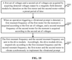
- a first set of voltages and a second set of voltages are acquired by acquiring detected voltages output by a magnetic field detector module by detection on the first motor and the second motor within a preset period of time.
- a first resonant frequency of the first motor for the moment is acquired according to the first set of voltages
- a second resonant frequency of the second motor for the moment is acquired according to the second set of voltages.
- the first resonant frequency and the second resonant frequency are sent to the drive module. Accordingly, the drive module drives, respectively according to the first resonant frequency and the second resonant frequency, the first motor and the second motor to vibrate synchronously to implement the vibrational prompt.
- the method may further include a block as follows.
- an input voltage of the first motor and an input voltage of the second motor may be acquired respectively.
- a result of comparison may be acquired by comparing the trends of changes in the input voltage of the first motor and the input voltage of the second motor.
- control signal may be generated according to the result of comparison.
- the control signal may be sent to the drive module.
- the drive module may drive, according to the control signal, the first motor and the second motor to keep vibrating synchronously.
- the method may further include a block as follows.
- an envelope signal of audio data may be acquired from an audio module in the electronic equipment.
- a drive signal may be generated according to the envelope signal.
- the drive signal may be sent to the drive module. Accordingly, the drive module may drive, according to the drive signal, at least one of the first motor or the second motor to vibrate with the audio data.
- a device for controlling a motor in electronic equipment may be based on the method for controlling a motor in electronic equipment.
- a device for controlling a motor in electronic equipment may include a voltage set acquiring module, a resonant frequency acquiring module, and a resonant frequency sending module.
- the voltage set acquiring portion 1301 may be adapted to acquiring a first set of voltages and a second set of voltages by acquiring detected voltages output by a magnetic field detector module by detection on the first motor and the second motor within a preset period of time.
- the resonant frequency acquiring portion 1302 may be adapted to, in response to detecting an operation triggering a vibrational prompt, acquiring a first resonant frequency of the first motor for the moment according to the first set of voltages, and acquiring a second resonant frequency of the second motor for the moment according to the second set of voltages.
- the resonant frequency sending portion 1303 may be adapted to sending the first resonant frequency and the second resonant frequency to the drive module. Accordingly, the drive module may drive, respectively according to the first resonant frequency and the second resonant frequency, the first motor and the second motor to vibrate synchronously to implement the vibrational prompt.
- the device may further include an input voltage acquiring module, a change trend acquiring module, a comparison result acquiring module, and a control signal generating module.
- the input voltage acquiring portion 1401 may be adapted to acquiring an input voltage of the first motor and an input voltage of the second motor respectively.
- the change trend acquiring portion 1402 may be adapted to acquiring trends of changes in the input voltage of the first motor and the input voltage of the second motor respectively.
- the comparison result acquiring portion 1403 may be adapted to acquiring a result of comparison by comparing the trends of changes in the input voltage of the first motor and the input voltage of the second motor.
- the control signal generating portion 1404 may be adapted to generating the control signal according to the result of comparison, and sending the control signal to the drive module. Accordingly, the drive module may drive, according to the control signal, the first motor and the second motor to keep vibrating synchronously.
- the device may further include an envelope signal acquiring module, a drive signal acquiring module, and a drive signal sending module.
- the envelope signal acquiring portion 1501 may be adapted to acquiring an envelope signal of audio data from an audio module in the electronic equipment.
- the drive signal acquiring portion 1502 may be adapted to generating a drive signal according to the envelope signal.
- the drive signal sending portion 1503 may be adapted to sending the drive signal to the drive module. Accordingly, the drive module may drive, according to the drive signal, at least one of the first motor or the second motor to vibrate with the audio data.
- a device for controlling a motor in electronic equipment includes a processor and memory.
- the memory is adapted to storing an instruction executable by the processor.
- the processor is adapted to implementing a method herein.
- a non-transitory computer-readable storage medium has stored thereon an executable instruction that, when executed by a processor, causes the processor to implement a method herein.
- FIG. 16 is a block diagram of electronic equipment according to some embodiments of the disclosure.
- the electronic equipment 1600 can be a mobile terminal such as a smart phone, a computer, digital broadcast UE, tablet equipment, medical equipment, fitness equipment, a Personal Digital Assistant, etc., that includes a circuit as shown in FIG. 1 through FIG. 9 .
- the electronic equipment 1600 may include one or more of a processing component 1602 , memory 1604 , a power supply component 1606 , a multimedia component 1608 , an audio component 1610 , an Input/Output (I/O) interface 1612 , a sensor component 1614 , a communication component 1616 , an image collecting component 1618 (not shown in the figure), etc.
- the processing component 1602 may generally control an overall operation of the electronic equipment 1600 , such as operations associated with display, a telephone call, data communication, a camera operation, a recording operation, etc.
- the processing component 1602 may include one or more processors 1620 to execute instructions so as to complete all or some blocks of the method.
- the processing component 1602 may include one or more modules to facilitate interaction between the processing component 1602 and other components.
- the processing component 1602 may include a multimedia module to facilitate interaction between the multimedia component 1608 and the processing component 1602 .
- the memory 1604 may be adapted to storing various types of data to support the operation at the electronic equipment 1600 . Examples of such data may include instructions of any application or method adapted to operating on the electronic equipment 1600 , contact data, phone book data, messages, pictures, videos, etc.
- the memory 1604 may be realized by any type of transitory or non-transitory storage equipment or combination thereof, such as Static Random-Access Memory (SRAM), Electrically Erasable Programmable Read-Only Memory (EEPROM), Erasable Programmable Read-Only Memory (EPROM), Programmable Read-Only Memory (PROM), Read-Only Memory (ROM), magnetic memory, flash memory, a magnetic disk, or a compact disk.
- SRAM Static Random-Access Memory
- EEPROM Electrically Erasable Programmable Read-Only Memory
- EPROM Erasable Programmable Read-Only Memory
- PROM Programmable Read-Only Memory
- ROM Read-Only Memory
- magnetic memory flash memory, a magnetic disk, or a compact disk.
- the power supply component 1606 may supply electric power to various components of the electronic equipment 1600 .
- the power supply component 1606 may include a power management system, one or more power sources, and other components related to generating, managing and distributing electricity for the electronic equipment 1600 .
- the multimedia component 1608 may include a screen providing an output interface between the electronic equipment 1600 and a target object.
- the screen may include a Liquid Crystal Display (LCD), and/or a Touch Panel (TP).
- LCD Liquid Crystal Display
- TP Touch Panel
- OLED organic light-emitting diode
- the screen may be realized as a touch screen to receive an input signal from a target object.
- the TP may include one or more touch sensors for sensing touch, slide and gestures on the TP. The touch sensors not only may sense the boundary of a touch or slide move, but also detect the duration and pressure related to the touch or slide move.
- the multimedia component 1608 may include a front camera and/or a rear camera.
- the front camera and/or the rear camera may receive external multimedia data.
- Each of the front camera or the rear camera may be a fixed optical lens system or may have a focal length and be capable of optical zooming.
- the audio component 1610 may be adapted to outputting and/or inputting an audio signal.
- the audio component 1610 may include a microphone (MIC).
- the MIC When the electronic equipment 1600 is in an operation mode such as a call mode, a recording mode, and a voice recognition mode, the MIC may be adapted to receiving an external audio signal.
- the received audio signal may be further stored in the memory 1604 or may be sent via the communication component 1616 .
- the audio component 1610 may further include a loudspeaker adapted to outputting the audio signal.
- the I/O interface 1612 may provide an interface between the processing component 1602 and a peripheral interface module.
- a peripheral interface module may be a keypad, a click wheel, a button, and/or the like.
- a button may include but is not limited to: a homepage button, a volume button, a start button, and a lock button.
- the sensor component 1614 may include one or more sensors for assessing various states of the electronic equipment 1600 .
- the sensor component 1614 may detect an on/off state of the electronic equipment 1600 and relative positioning of components such as the display and the keypad of the electronic equipment 1600 .
- the sensor component 1614 may further detect a change in the position of the electronic equipment 1600 or of a component of the electronic equipment, whether there is contact between the electronic equipment 1600 and a target object, the orientation or acceleration/deceleration of the electronic equipment 1600 , a change in the temperature of the electronic equipment 1600 .
- the sensor component 1614 may include a proximity sensor adapted to detecting existence of a nearby object without physical contact.
- the sensor component 1614 may further include an optical sensor such as a Complementary Metal-Oxide-Semiconductor (CMOS) or a Charge-Coupled-Device (CCD) image sensor used in an imaging application.
- CMOS Complementary Metal-Oxide-Semiconductor
- CCD Charge-Coupled-Device
- the sensor component 1614 may further include an acceleration sensor, a gyroscope sensor, a magnetic sensor, a distance sensor, a pressure sensor, or a temperature sensor.
- the communication component 1616 may be adapted to facilitating wired or wireless communication between the electronic equipment 1600 and other equipment.
- the electronic equipment 1600 may access a wireless network based on a communication standard such as Wi-Fi, 2G, 3G, 4G, 5G network or combination thereof.
- the communication component 1616 may broadcast related information or receive a broadcast signal from an external broadcast management system via a broadcast channel.
- the communication component 1616 may further include a Near Field Communication (NFC) module for short-range communication.
- the NFC module may be based on technology such as Radio Frequency Identification (RFID), Infrared Data Association (IrDA), Ultra-Wideband (UWB) technology, Bluetooth (BT), etc.
- RFID Radio Frequency Identification
- IrDA Infrared Data Association
- UWB Ultra-Wideband
- Bluetooth Bluetooth
- the electronic equipment 1600 may be realized by one or more electronic components such as an Application Specific Integrated Circuit (ASIC), a Digital Signal Processor (DSP), a Digital Signal Processing Device (DSPD), a Programmable Logic Device (PLD), a Field Programmable Gate Array (FPGA), a controller, a microcontroller, a microprocessor, etc., to implement the method.
- ASIC Application Specific Integrated Circuit
- DSP Digital Signal Processor
- DSPD Digital Signal Processing Device
- PLD Programmable Logic Device
- FPGA Field Programmable Gate Array
- controller a microcontroller, a microprocessor, etc.
- a non-transitory computer-readable storage medium including instructions such as memory 1604 including instructions, may be provided.
- the instructions may be executed by the processor 1620 of the electronic equipment 1600 , to implement the method.
- the computer-readable storage medium may be Read-Only Memory (ROM), Compact Disc Read-Only Memory (CD-ROM), a magnetic tape, a floppy disk, optical data storage equipment, and/or the like.
- the terms “installed,” “connected,” “coupled,” “fixed” and the like shall be understood broadly, and can be either a fixed connection or a detachable connection, or integrated, unless otherwise explicitly defined. These terms can refer to mechanical or electrical connections, or both. Such connections can be direct connections or indirect connections through an intermediate medium. These terms can also refer to the internal connections or the interactions between elements. The specific meanings of the above terms in the present disclosure can be understood by those of ordinary skill in the art on a case-by-case basis.
- the terms “one embodiment,” “some embodiments,” “example,” “specific example,” or “some examples,” and the like can indicate a specific feature described in connection with the embodiment or example, a structure, a material or feature included in at least one embodiment or example.
- the schematic representation of the above terms is not necessarily directed to the same embodiment or example.
- first and second are used for descriptive purposes only and are not to be construed as indicating or implying a relative importance or implicitly indicating the number of technical features indicated. Thus, elements referred to as “first” and “second” may include one or more of the features either explicitly or implicitly. In the description of the present disclosure, “a plurality” indicates two or more unless specifically defined otherwise.
- a first element being “on” a second element may indicate direct contact between the first and second elements, without contact, or indirect geometrical relationship through one or more intermediate media or layers, unless otherwise explicitly stated and defined.
- a first element being “under,” “underneath” or “beneath” a second element may indicate direct contact between the first and second elements, without contact, or indirect geometrical relationship through one or more intermediate media or layers, unless otherwise explicitly stated and defined.
- a term “and/or” may describe an association between associated objects, including three possible relationships.
- a and/or B it may mean that there may be three cases, namely, existence of but A, existence of both A and B, or existence of but B.
- a slash mark “/” may generally denote an “or” relationship between two associated objects that come respectively before and after the mark per se.
Landscapes
- Engineering & Computer Science (AREA)
- General Engineering & Computer Science (AREA)
- Theoretical Computer Science (AREA)
- Human Computer Interaction (AREA)
- Power Engineering (AREA)
- Physics & Mathematics (AREA)
- General Physics & Mathematics (AREA)
- Signal Processing (AREA)
- Computer Networks & Wireless Communication (AREA)
- Audiology, Speech & Language Pathology (AREA)
- General Health & Medical Sciences (AREA)
- Health & Medical Sciences (AREA)
- Apparatuses For Generation Of Mechanical Vibrations (AREA)
- User Interface Of Digital Computer (AREA)
- Control Of Multiple Motors (AREA)
- Automatic Disk Changers (AREA)
- Control Of Electric Motors In General (AREA)
Abstract
Description
Vout=Vin/(1−D)
Moreover, according to some embodiments, the in-phase circuit may increase a signal-to-noise ratio.
Claims (19)
Applications Claiming Priority (2)
| Application Number | Priority Date | Filing Date | Title |
|---|---|---|---|
| CN201911184534.3A CN112865612B (en) | 2019-11-27 | 2019-11-27 | Electronic device, control method and device thereof, and readable storage medium |
| CN201911184534.3 | 2019-11-27 |
Publications (2)
| Publication Number | Publication Date |
|---|---|
| US20210160364A1 US20210160364A1 (en) | 2021-05-27 |
| US11652915B2 true US11652915B2 (en) | 2023-05-16 |
Family
ID=69953873
Family Applications (1)
| Application Number | Title | Priority Date | Filing Date |
|---|---|---|---|
| US16/814,907 Active 2041-04-08 US11652915B2 (en) | 2019-11-27 | 2020-03-10 | Electronic equipment, control method and device thereof, and readable storage medium |
Country Status (6)
| Country | Link |
|---|---|
| US (1) | US11652915B2 (en) |
| EP (1) | EP3829145B1 (en) |
| JP (1) | JP7558061B2 (en) |
| KR (1) | KR102419658B1 (en) |
| CN (1) | CN112865612B (en) |
| WO (1) | WO2021103311A1 (en) |
Families Citing this family (10)
| Publication number | Priority date | Publication date | Assignee | Title |
|---|---|---|---|---|
| WO2019094440A1 (en) * | 2017-11-08 | 2019-05-16 | General Vibration Corporation | Coherent phase switching and modulation of a linear actuator array |
| CN115473961B (en) * | 2021-06-11 | 2024-07-16 | 华为技术有限公司 | Vibration control method, electronic device, storage medium and computer program product |
| CN113840023B (en) * | 2021-09-13 | 2024-04-02 | 维沃移动通信有限公司 | Electronic equipment, control method and control device |
| CN113992106B (en) * | 2021-10-29 | 2024-07-02 | 歌尔股份有限公司 | Motor control method, apparatus, device, and computer-readable storage medium |
| CN114123848B (en) * | 2021-11-23 | 2024-01-30 | 歌尔股份有限公司 | Control method and control device of multi-dimensional three-dimensional vibration device |
| CN114221596B (en) * | 2021-12-22 | 2023-12-22 | 歌尔股份有限公司 | Method, apparatus and computer readable storage medium for adjusting vibration feeling based on motor |
| CN115357124B (en) * | 2022-09-20 | 2023-09-05 | 武汉市聚芯微电子有限责任公司 | Vibration control method, device, equipment and storage medium |
| CN116045731A (en) * | 2022-11-17 | 2023-05-02 | 福建清流汽枪厂有限公司 | Electric gun state prompting device |
| CN116699388B (en) * | 2022-11-22 | 2024-05-24 | 荣耀终端有限公司 | Linear motor calibration method and electronic equipment |
| CN117811414A (en) * | 2023-12-06 | 2024-04-02 | 歌尔股份有限公司 | Driving circuit of vibration device and electronic equipment |
Citations (26)
| Publication number | Priority date | Publication date | Assignee | Title |
|---|---|---|---|---|
| JPS63123476A (en) | 1986-11-12 | 1988-05-27 | 株式会社カイジョー | Ultrasonic washer |
| JPH02265681A (en) | 1989-04-07 | 1990-10-30 | Olympus Optical Co Ltd | Ultrasonic converter driving circuit |
| JPH09201079A (en) | 1996-01-18 | 1997-07-31 | Nikon Corp | Linked vibrating actuator and its drive device |
| JP2001054259A (en) | 1999-08-04 | 2001-02-23 | C I Kasei Co Ltd | Spring conductor, end plate for attaching spring conductor, end plate assembly, and vibration generator in micro brush motor |
| JP2001121079A (en) | 1999-10-22 | 2001-05-08 | Yamaha Corp | Apparatus for driving vibration source |
| JP2004267936A (en) | 2003-03-10 | 2004-09-30 | Yamaha Corp | Vibrator operation circuit |
| EP2012422A1 (en) | 2007-07-03 | 2009-01-07 | Seiko Epson Corporation | Drive control circuit for electric motor |
| EP2339427A2 (en) | 2009-12-24 | 2011-06-29 | Samsung Electronics Co., Ltd. | Method and apparatus for generating vibrations in portable terminal |
| JP2011152533A (en) | 2010-01-28 | 2011-08-11 | Sanyo Electric Co Ltd | Drive control circuit of linear vibration motor |
| JP2013050920A (en) | 2011-08-31 | 2013-03-14 | Minebea Co Ltd | Input device |
| US20130182878A1 (en) * | 2012-01-12 | 2013-07-18 | Lin Liu | Vibration Speaker |
| CN105549777A (en) | 2015-12-04 | 2016-05-04 | 联想(北京)有限公司 | Electronic equipment and control method |
| CN106254580A (en) | 2016-07-18 | 2016-12-21 | 青岛海信移动通信技术股份有限公司 | Mobile terminal |
| CN106849781A (en) | 2017-03-31 | 2017-06-13 | 珠海市魅族科技有限公司 | A kind of motor drive circuit, method and electronic equipment |
| KR20170081727A (en) | 2014-12-31 | 2017-07-12 | 주식회사 소니 인터랙티브 엔터테인먼트 | Signal generation and detector systems and methods for determining positions of fingers of a user |
| US20180026572A1 (en) * | 2016-07-21 | 2018-01-25 | AAC Technologies Pte. Ltd. | Vibration Conformance Compensation Device and Compensation Method Thereof |
| CN108347525A (en) | 2018-01-12 | 2018-07-31 | 广东欧珀移动通信有限公司 | Electronic equipment vibration control method and device and electronic equipment |
| CN108683761A (en) | 2018-05-17 | 2018-10-19 | Oppo广东移动通信有限公司 | Sound production control method and device, electronic device and computer readable medium |
| CN208820835U (en) | 2018-10-30 | 2019-05-03 | Oppo广东移动通信有限公司 | Electronic equipment |
| CN109756159A (en) | 2019-02-21 | 2019-05-14 | 信利光电股份有限公司 | A kind of linear motor group vibrational system, control method and electronic equipment |
| CN109901703A (en) | 2017-12-11 | 2019-06-18 | 北京小米移动软件有限公司 | The method for oscillating and storage medium of a kind of terminal, terminal |
| JP2019130462A (en) | 2018-01-30 | 2019-08-08 | 日本電産セイミツ株式会社 | Vibration device, vibratory equipment, and method for control of vibration device |
| CN209313874U (en) | 2018-12-29 | 2019-08-27 | 瑞声科技(南京)有限公司 | Mobile terminal |
| KR20190100832A (en) | 2018-02-21 | 2019-08-29 | 주식회사 이엠텍 | Hybrid actuator and multimedia apparatus having the same |
| CN110266856A (en) | 2019-06-28 | 2019-09-20 | Oppo(重庆)智能科技有限公司 | Electronic equipment and vibration device, method |
| CN110312038A (en) | 2019-06-28 | 2019-10-08 | Oppo(重庆)智能科技有限公司 | Information cuing method and device, electronic equipment, computer readable storage medium |
-
2019
- 2019-11-27 CN CN201911184534.3A patent/CN112865612B/en active Active
-
2020
- 2020-02-03 JP JP2020515683A patent/JP7558061B2/en active Active
- 2020-02-03 WO PCT/CN2020/074179 patent/WO2021103311A1/en active Application Filing
- 2020-02-03 KR KR1020207007403A patent/KR102419658B1/en active Active
- 2020-03-10 US US16/814,907 patent/US11652915B2/en active Active
- 2020-03-23 EP EP20164886.2A patent/EP3829145B1/en active Active
Patent Citations (36)
| Publication number | Priority date | Publication date | Assignee | Title |
|---|---|---|---|---|
| JPS63123476A (en) | 1986-11-12 | 1988-05-27 | 株式会社カイジョー | Ultrasonic washer |
| JPH02265681A (en) | 1989-04-07 | 1990-10-30 | Olympus Optical Co Ltd | Ultrasonic converter driving circuit |
| JPH09201079A (en) | 1996-01-18 | 1997-07-31 | Nikon Corp | Linked vibrating actuator and its drive device |
| JP2001054259A (en) | 1999-08-04 | 2001-02-23 | C I Kasei Co Ltd | Spring conductor, end plate for attaching spring conductor, end plate assembly, and vibration generator in micro brush motor |
| JP2001121079A (en) | 1999-10-22 | 2001-05-08 | Yamaha Corp | Apparatus for driving vibration source |
| JP2004267936A (en) | 2003-03-10 | 2004-09-30 | Yamaha Corp | Vibrator operation circuit |
| US20120007538A1 (en) | 2007-07-03 | 2012-01-12 | Seiko Epson Corporation | Robot |
| EP2012422A1 (en) | 2007-07-03 | 2009-01-07 | Seiko Epson Corporation | Drive control circuit for electric motor |
| US20090009118A1 (en) * | 2007-07-03 | 2009-01-08 | Seiko Epson Corporation | Drive control circuit for electric motor |
| US20110157052A1 (en) * | 2009-12-24 | 2011-06-30 | Samsung Electronics Co., Ltd. | Method and apparatus for generating vibrations in portable terminal |
| KR20110074333A (en) | 2009-12-24 | 2011-06-30 | 삼성전자주식회사 | Method and apparatus for generating vibration of a mobile terminal |
| EP2339427A2 (en) | 2009-12-24 | 2011-06-29 | Samsung Electronics Co., Ltd. | Method and apparatus for generating vibrations in portable terminal |
| JP2011152533A (en) | 2010-01-28 | 2011-08-11 | Sanyo Electric Co Ltd | Drive control circuit of linear vibration motor |
| JP2013050920A (en) | 2011-08-31 | 2013-03-14 | Minebea Co Ltd | Input device |
| US20130182878A1 (en) * | 2012-01-12 | 2013-07-18 | Lin Liu | Vibration Speaker |
| US9148716B2 (en) | 2012-01-12 | 2015-09-29 | Aac Acoustic Technologies (Shenzhen) Co., Ltd. | Vibration speaker |
| US20150289043A1 (en) | 2012-01-12 | 2015-10-08 | Aac Acoustic Technologies (Shenzhen) Co., Ltd. | Vibration speaker |
| US9591391B2 (en) | 2012-01-12 | 2017-03-07 | Aac Acoustic Technologies (Shenzhen) Co., Ltd. | Vibration speaker |
| KR20170081727A (en) | 2014-12-31 | 2017-07-12 | 주식회사 소니 인터랙티브 엔터테인먼트 | Signal generation and detector systems and methods for determining positions of fingers of a user |
| CN105549777A (en) | 2015-12-04 | 2016-05-04 | 联想(北京)有限公司 | Electronic equipment and control method |
| US20170160806A1 (en) | 2015-12-04 | 2017-06-08 | Lenovo (Beijing) Limited | Electronic device, method and computer program product for providing vibratory feedback |
| US10152129B2 (en) | 2015-12-04 | 2018-12-11 | Lenovo (Beijing) Limited | Electronic device, method and computer program product for providing vibratory feedback |
| CN106254580A (en) | 2016-07-18 | 2016-12-21 | 青岛海信移动通信技术股份有限公司 | Mobile terminal |
| CN106254580B (en) | 2016-07-18 | 2019-06-04 | 青岛海信移动通信技术股份有限公司 | Mobile terminal |
| US20180026572A1 (en) * | 2016-07-21 | 2018-01-25 | AAC Technologies Pte. Ltd. | Vibration Conformance Compensation Device and Compensation Method Thereof |
| CN106849781A (en) | 2017-03-31 | 2017-06-13 | 珠海市魅族科技有限公司 | A kind of motor drive circuit, method and electronic equipment |
| CN109901703A (en) | 2017-12-11 | 2019-06-18 | 北京小米移动软件有限公司 | The method for oscillating and storage medium of a kind of terminal, terminal |
| CN108347525A (en) | 2018-01-12 | 2018-07-31 | 广东欧珀移动通信有限公司 | Electronic equipment vibration control method and device and electronic equipment |
| JP2019130462A (en) | 2018-01-30 | 2019-08-08 | 日本電産セイミツ株式会社 | Vibration device, vibratory equipment, and method for control of vibration device |
| KR20190100832A (en) | 2018-02-21 | 2019-08-29 | 주식회사 이엠텍 | Hybrid actuator and multimedia apparatus having the same |
| CN108683761A (en) | 2018-05-17 | 2018-10-19 | Oppo广东移动通信有限公司 | Sound production control method and device, electronic device and computer readable medium |
| CN208820835U (en) | 2018-10-30 | 2019-05-03 | Oppo广东移动通信有限公司 | Electronic equipment |
| CN209313874U (en) | 2018-12-29 | 2019-08-27 | 瑞声科技(南京)有限公司 | Mobile terminal |
| CN109756159A (en) | 2019-02-21 | 2019-05-14 | 信利光电股份有限公司 | A kind of linear motor group vibrational system, control method and electronic equipment |
| CN110266856A (en) | 2019-06-28 | 2019-09-20 | Oppo(重庆)智能科技有限公司 | Electronic equipment and vibration device, method |
| CN110312038A (en) | 2019-06-28 | 2019-10-08 | Oppo(重庆)智能科技有限公司 | Information cuing method and device, electronic equipment, computer readable storage medium |
Non-Patent Citations (7)
| Title |
|---|
| Choi, Dong-Soo; "Haptic Rendering Method using Beat Phenomenon a Transparent Film-type Actuator Array", Korea University of Technology Education, Feb. 2015. |
| First Office Action after Appeal of the Korean application No. 10-2020-7007403, dated Dec. 30, 2021. |
| First Office Action of the Chinese application No. 201911184534.3, dated Jul. 26, 2022. |
| First Office Action of the Japanese application No. 2020-515683, dated Feb. 22, 2022. |
| International Search Report in the international application No. PCT/CN2020/074179, dated Aug. 27, 2020. |
| Office Action ofthe Indian application No. 202047012839, dated Oct. 11, 2022. |
| Supplementary European Search Report in the European application No. 20164886.2, dated Jul. 29, 2020. |
Also Published As
| Publication number | Publication date |
|---|---|
| KR20210068315A (en) | 2021-06-09 |
| CN112865612A (en) | 2021-05-28 |
| EP3829145A1 (en) | 2021-06-02 |
| EP3829145B1 (en) | 2023-09-27 |
| JP2022514994A (en) | 2022-02-17 |
| US20210160364A1 (en) | 2021-05-27 |
| JP7558061B2 (en) | 2024-09-30 |
| CN112865612B (en) | 2023-05-16 |
| KR102419658B1 (en) | 2022-07-08 |
| WO2021103311A1 (en) | 2021-06-03 |
Similar Documents
| Publication | Publication Date | Title |
|---|---|---|
| US11652915B2 (en) | Electronic equipment, control method and device thereof, and readable storage medium | |
| CN106462240B (en) | For providing touch feedback with the system and method for aided capture image | |
| CN106461727B (en) | Control method and device, the electronic equipment of motor vibrations | |
| KR101900405B1 (en) | Method and device for charge management, program and recording medium | |
| US10448170B2 (en) | Sound generator and sound generation system | |
| CN110086992A (en) | Filming control method, mobile terminal and the computer storage medium of mobile terminal | |
| KR20140137848A (en) | Apparatus and method for providing battery information and user termial | |
| CN105100897B (en) | The control method and device fast played | |
| CN111262989B (en) | Notification reminding method and device and storage medium | |
| EP3016236A1 (en) | Power supply circuit and electronic equipment | |
| JP2010035297A (en) | Charging unit, electronic equipment, imaging apparatus, and charging device | |
| CN106295468B (en) | Face identification method and device | |
| EP3757722A1 (en) | Information processing device, information processing method, and computer program | |
| JP4446781B2 (en) | Digital camera | |
| CN112367463B (en) | Camera module control circuit, method and electronic device | |
| EP3823314A1 (en) | User equipment and method for outputting audio | |
| CN105635378A (en) | Call quality adjusting method, device and mobile terminal | |
| CN107395887A (en) | A kind of device and method for being used to carry out speech play and vibration | |
| KR101889702B1 (en) | Method for correcting user’s hand tremor, machine-readable storage medium and imaging device | |
| CN114499739A (en) | Magnetic field signal processing method, device and storage medium | |
| CN113885693A (en) | Touch feedback module and method, electronic device, computer storage medium | |
| CN112748436B (en) | Electronic device, distance detection method and device, and storage medium | |
| CN112748337A (en) | Electronic equipment, method and device for controlling motor in electronic equipment | |
| JP2017147480A (en) | Imaging apparatus and input control method | |
| CN118748753A (en) | Camera anti-shake method, camera module and electronic equipment |
Legal Events
| Date | Code | Title | Description |
|---|---|---|---|
| AS | Assignment |
Owner name: BEIJING XIAOMI MOBILE SOFTWARE CO., LTD., CHINA Free format text: ASSIGNMENT OF ASSIGNORS INTEREST;ASSIGNOR:CHEN, CHAOXI;REEL/FRAME:052074/0241 Effective date: 20200302 |
|
| FEPP | Fee payment procedure |
Free format text: ENTITY STATUS SET TO UNDISCOUNTED (ORIGINAL EVENT CODE: BIG.); ENTITY STATUS OF PATENT OWNER: LARGE ENTITY |
|
| STPP | Information on status: patent application and granting procedure in general |
Free format text: DOCKETED NEW CASE - READY FOR EXAMINATION |
|
| STPP | Information on status: patent application and granting procedure in general |
Free format text: NON FINAL ACTION MAILED |
|
| STPP | Information on status: patent application and granting procedure in general |
Free format text: RESPONSE TO NON-FINAL OFFICE ACTION ENTERED AND FORWARDED TO EXAMINER |
|
| STPP | Information on status: patent application and granting procedure in general |
Free format text: NOTICE OF ALLOWANCE MAILED -- APPLICATION RECEIVED IN OFFICE OF PUBLICATIONS |
|
| STPP | Information on status: patent application and granting procedure in general |
Free format text: AWAITING TC RESP., ISSUE FEE NOT PAID |
|
| STPP | Information on status: patent application and granting procedure in general |
Free format text: NOTICE OF ALLOWANCE MAILED -- APPLICATION RECEIVED IN OFFICE OF PUBLICATIONS |
|
| STPP | Information on status: patent application and granting procedure in general |
Free format text: PUBLICATIONS -- ISSUE FEE PAYMENT VERIFIED |
|
| STPP | Information on status: patent application and granting procedure in general |
Free format text: WITHDRAW FROM ISSUE AWAITING ACTION |
|
| STCF | Information on status: patent grant |
Free format text: PATENTED CASE |