US11652375B2 - Stator and method for manufacturing the same - Google Patents

Stator and method for manufacturing the same Download PDF

Info

Publication number
US11652375B2
US11652375B2 US17/039,860 US202017039860A US11652375B2 US 11652375 B2 US11652375 B2 US 11652375B2 US 202017039860 A US202017039860 A US 202017039860A US 11652375 B2 US11652375 B2 US 11652375B2
Authority
US
United States
Prior art keywords
stator
insulating part
insulating
stator coils
joint
Prior art date
Legal status (The legal status is an assumption and is not a legal conclusion. Google has not performed a legal analysis and makes no representation as to the accuracy of the status listed.)
Active, expires
Application number
US17/039,860
Other versions
US20210296947A1 (en
Inventor
Hojun SHIN
Wonjung SUNG
Gyeongjae PARK
Jeongmin Lee
Current Assignee (The listed assignees may be inaccurate. Google has not performed a legal analysis and makes no representation or warranty as to the accuracy of the list.)
LG Magna E Powertrain Co Ltd
Original Assignee
LG Magna E Powertrain Co Ltd
Priority date (The priority date is an assumption and is not a legal conclusion. Google has not performed a legal analysis and makes no representation as to the accuracy of the date listed.)
Filing date
Publication date
Application filed by LG Magna E Powertrain Co Ltd filed Critical LG Magna E Powertrain Co Ltd
Assigned to LG ELECTRONICS INC. reassignment LG ELECTRONICS INC. ASSIGNMENT OF ASSIGNORS INTEREST (SEE DOCUMENT FOR DETAILS). Assignors: LEE, JEONGMIN, PARK, Gyeongjae, SHIN, HOJUN, SUNG, Wonjung
Assigned to LG MAGNA E-POWERTRAIN CO., LTD. reassignment LG MAGNA E-POWERTRAIN CO., LTD. ASSIGNMENT OF ASSIGNORS INTEREST (SEE DOCUMENT FOR DETAILS). Assignors: LG ELECTRONICS INC.
Publication of US20210296947A1 publication Critical patent/US20210296947A1/en
Application granted granted Critical
Publication of US11652375B2 publication Critical patent/US11652375B2/en
Active legal-status Critical Current
Adjusted expiration legal-status Critical

Links

Images

Classifications

    • HELECTRICITY
    • H02GENERATION; CONVERSION OR DISTRIBUTION OF ELECTRIC POWER
    • H02KDYNAMO-ELECTRIC MACHINES
    • H02K3/00Details of windings
    • H02K3/32Windings characterised by the shape, form or construction of the insulation
    • H02K3/38Windings characterised by the shape, form or construction of the insulation around winding heads, equalising connectors, or connections thereto
    • HELECTRICITY
    • H02GENERATION; CONVERSION OR DISTRIBUTION OF ELECTRIC POWER
    • H02KDYNAMO-ELECTRIC MACHINES
    • H02K1/00Details of the magnetic circuit
    • H02K1/06Details of the magnetic circuit characterised by the shape, form or construction
    • H02K1/12Stationary parts of the magnetic circuit
    • H02K1/16Stator cores with slots for windings
    • H02K1/165Shape, form or location of the slots
    • HELECTRICITY
    • H02GENERATION; CONVERSION OR DISTRIBUTION OF ELECTRIC POWER
    • H02KDYNAMO-ELECTRIC MACHINES
    • H02K15/00Processes or apparatus specially adapted for manufacturing, assembling, maintaining or repairing of dynamo-electric machines
    • H02K15/02Processes or apparatus specially adapted for manufacturing, assembling, maintaining or repairing of dynamo-electric machines of stator or rotor bodies
    • H02K15/021Magnetic cores
    • H02K15/024
    • HELECTRICITY
    • H02GENERATION; CONVERSION OR DISTRIBUTION OF ELECTRIC POWER
    • H02KDYNAMO-ELECTRIC MACHINES
    • H02K15/00Processes or apparatus specially adapted for manufacturing, assembling, maintaining or repairing of dynamo-electric machines
    • H02K15/10Applying solid insulation to windings, stators or rotors, e.g. applying insulating tapes
    • H02K15/105Applying solid insulation to windings, stators or rotors, e.g. applying insulating tapes to the windings
    • HELECTRICITY
    • H02GENERATION; CONVERSION OR DISTRIBUTION OF ELECTRIC POWER
    • H02KDYNAMO-ELECTRIC MACHINES
    • H02K15/00Processes or apparatus specially adapted for manufacturing, assembling, maintaining or repairing of dynamo-electric machines
    • H02K15/12Impregnating, moulding insulation, heating or drying of windings, stators, rotors or machines
    • HELECTRICITY
    • H02GENERATION; CONVERSION OR DISTRIBUTION OF ELECTRIC POWER
    • H02KDYNAMO-ELECTRIC MACHINES
    • H02K15/00Processes or apparatus specially adapted for manufacturing, assembling, maintaining or repairing of dynamo-electric machines
    • H02K15/30Manufacture of winding connections
    • H02K15/33Connecting winding sections; Forming leads; Connecting leads to terminals
    • HELECTRICITY
    • H02GENERATION; CONVERSION OR DISTRIBUTION OF ELECTRIC POWER
    • H02KDYNAMO-ELECTRIC MACHINES
    • H02K3/00Details of windings
    • H02K3/04Windings characterised by the conductor shape, form or construction, e.g. with bar conductors
    • H02K3/12Windings characterised by the conductor shape, form or construction, e.g. with bar conductors arranged in slots
    • HELECTRICITY
    • H02GENERATION; CONVERSION OR DISTRIBUTION OF ELECTRIC POWER
    • H02KDYNAMO-ELECTRIC MACHINES
    • H02K3/00Details of windings
    • H02K3/04Windings characterised by the conductor shape, form or construction, e.g. with bar conductors
    • H02K3/28Layout of windings or of connections between windings
    • HELECTRICITY
    • H02GENERATION; CONVERSION OR DISTRIBUTION OF ELECTRIC POWER
    • H02KDYNAMO-ELECTRIC MACHINES
    • H02K3/00Details of windings
    • H02K3/30Windings characterised by the insulating material
    • HELECTRICITY
    • H02GENERATION; CONVERSION OR DISTRIBUTION OF ELECTRIC POWER
    • H02KDYNAMO-ELECTRIC MACHINES
    • H02K3/00Details of windings
    • H02K3/32Windings characterised by the shape, form or construction of the insulation
    • H02K3/34Windings characterised by the shape, form or construction of the insulation between conductors or between conductor and core, e.g. slot insulation
    • H02K3/345Windings characterised by the shape, form or construction of the insulation between conductors or between conductor and core, e.g. slot insulation between conductor and core, e.g. slot insulation
    • HELECTRICITY
    • H02GENERATION; CONVERSION OR DISTRIBUTION OF ELECTRIC POWER
    • H02KDYNAMO-ELECTRIC MACHINES
    • H02K3/00Details of windings
    • H02K3/46Fastening of windings on the stator or rotor structure
    • H02K3/50Fastening of winding heads, equalising connectors, or connections thereto
    • H02K3/505Fastening of winding heads, equalising connectors, or connections thereto for large machine windings, e.g. bar windings

Definitions

  • the present disclosure relates to a stator including a stator coil having ends to be joined.
  • An electric motor is an electrical machine that generates a rotational force using electrical energy.
  • Most electric motors include a housing, a stator disposed inside the housing, and a rotor disposed inside the stator and rotated by a magnetic field generated in the stator.
  • the stator may include a stator core and a plurality of stator coils respectively wound around the stator core.
  • each of the stator coils may be wound on the stator core in a U-shape to have two ends adjacent to each other. For electric connection, the two adjacent ends of each of the stator coils may be welded together to form one end.
  • Welded ends of the plurality of stator coils may be spaced apart from one another in a radial direction of the stator core by a predetermined interval (or gap).
  • a partial discharge may occur in the ends of the stator coils caused by a surge due to a large potential difference therebetween, as the electric motor is driven by a high voltage.
  • a minimum distance for preventing the surge between the ends of the stator coils may be secured.
  • a measure for securely maintaining a predetermined distance between the ends of the stator coils may be considered.
  • stator In the related art stator, a stator manufacturing process that includes epoxy coating (or application) performed on welded ends of stator coils for insulation has been introduced.
  • epoxy coating or application
  • such epoxy coating on the welded ends of the stator coils has drawbacks. For instance, it may be difficult to evenly or uniformly apply liquid or powder epoxy to each of the ends of the stator coils, and thus some areas (or portions) may not be properly coated with epoxy. As a result, operational reliability of the stator may be reduced.
  • One aspect of the present disclosure is to provide a stator capable of maintaining a distance between welded joint ends of stator coils.
  • Another aspect of the present disclosure is to provide a stator capable of securely maintaining a coupled state between an insulating part, provided on ends of stator coils for insulation, and the ends of the stator coils.
  • Still another aspect of the present disclosure is to provide a stator capable of eliminating epoxy coating (or application), which is performed for insulating ends of stator coils, from the conventional stator manufacturing process.
  • Embodiments disclosed herein provide a stator that may include: a stator core having a plurality of slots; a plurality of stator coils inserted into the plurality of slots to be wound on the stator core, and each having two ends electrically connected to form one joint portion; an insulating part made of a dielectric material, formed as a single body, having a plurality of openings, inserted into each of the joint portions through the openings to cover at least respective parts of the joint portions, and configured to provide a distance between neighboring joint portions.
  • the openings may be provided at one side of the insulating part, and the insulating part may have a shape in which an opposite side of the one side where the openings are provided is closed.
  • Each of the stator coils may include a first conductor and a second conductor through which electric current flows and defining the two ends of the stator coil, respectively, and covering portions designed to cover respective parts of the first and second conductors, excluding the joint portion, to provide protection.
  • the insulating part may partially cover the covering portions.
  • the insulating part may further include a support portion protruding from an inner surface thereof and configured to be elastically deformable.
  • the support portion may be disposed at a position that faces the covering portion while the insulating part is inserted into the joint portion, and pressed by the covering portion to be supported thereon.
  • the support portion may be disposed at a position that faces at least one of the first and second conductors while the insulating part is inserted into the joint portion, and pressed by at least one of the first and second conductors to be supported on the at least one of the first and second conductors.
  • the support portion may have a hemisphere shape.
  • the support portion may extend on an inner surface of the insulating part along a perimeter of the insulating part.
  • the insulating part may further include a plurality of accommodation spaces partitioned from each other and inserted into each of the joint portions.
  • Each of the accommodation spaces may have a first inner diameter defining an area that surrounds the joint portion and a second inner diameter defining an area that surrounds the covering portions, so that the insulating part is engagingly supported by the covering portions while being inserted into the joint portion.
  • the insulating part may include a first insulating portion and a second insulating portion made of different types of dielectric materials.
  • the first insulating portion may define any one portion of the insulating part, and the second insulating portion may define another portion of the insulating part.
  • the first insulating portion may define an inner side of the insulating part and have a first elastic force
  • the second insulating portion may define an outer side of the insulating part and have a second elastic force less than the first elastic force
  • the insulating part may further include an adhesive layer provided on an inner surface thereof and implemented as an adhesive.
  • the insulating part may include a first portion defining an upper surface thereof, and a second portion defining a side surface thereof.
  • a thickness of the first portion may be less than a thickness of the second portion.
  • the dialectic material may have a dielectric constant of 3 to 5.
  • the dielectric material may include at least one of Polyimide (PI), Polyamideimide (PAI), and Polyetheretherketone (PEEK).
  • PI Polyimide
  • PAI Polyamideimide
  • PEEK Polyetheretherketone
  • the plurality of stator coils may be spaced apart from one another along a circumference of the stator core by a predetermined interval.
  • the insulating part may have a ring shape to cover all of the joint portions of the plurality of stator coils.
  • Embodiments disclosed herein also provide a method for manufacturing a stator, the method may include: welding two ends of each of stator coils wound on a stator core to form one joint portion; inserting an insulating part, made of a dietetic material, formed as a single body, and provided with a plurality of openings, into the joint portions through the openings to be fixed; impregnating a coating material into the stator coils to form a film thereon; and curing the coating material impregnated into the stator coils.
  • the coating material impregnated into the stator coils and cured may be varnish.
  • FIG. 1 A is a perspective view illustrating a state in which an insulating part is separated from a stator according to one embodiment of the present disclosure.
  • FIG. 1 B is a perspective view illustrating a state in which an insulating part is coupled to an end of a stator coil in FIG. 1 A .
  • FIG. 2 is an enlarged view schematically illustrating a state in which an insulating part is coupled to an end of a stator coil in FIG. 1 A .
  • FIG. 3 A is a perspective view of the insulating part in FIG. 1 A , viewed from above.
  • FIG. 3 B is a perspective view of the insulating part in FIG. 1 A , viewed from the bottom.
  • FIG. 4 is an enlarged view illustrating a portion of the insulating part in FIG. 3 B .
  • FIG. 5 is a schematic view illustrating a state in which an insulating part is coupled to an end of a stator coil in FIG. 1 A .
  • FIG. 6 is a schematic view illustrating a portion of an insulating part for explaining a structure of the insulating part coupled to an end of a stator coil in FIG. 1 A .
  • FIG. 7 is a schematic view illustrating another example of the insulating part in FIG. 6 .
  • FIG. 8 is a schematic view illustrating another example of the insulating part in FIG. 6 .
  • FIG. 9 is a schematic view illustrating another example of the insulating part in FIG. 6 .
  • FIG. 10 is a schematic view illustrating another example of the insulating part in FIG. 6 .
  • FIG. 11 is a schematic view illustrating another example of the insulating part in FIG. 6 , viewed from the bottom.
  • FIG. 12 is a flowchart of a method of manufacturing the stator in FIGS. 1 A and 1 B .
  • a singular representation may include a plural representation unless it represents a definitely different meaning from the context.
  • FIG. 1 A is a perspective view illustrating a state in which an insulating part 130 is separated from a stator 100 according to one embodiment of the present disclosure
  • FIG. 1 B is a perspective view illustrating a state in which the insulating part 130 is coupled to an end of a stator coil 120 in FIG. 1 A
  • FIG. 2 is an enlarged view schematically illustrating a state in which the insulating part 130 is coupled to the end of the stator coil 120 in FIG. 1 A
  • FIG. 3 A is a perspective view of the insulating part 130 in FIG. 1 , viewed from above
  • FIG. 3 B is a perspective view of the insulating part 130 in FIG. 1 A , viewed from the bottom;
  • FIG. 1 A is a perspective view illustrating a state in which an insulating part 130 is separated from a stator 100 according to one embodiment of the present disclosure
  • FIG. 1 B is a perspective view illustrating a state in which the insulating part 130 is coupled to an end of a stator coil
  • FIG. 4 is an enlarged view illustrating a portion of the insulating part 130 in FIG. 3 B ;
  • FIG. 5 is a schematic view illustrating a state in which the illustrating part 130 is coupled to the end of the stator coil 120 in FIG. 1 A ;
  • FIG. 6 is a schematic view illustrating a portion of the insulating part 130 for explaining a structure of the insulating part 130 coupled to the end of the stator coil 120 in FIG. 1 A .
  • the stator 100 includes a stator core 110 , the stator coil 120 , and the insulating part 130 .
  • the stator core 110 is provided with a plurality of slots 111 through which a plurality of stator coils 120 , which will be described hereinafter, is wound.
  • a rotor (not shown) may be disposed inside the stator core 110 .
  • the rotor (not shown) may be configured to rotate in one direction by a rotating magnetic field generated in the stator 100 .
  • Each of the stator coils 120 may be inserted into the plurality of the slots 111 to be wound on the stator core 110 , and two ends thereof may be electrically connected to form one joint (or junction) portion 120 a .
  • the joint portion 120 a may be achieved or formed by welding.
  • the stator coil 120 may be provided in plurality.
  • Each of the stator coils 120 may be formed in, for example, a U-shape to be wound around the stator core 110 .
  • the two ends of the stator coil 120 may be made of bare copper that is uncoated.
  • the stator coil 120 may include a first conductor 121 a , a second conductor 121 b , and covering portions (or sheath) 122 .
  • the first conductor 121 a and the second conductor 121 b are made of an electrically conductive material, so as to allow an electric current to flow therethrough.
  • the first conductor 121 a and the second conductor 121 b may define the two ends of the stator coil 120 , respectively.
  • the covering portions 122 may cover respective parts or portions of the first and second conductors 121 a and 121 b , excluding the joint portion 120 a of the stator coil 120 .
  • the covering portions 122 may be made of an insulating material.
  • the joint portions 120 a of the plurality of stator coils 120 may be spaced apart from one another in a radial direction of the stator core 110 by a predetermined interval (or gap) to form a plurality of layers.
  • a partial discharge may occur between neighboring joint portions 120 a of the stator core 110 due to a surge caused by a large potential difference.
  • the surge refers to an excessive waveform generated when an abnormally high power or voltage lasts for a specific period of time.
  • electricity may be cut off due to an excessive waveform. Accordingly, when designing the stator 100 , measures for securing and maintaining a distance d, which is a minimum distance required for preventing a partial discharge caused by the surge between the joint portions 120 a of the stator coils 120 , should be considered.
  • the stator 100 of the present disclosure includes the insulating part 130 to secure and maintain the distance d required between the joint portions 120 a of the stator coils 120 , and to insulate the joint portions 120 a.
  • the insulating part 130 is made of a dielectric material (or dielectric) and has a plurality of openings 130 a , as illustrated.
  • the openings 130 a of the insulating part 130 may be provided at one side of the insulating part 130 .
  • the insulating part 130 may have a shape in which an opposite side of the one side where the openings 130 a are provided is closed.
  • the insulating part 130 may be provided with a plurality of accommodation (or accommodating) spaces 130 b partitioned (or divided) from each other and inserted into the joint portions 120 a of the stator coils 120 .
  • the openings 130 a may communicate with the accommodation spaces 130 b .
  • the insulating part 130 is inserted into each of the joint portions 120 a through the openings 130 , so as to cover at least respective parts of the joint portions 120 a.
  • the plurality of accommodation spaces 130 b provided in the insulating part 130 is partitioned from each other with a predetermined interval therebetween, so as to allow the distance d between neighboring joint portions 120 a of the stator coils 120 to be maintained.
  • the dielectric material has insulating properties that do not allow electricity to flow therethrough.
  • the dielectric constant (permittivity) of the dietetic material is 3 to 5, for example.
  • the dietetic material having the dielectric constant of less than 3 it is advantageous to increase insulation performance of the insulating part 130 .
  • insulation performance required for the insulating part 130 may not be ensured.
  • the dielectric material constituting the insulating part 130 may include at least one of Polyimide (PI), Polyamide-imide (PAI), and Polyetheretherketone (PEEK).
  • PI Polyimide
  • PAI Polyamide-imide
  • PEEK Polyetheretherketone
  • the plurality of stator coils 120 may be disposed to be spaced apart from one another along a circumference of the stator core 110 at a predetermined interval, as illustrated in FIG. 1 A .
  • the insulating part 130 may be formed in a ring shape so as to cover all of the joint portions 120 a of the plurality of stator coils 120 , and formed as a single body.
  • the insulating part 130 may include a first portion 131 and a second portion 132 .
  • the first portion 131 may define an upper surface of the insulating part 130 .
  • the second portion 132 may define a side (or lateral) surface of the insulating part 130 .
  • a thickness t 1 of the first portion 131 may be less than a thickness t 2 of the second portion 132 .
  • the thickness t 2 of the side surface of the insulating part 130 having a larger area for a possible (or potential) partial discharge caused by a surge between neighboring joint portions 120 a of the stator coils 120 is greater (or thicker) than the thickness t 1 of the upper surface of the insulating part 130 having a smaller area for a possible partial discharge caused by the surge, thereby reducing material costs for manufacturing the insulating part 130 .
  • the insulating part 130 may partially cover the covering portions 122 of each of the stator coils 120 . That is, the insulating part 130 and the covering portions 122 may partially overlap with each other. With this structure, the insulating part 130 not only covers the joint portion 120 a of the stator coil 120 and the first and second conductors 121 a and 121 b , but also partially covers the covering portions 122 , thereby further improving insulation in the joint portion 120 a and the first and second conductors 121 a and 121 b.
  • the insulating part 130 may be formed such that each of the plurality of accommodation spaces 130 b partitioned from one another and inserted into the joint portions 120 a has a first inner diameter i 1 defining an area (or region) that surrounds the joint portion 120 a , and a second inner diameter i 2 defining an area that surrounds the covering portions 122 .
  • the insulating part 130 may be engagingly supported by the covering portions 122 of the stator coil 120 while being inserted into the joint portion 120 a .
  • the first inner diameter i 1 may be less (or smaller) than the second inner diameter i 2 .
  • the insulating part 130 when the insulating part 130 is inserted into the joint portions 120 a to be coupled, the insulating part 130 may be securely coupled to the joint portions 120 a at a predetermined position. In addition, in the process of coupling the insulating part 130 to the joint portions 120 a , damage to the insulating part 130 and/or damage to the joint portions 120 a caused by excessive insertion of the insulating part 130 may be reduced.
  • FIG. 7 is a schematic view illustrating another example of the insulating part 130 in FIG. 6 ;
  • FIG. 8 is a schematic view illustrating another example of the insulating part 130 in FIG. 6 ;
  • FIG. 9 is a schematic view illustrating another example of the insulating part 130 in FIG. 6 ;
  • FIG. 10 is a schematic view illustrating another example of the insulating part 130 in FIG. 6 ;
  • FIG. 11 is a schematic view illustrating another example of the insulating part 130 in FIG. 6 , viewed from the bottom.
  • the insulating part 130 may further include an adhesive layer 134 .
  • the adhesive layer 134 is provided on an inner surface of the insulating part 130 .
  • the adhesive layer 134 may be implemented as an adhesive. While the insulating part 130 is inserted into the joint portions 120 a of the stator coils 120 , the adhesive layer 134 may be adhered and fixed to contacted or touched joint portions 120 a , the first and second conductors 121 a and 121 b , and the covering portions 122 . Accordingly, when the insulating part 130 is insertedly coupled to the joint portions 120 a , the insulating part 130 may be securely coupled to the joint portions 120 a .
  • the adhesive layer 134 may be provided in the form of a liquid or solid such as powder.
  • the insulating part 130 may include a first insulating portion 130 ′ and a second insulating portion 130 ′′ made of different types of dielectric materials.
  • the first insulating portion 130 ′ may define any one portion of the insulating part 130
  • the second insulating portion 130 ′′ may define another portion of the insulating part 130 .
  • the first and second insulating portions 130 ′ and 130 ′′ may allow the insulating part 130 to have more various insulation properties, compared to the insulating part 130 made of one kind of the dielectric material.
  • first insulating portion 130 ′ may define an inner side of the insulating part 130 and have a first elastic force.
  • the second insulating portion 130 ′′ may define an outer side of the insulating part 130 and have a second elastic force which is less than the first elastic force.
  • ends of the stator coils 120 which define the joint portions 120 a , have different bending degrees, or when some of the joint portions 120 a have different shapes, ends of the stator coils 120 or the first insulating portions 130 ′ in contact with the joint portions 120 a are elastically deformed.
  • the second insulating portion 130 ′′ has an elastic force less than the first insulating portion 130 ′, it protects ends of the stator coils 120 and/or joint portions 120 a provided inside the insulating part 130 from external impact, or the like, thereby preventing damage to them.
  • the insulating part 130 may further include a support portion 133 .
  • the support portion 133 may protrude from the inner surface of the insulating part 130 , and configured to be elastically deformable. Meanwhile, the support portion 133 may be provided in plurality. In addition, the support portion 133 may have a hemisphere shape. The plurality of support portions 133 may be provided on the inner surface of the insulating part 130 to be spaced apart from one another at a predetermined interval.
  • the support portion 133 may extend on the inner surface of the insulating part 130 along a perimeter of the insulating part 130 .
  • the support portion 133 may be disposed at a position that faces the covering portion 122 and pressed by the covering portion 122 to be supported thereon.
  • the support portion 133 may be disposed at a position that faces at least one of the first and second conductors 121 a and 121 b , and pressed by the at least one of the first and second conductors 121 a and 121 b to be supported thereon.
  • the support portion 133 may be provided in plurality.
  • the plurality of support portions 133 may be disposed at different heights of the insulating part 130 .
  • the plurality of support portions 133 may have different sizes.
  • the support portion 133 may allow the insulating part 120 to be more securely coupled to the joint portions 120 a while being inserted into the joint portions 120 a of the stator coils 120 . Accordingly, even when impact or shock is applied to the stator 100 , or vibration occurs, the insulating part 130 and the joint portions 120 a may be securely coupled to each other.
  • FIGS. 1 A and 1 B a method of manufacturing the stator 100 of FIGS. 1 A and 1 B will be described with reference to FIG. 12 in addition to FIGS. 1 A to 11 .
  • FIG. 12 is a flowchart illustrating a method of manufacturing the stator 100 illustrated in FIGS. 1 A and 1 B .
  • a method for manufacturing the stator 100 includes welding two ends of each of the stator coils 120 to form one joint portion 120 a (S 100 ), inserting the insulating part 130 into the joint portions 120 a (S 200 ), impregnating a coating material into the stator coils 120 (S 300 ), and curing the coating material impregnated into the stator coils 120 (S 400 ).
  • each of the stator coils 120 wound on the stator core 110 of the stator 100 are welded together to form one joint portion 120 a .
  • each of the stator coils 120 may be formed in a U shape to be wound around the stator core 110 .
  • the two ends of each of the stator coils 120 may be made of bare copper that is uncoated.
  • the insulating part 130 made of a dielectric material, formed as a single body, and provided with a plurality of openings 130 a is inserted into the joint portions 120 a of the stator coils 120 through the openings 130 a to be fixed.
  • a coating material is impregnated into the stator coils 120 to form a film thereon.
  • the coating material may be varnish.
  • the coating material may be impregnated not only into the stator coils 120 , but also into an outer surface of the insulating part 130 coupled to the joint portions 120 a of the stator coils 120 .
  • the epoxy coating step included in the manufacturing process of the related art stator may be performed on the joint portions 120 a of the stator coils 120 after the step S 100 of welding two ends of each of the stator coils 120 to form one joint portion 120 a , the step S 300 of impregnating the coating material into the stator coils 120 , and the step S 400 of curing the coating material impregnated into the stator coils 120 .
  • a stator includes stator coils, each having two ends electrically connected to form one joint portion and an insulating part inserted into each of the joint portions through a plurality of openings provided at one side thereof to cover at least respective parts of the joint portions, so as to allow a distance between neighboring joint portions to be maintained.
  • the insulating part is made of a dielectric material, has a plurality of accommodation spaces partitioned from one another, and formed as a single body.
  • a predetermined distance between the neighboring joint portions of the stator coils may be securely maintained by coupling the insulating part having the plurality of partitioned accommodation spaces to the plurality of joint portions of the stator coils through the openings.
  • a partial discharge caused by a surge between the joint portions of the stator coils may be prevented, allowing operational reliability of the stator to be increased.
  • the insulating part is formed as the single body, an assembly process of coupling the insulating part to the joint portions of the stator coils may be performed in an easier manner.
  • an epoxy coating step performed for insulating the joint portions of the stator coils which is included in the conventional stator manufacturing process, may not be required. Further, insulation area (or region) may be formed more evenly or uniformly compared to the conventional insulation method of epoxy coating on the joint portions of the stator coils. As a result, insulation performance required for the joint portions of the stator coils may be improved.

Landscapes

  • Engineering & Computer Science (AREA)
  • Power Engineering (AREA)
  • Manufacturing & Machinery (AREA)
  • Insulation, Fastening Of Motor, Generator Windings (AREA)
  • Manufacture Of Motors, Generators (AREA)

Abstract

Disclosed herein are a stator and a method for manufacturing the same. The stator according to embodiments of the present disclosure includes an insulating part and a plurality of stator coils each having two ends electrically connected to form one joint portion. The insulating part is configured to cover at least respective parts of the joint portions, and to provide a distance between neighboring joint portions. Accordingly, a partial discharge caused by a surge between the joint portions of the stator coils may be prevented, allowing operational reliability of the stator to be increased.

Description

CROSS-REFERENCE TO RELATED APPLICATION
Pursuant to 35 U.S.C. § 119(a), this application claims the benefit of the earlier filing date and the right of priority to Korean Patent Application No. 10-2020-0032811, filed on Mar. 17, 2020, the contents of which are incorporated by reference herein in their entirety.
TECHNICAL FIELD
The present disclosure relates to a stator including a stator coil having ends to be joined.
BACKGROUND
An electric motor is an electrical machine that generates a rotational force using electrical energy. Most electric motors include a housing, a stator disposed inside the housing, and a rotor disposed inside the stator and rotated by a magnetic field generated in the stator.
Meanwhile, the stator may include a stator core and a plurality of stator coils respectively wound around the stator core. In addition, each of the stator coils may be wound on the stator core in a U-shape to have two ends adjacent to each other. For electric connection, the two adjacent ends of each of the stator coils may be welded together to form one end.
Welded ends of the plurality of stator coils may be spaced apart from one another in a radial direction of the stator core by a predetermined interval (or gap). Here, a partial discharge may occur in the ends of the stator coils caused by a surge due to a large potential difference therebetween, as the electric motor is driven by a high voltage.
Thus, in order to prevent the partial discharge between the ends of the stator coils, a minimum distance for preventing the surge between the ends of the stator coils may be secured. In addition, a measure for securely maintaining a predetermined distance between the ends of the stator coils may be considered.
In the related art stator, a stator manufacturing process that includes epoxy coating (or application) performed on welded ends of stator coils for insulation has been introduced. However, such epoxy coating on the welded ends of the stator coils has drawbacks. For instance, it may be difficult to evenly or uniformly apply liquid or powder epoxy to each of the ends of the stator coils, and thus some areas (or portions) may not be properly coated with epoxy. As a result, operational reliability of the stator may be reduced.
SUMMARY
One aspect of the present disclosure is to provide a stator capable of maintaining a distance between welded joint ends of stator coils.
Another aspect of the present disclosure is to provide a stator capable of securely maintaining a coupled state between an insulating part, provided on ends of stator coils for insulation, and the ends of the stator coils.
Still another aspect of the present disclosure is to provide a stator capable of eliminating epoxy coating (or application), which is performed for insulating ends of stator coils, from the conventional stator manufacturing process.
Embodiments disclosed herein provide a stator that may include: a stator core having a plurality of slots; a plurality of stator coils inserted into the plurality of slots to be wound on the stator core, and each having two ends electrically connected to form one joint portion; an insulating part made of a dielectric material, formed as a single body, having a plurality of openings, inserted into each of the joint portions through the openings to cover at least respective parts of the joint portions, and configured to provide a distance between neighboring joint portions.
The openings may be provided at one side of the insulating part, and the insulating part may have a shape in which an opposite side of the one side where the openings are provided is closed.
Each of the stator coils may include a first conductor and a second conductor through which electric current flows and defining the two ends of the stator coil, respectively, and covering portions designed to cover respective parts of the first and second conductors, excluding the joint portion, to provide protection. The insulating part may partially cover the covering portions.
The insulating part may further include a support portion protruding from an inner surface thereof and configured to be elastically deformable.
The support portion may be disposed at a position that faces the covering portion while the insulating part is inserted into the joint portion, and pressed by the covering portion to be supported thereon.
The support portion may be disposed at a position that faces at least one of the first and second conductors while the insulating part is inserted into the joint portion, and pressed by at least one of the first and second conductors to be supported on the at least one of the first and second conductors.
The support portion may have a hemisphere shape.
The support portion may extend on an inner surface of the insulating part along a perimeter of the insulating part.
The insulating part may further include a plurality of accommodation spaces partitioned from each other and inserted into each of the joint portions. Each of the accommodation spaces may have a first inner diameter defining an area that surrounds the joint portion and a second inner diameter defining an area that surrounds the covering portions, so that the insulating part is engagingly supported by the covering portions while being inserted into the joint portion.
The insulating part may include a first insulating portion and a second insulating portion made of different types of dielectric materials. The first insulating portion may define any one portion of the insulating part, and the second insulating portion may define another portion of the insulating part.
The first insulating portion may define an inner side of the insulating part and have a first elastic force, and the second insulating portion may define an outer side of the insulating part and have a second elastic force less than the first elastic force.
The insulating part may further include an adhesive layer provided on an inner surface thereof and implemented as an adhesive.
The insulating part may include a first portion defining an upper surface thereof, and a second portion defining a side surface thereof. A thickness of the first portion may be less than a thickness of the second portion.
The dialectic material may have a dielectric constant of 3 to 5.
The dielectric material may include at least one of Polyimide (PI), Polyamideimide (PAI), and Polyetheretherketone (PEEK).
The plurality of stator coils may be spaced apart from one another along a circumference of the stator core by a predetermined interval. The insulating part may have a ring shape to cover all of the joint portions of the plurality of stator coils.
Embodiments disclosed herein also provide a method for manufacturing a stator, the method may include: welding two ends of each of stator coils wound on a stator core to form one joint portion; inserting an insulating part, made of a dietetic material, formed as a single body, and provided with a plurality of openings, into the joint portions through the openings to be fixed; impregnating a coating material into the stator coils to form a film thereon; and curing the coating material impregnated into the stator coils.
The coating material impregnated into the stator coils and cured may be varnish.
BRIEF DESCRIPTION OF THE DRAWINGS
FIG. 1A is a perspective view illustrating a state in which an insulating part is separated from a stator according to one embodiment of the present disclosure.
FIG. 1B is a perspective view illustrating a state in which an insulating part is coupled to an end of a stator coil in FIG. 1A.
FIG. 2 is an enlarged view schematically illustrating a state in which an insulating part is coupled to an end of a stator coil in FIG. 1A.
FIG. 3A is a perspective view of the insulating part in FIG. 1A, viewed from above.
FIG. 3B is a perspective view of the insulating part in FIG. 1A, viewed from the bottom.
FIG. 4 is an enlarged view illustrating a portion of the insulating part in FIG. 3B.
FIG. 5 is a schematic view illustrating a state in which an insulating part is coupled to an end of a stator coil in FIG. 1A.
FIG. 6 is a schematic view illustrating a portion of an insulating part for explaining a structure of the insulating part coupled to an end of a stator coil in FIG. 1A.
FIG. 7 is a schematic view illustrating another example of the insulating part in FIG. 6 .
FIG. 8 is a schematic view illustrating another example of the insulating part in FIG. 6 .
FIG. 9 is a schematic view illustrating another example of the insulating part in FIG. 6 .
FIG. 10 is a schematic view illustrating another example of the insulating part in FIG. 6 .
FIG. 11 is a schematic view illustrating another example of the insulating part in FIG. 6 , viewed from the bottom.
FIG. 12 is a flowchart of a method of manufacturing the stator in FIGS. 1A and 1B.
DETAILED DESCRIPTION
Hereinafter, description will be given in more detail of a stator 100 according to the present disclosure, with reference to the accompanying drawings.
For the sake of brief description with reference to the drawings, the same or equivalent components may be provided with the same or similar reference numbers, and description thereof will not be repeated.
A singular representation may include a plural representation unless it represents a definitely different meaning from the context.
FIG. 1A is a perspective view illustrating a state in which an insulating part 130 is separated from a stator 100 according to one embodiment of the present disclosure; FIG. 1B is a perspective view illustrating a state in which the insulating part 130 is coupled to an end of a stator coil 120 in FIG. 1A; FIG. 2 is an enlarged view schematically illustrating a state in which the insulating part 130 is coupled to the end of the stator coil 120 in FIG. 1A; FIG. 3A is a perspective view of the insulating part 130 in FIG. 1 , viewed from above; FIG. 3B is a perspective view of the insulating part 130 in FIG. 1A, viewed from the bottom; FIG. 4 is an enlarged view illustrating a portion of the insulating part 130 in FIG. 3B; FIG. 5 is a schematic view illustrating a state in which the illustrating part 130 is coupled to the end of the stator coil 120 in FIG. 1A; and FIG. 6 is a schematic view illustrating a portion of the insulating part 130 for explaining a structure of the insulating part 130 coupled to the end of the stator coil 120 in FIG. 1A.
Referring to FIGS. 1A to 6 , the stator 100 includes a stator core 110, the stator coil 120, and the insulating part 130.
The stator core 110 is provided with a plurality of slots 111 through which a plurality of stator coils 120, which will be described hereinafter, is wound. A rotor (not shown) may be disposed inside the stator core 110. The rotor (not shown) may be configured to rotate in one direction by a rotating magnetic field generated in the stator 100.
Each of the stator coils 120 may be inserted into the plurality of the slots 111 to be wound on the stator core 110, and two ends thereof may be electrically connected to form one joint (or junction) portion 120 a. The joint portion 120 a may be achieved or formed by welding. The stator coil 120 may be provided in plurality. Each of the stator coils 120 may be formed in, for example, a U-shape to be wound around the stator core 110. The two ends of the stator coil 120 may be made of bare copper that is uncoated.
The stator coil 120 may include a first conductor 121 a, a second conductor 121 b, and covering portions (or sheath) 122.
The first conductor 121 a and the second conductor 121 b are made of an electrically conductive material, so as to allow an electric current to flow therethrough. The first conductor 121 a and the second conductor 121 b may define the two ends of the stator coil 120, respectively.
The covering portions 122 may cover respective parts or portions of the first and second conductors 121 a and 121 b, excluding the joint portion 120 a of the stator coil 120. In addition, the covering portions 122 may be made of an insulating material.
Meanwhile, as shown in FIGS. 1 to 3 , the joint portions 120 a of the plurality of stator coils 120 may be spaced apart from one another in a radial direction of the stator core 110 by a predetermined interval (or gap) to form a plurality of layers. Here, a partial discharge may occur between neighboring joint portions 120 a of the stator core 110 due to a surge caused by a large potential difference.
The surge refers to an excessive waveform generated when an abnormally high power or voltage lasts for a specific period of time. When a massive amount of electricity flowing into an electrical or power line circuit lasts for a short period of time, electricity may be cut off due to an excessive waveform. Accordingly, when designing the stator 100, measures for securing and maintaining a distance d, which is a minimum distance required for preventing a partial discharge caused by the surge between the joint portions 120 a of the stator coils 120, should be considered.
The stator 100 of the present disclosure includes the insulating part 130 to secure and maintain the distance d required between the joint portions 120 a of the stator coils 120, and to insulate the joint portions 120 a.
The insulating part 130 is made of a dielectric material (or dielectric) and has a plurality of openings 130 a, as illustrated. The openings 130 a of the insulating part 130 may be provided at one side of the insulating part 130. In addition, the insulating part 130 may have a shape in which an opposite side of the one side where the openings 130 a are provided is closed. The insulating part 130 may be provided with a plurality of accommodation (or accommodating) spaces 130 b partitioned (or divided) from each other and inserted into the joint portions 120 a of the stator coils 120. The openings 130 a may communicate with the accommodation spaces 130 b. In addition, the insulating part 130 is inserted into each of the joint portions 120 a through the openings 130, so as to cover at least respective parts of the joint portions 120 a.
The plurality of accommodation spaces 130 b provided in the insulating part 130 is partitioned from each other with a predetermined interval therebetween, so as to allow the distance d between neighboring joint portions 120 a of the stator coils 120 to be maintained.
In addition, the dielectric material has insulating properties that do not allow electricity to flow therethrough. The dielectric constant (permittivity) of the dietetic material is 3 to 5, for example. Here, in the case of the dietetic material having the dielectric constant of less than 3, it is advantageous to increase insulation performance of the insulating part 130. However, it is not suitable for achieving a structure of the insulating part 130 and using in the stator 100. When the dielectric constant of the dielectric material exceeds 5, insulation performance required for the insulating part 130 may not be ensured.
For example, the dielectric material constituting the insulating part 130 may include at least one of Polyimide (PI), Polyamide-imide (PAI), and Polyetheretherketone (PEEK).
Meanwhile, the plurality of stator coils 120 may be disposed to be spaced apart from one another along a circumference of the stator core 110 at a predetermined interval, as illustrated in FIG. 1A. Here, the insulating part 130 may be formed in a ring shape so as to cover all of the joint portions 120 a of the plurality of stator coils 120, and formed as a single body.
Meanwhile, the insulating part 130 may include a first portion 131 and a second portion 132.
The first portion 131 may define an upper surface of the insulating part 130.
The second portion 132 may define a side (or lateral) surface of the insulating part 130.
Here, a thickness t1 of the first portion 131 may be less than a thickness t2 of the second portion 132. In such a structure of the first and second portions 131 and 132, the thickness t2 of the side surface of the insulating part 130 having a larger area for a possible (or potential) partial discharge caused by a surge between neighboring joint portions 120 a of the stator coils 120 is greater (or thicker) than the thickness t1 of the upper surface of the insulating part 130 having a smaller area for a possible partial discharge caused by the surge, thereby reducing material costs for manufacturing the insulating part 130.
In addition, the insulating part 130 may partially cover the covering portions 122 of each of the stator coils 120. That is, the insulating part 130 and the covering portions 122 may partially overlap with each other. With this structure, the insulating part 130 not only covers the joint portion 120 a of the stator coil 120 and the first and second conductors 121 a and 121 b, but also partially covers the covering portions 122, thereby further improving insulation in the joint portion 120 a and the first and second conductors 121 a and 121 b.
Meanwhile, the insulating part 130 may be formed such that each of the plurality of accommodation spaces 130 b partitioned from one another and inserted into the joint portions 120 a has a first inner diameter i1 defining an area (or region) that surrounds the joint portion 120 a, and a second inner diameter i2 defining an area that surrounds the covering portions 122. Here, the insulating part 130 may be engagingly supported by the covering portions 122 of the stator coil 120 while being inserted into the joint portion 120 a. The first inner diameter i1 may be less (or smaller) than the second inner diameter i2.
With such a structure of the insulating part 130, when the insulating part 130 is inserted into the joint portions 120 a to be coupled, the insulating part 130 may be securely coupled to the joint portions 120 a at a predetermined position. In addition, in the process of coupling the insulating part 130 to the joint portions 120 a, damage to the insulating part 130 and/or damage to the joint portions 120 a caused by excessive insertion of the insulating part 130 may be reduced.
Hereinafter, other examples of the insulating part 130 illustrated in FIG. 6 will be described with reference to FIGS. 7 to 11 .
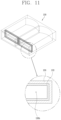
FIG. 7 is a schematic view illustrating another example of the insulating part 130 in FIG. 6 ; FIG. 8 is a schematic view illustrating another example of the insulating part 130 in FIG. 6 ; FIG. 9 is a schematic view illustrating another example of the insulating part 130 in FIG. 6 ; FIG. 10 is a schematic view illustrating another example of the insulating part 130 in FIG. 6 ; and FIG. 11 is a schematic view illustrating another example of the insulating part 130 in FIG. 6 , viewed from the bottom.
Referring to FIG. 7 , the insulating part 130 may further include an adhesive layer 134.
As illustrated in FIG. 7 , the adhesive layer 134 is provided on an inner surface of the insulating part 130. The adhesive layer 134 may be implemented as an adhesive. While the insulating part 130 is inserted into the joint portions 120 a of the stator coils 120, the adhesive layer 134 may be adhered and fixed to contacted or touched joint portions 120 a, the first and second conductors 121 a and 121 b, and the covering portions 122. Accordingly, when the insulating part 130 is insertedly coupled to the joint portions 120 a, the insulating part 130 may be securely coupled to the joint portions 120 a. The adhesive layer 134 may be provided in the form of a liquid or solid such as powder.
Next, referring to FIG. 8 , the insulating part 130 may include a first insulating portion 130′ and a second insulating portion 130″ made of different types of dielectric materials. Here, the first insulating portion 130′ may define any one portion of the insulating part 130, and the second insulating portion 130″ may define another portion of the insulating part 130. The first and second insulating portions 130′ and 130″ may allow the insulating part 130 to have more various insulation properties, compared to the insulating part 130 made of one kind of the dielectric material.
Meanwhile, the first insulating portion 130′ may define an inner side of the insulating part 130 and have a first elastic force. The second insulating portion 130″ may define an outer side of the insulating part 130 and have a second elastic force which is less than the first elastic force.
By doing so, when some ends of the stator coils 120, which define the joint portions 120 a, have different bending degrees, or when some of the joint portions 120 a have different shapes, ends of the stator coils 120 or the first insulating portions 130′ in contact with the joint portions 120 a are elastically deformed. This allows the insulating part 130 to be coupled to the joint portions 120 a in an easier manner without being stuck or caught. In addition, while the second insulating portion 130″ has an elastic force less than the first insulating portion 130′, it protects ends of the stator coils 120 and/or joint portions 120 a provided inside the insulating part 130 from external impact, or the like, thereby preventing damage to them.
Referring to FIGS. 9 and 11 , the insulating part 130 may further include a support portion 133.
The support portion 133 may protrude from the inner surface of the insulating part 130, and configured to be elastically deformable. Meanwhile, the support portion 133 may be provided in plurality. In addition, the support portion 133 may have a hemisphere shape. The plurality of support portions 133 may be provided on the inner surface of the insulating part 130 to be spaced apart from one another at a predetermined interval.
Alternatively, as shown in FIG. 11 , the support portion 133 may extend on the inner surface of the insulating part 130 along a perimeter of the insulating part 130.
In addition, as illustrated in FIG. 9 , while the insulating part 130 is inserted into each of the joint portions 120 a of the stator coils 120, the support portion 133 may be disposed at a position that faces the covering portion 122 and pressed by the covering portion 122 to be supported thereon.
Alternatively, as shown in FIG. 10 , while the insulating part 130 is inserted into each of the joint portions 120 a of the stator coils 120, the support portion 133 may be disposed at a position that faces at least one of the first and second conductors 121 a and 121 b, and pressed by the at least one of the first and second conductors 121 a and 121 b to be supported thereon. The support portion 133 may be provided in plurality. In addition, the plurality of support portions 133 may be disposed at different heights of the insulating part 130. The plurality of support portions 133 may have different sizes.
The support portion 133 may allow the insulating part 120 to be more securely coupled to the joint portions 120 a while being inserted into the joint portions 120 a of the stator coils 120. Accordingly, even when impact or shock is applied to the stator 100, or vibration occurs, the insulating part 130 and the joint portions 120 a may be securely coupled to each other.
Hereinafter, a method of manufacturing the stator 100 of FIGS. 1A and 1B will be described with reference to FIG. 12 in addition to FIGS. 1A to 11 .
FIG. 12 is a flowchart illustrating a method of manufacturing the stator 100 illustrated in FIGS. 1A and 1B.
Referring to FIG. 12 , a method for manufacturing the stator 100 includes welding two ends of each of the stator coils 120 to form one joint portion 120 a (S100), inserting the insulating part 130 into the joint portions 120 a (S200), impregnating a coating material into the stator coils 120 (S300), and curing the coating material impregnated into the stator coils 120 (S400).
More specifically, the method of manufacturing the stator 100 is as follows. First, two ends of each of the stator coils 120 wound on the stator core 110 of the stator 100 are welded together to form one joint portion 120 a. Here, each of the stator coils 120 may be formed in a U shape to be wound around the stator core 110. In addition, the two ends of each of the stator coils 120 may be made of bare copper that is uncoated.
Next, the insulating part 130 made of a dielectric material, formed as a single body, and provided with a plurality of openings 130 a is inserted into the joint portions 120 a of the stator coils 120 through the openings 130 a to be fixed.
Subsequently, while the insulating part 130 is coupled to the joint portions 120 a of the stator coils 120, a coating material is impregnated into the stator coils 120 to form a film thereon. Here, the coating material may be varnish. The coating material may be impregnated not only into the stator coils 120, but also into an outer surface of the insulating part 130 coupled to the joint portions 120 a of the stator coils 120.
Next, the coating material impregnated into the stator coils 120 is cured.
In the manufacturing process of the stator core 100, an epoxy coating (or application) step performed for insulating the joint portions 120 a of the stator coils 120, which is included in the conventional stator manufacturing process is not required. As a result, a time required for the manufacturing process of the stator 100 may be greatly reduced.
For reference, the epoxy coating step included in the manufacturing process of the related art stator may be performed on the joint portions 120 a of the stator coils 120 after the step S100 of welding two ends of each of the stator coils 120 to form one joint portion 120 a, the step S300 of impregnating the coating material into the stator coils 120, and the step S400 of curing the coating material impregnated into the stator coils 120.
According to the embodiments disclosed herein, a stator includes stator coils, each having two ends electrically connected to form one joint portion and an insulating part inserted into each of the joint portions through a plurality of openings provided at one side thereof to cover at least respective parts of the joint portions, so as to allow a distance between neighboring joint portions to be maintained. Here, the insulating part is made of a dielectric material, has a plurality of accommodation spaces partitioned from one another, and formed as a single body.
A predetermined distance between the neighboring joint portions of the stator coils may be securely maintained by coupling the insulating part having the plurality of partitioned accommodation spaces to the plurality of joint portions of the stator coils through the openings. As a result, a partial discharge caused by a surge between the joint portions of the stator coils may be prevented, allowing operational reliability of the stator to be increased. Further, as the insulating part is formed as the single body, an assembly process of coupling the insulating part to the joint portions of the stator coils may be performed in an easier manner.
Owing to the insulating part made of the dielectric material and inserted into and coupled to the joint portions of the stator coils, an epoxy coating step performed for insulating the joint portions of the stator coils, which is included in the conventional stator manufacturing process, may not be required. Further, insulation area (or region) may be formed more evenly or uniformly compared to the conventional insulation method of epoxy coating on the joint portions of the stator coils. As a result, insulation performance required for the joint portions of the stator coils may be improved.

Claims (17)

What is claimed is:
1. A stator, comprising:
a stator core having a plurality of slots;
a plurality of stator coils inserted into the plurality of slots and wound on the stator core, each of the plurality of stator coils having two ends electrically connected to form a joint portion; and
an insulating part made of a dielectric material, formed as a single body, having a plurality of openings, joint portions of the plurality of stator coils being inserted into the insulating part through the openings, the insulating part being configured to cover at least respective parts of the joint portions and provide a distance between neighboring joint portions,
wherein each of the plurality of stator coils comprises:
a first conductor and a second conductor configured to allow electric current to flow therethrough, the first conductor and the second conductor defining the two ends of the stator coil, respectively; and
covering portions configured to cover respective parts of the first and second conductors, excluding the joint portion, and provide protection,
wherein the insulating part partially covers the covering portions, and
wherein the insulating part further comprises a support portion protruding from an inner surface thereof, the support portion being configured to be elastically deformable.
2. The stator of claim 1, wherein the plurality of openings are disposed on a first side of the insulating part, and
wherein a second side disposed opposite the first side is closed.
3. The stator of claim 1, wherein the support portion is disposed on a portion of the insulating part facing the covering portion, and the support portion is disposed between the insulating portion and the covering portion.
4. The stator of claim 1, wherein the support portion is disposed on a portion of the insulating part facing at least one of the first and second conductors, and the support portion is disposed between the insulating portion and at least one of the first and second conductors.
5. The stator of claim 1, wherein the support portion has a hemispherical shape.
6. The stator of claim 1, wherein the support portion extends on an inner surface of the insulating part along a perimeter of the insulating part.
7. The stator of claim 1, wherein the insulating part further includes a plurality of accommodation spaces partitioned from each other and inserted into each of the joint portions, and
wherein each of the accommodation spaces has a first inner diameter defining an area that surrounds the joint portion and a second inner diameter defining an area that surrounds the covering portions, so that the insulating part is engagingly supported by the covering portions when inserted into the joint portion.
8. The stator of claim 1, wherein the insulating part includes a first insulating portion and a second insulating portion made of different types of dielectric materials.
9. The stator of claim 8, wherein the first insulating portion defines an inner side of the insulating part and has a first Young's modulus, and
wherein the second insulating portion defines an outer side of the insulating part and has a second Young's modulus higher than the first Young's modulus.
10. The stator of claim 1, wherein the insulating part further includes an adhesive layer provided on an inner surface thereof.
11. The stator of claim 1, wherein the insulating part comprises:
a first portion defining an upper surface thereof; and
a second portion defining a side surface thereof,
wherein a thickness of the first portion is less than a thickness of the second portion.
12. The stator of claim 1, wherein the dialectic material has a dielectric constant ranging between 3 and 5.
13. The stator of claim 12, wherein the dielectric material includes at least one of Polyimide (PI), Polyamideimide (PAI), and Polyetheretherketone (PEEK).
14. The stator of claim 1, wherein the plurality of stator coils is spaced apart from one another along a circumference of the stator core by a predetermined interval, and
wherein the insulating part has a ring shape to cover the joint portions of the plurality of stator coils.
15. A method of manufacturing the stator of claim 1, the method comprising:
welding two ends of each of the plurality of stator coils wound on the stator core to form the joint portion;
inserting joint portions of the plurality of stator coils into the plurality of openings in the insulating part made of the dielectric material;
impregnating a coating material into the plurality of stator coils to form a film thereon; and
curing the impregnated coating material.
16. The method of claim 15, wherein the coating material includes varnish.
17. The method of claim 15, wherein the dielectric material has a dielectric constant ranging between 3 and 5.
US17/039,860 2020-03-17 2020-09-30 Stator and method for manufacturing the same Active 2041-07-30 US11652375B2 (en)

Applications Claiming Priority (2)

Application Number Priority Date Filing Date Title
KR1020200032811A KR102744079B1 (en) 2020-03-17 2020-03-17 Stator
KR10-2020-0032811 2020-03-17

Publications (2)

Publication Number Publication Date
US20210296947A1 US20210296947A1 (en) 2021-09-23
US11652375B2 true US11652375B2 (en) 2023-05-16

Family

ID=73343924

Family Applications (1)

Application Number Title Priority Date Filing Date
US17/039,860 Active 2041-07-30 US11652375B2 (en) 2020-03-17 2020-09-30 Stator and method for manufacturing the same

Country Status (4)

Country Link
US (1) US11652375B2 (en)
EP (1) EP3883097B1 (en)
KR (1) KR102744079B1 (en)
CN (1) CN113410925B (en)

Cited By (1)

* Cited by examiner, † Cited by third party
Publication number Priority date Publication date Assignee Title
US20240333062A1 (en) * 2023-03-29 2024-10-03 Aichi Electric Co., Ltd. Motor

Families Citing this family (2)

* Cited by examiner, † Cited by third party
Publication number Priority date Publication date Assignee Title
JP2025014192A (en) * 2023-07-18 2025-01-30 トヨタ自動車株式会社 Stator
WO2025192435A1 (en) * 2024-03-11 2025-09-18 日本発條株式会社 Connecting structure, and stator for rotary electric machine employing same

Citations (5)

* Cited by examiner, † Cited by third party
Publication number Priority date Publication date Assignee Title
JP2000209802A (en) 1999-01-18 2000-07-28 Denso Corp INSULATING STRUCTURE OF JOINT, INSULATING STRUCTURE OF ROTARY ELECTRIC MACHINE
US20120274156A1 (en) * 2011-04-29 2012-11-01 Chamberlin Bradley D Electric machine module insulation system and method
JP2013115832A (en) 2011-11-24 2013-06-10 Toyota Motor Corp Motor
JP2014023210A (en) 2012-07-13 2014-02-03 Toyota Motor Corp Motor
WO2020120626A1 (en) 2018-12-12 2020-06-18 Thyssenkrupp Ag Isolating ring, stator and electric machine

Family Cites Families (7)

* Cited by examiner, † Cited by third party
Publication number Priority date Publication date Assignee Title
JP5240131B2 (en) * 2009-09-02 2013-07-17 トヨタ自動車株式会社 Motor cooling structure
JP6118594B2 (en) * 2013-03-15 2017-04-19 日立オートモティブシステムズ株式会社 Coil, rotating electric machine including the same, and manufacturing method thereof
JP2014187763A (en) * 2013-03-22 2014-10-02 Toyota Motor Corp Stator
JP2016127629A (en) * 2014-12-26 2016-07-11 トヨタ自動車株式会社 Stator for rotating electrical machine and manufacturing method thereof
US10587157B2 (en) * 2015-07-06 2020-03-10 Aisin Aw Co., Ltd. Stator for rotating electrical machine
EP3544159B1 (en) * 2016-11-18 2023-08-16 Hitachi Astemo, Ltd. Method for manufacturing rotary electric machine
JPWO2019220635A1 (en) * 2018-05-18 2020-05-28 三菱電機株式会社 Stator, rotating electric machine and stator manufacturing method

Patent Citations (5)

* Cited by examiner, † Cited by third party
Publication number Priority date Publication date Assignee Title
JP2000209802A (en) 1999-01-18 2000-07-28 Denso Corp INSULATING STRUCTURE OF JOINT, INSULATING STRUCTURE OF ROTARY ELECTRIC MACHINE
US20120274156A1 (en) * 2011-04-29 2012-11-01 Chamberlin Bradley D Electric machine module insulation system and method
JP2013115832A (en) 2011-11-24 2013-06-10 Toyota Motor Corp Motor
JP2014023210A (en) 2012-07-13 2014-02-03 Toyota Motor Corp Motor
WO2020120626A1 (en) 2018-12-12 2020-06-18 Thyssenkrupp Ag Isolating ring, stator and electric machine

Non-Patent Citations (2)

* Cited by examiner, † Cited by third party
Title
European Search Report for European Patent Application No. 20206949.8 dated Apr. 16, 2021 (10 pages).
Machine translation of JP 2000209802 A retrieved from internal search (Year: 2000). *

Cited By (1)

* Cited by examiner, † Cited by third party
Publication number Priority date Publication date Assignee Title
US20240333062A1 (en) * 2023-03-29 2024-10-03 Aichi Electric Co., Ltd. Motor

Also Published As

Publication number Publication date
CN113410925A (en) 2021-09-17
US20210296947A1 (en) 2021-09-23
EP3883097A1 (en) 2021-09-22
KR102744079B1 (en) 2024-12-19
CN113410925B (en) 2024-04-23
KR20210116091A (en) 2021-09-27
EP3883097B1 (en) 2022-12-28

Similar Documents

Publication Publication Date Title
US7948130B2 (en) Rotating electrical machine
US11652375B2 (en) Stator and method for manufacturing the same
CN105322682B (en) Stator for rotating electric machine
JP7004766B2 (en) Compressor drive with insulation
US20150022045A1 (en) Electrical Rotating Machine
CN103503280A (en) Electric machine module insulation system and method
US11658535B2 (en) Apparatus for driving a compressor and method for assembling the apparatus
KR20120104281A (en) Rotating electrical machine and method for manufacturing same
EP1267472B1 (en) Electrical isolation layer for generator stator strand assembly and other uses
US20240128824A1 (en) Dynamo-Electric Machine
US11984782B2 (en) Stator coil and stator comprising said stator coil, rotating electrical machine, and manufacturing method for stator coil
US20200083771A1 (en) Electric wire segment and stator
KR102741456B1 (en) Stator
US11418082B2 (en) Stator used for motor and method for manufacturing said stator
JP7474932B2 (en) Molded Motor
CN109391053B9 (en) Stator for rotating electric machine
WO2022004299A1 (en) Coil, motor, and manufacturing method
US11973386B2 (en) Rotary electric machine and method of manufacturing rotary electric machine
CN115603479A (en) Rotating electrical machines and stators of rotating electrical machines
JPWO2022004299A5 (en)
JP3183655B2 (en) Rotating electric machine and method of manufacturing the same
CN114365395A (en) Stator and method for manufacturing stator
CN110932420A (en) Stator and method for manufacturing stator
JP7067344B2 (en) Armature
JP2019097306A (en) Formation method for stator coil of rotary electric machine

Legal Events

Date Code Title Description
FEPP Fee payment procedure

Free format text: ENTITY STATUS SET TO UNDISCOUNTED (ORIGINAL EVENT CODE: BIG.); ENTITY STATUS OF PATENT OWNER: LARGE ENTITY

AS Assignment

Owner name: LG ELECTRONICS INC., KOREA, REPUBLIC OF

Free format text: ASSIGNMENT OF ASSIGNORS INTEREST;ASSIGNORS:SHIN, HOJUN;SUNG, WONJUNG;PARK, GYEONGJAE;AND OTHERS;REEL/FRAME:053942/0839

Effective date: 20200923

STPP Information on status: patent application and granting procedure in general

Free format text: DOCKETED NEW CASE - READY FOR EXAMINATION

AS Assignment

Owner name: LG MAGNA E-POWERTRAIN CO., LTD., KOREA, REPUBLIC OF

Free format text: ASSIGNMENT OF ASSIGNORS INTEREST;ASSIGNOR:LG ELECTRONICS INC.;REEL/FRAME:057314/0976

Effective date: 20210726

STPP Information on status: patent application and granting procedure in general

Free format text: NON FINAL ACTION MAILED

STPP Information on status: patent application and granting procedure in general

Free format text: RESPONSE TO NON-FINAL OFFICE ACTION ENTERED AND FORWARDED TO EXAMINER

STCF Information on status: patent grant

Free format text: PATENTED CASE