US11652262B2 - Battery module, battery pack, and device - Google Patents
Battery module, battery pack, and device Download PDFInfo
- Publication number
- US11652262B2 US11652262B2 US17/535,189 US202117535189A US11652262B2 US 11652262 B2 US11652262 B2 US 11652262B2 US 202117535189 A US202117535189 A US 202117535189A US 11652262 B2 US11652262 B2 US 11652262B2
- Authority
- US
- United States
- Prior art keywords
- bulge
- electrode terminal
- battery module
- connecting plate
- insulation board
- Prior art date
- Legal status (The legal status is an assumption and is not a legal conclusion. Google has not performed a legal analysis and makes no representation as to the accuracy of the status listed.)
- Active
Links
Images


Classifications
-
- H—ELECTRICITY
- H01—ELECTRIC ELEMENTS
- H01M—PROCESSES OR MEANS, e.g. BATTERIES, FOR THE DIRECT CONVERSION OF CHEMICAL ENERGY INTO ELECTRICAL ENERGY
- H01M50/00—Constructional details or processes of manufacture of the non-active parts of electrochemical cells other than fuel cells, e.g. hybrid cells
- H01M50/50—Current conducting connections for cells or batteries
- H01M50/572—Means for preventing undesired use or discharge
-
- H—ELECTRICITY
- H01—ELECTRIC ELEMENTS
- H01M—PROCESSES OR MEANS, e.g. BATTERIES, FOR THE DIRECT CONVERSION OF CHEMICAL ENERGY INTO ELECTRICAL ENERGY
- H01M50/00—Constructional details or processes of manufacture of the non-active parts of electrochemical cells other than fuel cells, e.g. hybrid cells
- H01M50/20—Mountings; Secondary casings or frames; Racks, modules or packs; Suspension devices; Shock absorbers; Transport or carrying devices; Holders
- H01M50/204—Racks, modules or packs for multiple batteries or multiple cells
- H01M50/207—Racks, modules or packs for multiple batteries or multiple cells characterised by their shape
- H01M50/209—Racks, modules or packs for multiple batteries or multiple cells characterised by their shape adapted for prismatic or rectangular cells
-
- H—ELECTRICITY
- H01—ELECTRIC ELEMENTS
- H01M—PROCESSES OR MEANS, e.g. BATTERIES, FOR THE DIRECT CONVERSION OF CHEMICAL ENERGY INTO ELECTRICAL ENERGY
- H01M50/00—Constructional details or processes of manufacture of the non-active parts of electrochemical cells other than fuel cells, e.g. hybrid cells
- H01M50/20—Mountings; Secondary casings or frames; Racks, modules or packs; Suspension devices; Shock absorbers; Transport or carrying devices; Holders
- H01M50/233—Mountings; Secondary casings or frames; Racks, modules or packs; Suspension devices; Shock absorbers; Transport or carrying devices; Holders characterised by physical properties of casings or racks, e.g. dimensions
- H01M50/24—Mountings; Secondary casings or frames; Racks, modules or packs; Suspension devices; Shock absorbers; Transport or carrying devices; Holders characterised by physical properties of casings or racks, e.g. dimensions adapted for protecting batteries from their environment, e.g. from corrosion
-
- H—ELECTRICITY
- H01—ELECTRIC ELEMENTS
- H01M—PROCESSES OR MEANS, e.g. BATTERIES, FOR THE DIRECT CONVERSION OF CHEMICAL ENERGY INTO ELECTRICAL ENERGY
- H01M50/00—Constructional details or processes of manufacture of the non-active parts of electrochemical cells other than fuel cells, e.g. hybrid cells
- H01M50/20—Mountings; Secondary casings or frames; Racks, modules or packs; Suspension devices; Shock absorbers; Transport or carrying devices; Holders
- H01M50/249—Mountings; Secondary casings or frames; Racks, modules or packs; Suspension devices; Shock absorbers; Transport or carrying devices; Holders specially adapted for aircraft or vehicles, e.g. cars or trains
-
- H—ELECTRICITY
- H01—ELECTRIC ELEMENTS
- H01M—PROCESSES OR MEANS, e.g. BATTERIES, FOR THE DIRECT CONVERSION OF CHEMICAL ENERGY INTO ELECTRICAL ENERGY
- H01M50/00—Constructional details or processes of manufacture of the non-active parts of electrochemical cells other than fuel cells, e.g. hybrid cells
- H01M50/20—Mountings; Secondary casings or frames; Racks, modules or packs; Suspension devices; Shock absorbers; Transport or carrying devices; Holders
- H01M50/271—Lids or covers for the racks or secondary casings
-
- H—ELECTRICITY
- H01—ELECTRIC ELEMENTS
- H01M—PROCESSES OR MEANS, e.g. BATTERIES, FOR THE DIRECT CONVERSION OF CHEMICAL ENERGY INTO ELECTRICAL ENERGY
- H01M50/00—Constructional details or processes of manufacture of the non-active parts of electrochemical cells other than fuel cells, e.g. hybrid cells
- H01M50/50—Current conducting connections for cells or batteries
- H01M50/502—Interconnectors for connecting terminals of adjacent batteries; Interconnectors for connecting cells outside a battery casing
- H01M50/507—Interconnectors for connecting terminals of adjacent batteries; Interconnectors for connecting cells outside a battery casing comprising an arrangement of two or more busbars within a container structure, e.g. busbar modules
-
- H—ELECTRICITY
- H01—ELECTRIC ELEMENTS
- H01M—PROCESSES OR MEANS, e.g. BATTERIES, FOR THE DIRECT CONVERSION OF CHEMICAL ENERGY INTO ELECTRICAL ENERGY
- H01M50/00—Constructional details or processes of manufacture of the non-active parts of electrochemical cells other than fuel cells, e.g. hybrid cells
- H01M50/50—Current conducting connections for cells or batteries
- H01M50/543—Terminals
- H01M50/552—Terminals characterised by their shape
-
- H—ELECTRICITY
- H01—ELECTRIC ELEMENTS
- H01M—PROCESSES OR MEANS, e.g. BATTERIES, FOR THE DIRECT CONVERSION OF CHEMICAL ENERGY INTO ELECTRICAL ENERGY
- H01M50/00—Constructional details or processes of manufacture of the non-active parts of electrochemical cells other than fuel cells, e.g. hybrid cells
- H01M50/50—Current conducting connections for cells or batteries
- H01M50/572—Means for preventing undesired use or discharge
- H01M50/584—Means for preventing undesired use or discharge for preventing incorrect connections inside or outside the batteries
- H01M50/59—Means for preventing undesired use or discharge for preventing incorrect connections inside or outside the batteries characterised by the protection means
- H01M50/591—Covers
-
- H—ELECTRICITY
- H01—ELECTRIC ELEMENTS
- H01M—PROCESSES OR MEANS, e.g. BATTERIES, FOR THE DIRECT CONVERSION OF CHEMICAL ENERGY INTO ELECTRICAL ENERGY
- H01M2220/00—Batteries for particular applications
- H01M2220/20—Batteries in motive systems, e.g. vehicle, ship, plane
-
- Y—GENERAL TAGGING OF NEW TECHNOLOGICAL DEVELOPMENTS; GENERAL TAGGING OF CROSS-SECTIONAL TECHNOLOGIES SPANNING OVER SEVERAL SECTIONS OF THE IPC; TECHNICAL SUBJECTS COVERED BY FORMER USPC CROSS-REFERENCE ART COLLECTIONS [XRACs] AND DIGESTS
- Y02—TECHNOLOGIES OR APPLICATIONS FOR MITIGATION OR ADAPTATION AGAINST CLIMATE CHANGE
- Y02E—REDUCTION OF GREENHOUSE GAS [GHG] EMISSIONS, RELATED TO ENERGY GENERATION, TRANSMISSION OR DISTRIBUTION
- Y02E60/00—Enabling technologies; Technologies with a potential or indirect contribution to GHG emissions mitigation
- Y02E60/10—Energy storage using batteries
Definitions
- This application relates to the technical field of energy storage devices, and in particular, to a battery module, a battery pack, and a device.
- a battery module includes a plurality of battery cells, and a battery cell includes electrode terminals. Different electrode terminals are connected by connecting plates, so that the plurality of battery cells are connected. Generally, a connecting plate is connected to an electrode terminal by welding. Metal particles generated during the welding are scattered between the battery cells, and are very difficult to clean up. In addition, the metal particles are likely to cause a short circuit between adjacent battery cells and bring hazards.
- the battery module reduces a probability for metal particles and other impurities to enter regions between battery cells, reduces difficulty of cleaning the battery module, and improves safety and reliability of the battery pack.
- This application provides a battery module, including:
- the insulation board according to this application can not only shield each battery cell, but also cover a part of the electrode terminal by using the first bulge, thereby reducing a risk of letting metal particles enter a position between the battery cells, reducing difficulty of cleaning the battery module, and improving safety and reliability of the battery module.
- a via hole is disposed on the top wall.
- the via hole runs through to the accommodation cavity. A part of the electrode terminal is exposed out of the via hole.
- the electrode terminal includes a base portion and a first connecting portion protruding from the base portion.
- the top wall covers at least a part of the base portion.
- the first connecting portion is exposed out of the via hole.
- a top surface of the first connecting portion is not lower than a top surface of the top wall.
- the battery module further includes a connecting plate.
- the connecting plate is located on a side of the insulation board away from the battery cell.
- the connecting plate is configured to connect the part of the electrode terminal, the part being exposed out of the via hole.
- the connecting plate covers the via hole.
- an accommodation slot is disposed on the body portion.
- the first bulge is disposed on a bottom wall of the accommodation slot.
- a plurality of second bulges connected to the bottom wall are disposed on the body portion.
- Each second bulge is located on an outer rim of the first bulge.
- a protrusion direction of the second bulge is identical to that of the first bulge.
- the insulation board includes a flange.
- the flange is disposed on an outer rim of the body portion.
- An extension direction of the flange is identical to the protrusion direction of the first bulge.
- a second aspect of this application provides a battery pack.
- the battery pack includes a box body and the battery module described above.
- the battery module is accommodated in the box body.
- a third aspect of this application provides a device, including:
- a first bulge is disposed on the insulation board.
- the first bulge may include a sidewall and a top wall that define an accommodation cavity.
- the insulation board according to this application can not only shield each battery cell, but also cover a part of the electrode terminal by using the first bulge, thereby reducing the risk of letting metal particles enter a position between the battery cells, reducing difficulty of cleaning the battery module, and improving safety and reliability of the battery module.
- FIG. 1 is a schematic structural diagram of a device according to an embodiment of this application.
- FIG. 2 is a schematic structural diagram of a battery pack according to an embodiment of this application.
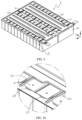
- FIG. 3 is a schematic structural diagram of an insulation board and a battery cell array according to an embodiment of this application;
- FIG. 4 is a local detailed view of a position I shown in FIG. 3 ;
- FIG. 5 is a schematic structural diagram of an insulation board mounted in a battery cell array according to an embodiment of this application.
- FIG. 6 is a local detailed view of a position II shown in FIG. 5 ;
- FIG. 7 is a schematic structural diagram of a battery cell array according to an embodiment of this application.
- FIG. 8 is a local detailed view of a position III shown in FIG. 7 ;
- FIG. 9 is a schematic structural diagram of a battery module according to an embodiment of this application.
- FIG. 10 is a local detailed view of a position IV shown in FIG. 9 ;
- FIG. 11 is a schematic structural diagram of a connecting piece according to an embodiment of this application.
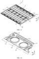
- FIG. 12 is a top view of an insulation board according to an embodiment of this application.
- FIG. 13 is a schematic structural diagram of an insulation board according to an embodiment of this application.
- FIG. 14 is a local detailed view of a position V shown in FIG. 13 ;
- FIG. 15 is a local detailed view of a position VI shown in FIG. 13 ;
- FIG. 16 is a local detailed view of a position VII shown in FIG. 13 .
- a 1 Battery cell array
- the term “and/or” used herein only describes an association relationship between associated objects and indicates existence of three relationships.
- “A and/or B” may indicate existence of A alone, coexistence of A and B, and existence of B alone.
- the character “/” herein generally indicates an “or” relationship between the object preceding the character and the object following the character.
- connection may be a fixed connection, or a detachable connection, or an integrated connection, or an electrical connection; and may be a direct connection or an indirect connection implemented through an intermediate medium.
- An embodiment of this application provides a device that uses a battery cell as a power supply, a battery pack, and a battery module.
- the device that uses a battery cell as a power supply may be a vehicle, a ship, a small aircraft, an energy storage cabinet, or the like.
- the device may contain a power source, and the power source is used to provide a driving force for the device.
- the power source may be configured as a battery module or pack that provides electrical energy to the device.
- the driving force of the device may be sole electrical energy, or may include electrical energy and other types of energy (such as mechanical energy).
- the power source may be a battery module (or a battery pack), or may be a combination of a battery module (or battery pack) and an engine, or the like. Therefore, all devices that can use a battery cell as a power supply fall within the protection scope of this application.
- a vehicle may be a new energy vehicle.
- the new energy vehicle may be a battery electric vehicle, or may be a hybrid electric vehicle, a range-extended electric vehicle, or the like.
- the vehicle may include a battery pack M and a vehicle body.
- the battery pack M is disposed in the vehicle body.
- a driving motor is further disposed in the vehicle body, and the driving motor is electrically connected to the battery pack M.
- the battery pack M provides electrical energy.
- the driving motor is connected to wheels of the vehicle body through a transmission mechanism to drive the vehicle to run.
- the battery pack M may be horizontally disposed at a bottom of the vehicle body.
- the battery pack M includes a box body M 1 and a battery module A.
- the box body M 1 contains a cavity M 2 .
- the battery module A is accommodated in the cavity M 2 .
- the battery module A may be one or more in number.
- a plurality of battery modules A are arranged in the accommodation cavity.
- the box body M 1 is not limited in terms of type, and may be a frame shape, a disk shape, or a box shape. Specifically, as shown in FIG. 2 , the box body M 1 may contain a lower box that accommodates the battery module A and an upper box that fits the lower box.
- the battery module A includes a plurality of battery cells 1 .
- the plurality of battery cells 1 are stacked alongside each other in a length direction X to form a battery cell array A 1 .
- Each battery cell 1 includes electrode terminals 11 .
- the electrode terminals 11 are configured to output electrical energy.
- Each battery cell 1 includes a positive electrode terminal and a negative electrode terminal.
- the plurality of battery cells 1 are electrically connected, and specifically, may be connected in series and/or parallel or the like.
- the battery cells 1 are connected to each other by a connecting plate 3 .
- a positive electrode terminal of one battery cell 1 is connected to a negative electrode terminal of another battery cell 1 by the connecting plate 3 .
- the connecting plate 3 is welded to the positive electrode terminal and the negative electrode terminal.
- Metal particles are generated during the welding.
- the metal particles are scattered throughout the battery module A, for example, scattered between different battery cells 1 and between the electrode terminal 11 and the connecting plate 3 . Consequently, through the metal particles, a short circuit may occur between adjacent battery cells 1 , and between the electrode terminal 11 and the connecting plate 3 , thereby affecting the charge and discharge process of the battery module A. Therefore, after the connecting plate 3 is welded to the electrode terminal 11 , the battery module A needs to be cleaned to remove the metal particles in the battery module A to improve the safety and reliability of the battery module A.
- the battery module A may be cleaned by performing steps such as turning over, adsorbing, and cleaning, so as to remove the metal particles in the battery module A.
- steps such as turning over, adsorbing, and cleaning, so as to remove the metal particles in the battery module A.
- the cleaning can be performed for the battery pack M as a whole, and adsorption cleaning can hardly be performed for the battery pack M, resulting in a risk of leaving residual metal particles in the battery pack M.
- the conventional battery module A may further include an insulation board.
- the insulation board lies as a covering above the electrode terminal 11 of each battery cell 1 .
- the connecting plate 3 is located above the insulation board.
- a via hole configured to pass the electrode terminal 11 is disposed on the insulation board. A relatively large gap exists between the via hole and the electrode terminal 11 so that the electrode terminal 11 that passes through the via hole can be welded to the connecting plate 3 .
- the via hole of the insulation board is also a place where the metal particles are likely to be scattered, and is difficult to clean up.
- the battery module A may include at least one battery cell 1 and an insulation board 2 .
- the battery cells 1 are stacked alongside each other in the length direction X to form a battery cell array A 1 .
- Each battery cell 1 includes electrode terminals 11 .
- the insulation board 2 is disposed on the top of the battery cell 1 .
- the insulation board 2 may include a body portion 21 .
- a first bulge 22 exists on and protrudes from the body portion 21 .
- the first bulge 22 may include a sidewall 221 and a top wall 222 .
- the top wall 222 is connected to the body portion 21 through the sidewall 221 , and the top wall and sidewall define an accommodation cavity.
- the insulation board 2 is connected to the battery cell array A 1 , at least a part of the electrode terminal 11 is located in the accommodation cavity.
- the top wall 222 of the first bulge 22 covers a part of the electrode terminal 11 .
- the insulation board 2 disposed on the top of the battery cell 1 can shield each battery cell 1 , reduce the risk of letting the metal particles and other impurities enter a position between the battery cells 1 , and reduce the difficulty of cleaning the battery module A.
- the insulation board 2 can insulate each battery cell 1 from other metal parts, thereby improving reliability of the battery cell 1 .
- the insulation board 2 covers a part of the electrode terminal 11 through the first bulge 22 , thereby reducing the risk of letting the metal particles and other impurities enter the regions between adjacent battery cells 1 through the insulation board 2 .
- the metal particles when the metal particles fall on the first bulge 22 , the metal particles can slide down onto the insulation board 2 through the sidewall 221 of the first bulge 22 , thereby further reducing the risk of letting the metal particles enter the battery module A. In this way, the metal particles and other impurities just attach to the surface of the insulation board 2 . In cleaning the battery module A after completion of the welding, it is necessary to clean just the surface of the insulation board 2 away from the battery cell 1 , but not necessary to clean the positions between the battery cells 1 , thereby reducing difficulty of cleaning the battery module A and improving the safety and reliability of the battery module A.
- a via hole 222 a may be disposed on the top wall 222 of the first bulge 22 .
- the via hole 222 a runs through the top wall 222 and communicates to the accommodation cavity.
- a part of the electrode terminal 11 can extend out along the via hole 222 a. That is, a part of the electrode terminal 11 is exposed out of the via hole 222 a.
- This part of the electrode terminal 11 may be configured to connect to the connecting plate 3 , for example, by welding, so as to implement electrical connection of the battery cell 1 .
- the electrode terminal 11 when a part of the electrode terminal 11 extends out along the via hole 222 a of the first bulge 22 , the electrode terminal 11 can be welded to the connecting plate 3 . Moreover, before the welding, the part of the electrode terminal 11 , which extends out of the via hole 222 a, can be located by means of the via hole 222 a to increase accuracy of connection of the connecting plate 3 , thereby improving the stability of the connection between the connecting plate 3 and the electrode terminal 11 .
- the sidewall of the part of the electrode terminal 11 may abut against the sidewall of the via hole 222 a. That is, there is no gap or just a small gap between the electrode terminal 11 and the sidewall of the via hole 222 a, thereby further reducing the risk of letting the metal particles or other impurities fall into the battery module A.
- the electrode terminal 11 may include a base portion 111 and a first connecting portion 112 .
- the first connecting portion 112 protrudes against the base portion 111 .
- the first connecting portion 112 can extend out along the via hole 222 a.
- the top wall 222 of the first bulge 22 covers at least a part of the base portion 111 .
- the insulation board 2 when the insulation board 2 is connected to the battery cell array A 1 , because the first connecting portion 112 of the electrode terminal 11 extends out of the corresponding via hole 222 a, the insulation board 2 and the battery cell array A 1 can be located through each base portion 111 and the sidewall of the via hole 222 a, thereby improving the accuracy of the positions of and reliability of connection between the insulation board 2 and the battery cell array A 1 .
- the gap between the electrode terminal 11 and the via hole 222 a of the insulation board 2 is further reduced, thereby reducing the risk of letting the metal particles or other impurities enter the accommodation cavity and reducing the risk of letting the metal particles or other impurities enter the battery module A.
- a top surface of the first connecting portion 112 is not lower than a top surface of the top wall 222 . That is, the first connecting portion 112 is flush with or protruding against the top wall 222 .
- Such a design facilitates the electrode terminal 11 to connect to the connecting plate 3 through the first connecting portion 112 , and also facilitates the locating of the connecting plate 3 and the electrode terminal 11 at the time of connecting with the connecting plate 3 .
- the connecting plate 3 is situated on a side of the insulation board 2 away from the battery cell 1 , and is connected to a part of the electrode terminal 11 , the part being exposed out of the via hole 222 a. This facilitates the welding between the connecting plate 3 and the electrode terminal 11 .
- the welding position between the connecting plate 3 and the electrode terminal 11 is on a side of the insulation board 2 away from the battery cell 1 . Therefore, the risk of letting the metal particles generated during welding fall into the position between the battery cells 1 is further reduced, and the safety and reliability of the battery module A are improved.
- the connecting plate 3 can cover the via hole 222 a.
- the connecting plate 3 can still be welded to the first connecting portion 112 , thereby reducing a risk that the connecting plate 3 fails to be welded to the corresponding electrode terminal 11 due to the deviation of the position of the electrode terminal 11 from a preset position. This improves the stability of connection between the connecting plate 3 and the electrode terminal 11 .
- the connecting plate 3 covers the via hole 222 a, a contact area between the connecting plate 3 and the electrode terminal 11 is relatively large, thereby further improving the stability of connection between the connecting plate and the electrode terminal. Moreover, this increases a passage area between the electrode terminal 11 and the connecting plate 3 , and reduces a risk of over temperature of the connecting plate 3 and the electrode terminal 11 .
- the connecting plate 3 may include a recess 31 and at least two second connecting portions 32 .
- the second connecting portions 32 are situated on two opposite sides of the recess 31 respectively.
- the second connecting portions 32 and the recess 31 may be integrally formed.
- the recess 31 is recessed toward the insulation board 2 .
- the second connecting portions 32 are configured to connect to the first connecting portion 112 of the electrode terminal 11 .
- the recess 31 may be situated between the two electrode terminals 11 connected to the connecting plate 3 , so as to facilitate locating of the connecting plate 3 and reduce a risk of failure of connecting the connecting plate 3 to the corresponding electrode terminal 11 caused by a position error of the connecting plate 3 .
- the area of each second connecting portion 32 is larger than the area of the via hole 222 a of the top wall 222 , and the connecting piece 3 can cover each via hole 222 a through the second connecting portion 32 .
- an accommodation slot 211 may be disposed on the body portion 21 of the insulation board 2 .
- a recessed region may be disposed on the body portion 21 .
- the recessed region is recessed toward the electrode terminal 11 to form the accommodation slot 211 .
- the first bulge 22 is situated on a bottom wall 211 a of the accommodation slot 211 .
- the metal particles generated by welding can slide down from the sidewall 221 of the first bulge 22 into the accommodation slot 211 . Therefore, the accommodation slot 211 is configured to collect the metal particles generated at the time of welding the connecting plate 3 to the electrode terminal 11 . In addition, the cleaning of the battery module A after completion of the welding is just to clean the accommodation slot 211 .
- the body portion 21 includes a plurality of second bulges 24 .
- Each second bulge 24 is disposed on the bottom wall 211 a of the accommodation slot 211 , and situated on an outer rim of the first bulge 22 .
- a protrusion direction of the second bulge 24 is identical to that of the first bulge 22 , that is, a direction away from the battery cell 1 .
- the metal particles generated during the welding between the connecting plate 3 and the electrode terminal 11 move in a direction away from the welding position. When touching the second bulge 24 during the movement, the metal particles can rebound or slide to the accommodation slot 211 under the action of the second bulge 24 . In this way, The accommodation slot 211 can collect the metal particles generated during the welding, thereby facilitating the collection and clean-up of the metal particles.
- the accommodation slot 211 is divided into different collection regions by the second bulge 24 .
- the first bulge 22 may be disposed in each collection region.
- the quantity of the first bulges 22 may be one or more.
- the electrode terminals 11 connected by the same connecting plate 3 may be situated in the same collection region. In this way, the metal particles generated during the welding fall into the collection region near the welding position, and are easier to clean up.
- the second bulge 24 not only serves to collect the metal particles generated by the welding, but also serves to locate the connecting plate 3 .
- the connecting plate 3 can be situated between adjacent second bulges 24 , and the connecting plate 3 can also abut against the second bulges 24 on both sides, so that the connecting plate 3 can be located by using the second bulges 24 .
- This increases the accuracy of locating the connecting plate 3 , enables the connecting plate 3 to cover the via hole 222 a of the insulation board 2 , and improves the reliability of connection between the connecting plate 3 and the electrode terminal 11 .
- the insulation board 2 may contain a third bulge 25 .
- the third bulge 25 is disposed in the body portion 21 , and may protrude in a direction that is identical to the protrusion directions of the first bulge 22 and the second bulge 24 , that is, a direction away from the battery cell 1 .
- the third bulge 25 may be contain a reinforcing structure.
- the reinforcing structure may be a common reinforcing structure such as a protuberance or a reinforcing rib, thereby improving the structural strength and service life of the insulation board 2 .
- the third bulge 25 and the second bulge 24 may define a collection region for collecting the metal particles generated during the welding.
- the third bulge 25 may further include an avoidance region. The position of the avoidance region may be selected according to the actual situation. In a possible design, the avoidance region is used to avoid terminals of a flexible printed circuit board (Flexible Printed Circuit, FPC). In this way, the structure of the insulation board 2 is optimized to reduce risks of interference between the insulation board 2 and other parts during operation.
- FPC Flexible Printed Circuit
- the insulation board 2 may include a flange 23 .
- the flange 23 is disposed on the outer rim of the body portion 21 , and extends in a direction identical to the protrusion direction of the first bulge 22 , that is, extends in a direction away from the battery cell 1 .
- the flange 23 may be used to define the accommodation slot 211 . When the metal particles generated by the welding touch the flange 23 , the metal particles can rebound and fall into the accommodation slot 211 under the action of the flange 23 , thereby facilitating the collection and clean-up of the metal particles.
- this application further provides a method for assembling a battery module A.
- the battery module A includes a battery cell 1 , an insulation board 2 , and a connection plate 3 .
- a first bulge 22 is disposed on the insulation board 2 .
- the first bulge 22 includes a sidewall 221 and a top wall 222 that are connected.
- the top wall 222 and the sidewall 221 define an accommodation cavity.
- a via hole 222 a is disposed on the top wall 222 , and the via hole 222 a communicates to the accommodation cavity.
- the assembling method includes the following steps.
- S 1 stacking a plurality of battery cells 1 alongside each other to form a battery cell array A 1 .
- the insulation board 2 when the insulation board 2 is connected to the battery cell array A 1 , a part of the electrode terminal 11 is exposed out of the via hole 222 a of the insulation board 2 , and the first bulge 22 of the insulation board 2 covers at least a part of the electrode terminal 11 , thereby reducing a probability of existence of a gap between the insulation board 2 and the electrode terminal 11 .
- the connecting plate 3 is welded to the part of the electrode terminal 11 , the part being exposed out of the via hole 222 a. This reduces the risk of letting the metal particles generated by the welding enter the position between the battery cells 1 through the gap between the insulation board 2 and the electrode terminal 11 , and improves the safety and reliability of the battery module A.
- the metal particles generated by the welding can just stay on the surface of the battery module A, thereby facilitating cleaning.
- step S 3 may further include the following step:
- Such design facilitates the locating of the connecting plate 3 at the time of connecting the connecting plate 3 to the electrode terminal 11 , increases accuracy of a relative position between the connecting plate 3 and the electrode terminal 11 , and thereby improves the stability of connection between the connecting plate 3 and the electrode terminal 11 .
- step 51 may further include the following step:
- the adhesive applied between the battery cell 1 and the insulation board 2 enables a fixed connection, and enhances connection stability, between the battery cell array A 1 and the insulation board 2 , thereby reducing the risk of existence of a gap between the battery cell array A 1 and the insulation board 2 due to relative movement between the battery cell array and the insulation board, reducing the risk of letting the metal particles enter the battery module A along the gap, and improving the safety and stability of the battery module A.
Landscapes
- Chemical & Material Sciences (AREA)
- Chemical Kinetics & Catalysis (AREA)
- Electrochemistry (AREA)
- General Chemical & Material Sciences (AREA)
- Engineering & Computer Science (AREA)
- Aviation & Aerospace Engineering (AREA)
- Battery Mounting, Suspending (AREA)
- Connection Of Batteries Or Terminals (AREA)
Abstract
Description
-
- a battery cell, including electrode terminals; and
- an insulation board, disposed on a top of the battery cell, where the insulation board includes a body portion and a first bulge protruding in relation to the body portion, where
- the first bulge includes a sidewall connected to the body portion and a top wall connected to a top of the sidewall, the sidewall and the top wall are configured to close in to form an accommodation cavity, at least a part of each electrode terminal is accommodated in the accommodation cavity, and the top wall covers a part of the electrode terminal.
-
- the battery pack described above, where battery pack is configured to provide electrical energy.
-
- 111—Base portion;
- 112—First connecting portion;
-
- 211—Accommodation slot;
- 211 a—Bottom wall;
-
- 221—Sidewall;
- 222—Top wall;
- 222 a—Via hole;
Claims (12)
Applications Claiming Priority (3)
| Application Number | Priority Date | Filing Date | Title |
|---|---|---|---|
| CN201922494988.2U CN211017199U (en) | 2019-12-31 | 2019-12-31 | Battery modules, battery packs and devices |
| CN201922494988.2 | 2019-12-31 | ||
| PCT/CN2020/118763 WO2021135463A1 (en) | 2019-12-31 | 2020-09-29 | Battery module, battery pack, and apparatus |
Related Parent Applications (1)
| Application Number | Title | Priority Date | Filing Date |
|---|---|---|---|
| PCT/CN2020/118763 Continuation WO2021135463A1 (en) | 2019-12-31 | 2020-09-29 | Battery module, battery pack, and apparatus |
Publications (2)
| Publication Number | Publication Date |
|---|---|
| US20220085471A1 US20220085471A1 (en) | 2022-03-17 |
| US11652262B2 true US11652262B2 (en) | 2023-05-16 |
Family
ID=71477958
Family Applications (1)
| Application Number | Title | Priority Date | Filing Date |
|---|---|---|---|
| US17/535,189 Active US11652262B2 (en) | 2019-12-31 | 2021-11-24 | Battery module, battery pack, and device |
Country Status (6)
| Country | Link |
|---|---|
| US (1) | US11652262B2 (en) |
| EP (1) | EP3920257B1 (en) |
| JP (1) | JP7280442B2 (en) |
| KR (1) | KR102523486B1 (en) |
| CN (1) | CN211017199U (en) |
| WO (1) | WO2021135463A1 (en) |
Families Citing this family (6)
| Publication number | Priority date | Publication date | Assignee | Title |
|---|---|---|---|---|
| CN211017199U (en) * | 2019-12-31 | 2020-07-14 | 宁德时代新能源科技股份有限公司 | Battery modules, battery packs and devices |
| CN114914632B (en) * | 2022-03-31 | 2024-08-02 | 东莞新能安科技有限公司 | Battery modules, battery packs and electrical equipment |
| CN115832575B (en) * | 2022-09-28 | 2024-09-06 | 宁德时代新能源科技股份有限公司 | Box, battery and electrical device |
| CN116031554B (en) * | 2022-12-30 | 2025-12-30 | 厦门新能达科技有限公司 | A battery pack and electrical device |
| CN119231123A (en) * | 2023-06-28 | 2024-12-31 | 宁德时代新能源科技股份有限公司 | Batteries and electrical devices |
| CN118899497A (en) * | 2024-03-22 | 2024-11-05 | 东风汽车集团股份有限公司 | Fuel cell module, high voltage assembly method, and vehicle |
Citations (18)
| Publication number | Priority date | Publication date | Assignee | Title |
|---|---|---|---|---|
| US1402673A (en) * | 1916-10-06 | 1922-01-03 | Philadelphia Storage Battery | Storage-battery cover |
| US20060270286A1 (en) * | 2005-05-25 | 2006-11-30 | Weiping Zhao | Canted coil spring power terminal and sequence connection system |
| JP2009059663A (en) | 2007-09-03 | 2009-03-19 | Honda Motor Co Ltd | Storage battery unit |
| DE102008010838A1 (en) | 2008-02-23 | 2009-08-27 | Daimler Ag | Battery with a battery housing and a heat-conducting plate for tempering the battery |
| JP2011529245A (en) | 2008-07-26 | 2011-12-01 | ダイムラー・アクチェンゲゼルシャフト | Battery cooling for vehicle batteries |
| KR20120023788A (en) | 2010-02-24 | 2012-03-13 | 파나소닉 주식회사 | Battery pack |
| US20150263396A1 (en) * | 2012-12-19 | 2015-09-17 | Mitsubishi Heavy Industries, Ltd. | Battery state monitoring device and battery module provided with same |
| US20160093863A1 (en) | 2014-09-30 | 2016-03-31 | Johnson Controls Technology Company | Battery module bus bar connection assembly |
| JP2017016734A (en) | 2015-06-26 | 2017-01-19 | 株式会社豊田自動織機 | Power storage device, and power storage device module |
| CN206742348U (en) | 2017-06-01 | 2017-12-12 | 东莞市沃泰通新能源有限公司 | A battery module |
| CN207651547U (en) | 2017-11-01 | 2018-07-24 | 深圳市沃特玛电池有限公司 | A kind of battery module structure |
| US20190067651A1 (en) * | 2017-08-30 | 2019-02-28 | Contemporary Amperex Technology Co., Limited | Cap assembly for a secondary battery and secondary battery |
| CN209087917U (en) | 2018-11-21 | 2019-07-09 | 宁德时代新能源科技股份有限公司 | Secondary battery |
| CN110061171A (en) | 2019-05-24 | 2019-07-26 | 杭州千辙科技有限公司 | A kind of combined battery packet modular structure and its method for maintaining |
| CN209496906U (en) | 2019-04-01 | 2019-10-15 | 宁德时代新能源科技股份有限公司 | Top cover assembly and secondary battery |
| US20190372076A1 (en) | 2018-05-30 | 2019-12-05 | Autonetworks Technologies, Ltd. | Wiring module and power storage module |
| CN211017199U (en) | 2019-12-31 | 2020-07-14 | 宁德时代新能源科技股份有限公司 | Battery modules, battery packs and devices |
| US20200321589A1 (en) * | 2017-10-05 | 2020-10-08 | Vehicle Energy Japan Inc. | Battery module |
-
2019
- 2019-12-31 CN CN201922494988.2U patent/CN211017199U/en active Active
-
2020
- 2020-09-29 KR KR1020227020005A patent/KR102523486B1/en active Active
- 2020-09-29 JP JP2022538996A patent/JP7280442B2/en active Active
- 2020-09-29 WO PCT/CN2020/118763 patent/WO2021135463A1/en not_active Ceased
- 2020-09-29 EP EP20910446.2A patent/EP3920257B1/en active Active
-
2021
- 2021-11-24 US US17/535,189 patent/US11652262B2/en active Active
Patent Citations (20)
| Publication number | Priority date | Publication date | Assignee | Title |
|---|---|---|---|---|
| US1402673A (en) * | 1916-10-06 | 1922-01-03 | Philadelphia Storage Battery | Storage-battery cover |
| US20060270286A1 (en) * | 2005-05-25 | 2006-11-30 | Weiping Zhao | Canted coil spring power terminal and sequence connection system |
| JP2009059663A (en) | 2007-09-03 | 2009-03-19 | Honda Motor Co Ltd | Storage battery unit |
| DE102008010838A1 (en) | 2008-02-23 | 2009-08-27 | Daimler Ag | Battery with a battery housing and a heat-conducting plate for tempering the battery |
| JP2011529245A (en) | 2008-07-26 | 2011-12-01 | ダイムラー・アクチェンゲゼルシャフト | Battery cooling for vehicle batteries |
| KR20120023788A (en) | 2010-02-24 | 2012-03-13 | 파나소닉 주식회사 | Battery pack |
| US20120100401A1 (en) * | 2010-02-24 | 2012-04-26 | Shunsuke Yasui | Battery pack |
| US20150263396A1 (en) * | 2012-12-19 | 2015-09-17 | Mitsubishi Heavy Industries, Ltd. | Battery state monitoring device and battery module provided with same |
| US20160093863A1 (en) | 2014-09-30 | 2016-03-31 | Johnson Controls Technology Company | Battery module bus bar connection assembly |
| JP2017016734A (en) | 2015-06-26 | 2017-01-19 | 株式会社豊田自動織機 | Power storage device, and power storage device module |
| CN206742348U (en) | 2017-06-01 | 2017-12-12 | 东莞市沃泰通新能源有限公司 | A battery module |
| US20190067651A1 (en) * | 2017-08-30 | 2019-02-28 | Contemporary Amperex Technology Co., Limited | Cap assembly for a secondary battery and secondary battery |
| US20200321589A1 (en) * | 2017-10-05 | 2020-10-08 | Vehicle Energy Japan Inc. | Battery module |
| CN207651547U (en) | 2017-11-01 | 2018-07-24 | 深圳市沃特玛电池有限公司 | A kind of battery module structure |
| US20190372076A1 (en) | 2018-05-30 | 2019-12-05 | Autonetworks Technologies, Ltd. | Wiring module and power storage module |
| CN209087917U (en) | 2018-11-21 | 2019-07-09 | 宁德时代新能源科技股份有限公司 | Secondary battery |
| CN209496906U (en) | 2019-04-01 | 2019-10-15 | 宁德时代新能源科技股份有限公司 | Top cover assembly and secondary battery |
| US20220006145A1 (en) | 2019-04-01 | 2022-01-06 | Contemporary Amperex Technology Co., Limited | Cap assembly and secondary battery |
| CN110061171A (en) | 2019-05-24 | 2019-07-26 | 杭州千辙科技有限公司 | A kind of combined battery packet modular structure and its method for maintaining |
| CN211017199U (en) | 2019-12-31 | 2020-07-14 | 宁德时代新能源科技股份有限公司 | Battery modules, battery packs and devices |
Non-Patent Citations (3)
| Title |
|---|
| English translation of International Search Report with Written Opinion dated Dec. 30, 2020 received in International Application No. PCT/CN2020/118763, 16 pages. |
| Notice of Preliminary Rejection dated Dec. 26, 2022 received in Korean Patent Application No. KR 10-2022-7020005. |
| Notice of Reasons for Refusal dated Dec. 23, 2022 received in Japanese Patent Application No. JP 2022-538996. |
Also Published As
| Publication number | Publication date |
|---|---|
| EP3920257A1 (en) | 2021-12-08 |
| EP3920257A4 (en) | 2022-06-15 |
| EP3920257B1 (en) | 2023-02-01 |
| US20220085471A1 (en) | 2022-03-17 |
| KR102523486B1 (en) | 2023-04-18 |
| KR20220100657A (en) | 2022-07-15 |
| JP7280442B2 (en) | 2023-05-23 |
| WO2021135463A1 (en) | 2021-07-08 |
| CN211017199U (en) | 2020-07-14 |
| JP2022554036A (en) | 2022-12-27 |
Similar Documents
| Publication | Publication Date | Title |
|---|---|---|
| US11652262B2 (en) | Battery module, battery pack, and device | |
| EP3836297B1 (en) | Secondary battery, battery module, battery pack, device and manufacturing method | |
| US10811738B2 (en) | Battery module, battery pack comprising battery module, and vehicle comprising battery pack | |
| US20220384916A1 (en) | Battery cell, battery, electrical device, and battery cell manufacturing method and device | |
| JP7490761B2 (en) | Top cover assembly, secondary battery, battery module and device | |
| JP2015187910A (en) | Battery pack and electric vehicle including the same and power storage device | |
| KR20220149773A (en) | Battery cell, manufacturing method thereof, manufacturing system, battery and power consumption device | |
| US20240234960A1 (en) | Connector, battery pack, and electrical device | |
| EP2899778B1 (en) | Battery pack | |
| US12272797B2 (en) | Battery module, device, and failure handling method for failed battery cell | |
| US12249731B2 (en) | Battery module, battery pack, and apparatus using battery cell as power supply | |
| US20240120604A1 (en) | Power supply device | |
| CN103378367A (en) | Rechargeable battery | |
| EP4020661A1 (en) | Battery pack, electronic device and vehicle | |
| US12469936B2 (en) | Battery cell, battery, and electric apparatus with tab including two different connecting portions | |
| CN214542460U (en) | Battery protection board, battery module and electrical equipment | |
| US20240322407A1 (en) | Battery cell, battery, electrical device, and method and apparatus for manufacturing battery cell | |
| EP4583277A1 (en) | Battery and electric device | |
| KR20230111398A (en) | Secondary Battery and Method of Manufacturing the Same | |
| KR20180012568A (en) | Connector for connecting lead and battery module using the same | |
| CN223451140U (en) | Current collecting disc assembly, battery, energy storage device and electric equipment | |
| EP4468507A1 (en) | Battery cell, battery module comprising battery cell, and battery pack comprising battery module | |
| JP2025142591A (en) | Energy storage cell and manufacturing method thereof | |
| CN120879159A (en) | Battery cell and battery |
Legal Events
| Date | Code | Title | Description |
|---|---|---|---|
| AS | Assignment |
Owner name: CONTEMPORARY AMPEREX TECHNOLOGY CO., LIMITED, CHINA Free format text: ASSIGNMENT OF ASSIGNORS INTEREST;ASSIGNORS:HUANG, HAIHUA;LI, SHENGLIN;REEL/FRAME:058208/0035 Effective date: 20211123 |
|
| FEPP | Fee payment procedure |
Free format text: ENTITY STATUS SET TO UNDISCOUNTED (ORIGINAL EVENT CODE: BIG.); ENTITY STATUS OF PATENT OWNER: LARGE ENTITY |
|
| STPP | Information on status: patent application and granting procedure in general |
Free format text: DOCKETED NEW CASE - READY FOR EXAMINATION |
|
| STPP | Information on status: patent application and granting procedure in general |
Free format text: NON FINAL ACTION MAILED |
|
| STPP | Information on status: patent application and granting procedure in general |
Free format text: RESPONSE TO NON-FINAL OFFICE ACTION ENTERED AND FORWARDED TO EXAMINER |
|
| STPP | Information on status: patent application and granting procedure in general |
Free format text: FINAL REJECTION MAILED |
|
| STPP | Information on status: patent application and granting procedure in general |
Free format text: RESPONSE AFTER FINAL ACTION FORWARDED TO EXAMINER |
|
| STCF | Information on status: patent grant |
Free format text: PATENTED CASE |
|
| AS | Assignment |
Owner name: CONTEMPORARY AMPEREX TECHNOLOGY (HONG KONG) LIMITED, CHINA Free format text: ASSIGNMENT OF ASSIGNORS INTEREST;ASSIGNOR:CONTEMPORARY AMPEREX TECHNOLOGY CO., LIMITED;REEL/FRAME:068338/0723 Effective date: 20240806 Owner name: CONTEMPORARY AMPEREX TECHNOLOGY (HONG KONG) LIMITED, CHINA Free format text: ASSIGNMENT OF ASSIGNOR'S INTEREST;ASSIGNOR:CONTEMPORARY AMPEREX TECHNOLOGY CO., LIMITED;REEL/FRAME:068338/0723 Effective date: 20240806 |