US11650175B2 - Dispersion liquid, preparation method thereof, gas sensor, and method for manufacturing same - Google Patents
Dispersion liquid, preparation method thereof, gas sensor, and method for manufacturing same Download PDFInfo
- Publication number
- US11650175B2 US11650175B2 US16/484,700 US201716484700A US11650175B2 US 11650175 B2 US11650175 B2 US 11650175B2 US 201716484700 A US201716484700 A US 201716484700A US 11650175 B2 US11650175 B2 US 11650175B2
- Authority
- US
- United States
- Prior art keywords
- gas sensor
- gas
- carbon nanohorn
- nanohorn aggregate
- dispersion liquid
- Prior art date
- Legal status (The legal status is an assumption and is not a legal conclusion. Google has not performed a legal analysis and makes no representation as to the accuracy of the status listed.)
- Active, expires
Links
- 239000006185 dispersion Substances 0.000 title claims abstract description 58
- 239000007788 liquid Substances 0.000 title claims abstract description 53
- 238000004519 manufacturing process Methods 0.000 title claims description 23
- 238000000034 method Methods 0.000 title description 42
- 238000002360 preparation method Methods 0.000 title description 16
- OKTJSMMVPCPJKN-UHFFFAOYSA-N Carbon Chemical compound [C] OKTJSMMVPCPJKN-UHFFFAOYSA-N 0.000 claims abstract description 164
- 229910052799 carbon Inorganic materials 0.000 claims abstract description 148
- 239000002116 nanohorn Substances 0.000 claims abstract description 127
- 239000002904 solvent Substances 0.000 claims abstract description 33
- VNWKTOKETHGBQD-UHFFFAOYSA-N methane Chemical compound C VNWKTOKETHGBQD-UHFFFAOYSA-N 0.000 claims abstract description 9
- 230000004931 aggregating effect Effects 0.000 claims abstract 2
- 239000000758 substrate Substances 0.000 claims description 50
- 239000003463 adsorbent Substances 0.000 claims description 34
- 239000002250 absorbent Substances 0.000 claims 1
- 230000002745 absorbent Effects 0.000 claims 1
- 239000007789 gas Substances 0.000 description 176
- LFQSCWFLJHTTHZ-UHFFFAOYSA-N Ethanol Chemical compound CCO LFQSCWFLJHTTHZ-UHFFFAOYSA-N 0.000 description 95
- 238000001179 sorption measurement Methods 0.000 description 43
- 239000010409 thin film Substances 0.000 description 38
- 230000008859 change Effects 0.000 description 28
- YXFVVABEGXRONW-UHFFFAOYSA-N Toluene Chemical compound CC1=CC=CC=C1 YXFVVABEGXRONW-UHFFFAOYSA-N 0.000 description 27
- 239000003054 catalyst Substances 0.000 description 27
- 238000000576 coating method Methods 0.000 description 25
- 239000000843 powder Substances 0.000 description 22
- WABPQHHGFIMREM-UHFFFAOYSA-N lead(0) Chemical compound [Pb] WABPQHHGFIMREM-UHFFFAOYSA-N 0.000 description 21
- 238000005259 measurement Methods 0.000 description 20
- 239000011248 coating agent Substances 0.000 description 19
- 239000010408 film Substances 0.000 description 18
- WSLDOOZREJYCGB-UHFFFAOYSA-N 1,2-Dichloroethane Chemical compound ClCCCl WSLDOOZREJYCGB-UHFFFAOYSA-N 0.000 description 17
- VLKZOEOYAKHREP-UHFFFAOYSA-N n-Hexane Chemical compound CCCCCC VLKZOEOYAKHREP-UHFFFAOYSA-N 0.000 description 16
- 238000001035 drying Methods 0.000 description 15
- 239000004642 Polyimide Substances 0.000 description 14
- 229920001721 polyimide Polymers 0.000 description 14
- CSCPPACGZOOCGX-UHFFFAOYSA-N Acetone Chemical compound CC(C)=O CSCPPACGZOOCGX-UHFFFAOYSA-N 0.000 description 12
- 239000002041 carbon nanotube Substances 0.000 description 12
- 229910021393 carbon nanotube Inorganic materials 0.000 description 12
- 238000010586 diagram Methods 0.000 description 12
- 230000008569 process Effects 0.000 description 12
- 238000010438 heat treatment Methods 0.000 description 10
- 239000012298 atmosphere Substances 0.000 description 9
- 239000011521 glass Substances 0.000 description 9
- 238000000879 optical micrograph Methods 0.000 description 9
- 239000002109 single walled nanotube Substances 0.000 description 9
- IJGRMHOSHXDMSA-UHFFFAOYSA-N Atomic nitrogen Chemical compound N#N IJGRMHOSHXDMSA-UHFFFAOYSA-N 0.000 description 8
- 229910001873 dinitrogen Inorganic materials 0.000 description 8
- 238000000608 laser ablation Methods 0.000 description 8
- CURLTUGMZLYLDI-UHFFFAOYSA-N Carbon dioxide Chemical compound O=C=O CURLTUGMZLYLDI-UHFFFAOYSA-N 0.000 description 7
- PCHJSUWPFVWCPO-UHFFFAOYSA-N gold Chemical compound [Au] PCHJSUWPFVWCPO-UHFFFAOYSA-N 0.000 description 7
- 229910052737 gold Inorganic materials 0.000 description 7
- 239000010931 gold Substances 0.000 description 7
- 238000001132 ultrasonic dispersion Methods 0.000 description 7
- UHOVQNZJYSORNB-UHFFFAOYSA-N Benzene Chemical compound C1=CC=CC=C1 UHOVQNZJYSORNB-UHFFFAOYSA-N 0.000 description 6
- MHAJPDPJQMAIIY-UHFFFAOYSA-N Hydrogen peroxide Chemical compound OO MHAJPDPJQMAIIY-UHFFFAOYSA-N 0.000 description 6
- OKKJLVBELUTLKV-UHFFFAOYSA-N Methanol Chemical compound OC OKKJLVBELUTLKV-UHFFFAOYSA-N 0.000 description 6
- 229910002092 carbon dioxide Inorganic materials 0.000 description 6
- 230000000052 comparative effect Effects 0.000 description 6
- 238000001514 detection method Methods 0.000 description 6
- 125000000524 functional group Chemical group 0.000 description 6
- 229910052751 metal Inorganic materials 0.000 description 6
- 239000002184 metal Substances 0.000 description 6
- 238000007254 oxidation reaction Methods 0.000 description 6
- YMWUJEATGCHHMB-UHFFFAOYSA-N Dichloromethane Chemical compound ClCCl YMWUJEATGCHHMB-UHFFFAOYSA-N 0.000 description 5
- KFZMGEQAYNKOFK-UHFFFAOYSA-N Isopropanol Chemical compound CC(C)O KFZMGEQAYNKOFK-UHFFFAOYSA-N 0.000 description 5
- XEEYBQQBJWHFJM-UHFFFAOYSA-N iron Substances [Fe] XEEYBQQBJWHFJM-UHFFFAOYSA-N 0.000 description 5
- 239000000463 material Substances 0.000 description 5
- MWUXSHHQAYIFBG-UHFFFAOYSA-N nitrogen oxide Inorganic materials O=[N] MWUXSHHQAYIFBG-UHFFFAOYSA-N 0.000 description 5
- 230000003647 oxidation Effects 0.000 description 5
- 239000002245 particle Substances 0.000 description 5
- 241000132500 Dahlia <angiosperm> Species 0.000 description 4
- 235000012040 Dahlia pinnata Nutrition 0.000 description 4
- VEXZGXHMUGYJMC-UHFFFAOYSA-N Hydrochloric acid Chemical compound Cl VEXZGXHMUGYJMC-UHFFFAOYSA-N 0.000 description 4
- GRYLNZFGIOXLOG-UHFFFAOYSA-N Nitric acid Chemical compound O[N+]([O-])=O GRYLNZFGIOXLOG-UHFFFAOYSA-N 0.000 description 4
- QAOWNCQODCNURD-UHFFFAOYSA-N Sulfuric acid Chemical compound OS(O)(=O)=O QAOWNCQODCNURD-UHFFFAOYSA-N 0.000 description 4
- -1 alicyclic hydrocarbon Chemical class 0.000 description 4
- 239000003575 carbonaceous material Substances 0.000 description 4
- 238000003795 desorption Methods 0.000 description 4
- 238000009826 distribution Methods 0.000 description 4
- 239000007791 liquid phase Substances 0.000 description 4
- 229910017604 nitric acid Inorganic materials 0.000 description 4
- 230000009467 reduction Effects 0.000 description 4
- ZWEHNKRNPOVVGH-UHFFFAOYSA-N 2-Butanone Chemical compound CCC(C)=O ZWEHNKRNPOVVGH-UHFFFAOYSA-N 0.000 description 3
- QTBSBXVTEAMEQO-UHFFFAOYSA-N Acetic acid Chemical compound CC(O)=O QTBSBXVTEAMEQO-UHFFFAOYSA-N 0.000 description 3
- RTZKZFJDLAIYFH-UHFFFAOYSA-N Diethyl ether Chemical compound CCOCC RTZKZFJDLAIYFH-UHFFFAOYSA-N 0.000 description 3
- XEKOWRVHYACXOJ-UHFFFAOYSA-N Ethyl acetate Chemical compound CCOC(C)=O XEKOWRVHYACXOJ-UHFFFAOYSA-N 0.000 description 3
- 238000004220 aggregation Methods 0.000 description 3
- 230000002776 aggregation Effects 0.000 description 3
- QVGXLLKOCUKJST-UHFFFAOYSA-N atomic oxygen Chemical compound [O] QVGXLLKOCUKJST-UHFFFAOYSA-N 0.000 description 3
- 230000015572 biosynthetic process Effects 0.000 description 3
- 230000003197 catalytic effect Effects 0.000 description 3
- 239000004020 conductor Substances 0.000 description 3
- 238000005516 engineering process Methods 0.000 description 3
- 229910021389 graphene Inorganic materials 0.000 description 3
- 239000001257 hydrogen Substances 0.000 description 3
- 229910052739 hydrogen Inorganic materials 0.000 description 3
- 239000011810 insulating material Substances 0.000 description 3
- 229910052742 iron Inorganic materials 0.000 description 3
- 239000000203 mixture Substances 0.000 description 3
- 239000012299 nitrogen atmosphere Substances 0.000 description 3
- 230000003287 optical effect Effects 0.000 description 3
- 229910052760 oxygen Inorganic materials 0.000 description 3
- 239000001301 oxygen Substances 0.000 description 3
- 239000004065 semiconductor Substances 0.000 description 3
- SCYULBFZEHDVBN-UHFFFAOYSA-N 1,1-Dichloroethane Chemical compound CC(Cl)Cl SCYULBFZEHDVBN-UHFFFAOYSA-N 0.000 description 2
- RFFLAFLAYFXFSW-UHFFFAOYSA-N 1,2-dichlorobenzene Chemical compound ClC1=CC=CC=C1Cl RFFLAFLAYFXFSW-UHFFFAOYSA-N 0.000 description 2
- QGZKDVFQNNGYKY-UHFFFAOYSA-N Ammonia Chemical compound N QGZKDVFQNNGYKY-UHFFFAOYSA-N 0.000 description 2
- IAZDPXIOMUYVGZ-UHFFFAOYSA-N Dimethylsulphoxide Chemical compound CS(C)=O IAZDPXIOMUYVGZ-UHFFFAOYSA-N 0.000 description 2
- 239000004593 Epoxy Substances 0.000 description 2
- YNQLUTRBYVCPMQ-UHFFFAOYSA-N Ethylbenzene Chemical compound CCC1=CC=CC=C1 YNQLUTRBYVCPMQ-UHFFFAOYSA-N 0.000 description 2
- OAKJQQAXSVQMHS-UHFFFAOYSA-N Hydrazine Chemical compound NN OAKJQQAXSVQMHS-UHFFFAOYSA-N 0.000 description 2
- LRHPLDYGYMQRHN-UHFFFAOYSA-N N-Butanol Chemical compound CCCCO LRHPLDYGYMQRHN-UHFFFAOYSA-N 0.000 description 2
- IMNFDUFMRHMDMM-UHFFFAOYSA-N N-Heptane Chemical compound CCCCCCC IMNFDUFMRHMDMM-UHFFFAOYSA-N 0.000 description 2
- SECXISVLQFMRJM-UHFFFAOYSA-N N-Methylpyrrolidone Chemical compound CN1CCCC1=O SECXISVLQFMRJM-UHFFFAOYSA-N 0.000 description 2
- AMQJEAYHLZJPGS-UHFFFAOYSA-N N-Pentanol Chemical compound CCCCCO AMQJEAYHLZJPGS-UHFFFAOYSA-N 0.000 description 2
- 239000004696 Poly ether ether ketone Substances 0.000 description 2
- 239000004952 Polyamide Substances 0.000 description 2
- 239000004743 Polypropylene Substances 0.000 description 2
- DKGAVHZHDRPRBM-UHFFFAOYSA-N Tert-Butanol Chemical compound CC(C)(C)O DKGAVHZHDRPRBM-UHFFFAOYSA-N 0.000 description 2
- WYURNTSHIVDZCO-UHFFFAOYSA-N Tetrahydrofuran Chemical compound C1CCOC1 WYURNTSHIVDZCO-UHFFFAOYSA-N 0.000 description 2
- XLOMVQKBTHCTTD-UHFFFAOYSA-N Zinc monoxide Chemical compound [Zn]=O XLOMVQKBTHCTTD-UHFFFAOYSA-N 0.000 description 2
- 229910003481 amorphous carbon Inorganic materials 0.000 description 2
- 125000004429 atom Chemical group 0.000 description 2
- 239000011230 binding agent Substances 0.000 description 2
- GZUXJHMPEANEGY-UHFFFAOYSA-N bromomethane Chemical compound BrC GZUXJHMPEANEGY-UHFFFAOYSA-N 0.000 description 2
- 230000005587 bubbling Effects 0.000 description 2
- 229910002090 carbon oxide Inorganic materials 0.000 description 2
- JHIVVAPYMSGYDF-UHFFFAOYSA-N cyclohexanone Chemical compound O=C1CCCCC1 JHIVVAPYMSGYDF-UHFFFAOYSA-N 0.000 description 2
- XBDQKXXYIPTUBI-UHFFFAOYSA-N dimethylselenoniopropionate Natural products CCC(O)=O XBDQKXXYIPTUBI-UHFFFAOYSA-N 0.000 description 2
- 230000000694 effects Effects 0.000 description 2
- 238000001704 evaporation Methods 0.000 description 2
- ZSIAUFGUXNUGDI-UHFFFAOYSA-N hexan-1-ol Chemical compound CCCCCCO ZSIAUFGUXNUGDI-UHFFFAOYSA-N 0.000 description 2
- 229930195733 hydrocarbon Natural products 0.000 description 2
- 150000002431 hydrogen Chemical class 0.000 description 2
- 239000011261 inert gas Substances 0.000 description 2
- 230000010354 integration Effects 0.000 description 2
- ZXEKIIBDNHEJCQ-UHFFFAOYSA-N isobutanol Chemical compound CC(C)CO ZXEKIIBDNHEJCQ-UHFFFAOYSA-N 0.000 description 2
- 238000002156 mixing Methods 0.000 description 2
- 229910052757 nitrogen Inorganic materials 0.000 description 2
- 150000002896 organic halogen compounds Chemical class 0.000 description 2
- 230000001590 oxidative effect Effects 0.000 description 2
- FDPIMTJIUBPUKL-UHFFFAOYSA-N pentan-3-one Chemical compound CCC(=O)CC FDPIMTJIUBPUKL-UHFFFAOYSA-N 0.000 description 2
- 239000012071 phase Substances 0.000 description 2
- 229920002647 polyamide Polymers 0.000 description 2
- 229920002530 polyetherether ketone Polymers 0.000 description 2
- 229920000139 polyethylene terephthalate Polymers 0.000 description 2
- 239000005020 polyethylene terephthalate Substances 0.000 description 2
- 229920005672 polyolefin resin Polymers 0.000 description 2
- 229920001155 polypropylene Polymers 0.000 description 2
- BDERNNFJNOPAEC-UHFFFAOYSA-N propan-1-ol Chemical compound CCCO BDERNNFJNOPAEC-UHFFFAOYSA-N 0.000 description 2
- 238000006748 scratching Methods 0.000 description 2
- 230000002393 scratching effect Effects 0.000 description 2
- 238000004062 sedimentation Methods 0.000 description 2
- 238000000926 separation method Methods 0.000 description 2
- VYPSYNLAJGMNEJ-UHFFFAOYSA-N silicon dioxide Inorganic materials O=[Si]=O VYPSYNLAJGMNEJ-UHFFFAOYSA-N 0.000 description 2
- 229910052815 sulfur oxide Inorganic materials 0.000 description 2
- VZGDMQKNWNREIO-UHFFFAOYSA-N tetrachloromethane Chemical compound ClC(Cl)(Cl)Cl VZGDMQKNWNREIO-UHFFFAOYSA-N 0.000 description 2
- DKPFZGUDAPQIHT-UHFFFAOYSA-N Butyl acetate Natural products CCCCOC(C)=O DKPFZGUDAPQIHT-UHFFFAOYSA-N 0.000 description 1
- 239000004215 Carbon black (E152) Substances 0.000 description 1
- UGFAIRIUMAVXCW-UHFFFAOYSA-N Carbon monoxide Chemical class [O+]#[C-] UGFAIRIUMAVXCW-UHFFFAOYSA-N 0.000 description 1
- RYGMFSIKBFXOCR-UHFFFAOYSA-N Copper Chemical compound [Cu] RYGMFSIKBFXOCR-UHFFFAOYSA-N 0.000 description 1
- XDTMQSROBMDMFD-UHFFFAOYSA-N Cyclohexane Chemical compound C1CCCCC1 XDTMQSROBMDMFD-UHFFFAOYSA-N 0.000 description 1
- UFHFLCQGNIYNRP-UHFFFAOYSA-N Hydrogen Chemical compound [H][H] UFHFLCQGNIYNRP-UHFFFAOYSA-N 0.000 description 1
- 229920002153 Hydroxypropyl cellulose Polymers 0.000 description 1
- CTQNGGLPUBDAKN-UHFFFAOYSA-N O-Xylene Chemical compound CC1=CC=CC=C1C CTQNGGLPUBDAKN-UHFFFAOYSA-N 0.000 description 1
- CBENFWSGALASAD-UHFFFAOYSA-N Ozone Chemical compound [O-][O+]=O CBENFWSGALASAD-UHFFFAOYSA-N 0.000 description 1
- CYTYCFOTNPOANT-UHFFFAOYSA-N Perchloroethylene Chemical group ClC(Cl)=C(Cl)Cl CYTYCFOTNPOANT-UHFFFAOYSA-N 0.000 description 1
- ISWSIDIOOBJBQZ-UHFFFAOYSA-N Phenol Chemical compound OC1=CC=CC=C1 ISWSIDIOOBJBQZ-UHFFFAOYSA-N 0.000 description 1
- 229920012266 Poly(ether sulfone) PES Polymers 0.000 description 1
- 229910052581 Si3N4 Inorganic materials 0.000 description 1
- BQCADISMDOOEFD-UHFFFAOYSA-N Silver Chemical compound [Ag] BQCADISMDOOEFD-UHFFFAOYSA-N 0.000 description 1
- CDBYLPFSWZWCQE-UHFFFAOYSA-L Sodium Carbonate Chemical compound [Na+].[Na+].[O-]C([O-])=O CDBYLPFSWZWCQE-UHFFFAOYSA-L 0.000 description 1
- GWEVSGVZZGPLCZ-UHFFFAOYSA-N Titan oxide Chemical compound O=[Ti]=O GWEVSGVZZGPLCZ-UHFFFAOYSA-N 0.000 description 1
- XSTXAVWGXDQKEL-UHFFFAOYSA-N Trichloroethylene Chemical group ClC=C(Cl)Cl XSTXAVWGXDQKEL-UHFFFAOYSA-N 0.000 description 1
- NIXOWILDQLNWCW-UHFFFAOYSA-N acrylic acid group Chemical group C(C=C)(=O)O NIXOWILDQLNWCW-UHFFFAOYSA-N 0.000 description 1
- 239000000654 additive Substances 0.000 description 1
- 239000003570 air Substances 0.000 description 1
- 239000005456 alcohol based solvent Substances 0.000 description 1
- 150000001298 alcohols Chemical class 0.000 description 1
- 150000001299 aldehydes Chemical class 0.000 description 1
- 150000007933 aliphatic carboxylic acids Chemical class 0.000 description 1
- 125000001931 aliphatic group Chemical group 0.000 description 1
- 150000001408 amides Chemical class 0.000 description 1
- 229910021529 ammonia Inorganic materials 0.000 description 1
- 238000001241 arc-discharge method Methods 0.000 description 1
- 150000001491 aromatic compounds Chemical class 0.000 description 1
- 150000004945 aromatic hydrocarbons Chemical class 0.000 description 1
- 238000007611 bar coating method Methods 0.000 description 1
- 239000001569 carbon dioxide Substances 0.000 description 1
- 125000002915 carbonyl group Chemical group [*:2]C([*:1])=O 0.000 description 1
- 125000003178 carboxy group Chemical group [H]OC(*)=O 0.000 description 1
- 238000006243 chemical reaction Methods 0.000 description 1
- 239000003795 chemical substances by application Substances 0.000 description 1
- NEHMKBQYUWJMIP-NJFSPNSNSA-N chloro(114C)methane Chemical compound [14CH3]Cl NEHMKBQYUWJMIP-NJFSPNSNSA-N 0.000 description 1
- 238000002485 combustion reaction Methods 0.000 description 1
- 229920001940 conductive polymer Polymers 0.000 description 1
- 238000001816 cooling Methods 0.000 description 1
- 229910052802 copper Inorganic materials 0.000 description 1
- 239000010949 copper Substances 0.000 description 1
- 125000004122 cyclic group Chemical group 0.000 description 1
- 230000007547 defect Effects 0.000 description 1
- 238000003618 dip coating Methods 0.000 description 1
- 239000002270 dispersing agent Substances 0.000 description 1
- 239000002612 dispersion medium Substances 0.000 description 1
- 238000002296 dynamic light scattering Methods 0.000 description 1
- 239000003759 ester based solvent Substances 0.000 description 1
- 150000002148 esters Chemical class 0.000 description 1
- 239000004210 ether based solvent Substances 0.000 description 1
- 150000002170 ethers Chemical class 0.000 description 1
- 230000008020 evaporation Effects 0.000 description 1
- 238000011049 filling Methods 0.000 description 1
- 238000010304 firing Methods 0.000 description 1
- 238000005227 gel permeation chromatography Methods 0.000 description 1
- 238000005087 graphitization Methods 0.000 description 1
- 238000007756 gravure coating Methods 0.000 description 1
- 229910000449 hafnium oxide Inorganic materials 0.000 description 1
- WIHZLLGSGQNAGK-UHFFFAOYSA-N hafnium(4+);oxygen(2-) Chemical compound [O-2].[O-2].[Hf+4] WIHZLLGSGQNAGK-UHFFFAOYSA-N 0.000 description 1
- 229910052736 halogen Inorganic materials 0.000 description 1
- 150000002367 halogens Chemical class 0.000 description 1
- FUZZWVXGSFPDMH-UHFFFAOYSA-N hexanoic acid Chemical compound CCCCCC(O)=O FUZZWVXGSFPDMH-UHFFFAOYSA-N 0.000 description 1
- 150000002430 hydrocarbons Chemical class 0.000 description 1
- 125000002887 hydroxy group Chemical group [H]O* 0.000 description 1
- 239000001863 hydroxypropyl cellulose Substances 0.000 description 1
- 235000010977 hydroxypropyl cellulose Nutrition 0.000 description 1
- AMGQUBHHOARCQH-UHFFFAOYSA-N indium;oxotin Chemical compound [In].[Sn]=O AMGQUBHHOARCQH-UHFFFAOYSA-N 0.000 description 1
- INQOMBQAUSQDDS-UHFFFAOYSA-N iodomethane Chemical compound IC INQOMBQAUSQDDS-UHFFFAOYSA-N 0.000 description 1
- 239000005453 ketone based solvent Substances 0.000 description 1
- 150000002576 ketones Chemical class 0.000 description 1
- 230000005499 meniscus Effects 0.000 description 1
- 229910044991 metal oxide Inorganic materials 0.000 description 1
- 150000004706 metal oxides Chemical class 0.000 description 1
- 150000002739 metals Chemical class 0.000 description 1
- 229940102396 methyl bromide Drugs 0.000 description 1
- 239000002105 nanoparticle Substances 0.000 description 1
- 239000002071 nanotube Substances 0.000 description 1
- 229910052759 nickel Inorganic materials 0.000 description 1
- PXHVJJICTQNCMI-UHFFFAOYSA-N nickel Substances [Ni] PXHVJJICTQNCMI-UHFFFAOYSA-N 0.000 description 1
- 150000002828 nitro derivatives Chemical class 0.000 description 1
- 125000004433 nitrogen atom Chemical group N* 0.000 description 1
- WSGCRAOTEDLMFQ-UHFFFAOYSA-N nonan-5-one Chemical compound CCCCC(=O)CCCC WSGCRAOTEDLMFQ-UHFFFAOYSA-N 0.000 description 1
- JFNLZVQOOSMTJK-KNVOCYPGSA-N norbornene Chemical compound C1[C@@H]2CC[C@H]1C=C2 JFNLZVQOOSMTJK-KNVOCYPGSA-N 0.000 description 1
- TWNQGVIAIRXVLR-UHFFFAOYSA-N oxo(oxoalumanyloxy)alumane Chemical compound O=[Al]O[Al]=O TWNQGVIAIRXVLR-UHFFFAOYSA-N 0.000 description 1
- RVTZCBVAJQQJTK-UHFFFAOYSA-N oxygen(2-);zirconium(4+) Chemical compound [O-2].[O-2].[Zr+4] RVTZCBVAJQQJTK-UHFFFAOYSA-N 0.000 description 1
- 239000004033 plastic Substances 0.000 description 1
- 229920003023 plastic Polymers 0.000 description 1
- 239000004014 plasticizer Substances 0.000 description 1
- 229920000052 poly(p-xylylene) Polymers 0.000 description 1
- 239000004417 polycarbonate Substances 0.000 description 1
- 229920000515 polycarbonate Polymers 0.000 description 1
- 239000011112 polyethylene naphthalate Substances 0.000 description 1
- 239000002861 polymer material Substances 0.000 description 1
- 229920000098 polyolefin Polymers 0.000 description 1
- 235000019260 propionic acid Nutrition 0.000 description 1
- LLHKCFNBLRBOGN-UHFFFAOYSA-N propylene glycol methyl ether acetate Chemical compound COCC(C)OC(C)=O LLHKCFNBLRBOGN-UHFFFAOYSA-N 0.000 description 1
- 239000010453 quartz Substances 0.000 description 1
- IUVKMZGDUIUOCP-BTNSXGMBSA-N quinbolone Chemical compound O([C@H]1CC[C@H]2[C@H]3[C@@H]([C@]4(C=CC(=O)C=C4CC3)C)CC[C@@]21C)C1=CCCC1 IUVKMZGDUIUOCP-BTNSXGMBSA-N 0.000 description 1
- 238000011084 recovery Methods 0.000 description 1
- SBIBMFFZSBJNJF-UHFFFAOYSA-N selenium;zinc Chemical compound [Se]=[Zn] SBIBMFFZSBJNJF-UHFFFAOYSA-N 0.000 description 1
- HQVNEWCFYHHQES-UHFFFAOYSA-N silicon nitride Chemical compound N12[Si]34N5[Si]62N3[Si]51N64 HQVNEWCFYHHQES-UHFFFAOYSA-N 0.000 description 1
- 229910052814 silicon oxide Inorganic materials 0.000 description 1
- 229910052709 silver Inorganic materials 0.000 description 1
- 239000004332 silver Substances 0.000 description 1
- 238000004528 spin coating Methods 0.000 description 1
- 238000005507 spraying Methods 0.000 description 1
- 230000006641 stabilisation Effects 0.000 description 1
- 238000011105 stabilization Methods 0.000 description 1
- 239000000126 substance Substances 0.000 description 1
- 150000003462 sulfoxides Chemical class 0.000 description 1
- XTQHKBHJIVJGKJ-UHFFFAOYSA-N sulfur monoxide Chemical class S=O XTQHKBHJIVJGKJ-UHFFFAOYSA-N 0.000 description 1
- YLQBMQCUIZJEEH-UHFFFAOYSA-N tetrahydrofuran Natural products C=1C=COC=1 YLQBMQCUIZJEEH-UHFFFAOYSA-N 0.000 description 1
- 229920005992 thermoplastic resin Polymers 0.000 description 1
- 239000002562 thickening agent Substances 0.000 description 1
- XOLBLPGZBRYERU-UHFFFAOYSA-N tin dioxide Chemical compound O=[Sn]=O XOLBLPGZBRYERU-UHFFFAOYSA-N 0.000 description 1
- 229910001887 tin oxide Inorganic materials 0.000 description 1
- OGIDPMRJRNCKJF-UHFFFAOYSA-N titanium oxide Inorganic materials [Ti]=O OGIDPMRJRNCKJF-UHFFFAOYSA-N 0.000 description 1
- UBOXGVDOUJQMTN-UHFFFAOYSA-N trichloroethylene Natural products ClCC(Cl)Cl UBOXGVDOUJQMTN-UHFFFAOYSA-N 0.000 description 1
- XLYOFNOQVPJJNP-UHFFFAOYSA-N water Substances O XLYOFNOQVPJJNP-UHFFFAOYSA-N 0.000 description 1
- 239000008096 xylene Substances 0.000 description 1
- 239000011787 zinc oxide Substances 0.000 description 1
- 229910001928 zirconium oxide Inorganic materials 0.000 description 1
Images


Classifications
-
- B—PERFORMING OPERATIONS; TRANSPORTING
- B01—PHYSICAL OR CHEMICAL PROCESSES OR APPARATUS IN GENERAL
- B01J—CHEMICAL OR PHYSICAL PROCESSES, e.g. CATALYSIS OR COLLOID CHEMISTRY; THEIR RELEVANT APPARATUS
- B01J20/00—Solid sorbent compositions or filter aid compositions; Sorbents for chromatography; Processes for preparing, regenerating or reactivating thereof
- B01J20/02—Solid sorbent compositions or filter aid compositions; Sorbents for chromatography; Processes for preparing, regenerating or reactivating thereof comprising inorganic material
- B01J20/20—Solid sorbent compositions or filter aid compositions; Sorbents for chromatography; Processes for preparing, regenerating or reactivating thereof comprising inorganic material comprising free carbon; comprising carbon obtained by carbonising processes
- B01J20/205—Carbon nanostructures, e.g. nanotubes, nanohorns, nanocones, nanoballs
-
- G—PHYSICS
- G01—MEASURING; TESTING
- G01N—INVESTIGATING OR ANALYSING MATERIALS BY DETERMINING THEIR CHEMICAL OR PHYSICAL PROPERTIES
- G01N27/00—Investigating or analysing materials by the use of electric, electrochemical, or magnetic means
- G01N27/02—Investigating or analysing materials by the use of electric, electrochemical, or magnetic means by investigating impedance
- G01N27/04—Investigating or analysing materials by the use of electric, electrochemical, or magnetic means by investigating impedance by investigating resistance
- G01N27/12—Investigating or analysing materials by the use of electric, electrochemical, or magnetic means by investigating impedance by investigating resistance of a solid body in dependence upon absorption of a fluid; of a solid body in dependence upon reaction with a fluid, for detecting components in the fluid
- G01N27/125—Composition of the body, e.g. the composition of its sensitive layer
-
- B—PERFORMING OPERATIONS; TRANSPORTING
- B01—PHYSICAL OR CHEMICAL PROCESSES OR APPARATUS IN GENERAL
- B01J—CHEMICAL OR PHYSICAL PROCESSES, e.g. CATALYSIS OR COLLOID CHEMISTRY; THEIR RELEVANT APPARATUS
- B01J13/00—Colloid chemistry, e.g. the production of colloidal materials or their solutions, not otherwise provided for; Making microcapsules or microballoons
-
- B—PERFORMING OPERATIONS; TRANSPORTING
- B01—PHYSICAL OR CHEMICAL PROCESSES OR APPARATUS IN GENERAL
- B01J—CHEMICAL OR PHYSICAL PROCESSES, e.g. CATALYSIS OR COLLOID CHEMISTRY; THEIR RELEVANT APPARATUS
- B01J20/00—Solid sorbent compositions or filter aid compositions; Sorbents for chromatography; Processes for preparing, regenerating or reactivating thereof
- B01J20/28—Solid sorbent compositions or filter aid compositions; Sorbents for chromatography; Processes for preparing, regenerating or reactivating thereof characterised by their form or physical properties
- B01J20/28014—Solid sorbent compositions or filter aid compositions; Sorbents for chromatography; Processes for preparing, regenerating or reactivating thereof characterised by their form or physical properties characterised by their form
- B01J20/28023—Fibres or filaments
-
- B—PERFORMING OPERATIONS; TRANSPORTING
- B01—PHYSICAL OR CHEMICAL PROCESSES OR APPARATUS IN GENERAL
- B01J—CHEMICAL OR PHYSICAL PROCESSES, e.g. CATALYSIS OR COLLOID CHEMISTRY; THEIR RELEVANT APPARATUS
- B01J20/00—Solid sorbent compositions or filter aid compositions; Sorbents for chromatography; Processes for preparing, regenerating or reactivating thereof
- B01J20/30—Processes for preparing, regenerating, or reactivating
- B01J20/32—Impregnating or coating ; Solid sorbent compositions obtained from processes involving impregnating or coating
- B01J20/3231—Impregnating or coating ; Solid sorbent compositions obtained from processes involving impregnating or coating characterised by the coating or impregnating layer
- B01J20/3234—Inorganic material layers
- B01J20/324—Inorganic material layers containing free carbon, e.g. activated carbon
-
- C—CHEMISTRY; METALLURGY
- C01—INORGANIC CHEMISTRY
- C01B—NON-METALLIC ELEMENTS; COMPOUNDS THEREOF; METALLOIDS OR COMPOUNDS THEREOF NOT COVERED BY SUBCLASS C01C
- C01B32/00—Carbon; Compounds thereof
- C01B32/15—Nano-sized carbon materials
- C01B32/18—Nanoonions; Nanoscrolls; Nanohorns; Nanocones; Nanowalls
-
- G—PHYSICS
- G01—MEASURING; TESTING
- G01N—INVESTIGATING OR ANALYSING MATERIALS BY DETERMINING THEIR CHEMICAL OR PHYSICAL PROPERTIES
- G01N27/00—Investigating or analysing materials by the use of electric, electrochemical, or magnetic means
- G01N27/02—Investigating or analysing materials by the use of electric, electrochemical, or magnetic means by investigating impedance
- G01N27/04—Investigating or analysing materials by the use of electric, electrochemical, or magnetic means by investigating impedance by investigating resistance
- G01N27/12—Investigating or analysing materials by the use of electric, electrochemical, or magnetic means by investigating impedance by investigating resistance of a solid body in dependence upon absorption of a fluid; of a solid body in dependence upon reaction with a fluid, for detecting components in the fluid
- G01N27/125—Composition of the body, e.g. the composition of its sensitive layer
- G01N27/127—Composition of the body, e.g. the composition of its sensitive layer comprising nanoparticles
Definitions
- the present invention relates to a dispersion liquid, a preparation method thereof, a gas sensor, and a method for manufacturing the same.
- gas sensors using carbon nanotubes that are a fibrous carbon material for example, a molecular sensor including nanotubes disposed between two catalyst islands above a substrate is known (for example, refer to Patent Document 1).
- sensors using carbon nanotubes for example, a gas sensor using a single-walled carbon nanotube aggregate obtained by firing a hydroxypropyl cellulose thin film containing single-walled carbon nanotubes as single-walled carbon nanotubes is known (for example, refer to Patent Document 2).
- gas detection element which includes a detection electrode provided above an insulating substrate and a sensitive layer in contact with the detection electrode and including carbon nanotubes as a main component is known (for example, refer to Patent Document 3).
- Patent Document 1 PCT International Publication No. WO2001/044796
- Patent Document 2 Japanese Unexamined Patent Application, First Publication No. 2008-185495
- Patent Document 3 Japanese Unexamined Patent Application, First Publication No. 2010-38692
- Carbon nanotubes are usually present as aggregates. Since the atoms in surfaces of carbon nanotubes are coordinately unsaturated, adjacent atoms coordinate with each other and aggregate by acquiring stabilization energy using intermolecular forces. When a dispersion liquid containing carbon nanotubes aggregated in this way is prepared, the carbon nanotubes do not disperse uniformly in a solution. A thin film formed by applying such a non-uniform dispersion liquid above a substrate has a non-uniform thickness as a whole. Furthermore, this thin film has an uneven content of carbon nanotubes as a whole. As described above, a thin film having a non-uniform thickness easily peels off from a substrate due to an external force and is not able to be stably present above the substrate. Therefore, there is a problem that it is difficult to obtain a gas sensor having a detection portion made of a uniform thin film, when forming a coating film using a dispersion liquid containing carbon nanotubes if the thin film has an uneven thickness.
- the present invention was made in view of the above circumstances, and an object of the present invention is to provide a dispersion liquid, a preparation method thereof, a gas sensor obtained using this dispersion liquid, and a method for manufacturing the same capable of forming a thin film having a uniform thickness and content of a fibrous carbon material.
- a dispersion liquid of the present invention includes: a carbon nanohorn aggregate in which a plurality of single-walled carbon nanohorns are aggregated in a fibrous form; and a solvent.
- a gas sensor which includes a thin film in which a thickness and a content of a fibrous carbon material are uniform.
- FIG. 1 is a schematic diagram showing a first exemplary embodiment of a gas sensor.
- FIG. 2 is a schematic diagram showing a second exemplary embodiment of the gas sensor.
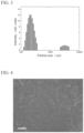
- FIG. 3 is a diagram showing a particle size distribution of a carbon nanohorn aggregate powder in a solvent in Working Example 1.
- FIG. 4 is an optical micrograph of a thin film in Working Example 1.
- FIG. 5 is an optical micrograph of a thin film in Comparative Example 1.
- FIG. 6 is an optical micrograph of a gas sensor in Working Example 2.
- FIG. 7 is a diagram showing a change in resistance value of the gas sensor in Working Example 2.
- FIG. 8 is a diagram showing a change in resistance value of a gas sensor in Working Example 3.
- FIG. 9 is a diagram showing a change in resistance value of a gas sensor in Working Example 4.
- FIG. 10 is a diagram showing a change in resistance value of a gas sensor in Working Example 5.
- FIG. 11 is a diagram showing a change in resistance value of a gas sensor in Working Example 6.
- FIG. 12 is a diagram showing a change in resistance value of a gas sensor in Working Example 7.
- a dispersion liquid of an embodiment includes a carbon nanohorn aggregate (hereinafter referred to as a “fibrous carbon nanohorn aggregate”) in which a plurality of single-walled carbon nanohorns are connected in a fibrous form, and a solvent.
- a carbon nanohorn aggregate hereinafter referred to as a “fibrous carbon nanohorn aggregate” in which a plurality of single-walled carbon nanohorns are connected in a fibrous form, and a solvent.
- the fibrous carbon nanohorn aggregate is a fibrous carbon material.
- the fibrous carbon nanohorn aggregate in the embodiment has a structure in which carbon nanohorn aggregates such as a seed type, a bud type, a dahlia type, a petal-dahlia type, and a petal type (a graphene sheet structure) are further connected one-dimensionally.
- Single-walled carbon nanohorns have a structure in which the single-walled carbon nanohorns are radially aggregated and connected in a fibrous form. That is to say, the fibrous carbon nanohorn aggregate in the embodiment includes one or more types of these carbon nanohorn aggregate in a fibrous structure.
- the fibrous carbon nanohorn aggregate in the embodiment is prepared by evaporating a target using a catalytic metal. For this reason, a catalytic metal is present inside a fibrous carbon nanohorn aggregate or a spherical carbon nanohorn aggregate.
- a fibrous carbon nanohorn aggregate is manufactured using a preparation method which will be described later, a spherical carbon nanohorn aggregate is simultaneously generated. Since the fibrous carbon nanohorn aggregate manufactured using the preparation method which will be described later includes the fibrous carbon nanohorn aggregate and the spherical carbon nanohorn aggregate, a woven carbon nanohorn aggregate has a structure in which the woven carbon nanohorn aggregate is less likely to aggregate.
- the fibrous carbon nanohorn aggregate has high dispersibility in a solution like the spherical carbon nanohorn aggregate. It should be noted that the fibrous carbon nanohorn aggregate and the spherical carbon nanohorn aggregate can be separated using centrifugal separation, a difference between sedimentation velocities after dispersion in a solvent, gel permeation chromatography, and the like. In order to maintain the dispersibility of the fibrous carbon nanohorn aggregate, it is desirable to use the fibrous carbon nanohorn aggregate and the spherical carbon nanohorn aggregate as they are without separation.
- the fibrous carbon nanohorn aggregate in the embodiment is not limited to the above-described structure as long as the single-walled carbon nanohorns are aggregated in a fibrous form.
- the single-walled carbon nanohorns have a diameter of approximately 1 nm to 5 nm and a length of 30 nm to 100 nm.
- the fibrous carbon nanohorn aggregate has a diameter of about 30 nm to 200 nm and a length of about 1 ⁇ m to 100 ⁇ m.
- the spherical carbon nanohorn aggregate has a diameter of about 30 nm to 200 nm and a substantially uniform size.
- the spherical carbon nanohorn aggregate is formed of seed type, bud type, dahlia type, petal-dahlia type, and petal type carbon nanohorn aggregates independently or in a combination thereof.
- the seed type carbon nanohorn aggregate has a shape with few or no angular projections on a spherical surface.
- the bud type carbon nanohorn aggregate has a shape in which some angular projections are present on a spherical surface.
- the dahlia type carbon nanohorn aggregate has a shape in which a large number of angular projections are present on a spherical surface.
- the petal type carbon nanohorn aggregate has a shape in which petal-like projections are present on a spherical surface.
- a petal structure is a structure in which a width is 50 nm to 200 nm, a thickness is 0.34 nm to 10 nm, and 2 to 30 graphene sheets overlap.
- the petal-dahlia type carbon nanohorn aggregate has an intermediate structure between the dahlia type carbon nanohorn aggregate and the petal type carbon nanohorn aggregate.
- the spherical carbon nanohorn aggregate is formed in a mixed state separately from the fibrous carbon nanohorn aggregate. In the formed spherical carbon nanohorn aggregate, the shape and the particle size thereof change in accordance with the type and the flow rate of a gas.
- a carbon containing a catalyst is used as a target (hereinafter referred to as a “catalyst-containing carbon target”).
- the catalyst-containing carbon target is placed in a vessel and the catalyst-containing carbon target is rotated.
- the catalyst-containing carbon target is evaporated by heating the catalyst-containing carbon target using laser ablation under a nitrogen atmosphere, under an inert atmosphere, or under a mixed atmosphere while the catalyst-containing carbon target is being rotated.
- a fibrous carbon nanohorn aggregate is obtained in a state in which the fibrous carbon nanohorn aggregate is mixed with a spherical carbon nanohorn aggregate.
- an arc discharge method and a resistance heating method can be used other than the above-described laser ablation method.
- the laser ablation method is more desirable in view of being able to continuously manufacture in atmospheric pressure at room temperature.
- a laser ablation (LA) method applied in the embodiment is a method in which, when a target is irradiated with a laser in a pulse form or continuously and an irradiation intensity is a threshold value or more, the target converts energy, and as a result, a plume is generated, a product is deposited above a substrate provided downstream of the target or is generated in a space in an apparatus and is recovered in a recovery chamber.
- a CO 2 laser, a YAG laser, an excimer laser, a semiconductor laser, and the like can be used.
- a CO 2 laser which readily allows a high output to be achieved is most desirable.
- the CO 2 laser can have an output of 1 kW/cm 2 to 1000 kW/cm 2 and can perform continuous irradiation and pulse irradiation. In order to form a carbon nanohorn aggregate, continuous irradiation is desirable.
- laser ablation a laser beam is focused using a ZnSe lens or the like and a target is irradiated with the laser beam.
- carbon nanohorn aggregates can be synthesized continuously by rotating a target.
- a rotational speed of the target can be set arbitrarily, it is particularly desirable to be 0.1 rpm to 6 rpm. If the rotational speed of the target is 0.1 rpm or more, graphitization of a carbon nanohorn aggregate can be minimized. On the other hand, if the rotational speed of the target is 6 rpm or less, an increase in amorphous carbon can be minimized.
- a laser output is preferably 15 kW/cm 2 or more and most preferably 30 kW/cm 2 to 300 kW/cm 2 . If the laser output is 15 kW/cm 2 or more, the catalyst-containing carbon target is appropriately evaporated and easily synthesized. On the other hand, if the laser output is 300 kW/cm 2 or less, an increase in amorphous carbon can be minimized.
- a pressure used in a vessel can be 13332.2 hPa (10000 Torr) or less, when the pressure is closer to a vacuum, carbon nanotubes are easily generated but a carbon nanohorn aggregate cannot be obtained. It is desirable to operate in a range of 666.61 hPa (500 Torr) to 1266.56 hPa (950 Torr) and it is more desirable to operate in the vicinity of a normal pressure (1013 hPa (1 atm ⁇ 760 Torr) for the purpose of mass production and cost reduction. Furthermore, an irradiation area can be controlled using a laser output and a degree of focusing through a lens and 0.005 cm 2 to 1 cm 2 can be used.
- the catalyst-containing carbon target have low thermal conductivity and be soft.
- the thermal conductivity is preferably 80 W/(m/k) or less, and more preferably 30 W/(m/k). It is desirable that the hardness be 40 (HDS) or more and 80 or less.
- HDS hardness
- Fe, Ni, and Co may be independently used or a combination thereof can be used.
- concentration of a catalyst can be appropriately selected, but is preferably 0.1% by mass to 10% by mass, and more preferably 0.5% by mass to 5% by mass with respect to carbon.
- concentration of the catalyst is 0.1% by mass or more, the formation of a fibrous carbon nanohorn aggregate is ensured.
- concentration of the catalyst is 10% by mass or less, an increase in target cost can be minimized.
- any temperature can be used for the inside of the vessel, it is preferably 0° C. to 100° C., and more preferably room temperature, which is also appropriate for mass production and cost reduction.
- Nitrogen gas, an inert gas, or the like is introduced independently or in a combination thereof into the vessel to make the above-described atmosphere. These gases flow into a reaction vessel and substances to be produced can be recovered using this gas flow. Furthermore, a closed atmosphere may be provided using the introduced gas.
- a atmosphere gas flow rate may be any amount, but is preferably in a range of 0.5 L/min to 100 L/min.
- a gas flow rate is controlled such that it is constant.
- the gas flow rate can be controlled such that it is constant by matching a supply gas flow rate with an exhaust gas flow rate. In the case of performing control near normal pressure, the control can be performed by extruding and exhausting a gas in the vessel using a supply gas.
- a part of this carbon skeleton may be substituted with a catalytic metal element, nitrogen atoms, or the like.
- An oxidation treatment can be performed when fine holes (opening holes) open in the spherical carbon nanohorn aggregate and the fibrous carbon nanohorn aggregate.
- defect portions such as five-membered rings and seven-membered rings are oxidized.
- a portion having five-membered rings or seven-membered rings such as a side surface and a distal end portion is opened.
- a surface functional group including oxygen is formed in an opening hole portion.
- a gas phase process and a liquid phase process can be used for the oxidation treatment.
- air, oxygen, and carbon dioxide can be used as an atmosphere gas and air is appropriate in view of cost.
- a temperature can be in a range of 300° C. to 650° C., and more appropriately 400° C. to 550° C.
- the temperature is 300° C. or higher, there is no concern concerning holes which cannot be opened due to almost no burning carbon.
- the temperature is 650° C. or lower, combustion of the entire carbon nanohorn aggregates can be minimized.
- nitric acid, sulfuric acid, hydrogen peroxide, and the like can be used.
- the nitric acid can be used in a temperature range of room temperature to 120° C. When the temperature is 120° C. or lower, an oxidizing power is not too high and oxidization is not performed more than necessary.
- the hydrogen peroxide can be used in a temperature range of room temperature to 100° C., and preferably 40° C. or higher.
- the temperature is 40° C. or higher, the oxidizing power works efficiently and opening holes can be formed efficiently.
- it is more effective to use light irradiation together with the liquid phase process.
- a catalyst (a metal) included during the formation of a fibrous carbon nanohorn aggregate can be removed because the catalyst (the metal) is dissolved in nitric acid, sulfuric acid, and hydrochloric acid.
- hydrochloric acid is appropriate in view of the ease of use.
- a temperature in which a catalyst is dissolved can be appropriately selected, when the catalyst is fully removed, it is desirable to perform heating at 70° C. or higher.
- the crystallinity of the obtained spherical carbon nanohorn aggregate and fibrous carbon nanohorn aggregate can be improved using heat treatment in an inert gas, hydrogen, or a vacuum atmosphere.
- a heat treatment temperature can be 800° C. to 2000° C., preferably 1000° C. to 1500° C.
- surface functional groups formed through oxidation treatment which forms opening holes can also be removed through this heat treatment.
- This heat treatment temperature can be 150° C. to 2000° C.
- the heat treatment temperature is preferably 150° C. to 600° C.
- the heat treatment temperature is preferably 600° C. or higher.
- a surface functional group can be removed through reduction. The reduction of the surface functional group can be performed under a gas atmosphere such as hydrogen or under a liquid atmosphere such as hydrazine.
- the solvent is not particularly limited, but examples of the solvent include alcohol-based solvents such as water, methanol, ethanol, n-propanol, isopropanol, n-butanol, isobutanol, t-butanol, pentanol, and hexanol, aromatic hydrocarbon solvents such as benzene, toluene, xylene, and ethylbenzene, aliphatic or alicyclic hydrocarbon solvents such as hexane, heptane, and cyclohexane, organic halogen compound solvents such as methyl chloride, methyl bromide, methyl iodide, methylene dichloride, carbon tetrachloride, trichloroethylene, dichloromethane, dichloroethane, perchloroethylene, and ortho-dichlorobenzene, ether-based solvents such as diethyl ether
- the content of the fibrous carbon nanohorn aggregate is appropriately adjusted in accordance with the viscosity and the like obtained for the dispersion liquid, and for example, there is preferably 0.1 mg to 20 mg of the fibrous carbon nanohorn aggregate per 1 mL of solvent, and more preferably 1 mg to 5 mg.
- the content of the fibrous carbon nanohorn aggregate is 0.1 mg or more per 1 mL of a solvent, in a gas sensor which will be described later, a thin film obtained by drying a coating film formed by applying this dispersion liquid to a substrate can adsorb a gas.
- the content of the fibrous carbon nanohorn aggregate is 20 mg or less per 1 mL of a solvent, the aggregation of the fibrous carbon nanohorn aggregate in the solvent is minimized.
- Such a fibrous carbon nanohorn aggregate has superior conductivity and solvent dispersibility and a larger specific surface area than that of the spherical carbon nanohorn aggregate. Furthermore, it is expected that the fibrous carbon nanohorn aggregate will be able to be applied to various technical fields to a greater extent than that of the spherical carbon nanohorn aggregate.
- a binder such as a binder, a dispersing agent, a plasticizer, a flow control agent, a thickener, and the like may be appropriately contained in the dispersion liquid in the embodiment within a range in which the effects of the invention are not inhibited.
- a binder it is desirable that a binder be contained in the dispersion liquid within a range in which the fibrous carbon nanohorn aggregate does not inhibit the adsorption of a gas to be detected which will be described later. Thus, this makes it difficult for the thin film formed using this dispersion to separate from the substrate or the like.
- the fibrous carbon nanohorn aggregate having the above characteristics is uniformly dispersed in the solvent, even if two weeks or more have passed from the production, there is no significant aggregation and settling of a fibrous carbon nanohorn aggregate and a fibrous carbon nanohorn aggregate is stably dispersed in the solvent. Furthermore, according to the dispersion liquid in the embodiment, it is possible to form a thin film containing a fibrous carbon nanohorn aggregate and having a uniform thickness and a uniform content of a fibrous carbon nanohorn aggregate.
- a fibrous carbon nanohorn aggregate is dispersed in a solvent (a dispersion medium) using an ultrasonic dispersion treatment.
- a dispersion liquid obtained by uniformly dispersing the fibrous carbon nanohorn aggregate in the solvent is obtained.
- an amount of fibrous carbon nanohorn aggregates added to the solvent is as follows.
- a method for applying an ultrasonic dispersion treatment to a solvent added to a fibrous carbon nanohorn aggregate is not particularly limited, for example, a method of accommodating a solvent added to a fibrous carbon nanohorn aggregate in a vessel such as a beaker and applying ultrasonic waves to the vessel using an apparatus configured to perform an ultrasonic dispersion treatment is an exemplary example.
- An apparatus configured to perform ultrasonic dispersion treatment is not particularly limited as long as the apparatus configured to perform ultrasonic dispersion treatment is an apparatus capable of applying ultrasonic waves to a solvent containing a fibrous carbon nanohorn aggregate accommodated in a vessel, and for example, an ultrasonic cleaner and the like are exemplary examples.
- a time during which ultrasonic dispersion treatment is performed is not particularly limited, the time is appropriately adjusted in accordance with an amount of fibrous carbon nanohorn aggregate with respect to a solvent and the like.
- a temperature at which ultrasonic dispersion treatment is performed is not particularly limited, the temperature is appropriately adjusted to a temperature range in which a solvent does not evaporate.
- a dispersion liquid obtained by uniformly and stably dispersing a fibrous carbon nanohorn aggregate in a solvent can be obtained.
- FIG. 1 is a schematic diagram showing a gas sensor in an embodiment.
- a gas sensor 10 in the embodiment includes an adsorbent 11 which includes a fibrous carbon nanohorn aggregate in which a plurality of single-walled carbon nanohorns are aggregated in a fibrous form and a measurement unit 12 which measures the electrical characteristics of the adsorbent 11 . Furthermore, as shown in FIG. 1 , for example, the adsorbent 11 is provided on one surface (an upper surface) 13 a of a substrate 13 .
- the gas sensor 10 in the embodiment may include a current (voltage) application apparatus (not shown) configured to apply a constant current (a voltage) to the adsorbent 11 so that a gas to be detected is adsorbed on the adsorbent 11 as will be described later.
- the adsorbent 11 is formed of a thin film obtained by drying a coating film formed by applying the above-described dispersion liquid to one surface 13 a of the substrate 13 . That is to say, the adsorbent 11 is a thin film formed of a fibrous carbon nanohorn aggregate.
- the adsorbent 11 is a thin film having a uniform thickness and a uniform content of a fibrous carbon nanohorn aggregate. Since the thickness of the adsorbent 11 is uniform, the conductivity (surface resistance) is also uniform as a whole.
- the adsorbent 11 is formed of a fibrous carbon nanohorn aggregate, the adsorbent 11 is a porous body having a plurality of fine holes throughout and has a portion (an adsorption site) configured to adsorb a gas at a molecular level which will be described later.
- a thickness of the adsorbent 11 is not particularly limited, for example, the thickness is preferably 100 nm to 100 ⁇ m, and more preferably 200 nm to 5 ⁇ m.
- the thickness of the adsorbent 11 is 200 nm or more, it is possible to adsorb a sufficient amount of gas to be detected for detection. On the other hand, when the thickness of the adsorbent 11 is 5 ⁇ m or less, peeling of the adsorbent 11 from the substrate 13 due to scratching or the like can be prevented.
- the measurement unit 12 is connected to the adsorbent 11 , for example, via a lead wire 14 . Furthermore, the lead wire 14 is brought into contact with the adsorbent 11 using a terminal.
- the measurement unit 12 is for measuring the conductivity (for example, surface resistance (sheet resistance)) of the adsorbent 11 which changes when a gas to be detected is adsorbed.
- a sheet resistance measurement apparatus or the like is used as the measurement unit 12 .
- the surface resistance of the adsorbent 11 is measured, for example, by a four terminal method using a sheet resistance measurement apparatus.
- the substrate 13 is not particularly limited as long as the substrate 13 is made of an insulating material.
- materials which can be used for the substrate 13 include insulating polymer materials, polyethylene terephthalate (PET), polyimide (PI), polyethylene naphthalate (PEN), polyethersulfone (PES), polyetheretherketone (PEEK), polycarbonate (PC), polypropylene (PP), polyamide (PA), polyacrylic (PAC), acrylic, amorphous polyolefin resins, cyclic polyolefin resins, aliphatic cyclic polyolefin, norbornene thermoplastic resins, Parylene, and the like.
- examples of materials which can be used for the substrate 13 include phenol paper, epoxy paper, glass epoxy materials, quartz, soda glass, and heat resistant glass for printed wiring boards and the like. Furthermore, examples of materials which can be used for the substrate 13 include silicon oxide, silicon nitride, aluminum oxide, hafnium oxide, zirconium oxide, and titanium oxide. The substrate 13 may be made of one of these insulating materials or may be a laminate made of two or more of these insulating materials.
- Examples of the lead wire 14 include those generally used in electrical circuits.
- the gas sensor 10 in the embodiment is, for example, a two terminal resistance change type gas sensor in which the adsorbent 11 formed of a thin film provided on the one surface 13 a of the substrate 13 functions as a gas sensitive part.
- a gas to be detected is supplied to the adsorbent 11 that is a gas sensitive part in a state in which a constant current (a voltage) is applied to the adsorbent 11 , gas molecules are adsorbed on the adsorbent 11 and the conductivity (a resistance value) of the adsorbent 11 changes.
- gas molecules adsorbed on the adsorbent 11 are desorbed and the conductivity of the adsorbent 11 returns to the original state thereof.
- examples of a gas to be detected include nitrogen oxides (NO X ), carbon oxides (CO X ), sulfur oxides (SO X ), ozone, ammonia, oxygen, hydrogen, halogens, hydrocarbons such as hexane, alcohols such as ethanol, methanol, isopropyl alcohol, aldehydes, ethers, ketones such as acetone and methyl ethyl ketone, nitro compounds, aromatic compounds such as benzene and toluene, organic halogen compounds such as dichloroethane, and the like.
- a gas to be detected can be detected when the measurement unit 12 measures a change in the conductivity of the adsorbent 11 in the process of adsorption and desorption of the gas to be detected.
- a manufacturing method of the gas sensor in the embodiment includes a step of applying a dispersion liquid containing a fibrous carbon nanohorn aggregate to a substrate and forming an adsorbent containing a fibrous carbon nanohorn aggregate.
- the manufacturing method of the gas sensor in the embodiment includes a step of forming a coating film by applying the above-described dispersion liquid to the one surface 13 a of the substrate 13 and forming an adsorbent formed of a thin film of a fibrous carbon nanohorn aggregate by drying this coating film.
- a method of applying a dispersion liquid to the substrate 13 is not particularly limited and examples of the application method include conventional wet coating methods such as a bar coating method, a flow coating method, a dip coating method, a spin coating method, a roll coating method, a spray coating method, a meniscus coating method, a gravure coating method, a suction coating method, and a brush coating method.
- conventional wet coating methods such as a bar coating method, a flow coating method, a dip coating method, a spin coating method, a roll coating method, a spray coating method, a meniscus coating method, a gravure coating method, a suction coating method, and a brush coating method.
- a method for drying a coating film is not particularly limited and examples of the drying method include a method of performing drying at 50° C. to 250° C. using a general oven or a method of performing drying at room temperature.
- a gas sensor which includes a fibrous carbon nanohorn aggregate and the adsorbent 11 including a uniformly dispersed fibrous carbon nanohorn aggregate is obtained.
- FIG. 2 is a schematic diagram showing a gas sensor according to an embodiment.
- a gas sensor 20 in the embodiment includes a plurality of electrodes 21 and 22 , an adsorption layer 23 provided between the electrodes 21 and 22 , and a measurement unit 24 which measures the electrical characteristics of the adsorption layer 23 . Furthermore, as shown in FIG. 2 , the electrodes 21 and 22 and the adsorption layer 23 are provided, for example, on one surface (an upper surface) 25 a of a substrate 25 . In addition, the electrode 21 and the electrode 22 are provided with a predetermined distance therebetween on the one surface 25 a of the substrate 25 .
- the gas sensor 20 in the embodiment may include a current (voltage) application apparatus (not shown) configured to apply a constant current (a voltage) to the adsorption layer 23 so that a gas to be detected is adsorbed on the adsorption layer 23 as will be described later.
- a current (voltage) application apparatus not shown
- a constant current (a voltage) to the adsorption layer 23 so that a gas to be detected is adsorbed on the adsorption layer 23 as will be described later.
- the electrodes 21 and 22 are not particularly limited as long as the electrodes 21 and 22 are formed of a conductor (a conductive material).
- a conductor a conductive material
- examples of materials which can be used for the electrodes 21 and 22 include metals (including nanoparticles of gold, silver, and copper), indium tin oxide (ITO), metal oxides such as zinc oxide and tin oxide, conductive polymers, carbon nanotubes, carbon-based conductive materials such as graphene, and the like.
- the adsorption layer 23 is formed of, for example, a thin film obtained by drying a coating film formed by applying the above-described dispersion liquid to the one surface 25 a of the substrate 25 . That is to say, the adsorption layer 23 is a thin film formed of a fibrous carbon nanohorn aggregate.
- the adsorption layer 23 is a thin film having a uniform thickness and a uniform content of fibrous carbon nanohorn aggregates. Since the adsorption layer 23 has a uniform thickness, the conductivity (surface resistance) of the adsorption layer 23 is also uniform.
- the adsorption layer 23 is formed of a fibrous carbon nanohorn aggregate, the adsorption layer 23 is a porous body having a plurality of fine holes throughout and has a portion (an adsorption site) configured to adsorb a gas at a molecular level which will be described later.
- a thickness of the adsorption layer 23 is not particularly limited, but is, for example, preferably 100 nm to 100 ⁇ m, and more preferably 200 nm to 5 ⁇ m.
- the thickness of the adsorption layer 23 is 200 nm or more, it is possible to adsorb a sufficient amount of gas to be detected for detection. On the other hand, if the thickness of the adsorption layer 23 is 5 ⁇ m or less, peeling of the adsorption layer 23 from the substrate 25 due to scratching or the like can be prevented.
- the measurement unit 24 is connected to, for example, the electrodes 21 and 22 via the lead wire 26 . Furthermore, the lead wire 26 is brought into contact with the electrodes 21 and 22 using a terminal. That is to say, the measurement unit 24 is connected to the adsorption layer 23 via the lead wire 26 and the electrodes 21 and 22 .
- the measurement unit 22 is for measuring the conductivity (for example, surface resistance (sheet resistance)) of the adsorption layer 23 which changes due to the adsorbed gas to be detected.
- the measurement unit 24 the same measurement unit 12 as described above is used.
- the same substrate 13 as described above is used as the substrate 25 .
- the same lead wire 14 as described above is used as the lead wire 26 .
- the gas sensor 20 in the embodiment is, for example, a two terminal resistance change type gas sensor in which the adsorption layer 23 formed of a thin film provided on the one surface 25 a of the substrate 25 functions as a gas sensitive part.
- a gas to be detected is supplied to the adsorption layer 23 that is a gas sensitive part in a state in which a constant current (a voltage) is applied to the electrode 21 and the electrode 22 , gas molecules adsorb to the adsorption layer 23 and the conductivity (the resistance value) of the adsorption layer 23 changes.
- gas molecules which have been adsorbed on the adsorption layer 23 desorb and the conductivity of the adsorption layer 23 returns to the original state thereof.
- examples of the gas to be detected include the same gases as in the gas sensor 10 in the first exemplary embodiment.
- the gas sensor in the embodiment by measuring a change in conductivity of the adsorption layer 23 in the process of adsorption and desorption of a gas to be detected using the measurement unit 24 , it is possible to detect the gas to be detected.
- a manufacturing method of the gas sensor in the embodiment includes a step of applying a dispersion liquid containing a fibrous carbon nanohorn aggregate to a substrate and forming an adsorption layer containing a fibrous carbon nanohorn aggregate.
- the manufacturing method of the gas sensor in the embodiment includes a step of forming a coating film by applying the above-described dispersion liquid between the electrode 21 and the electrode 22 formed above the one surface 25 a of the substrate 25 in advance and forming the adsorption layer 23 formed of a thin film containing a fibrous carbon nanohorn aggregate by drying this coating film.
- the same method as the applying method in the first exemplary embodiment may be used.
- the same method as the drying method in the first exemplary embodiment may be used.
- a gas sensor including the adsorption layer 23 which contains a fibrous carbon nanohorn aggregate and in which a fibrous carbon nanohorn aggregate is uniformly dispersed is obtained.
- a powder obtained by subjecting CO 2 laser ablation to a catalyst-containing carbon target containing 1% by mass of iron as a catalyst under a nitrogen atmosphere and containing a fibrous carbon nanohorn aggregate and a spherical carbon nanohorn aggregate mixed together (hereinafter referred to as a “carbon nanohorn aggregate powder”) was obtained. Description will be provided in detail below.
- a catalyst-containing carbon target containing 1% by mass of iron was placed in a vessel under a nitrogen atmosphere. A temperature in the vessel was room temperature. A gas flow rate in the vessel was adjusted to 10 L/cm 2 . The catalyst-containing carbon target was rotated at 2 rpm.
- the rotating catalyst-containing carbon target was irradiated with a CO 2 gas laser beam having an energy density of 100 kW/cm 2 to 300 kW/cm 2 .
- a pressure in the vessel was controlled to be 933.254 hPa to 1266.559 hPa (700 Torr to 950 Torr).
- a dispersion liquid was prepared by applying ultrasonic waves to the glass beaker having the above-described mixture accommodated therein for 30 minutes using an ultrasonic cleaner (trade name: VS-100III manufactured by As One Corporation) and subjecting dispersion treatment to the carbon nanohorn aggregate powder in ethanol.
- an ultrasonic cleaner trade name: VS-100III manufactured by As One Corporation
- a coating film was formed above a polyimide substrate having a thickness of 75 ⁇ m and a vertical length of 1 cm ⁇ a horizontal length of 1 cm by dropping-cast 100 ⁇ L of the obtained dispersion liquid above this polyimide substrate.
- FIG. 3 is a diagram showing a particle size distribution of a carbon nanohorn aggregate powder in a solvent. From FIG. 3 , particle size distributions in a region of 100 nm to 300 nm and 2000 nm to 5000 nm was confirmed. 100 nm to 300 nm correspond to spherical carbon nanohorn aggregates and 2000 nm to 5000 nm correspond to fibrous carbon nanohorn aggregates. In addition, it could be seen that the spherical carbon nanohorn aggregates and the fibrous carbon nanohorn aggregates are substantially mono-dispersed in ethanol. Therefore, it could be seen that the fibrous carbon nanohorn aggregates have a high dispersibility.
- a thin film formed of a carbon nanohorn aggregate powder was formed above the polyimide substrate by drying this coating film at 65° C. using an oven.
- FIG. 4 shows an optical micrograph.
- a dispersion liquid was prepared by applying ultrasonic waves to the glass beaker having the above-described mixture accommodated therein for 150 minutes using an ultrasonic cleaner (trade name: VS-100III manufactured by As One Corporation) and subjecting dispersion treatment to the single-walled carbon nanotube powder in ethanol. Since aggregates significantly remained in the single-walled carbon nanotube powder, a dispersion treatment time was 150 minutes.
- an ultrasonic cleaner trade name: VS-100III manufactured by As One Corporation
- a coating film was formed above a polyimide substrate having a thickness of 75 ⁇ m and a vertical length of 1 cm ⁇ a horizontal length of 1 cm by dropping-cast 100 ⁇ L of the obtained dispersion liquid above this polyimide substrate.
- a thin film formed of a carbon nanohorn aggregate powder was formed above the polyimide substrate by drying this coating film at 65° C. using an oven.
- FIG. 5 shows an optical micrograph.
- Comparative Example 1 From the optical micrograph of FIG. 5 , the thin film formed of the single-walled carbon nanotube powder of Comparative Example 1 was significantly non-uniform and discontinuous. For this reason, in Comparative Example 1, as indicated by a black dashed line in FIG. 5 , it was confirmed that an exposed portion in the polyimide substrate (a portion which was not covered with a thin film made of a single-walled carbon nanotube powder in the polyimide substrate) was present.
- a dispersion liquid was prepared by applying ultrasonic waves to the glass beaker having the above-described mixture accommodated therein for 30 minutes using an ultrasonic cleaner (trade name: VS-100III manufactured by As One Corporation) and subjecting dispersion treatment to the carbon nanohorn aggregate powder in ethanol.
- an ultrasonic cleaner trade name: VS-100III manufactured by As One Corporation
- a coating film was formed by filling a Hamilton gas tight syringe (type: 1705TLL) with the obtained dispersion liquid and applying the obtained dispersion liquid above a substrate linearly using a dispensing apparatus (trade name: FAD-320S and NANO MASTER SMP-II manufactured by Musashi Engineering Co., Ltd.).
- a double thread plastic needle (trade name: DPN-20G-1 manufactured by Musashi Engineering Co., Ltd.) was used.
- An interval between the substrate and a distal end of the syringe needle was set to 0.1 mm, a syringe sweep speed was set to 8.0 mm/s, and a stage temperature was set to 40° C.
- Droplets (a dispersion liquid) were discharged onto the substrate under the conditions of a normal mode 24 (a motor rotational speed) described in the manual of a dispensing apparatus (trade name: NANO MASTER SMP-III manufactured by Musashi Engineering Co., Ltd.).
- a polyimide substrate having a thickness of thickness of 75 ⁇ m and a vertical length of 1 cm ⁇ a horizontal length of 1 cm, on which a plurality of gold electrodes having a thickness of 50 nm and a width of 100 ⁇ m are vapor-deposited in parallel was used.
- the dispersion liquid was applied in a direction orthogonal to a longitudinal direction of the gold electrodes provided above the polyimide substrate (in a direction of an arrow shown in FIG. 6 ). It should be noted that, in order to ensure sufficient conductivity of the thin film obtained by drying the coating film, linear application of the dispersion liquid to the substrate was repeated 36 times.
- a gas sensor was obtained by drying this coating film 65° C. using an oven and forming a thin film made of a carbon nanohorn aggregate powder above the polyimide substrate.
- FIG. 6 shows an optical micrograph.
- a region surrounded by a broken line corresponds to one gas sensor.
- a band-like region at a center in FIG. 6 is a thin film made of a carbon nanohorn aggregate powder.
- Ethanol gas was supplied to the gas sensor obtained as described above using the following method.
- a bubbling method was used as an ethanol gas supply method and the flow rate of ethanol gas was controlled by a mass flow controller (trade name: SEC-4500M and SEC-E40 manufactured by Horiba Estec Co., Ltd.)
- nitrogen gas was bubbled into ethanol (purity: 99.5%; an EL grade; manufactured by Kanto Chemical Co., Ltd.) at a temperature of 20° C. under normal pressure to obtain ethanol vapor having a concentration of 6%.
- concentration of ethanol vapor was controlled by mixing ethanol and nitrogen gas at a predetermined flow ratio.
- the total flow rate of a gas supplied to the gas sensor was set to be 1.0 L/min.
- a change in resistance value of the gas sensor along with the supply and the stop of ethanol gas was measured as follows.
- the gas sensor obtained as described above is stored in a chamber and a semiconductor parameter analyzer (trade name: Agilent 4155C manufactured by Agilent Technologies) was connected to gold electrodes of this gas sensor via a lead wire. A voltage was measured with a bias current of 5 ⁇ A applied between the two gold electrodes. Furthermore, data points were acquired at an integration time of 240 ms and at 0.5 second intervals.
- a semiconductor parameter analyzer trade name: Agilent 4155C manufactured by Agilent Technologies
- a resistance value of the gas sensor was measured in a state in which only nitrogen gas was supplied and this was used as a reference value R 0 . Subsequently, a resistance value R of the gas sensor was measured in a state in which ethanol gas was supplied.
- FIG. 7 shows the results.
- a vertical axis indicates a resistance value R with respect to a reference value R 0 ( ⁇ R/R 0 (%)) and a horizontal axis indicates an elapsed time.
- a gas sensor was manufactured in the same manner as in Working Example 2.
- 1,2-Dichloroethane was supplied to the gas sensor obtained as described above in the following manner.
- a bubbling method was used as a method of supplying 1,2-dichloroethane and the flow rate of 1,2-dichloroethane was controlled using a mass flow controller (trade name: SEC-4500M and SEC-E40 manufactured by Horiba Estec Co., Ltd.).
- 1,2-dichloroethane purity: 99.5% or higher; manufactured by Kanto Chemical Co., Ltd.
- 1,2-dichloroethane vapor having a concentration of 8% was obtained.
- concentration of 1,2-dichloroethane vapor (1,2-dichloroethane) was controlled by mixing 1,2-dichloroethane and nitrogen gas at a predetermined flow ratio.
- the total flow rate of a gas supplied to the gas sensor was set to 1.2 L/min.
- the gas sensor obtained as described above was stored in the chamber and a semiconductor parameter analyzer (trade name: Agilent 4155C manufactured by Agilent Technologies) was connected to gold electrodes of the gas sensor via a lead wire. A voltage was measured with a 5 ⁇ A of bias current applied between two gold electrodes. Furthermore, data points were acquired at an integration time of 500 ms at 1 second intervals.
- a semiconductor parameter analyzer trade name: Agilent 4155C manufactured by Agilent Technologies
- a resistance value of the gas sensor was measured in a state in which only nitrogen gas was supplied and this was used as a reference value R 0 .
- 1,2-dichloroethane was supplied for only 30 seconds (a lower arrow portion in FIG. 8 ) and a resistance value R of the gas sensor at that time was measured.
- only nitrogen gas was supplied to the gas sensor.
- the same measurement was performed by changing the concentration of 1,2-dichloroethane in the chamber.
- FIG. 8 shows the results.
- a vertical axis indicates a resistance value R with respect to a reference value R 0 ( ⁇ R/R 0 (%)) and a horizontal axis indicates an elapsed time.
- a gas sensor was manufactured in the same manner as in Working Example 2.
- a resistance value of the gas sensor was measured in the same manner as in Working Example 3 except that acetone (purity: 99.8%; an EL grade; manufactured by Kanto Chemical Co., Ltd.) is used as a gas to be detected supplied to the gas sensor obtained as described above.
- FIG. 9 shows the results.
- a vertical axis indicates a resistance value R with respect to a reference value R 0 ( ⁇ R/R 0 (%)) and a horizontal axis indicates an elapsed time.
- a gas sensor was manufactured in the same manner as in Working Example 2.
- a resistance value of the gas sensor was measured in the same manner as in Working Example 3 except that n-hexane (purity: 99% or higher; manufactured by Sigma-Aldrich) is used as a gas to be detected supplied to the gas sensor obtained as described above.
- FIG. 10 shows the results.
- a vertical axis indicates a resistance value R with respect to a reference value R 0 ( ⁇ R/R 0 (%)) and a horizontal axis indicates an elapsed time.
- a gas sensor was manufactured in the same manner as in Working Example 2.
- a resistance value of the gas sensor was measured in the same manner as in Working Example 3 except that ethanol (purity: 99.5%; an EL grade; manufactured by Kanto Chemical Co., Ltd.) is used as a gas to be detected supplied to the gas sensor obtained as described above.
- FIG. 11 shows the results.
- a vertical axis indicates a resistance value R with respect to a reference value R 0 ( ⁇ R/R 0 (%)) and a horizontal axis indicates an elapsed time.
- a gas sensor was manufactured in the same manner as in Working Example 2.
- a resistance value of the gas sensor was measured in the same manner as in Working Example 3 except that toluene (purity: 99.7% or higher; manufactured by Kanto Chemical Co., Ltd.) is used as a gas to be detected supplied to the gas sensor obtained as described above.
- FIG. 12 shows the results.
- a vertical axis indicates a resistance value R with respect to a reference value R 0 ( ⁇ R/R 0 (%)) and a horizontal axis indicates an elapsed time.
Landscapes
- Chemical & Material Sciences (AREA)
- Organic Chemistry (AREA)
- Engineering & Computer Science (AREA)
- Chemical Kinetics & Catalysis (AREA)
- Analytical Chemistry (AREA)
- Nanotechnology (AREA)
- Materials Engineering (AREA)
- Inorganic Chemistry (AREA)
- Life Sciences & Earth Sciences (AREA)
- Immunology (AREA)
- Physics & Mathematics (AREA)
- Electrochemistry (AREA)
- Biochemistry (AREA)
- General Health & Medical Sciences (AREA)
- General Physics & Mathematics (AREA)
- Health & Medical Sciences (AREA)
- Pathology (AREA)
- Crystallography & Structural Chemistry (AREA)
- Dispersion Chemistry (AREA)
- Carbon And Carbon Compounds (AREA)
- Investigating Or Analyzing Materials By The Use Of Fluid Adsorption Or Reactions (AREA)
- Colloid Chemistry (AREA)
- Catalysts (AREA)
Abstract
Description
-
- 10, 20 Gas sensor
- 11 Adsorbent
- 12, 24 Measurement unit
- 13, 25 Substrate
- 14, 26 Lead wire
- 21, 22 Electrode
- 23 Adsorption layer
Claims (3)
Applications Claiming Priority (1)
| Application Number | Priority Date | Filing Date | Title |
|---|---|---|---|
| PCT/JP2017/005129 WO2018146810A1 (en) | 2017-02-13 | 2017-02-13 | Dispersion liquid, preparation method thereof, gas sensor and method for manufacturing same |
Publications (2)
| Publication Number | Publication Date |
|---|---|
| US20200003716A1 US20200003716A1 (en) | 2020-01-02 |
| US11650175B2 true US11650175B2 (en) | 2023-05-16 |
Family
ID=63107946
Family Applications (1)
| Application Number | Title | Priority Date | Filing Date |
|---|---|---|---|
| US16/484,700 Active 2039-03-25 US11650175B2 (en) | 2017-02-13 | 2017-02-13 | Dispersion liquid, preparation method thereof, gas sensor, and method for manufacturing same |
Country Status (3)
| Country | Link |
|---|---|
| US (1) | US11650175B2 (en) |
| JP (1) | JP6856079B2 (en) |
| WO (1) | WO2018146810A1 (en) |
Families Citing this family (5)
| Publication number | Priority date | Publication date | Assignee | Title |
|---|---|---|---|---|
| WO2020149283A1 (en) * | 2019-01-16 | 2020-07-23 | 日本電気株式会社 | Carbon nano brush antistatic coating material |
| JP7283083B2 (en) * | 2019-01-16 | 2023-05-30 | 日本電気株式会社 | Carbon nanobrush adhesive/adhesive |
| JP7192988B2 (en) * | 2019-06-12 | 2022-12-20 | 日本電気株式会社 | composite material |
| EP3992622B1 (en) * | 2020-11-03 | 2023-06-28 | Institutul National de Cercetare-Dezvoltare Pentru Microtehnologie - IMT Bucuresti INCD | Quaternary hydrophilic nanohybrid composition for resistive humidity sensors |
| US12535443B2 (en) * | 2021-03-22 | 2026-01-27 | Fariborz Taghipour | Photo-activated sensor for analyzing chemical and biological fluids |
Citations (7)
| Publication number | Priority date | Publication date | Assignee | Title |
|---|---|---|---|---|
| WO2001044796A1 (en) | 1999-12-15 | 2001-06-21 | Board Of Trustees Of The Leland Stanford Junior University | Carbon nanotube devices |
| JP2006329802A (en) | 2005-05-26 | 2006-12-07 | Kyushu Univ | Carbon nanotube sensor and manufacturing method thereof |
| JP2008185495A (en) | 2007-01-31 | 2008-08-14 | National Institute Of Advanced Industrial & Technology | Gas sensor |
| JP2010038692A (en) | 2008-08-04 | 2010-02-18 | Osaka Univ | Gas detecting element |
| US20120202060A1 (en) * | 2009-10-16 | 2012-08-09 | Nec Corporation | Nanotube-nanohorn complex and method of manufacturing the same |
| WO2016147909A1 (en) | 2015-03-16 | 2016-09-22 | 日本電気株式会社 | Fibrous carbon nanohorn aggregates and method for producing same |
| WO2016208170A1 (en) | 2015-06-22 | 2016-12-29 | 日本電気株式会社 | Nano-carbon composite material and method for producing same |
-
2017
- 2017-02-13 JP JP2018566732A patent/JP6856079B2/en active Active
- 2017-02-13 US US16/484,700 patent/US11650175B2/en active Active
- 2017-02-13 WO PCT/JP2017/005129 patent/WO2018146810A1/en not_active Ceased
Patent Citations (7)
| Publication number | Priority date | Publication date | Assignee | Title |
|---|---|---|---|---|
| WO2001044796A1 (en) | 1999-12-15 | 2001-06-21 | Board Of Trustees Of The Leland Stanford Junior University | Carbon nanotube devices |
| JP2006329802A (en) | 2005-05-26 | 2006-12-07 | Kyushu Univ | Carbon nanotube sensor and manufacturing method thereof |
| JP2008185495A (en) | 2007-01-31 | 2008-08-14 | National Institute Of Advanced Industrial & Technology | Gas sensor |
| JP2010038692A (en) | 2008-08-04 | 2010-02-18 | Osaka Univ | Gas detecting element |
| US20120202060A1 (en) * | 2009-10-16 | 2012-08-09 | Nec Corporation | Nanotube-nanohorn complex and method of manufacturing the same |
| WO2016147909A1 (en) | 2015-03-16 | 2016-09-22 | 日本電気株式会社 | Fibrous carbon nanohorn aggregates and method for producing same |
| WO2016208170A1 (en) | 2015-06-22 | 2016-12-29 | 日本電気株式会社 | Nano-carbon composite material and method for producing same |
Non-Patent Citations (4)
| Title |
|---|
| International Search Report for PCT/JP2017/005129 dated Mar. 7, 2017 [PCT/ISA/210]. |
| Machine translation JP2006-329802 (Year: 2006). * |
| Ryota Yuge et al., "Preparation and Characterization of Newly Discovered Fibrous Aggregates of Single-Walled Carbon Nanohorns", Advanced Materials, May 25, 2016, pp. 7174-7177, vol. 28, No. 33. |
| Suehiro et al. (Application of dielectrophoresis to fabrication of carbon nanohorn gas sensor, Journal of Electrostatics 64 (2006) 408-415). (Year: 2006). * |
Also Published As
| Publication number | Publication date |
|---|---|
| US20200003716A1 (en) | 2020-01-02 |
| JPWO2018146810A1 (en) | 2019-11-07 |
| JP6856079B2 (en) | 2021-04-07 |
| WO2018146810A1 (en) | 2018-08-16 |
Similar Documents
| Publication | Publication Date | Title |
|---|---|---|
| US11650175B2 (en) | Dispersion liquid, preparation method thereof, gas sensor, and method for manufacturing same | |
| Septiani et al. | The development of gas sensor based on carbon nanotubes | |
| US7341498B2 (en) | Method of irradiating field emission cathode having nanotubes | |
| Nishimura et al. | Enhancement of the electron transfer rate in carbon nanotube flexible electrochemical sensors by surface functionalization | |
| Wang et al. | Oxidative treatment of multi-wall carbon nanotubes with oxygen dielectric barrier discharge plasma | |
| Jung et al. | Gas-sensing properties of multi-walled carbon-nanotube sheet coated with NiO | |
| Ren et al. | High-performance flexible fully-printed all-carbon thin film transistors and ultrasensitive NH 3 sensors | |
| US20110082034A1 (en) | Nanotube-nanohorn complex and method of manufacturing the same | |
| Sivalingam et al. | Influence of the concentration of reducing agent on gold nanoparticles decorated reduced graphene oxide and its ammonia sensing performance | |
| Vizireanu et al. | Aging phenomena and wettability control of plasma deposited carbon nanowall layers | |
| Du et al. | Investigation of gas sensing materials tin oxide nanofibers treated by oxygen plasma | |
| Alfè et al. | Tuning the surface morphology of self-assembled graphene-like thin films through pH variation | |
| Huang et al. | Functionalization of graphene by atmospheric pressure plasma jet in air or H2O2 environments | |
| Lone et al. | Growth of single wall carbon nanotubes using PECVD technique: An efficient chemiresistor gas sensor | |
| CN101450797B (en) | Method for processing carbon nanotube, carbon nanotube and carbon nanotube element | |
| Kang et al. | Work-function engineering of carbon nanotube transparent conductive films | |
| Yuge et al. | Preparation, electrical properties, and supercapacitor applications of fibrous aggregates of single-walled carbon nanohorns | |
| JP7192988B2 (en) | composite material | |
| Wong et al. | Intense pulsed light conversion of anatase to rutile TiO 2 for hybrid TiO 2-SnO 2/MWCNTs/PVB room temperature VOCs sensor | |
| JP2010177214A (en) | Field emission device made of laser and/or plasma-treated carbon nanotube mat, film or ink | |
| Kang et al. | High-sensitivity gas sensor using electrically conductive and porosity-developed carbon nanofiber | |
| Pakdee et al. | Growth of MWCNTs on Plasma Ion‐Bombarded Thin Gold Films and Their Enhancements of Ammonia‐Sensing Properties Using Inkjet Printing | |
| WO2022031782A1 (en) | Carbogenic nanoparticle-conducting polymer materials and inks for voc and moisture sensing, and methods of making and using the same | |
| Liu et al. | Superamphiphilic Ag–CNTs electrode by atmosphere plasma treatment | |
| Yoo et al. | The density control of carbon nanotubes using spin-coated nanoparticle and its application to the electron emitter with triode structure |
Legal Events
| Date | Code | Title | Description |
|---|---|---|---|
| AS | Assignment |
Owner name: NEC CORPORATION, JAPAN Free format text: ASSIGNMENT OF ASSIGNORS INTEREST;ASSIGNORS:TONOUCHI, NORIYUKI;YUGE, RYOTA;REEL/FRAME:050004/0737 Effective date: 20190731 |
|
| FEPP | Fee payment procedure |
Free format text: ENTITY STATUS SET TO UNDISCOUNTED (ORIGINAL EVENT CODE: BIG.); ENTITY STATUS OF PATENT OWNER: LARGE ENTITY |
|
| STPP | Information on status: patent application and granting procedure in general |
Free format text: NON FINAL ACTION MAILED |
|
| STPP | Information on status: patent application and granting procedure in general |
Free format text: RESPONSE TO NON-FINAL OFFICE ACTION ENTERED AND FORWARDED TO EXAMINER |
|
| STPP | Information on status: patent application and granting procedure in general |
Free format text: FINAL REJECTION MAILED |
|
| STPP | Information on status: patent application and granting procedure in general |
Free format text: RESPONSE AFTER FINAL ACTION FORWARDED TO EXAMINER |
|
| STCF | Information on status: patent grant |
Free format text: PATENTED CASE |