US11650126B2 - Systems and methods for automatic visual inspection of defects in ophthalmic lenses - Google Patents
Systems and methods for automatic visual inspection of defects in ophthalmic lenses Download PDFInfo
- Publication number
- US11650126B2 US11650126B2 US17/028,429 US202017028429A US11650126B2 US 11650126 B2 US11650126 B2 US 11650126B2 US 202017028429 A US202017028429 A US 202017028429A US 11650126 B2 US11650126 B2 US 11650126B2
- Authority
- US
- United States
- Prior art keywords
- defect
- lens
- phase
- modulation
- visibility
- Prior art date
- Legal status (The legal status is an assumption and is not a legal conclusion. Google has not performed a legal analysis and makes no representation as to the accuracy of the status listed.)
- Active, expires
Links
Images


Classifications
-
- G—PHYSICS
- G01—MEASURING; TESTING
- G01M—TESTING STATIC OR DYNAMIC BALANCE OF MACHINES OR STRUCTURES; TESTING OF STRUCTURES OR APPARATUS, NOT OTHERWISE PROVIDED FOR
- G01M11/00—Testing of optical apparatus; Testing structures by optical methods not otherwise provided for
- G01M11/02—Testing optical properties
- G01M11/0242—Testing optical properties by measuring geometrical properties or aberrations
- G01M11/0278—Detecting defects of the object to be tested, e.g. scratches or dust
-
- G—PHYSICS
- G01—MEASURING; TESTING
- G01N—INVESTIGATING OR ANALYSING MATERIALS BY DETERMINING THEIR CHEMICAL OR PHYSICAL PROPERTIES
- G01N21/00—Investigating or analysing materials by the use of optical means, i.e. using sub-millimetre waves, infrared, visible or ultraviolet light
- G01N21/84—Systems specially adapted for particular applications
- G01N21/88—Investigating the presence of flaws or contamination
- G01N21/95—Investigating the presence of flaws or contamination characterised by the material or shape of the object to be examined
- G01N21/958—Inspecting transparent materials or objects, e.g. windscreens
- G01N2021/9583—Lenses
Definitions
- This disclosure pertains to the field of optics.
- it relates to systems and methods for automatic visual inspection of defects in ophthalmic lenses using phase visibility values and/or modulation visibility values of deflectometric measurements.
- Ophthalmic lenses are designed to provide corrective optical power to improve visual acuity, correct for aberrations or optical defects in the eye and enhance quality of life and visual performance.
- the lenses may have films, coatings, discrete layers, and discrete solid structures with optical, chemical and/or physical properties desirable for the lens.
- a lens may have features incorporated on, in or with it or any of its surfaces, such as films, layers, inserts, coatings, passive dyes, photochromic dyes, tints, pigments, polarizers, displays, electronics, sensors, jewelry, inlays, light filters, ultraviolet filters or absorbers, infrared filters, alignment mechanisms and other discrete or continuous features.
- the optical material of a lens may have additives such as ultraviolet absorbers, thermal or light stabilizers, light reflectors or blockers, antioxidants, surface energy modifiers and other additives or agents.
- a lens may have a scratch-resistant hard coating, an anti-reflective coating, and a solid transparent, optical material with a refractive index or ophthalmic property.
- Photochromic lenses provide relief from or reduction of brightness, such as that of direct sunlight.
- photochromic lenses sometimes referred to as transition lenses, are eyeglass lenses that will turn dark (resembling sunglasses) in sunlight and become clear again when indoors. This is the result of chemical responses to the presence (and absence) of ultraviolet light.
- Photochromic lenses are very useful for driving, sports, and outdoor activities. They can even cut down on the harmful glare of electronic devices.
- Ophthalmic lenses are produced with many of these features and materials, such as ophthalmic lenses with photochromic properties and optionally with a lens coating.
- a photochromic semifinished lens e.g., a blank, photochromic semifinished lens
- the second side must yet be surfaced in order to bring the lens to its desired ophthalmic power and thickness.
- the front side has the curvature and the back side is yet to be surfaced.
- a finished lens e.g., a blank, finished lens
- a finished lens is a lens having both front and back surfaces ground to the desired powers, but not yet edged to the shape of the frame of the glasses it will be put into.
- photochromic semifinished lenses are manufactured by applying a photochromic coating at the frontal surface of the standard semifinished lenses.
- the process is very prone to the apparition of defects in the photochromic coating in the form of small dents, cracks, scratches, holes, pits, bumps, adsorbed particles, deposits or embedded particles, for example.
- the semifinished lenses must be tested for scratches and digs on the surface that may hinder the further surface coating.
- finished lenses with an anti-reflection coating must be inspected for adsorbed particles, deposits or embedded particles generated during the coating and further manipulation process.
- the lens surface must have optical quality and be defect free.
- the lenses should be tested for lens defects in order to guarantee the quality of the final product.
- the testing may be done according to a visual inspection standard that uses figures of merit for the surface quality of an optical element or component, such as a lens or prism.
- the processes by which lenses are made inevitably leave imperfections on surfaces or within the lens.
- Surface “Digs” are pits.
- a scratch-and-dig evaluation of an optical part addresses two concerns. One is cosmetic. A manufacturer would find it hard to sell a lens with a visible scratch on the front surface, even though the scratch had no noticeable effect on visibility. The second is functional. By scattering light these imperfections can, for example, lower contrast or create inconsistent visibility.
- lens defects can generally be classified as cosmetic or functional.
- Cosmetic defects are defects that do not interfere with the function of the optical element but can produce rejection from the final customer, for example, a small surface scratch on the frontal side of an ophthalmic lens.
- a functional defect can invalidate the use of the optical element, for example, in high power optics, a small functional defect can produce undesired scattering and energy absorption that can destroy the lens.
- imaging instruments like a telescope, a binocular, or an eyepiece, for which a defect can produce undesired diffraction patterns.
- the perceived reflected luminous intensity is more important than its physical size. Luminous intensity is the photometric quantity related with the perceived “brightness” of a small, point-like, source.
- the inspections are operated by human inspectors that follow visual inspection standards.
- Some possibilities for surface defect grading include the MIL-PRF-13830B, ANSI OP1.002, and ISO 10110-7 standards.
- Human inspection has small repeatability between classifications by the same inspector and a small correlation between different human inspectors.
- a human visual inspection can barely determine the size of small defects (characteristic length of 0.1-0.2 mm or less located in a 60-70 mm field).
- Another important aspect is the relative defect brightness. For a human inspector, the brightness comparison between samples and also between a sample and the standard is a challenging task. Therefore, the implementation of visual inspection standards relies on highly skilled inspectors that are hard to train and substitute. Finally, implementation of the same visual inspection standards across different geographical locations is almost impossible.
- AVI automatic visual inspection
- Embodiments of an AVI system i.e., system, device, kit, configuration and/or method are described that provide automatic visual inspection (AVI) of defects in ophthalmic and other lenses using phase visibility values and/or modulation visibility values of deflectometric measurements.
- AVI automatic visual inspection
- embodiments of an AVI system and/or method for inspecting cosmetic defects in a transmissive lens include using a plurality of camera poses or orienting the lens to provide deflectometric measurements from at least two points of view of the lens for at least one oriented fringe pattern of dark and bright bars, then measuring phase visibility values and/or modulation visibility values of the deflectometric measurements for at least two different sensitivities of a deflectometric setup using the at least one fringe pattern taken through an inspection area of the lens from the at least two points of view.
- the phase visibility values and/or modulation visibility values of the deflectometric measurements of the at least one fringe pattern taken through an inspection area of the lens are measured from the at least two points of view for at least two different sensitivities.
- Defects are then detected on the front surface or the back surface of the lens at a defect location in the inspection area based on the phase visibility values and/or modulation visibility values at the defect location as compared to the values of a local neighborhood area immediately adjacent to and surrounding the defect location.
- the defect type of the defect is then classified to be a prismatic defect type, a transmissive defect type, a lenslet defect type or a cosmetic defect type based on the phase visibility values and/or modulation visibility values at the defect location as compared to the values of a local neighborhood area.
- the defect is also localized as being located on the front surface or on the back surface of the lens based on the phase visibility values and/or modulation visibility values from the at least two points of view and a geometry of the lens orientation to the two points of view.
- the lens is invalidated depending on the visual inspection standard or surface defect grading standard used. These standards are based on the defect type, the defects number and relative position (clusters), its location in the inspection area, its size, its brightness and its location on the front or the back surface. For example, for a photochromic semifinished lens all defects of any defect type on the back surface are irrelevant, because the final photochromic lens will be manufactured by surfacing the back surface of the semifinished lens. In other example, for a finished lens of any type, a cosmetic defect located on the front or the back surface is equally important.
- the deflectometric AVI measurement systems provide better inspection than prior uses of direct imaging.
- they are able to estimate the defect luminous intensity, length and area; make the distinction between dust and cosmetic defects; and localize the defect in the back or front surface of the lens.
- They are also able to assist or replace the human visual inspection of defects in ophthalmic lenses, which is prone to errors and inconsistency.
- FIG. 1 A illustrates a cross-section side view of a first embodiment of a basic configuration for the AVI system.
- FIG. 1 B illustrates an isometric perspective view of a first embodiment of a basic configuration for the AVI system.
- FIG. 2 A illustrates a schematic of a phase measuring deflectometry configuration.
- FIG. 2 B illustrates a typical example of a fringe pattern observed without a lens placed in the AVI system.
- FIG. 2 C illustrates a typical example of a fringe pattern observed with a lens placed in the AVI system and shows graphically the concept of the measured phase.
- FIG. 3 illustrates a typical example of a modulation or phase map with two defects, a scratch (A) and a pit (B).
- FIG. 4 illustrates a schematic 400 of how a prismatic defect produces an angular deviation of the ray that passes through it in a phase measuring deflectometry configuration.
- FIG. 5 shows phase and modulation maps at a neighborhood of image point Q of FIG. 4 for a prismatic defect.
- FIG. 6 illustrates a schematic 600 of how a lenslet defect integrates light coming from all points between P 1 and P 2 in a small area centered in image point Q in a phase measuring deflectometry configuration.
- FIG. 7 shows phase and modulation maps at a neighborhood of image point Q of FIG. 6 for a lenslet defect.
- FIG. 8 illustrates a schematic 800 of how a transmissive defect does not deflect the principal ray PMOQ but reduces the intensity reaching image point Q because locally the transmittance is smaller than in its surroundings in a phase measuring deflectometry configuration.
- FIG. 9 shows phase and modulation maps at image point Q of FIG. 8 for a transmissive defect.
- FIG. 10 shows a phase measuring deflectometry configuration used to determine if a defect is located on a front surface or a back surface of a lens using two cameras, which are represented by the optical centers O 1 and O 2 .
- FIG. 11 shows a phase measuring deflectometry configuration used to determine if a defect is located on a front surface or a back surface of a lens using two cameras and a calibrated surface E.
- FIG. 12 shows a configuration of an AVI system having a stand-alone transmission deflectometry configuration using two or more cameras with the lens in a static position.
- FIG. 13 shows a configuration of an AVI system having a stand-alone reflection deflectometry configuration using two or more cameras with the lens in a static position.
- FIG. 14 shows a configuration of an AVI system having a stand-alone transmission deflectometry configuration using a movable lens holder and a single camera.
- FIG. 15 shows a configuration of an AVI system having a stand-alone reflection deflectometry configuration using a movable lens holder and a single camera.
- FIG. 16 is a block diagram of a lens production line having processing steps for a photochromic coating of the frontal surface and surfacing of the back surface; three AVI systems; and one CCU.
- FIG. 17 is a flow diagram of an operating environment/process for automatic visual inspection of cosmetic defects in a transmissive lens, such as ophthalmic lens and optical elements.
- FIG. 18 is a block diagram of an AVI system for automatic visual inspection of cosmetic defects in a transmissive lens, such as ophthalmic lens and optical elements.
- FIG. 19 is a block diagram of a computing device.
- This disclosure is directed to the automatic visual inspection (AVI) of defects in ophthalmic lenses using phase visibility values and/or modulation visibility values of deflectometric measurements.
- the inspection can use only phase visibility values; only modulation visibility values; or phase and modulation visibility values, depending on the particular case.
- the optical methods, systems and machines for this AVI inspect ophthalmic lenses to detect defects and to classify the ophthalmic lenses as good or bad.
- the AVI systems i.e., device, kit, configuration or method
- distinguish between dust and cosmetic defects identify whether the defect is on the back or front surface of the lens; and estimate the defect luminous intensity and area.
- embodiments of an AVI system and/or method for inspecting cosmetic defects in a transmissive lens include using a plurality of camera poses or orienting the lens to provide deflectometric measurements from at least two points of view of the lens for at least one oriented fringe pattern of dark and bright bars, then measuring phase visibility values and/or modulation visibility values of the deflectometric measurements for at least two different sensitivities of a deflectometric setup using at least one fringe pattern taken through an inspection area of the lens from the at least two points of view.
- Defects are then detected on the front surface or the back surface of the lens at a defect location in the inspection area based on the phase visibility values and/or modulation visibility values at the defect location as compared to the values of a local neighborhood area immediately adjacent to and surrounding the defect location.
- a determination of a defect type then made based on the phase visibility values and/or modulation visibility values at the defect location as compared to the values of a local neighborhood area.
- the defect type is classified to be one of a prismatic defect type, a transmissive defect type, a lenslet defect type or a cosmetic defect type.
- the defect is also localized as being located on the front surface or on the back surface of the lens based on the phase visibility values and/or modulation visibility values from the at least two points of view and a geometry of the lens orientation to the two points of view.
- the lens is invalidated depending on the visual inspection standard or surface defect grading standard used.
- One “orientation” can be the relative orientation between the lens, the camera and the screen to offer different points of view of the lens under inspection.
- the AVI can observe the lens with at least two points of view. This can be achieved by orientating and/or moving the lens while the camera is fixed; or by fixing the lens under inspection and orientating and/or moving the camera. In either case the point of view of the lens observed from the camera is changed.
- Another “orientation” can be the orientations of multiple fringe patterns relative to each other on the screen, such as by orienting two fringe patterns vertically and horizontally on the screen. The two oriented patterns can be displayed separately, one after the other as two fringe pattern screens; or displayed together on a single screen.
- the AVI systems may also meet the requirements of a lens production line by testing (for example, visually inspecting) lenses at various test inspection stages of the production line, according to one or more visual inspection standards.
- the AVI deflectometric measurements provide better inspection than prior uses of direct imaging.
- the AVI system can assist or replace the human visual inspection of defects in ophthalmic lenses, which is prone to errors and inconsistency.
- the devices, principles and methods described herein are also applicable for the automatic inspection of defects of any transparent or specular product, such as lenses (whether ophthalmic or not), contact lenses, intraocular lenses, prisms, windows, plates, windscreen, mirrors, face shields and other transparent material.
- the AVI system may also be used as an improved lens mapper for measuring the inspected lens optical power.
- the AVI system includes two or more cameras to locate the defects in the front or back surface of the lens. If the AVI system is used as a mapper, the existence of two or more cameras has a significant advantage in terms of the measurable field, especially for semifinished lenses, which usually have a large thickness. For finished lenses, the use of two or more cameras has the advantage of making redundant measurements that make the AVI process more precise.
- the AVI system can aggregate lens power measurements obtained during the AVI process to model production line characteristics.
- FIG. 1 A illustrates a cross-section side view 100 of a first embodiment of a basic configuration for the AVI system.
- FIG. 1 B illustrates an isometric perspective view 150 of a first embodiment of a basic configuration for the AVI system.
- the lens 102 under inspection is placed between a screen 104 and a camera 110 .
- the AVI system detects lens defects with 0.05 mm size or above with an inspection area of 75 mm located at 140 mm from the camera. Other defect sizes and inspection areas may be used.
- the camera used may be a USB 3.0 camera having a 1′′ sensor with resolution 5,472 ⁇ 3,648 pixels (20 MP), with pixel size 2.4 ⁇ 2.4 ⁇ m, and frame rate 18 fps.
- the camera may be equipped with a 25 mm objective working with an aperture of f/8.
- the camera may have a 25 mm objective lens with a sensor/camera aperture of f/8. This small aperture makes the pinhole imaging model with optical center O a good approximation.
- the camera captures test images 106 shown on the screen 104 , as seen through lens 102 .
- the most typical test images are sets of fringe patterns (dark and bright bars) represented by the black dash lines 108 on the screen 104 in FIGS. 1 A-B .
- the screen may be an LCD monitor located at 300 mm from the camera, with size 337.9 ⁇ 270.3 mm, having an SXGA resolution of 1280 ⁇ 1024 pixels and a luminance of 1500 cd/m 2 . Other distances, screen size, screen resolution and screen brightness may be used depending on the implementation.
- the dark bars may be bars of black or no color displayed on the screen.
- the bright bars may be bars of white or all colors displayed on the screen.
- the camera images point P 1 on point Q. This imaging process is represented by the intersection of the principal ray 112 with the image plane (represented by the plane where point Q is placed) after passing through the entrance pupil (EP) center (marked by optical center O).
- the principal ray is the ray from object to image points passing through the optical center.
- image point Q will be black because point P 1 on the screen is on a black stripe 108 .
- the lens 102 deflects the rays, and the image changes.
- the principal ray 112 joining the optical center O, and the image point Q intersects the lens at point M.
- the lens deflects the principal ray QOM toward point P 2 on the screen 104 .
- This imaging process is represented by the dashed principal ray in FIG. 1 . That is, with a lens 102 , point Q appears bright because the lens deflects the ray QOM toward object point P 2 located on a bright stripe 109 .
- This change in brightness between the two cases, with and without the lens is the basis for the lens defect automatic visual inspection system. This technique is called transmission deflectometry.
- the same measuring principle can be implemented using the reflection on the front surface of the lens 102 instead of transmission through the lens.
- the technique is called reflection deflectometry.
- Views 100 and 150 may represent an AVI system or be part of an AVI system or method for detecting lens defects of semifinished or finished lenses using at least one visual inspection standard, such as those noted herein.
- the lens 102 is held by a lens holder (not shown), to position the lens in a proper orientation to provide deflectometric measurements as discussed herein.
- FIG. 2 A illustrates a schematic 200 of a phase measuring deflectometry configuration.
- Schematic 200 may be part of an AVI system that includes AVI devices, systems, configurations and methods described herein.
- FIGS. 1 A, 1 B and 2 it is common practice to model the camera 110 of FIGS. 1 A and 1 B as a pinhole system, defined by a optical center O with the image plane located at the focal distance f from O as shown in FIG. 2 .
- a 2D imaging sensor At the image plane there is a 2D imaging sensor that captures a 2D image (in the xy plane) of the inspection area that can include the entire lens, depending on the field of view.
- point P ⁇ (x,y) on the screen plane of screen 104 is imaged on point Q on the camera's image plane.
- a sinusoidal fringe pattern may be used. As noted, various shaped of patterns of dark and bright bars can be used. Here a sinusoidal fringe pattern is used for the calculations. In this case, the system images a sinusoidal fringe pattern 106 displayed on the screen plane and measure the changes in image brightness at point Q of the image plane with and without the lens 102 .
- I ′ ⁇ ( Q ) b + m ⁇ T ⁇ ( M ) ⁇ cos ⁇ [ 2 ⁇ ⁇ p ⁇ ( y + Z ⁇ ⁇ y ) ]
- Z is the lens-screen distance
- T(M) the transmittance of the lens at point M.
- a ⁇ ( Q ) 1 2 ⁇ m ⁇ ⁇ T ⁇ ( M ) ⁇ exp ⁇ [ i ⁇ S ⁇ ⁇ y ] ⁇ ⁇
- ( 2 ) S Z ⁇ 2 ⁇ ⁇ p ( 3 ) is the sensitivity of the deflectometric setup
- m ⁇ represents the change in modulation due to the demodulation algorithm and the spatial sampling on the image plane.
- Sensitivity (e.g., “S”) of the deflectometric setup is important.
- 1 ⁇ 2 m ⁇ T ( M ) (5) From herein we will denominate “2-dimensional x,y maps” simply as “maps”.
- the modulation m depends on the camera pixel size, the fringe period p, the type of demodulation method, and the local characteristics of the lens surface around point M.
- the phase ⁇ y is a direct measurement of the lens deflection map ⁇ y . For this reason, the technique is known as phase measuring deflectometry.
- FIG. 2 B illustrates a typical example 230 of a fringe pattern observed without a lens placed in the AVI system.
- FIG. 2 C illustrates a typical example 260 of a fringe pattern observed with a lens placed in the AVI system and shows graphically the concept of the measured phase.
- the phase ⁇ y is a measure of the vertical fringe deviation that appears when a lens is inspected by the AVI.
- FIG. 2 B we depict a horizontal fringe pattern without lens denoted by I(x,y).
- the fringe period of the undistorted fringe pattern is p.
- the fringe pattern is distorted, denoted by I′(x,y).
- a horizontal fringe pattern is used to obtain the vertical deflection ⁇ y .
- a vertical (orthogonal) fringe pattern may be used to determine the horizontal ⁇ x deflection. From the two orthogonal deflections and the modulation change, relevant lens properties like the local deflection (prism maps), local power (power maps), and the presence of cosmetic defects may be determined.
- the horizontal and vertical patterns can be shown on the screen separately, i.e. first a set of horizontal patterns and then a second set of vertical patterns.
- the modulation and phase maps in the x and y directions can be obtained using at least one fringe pattern.
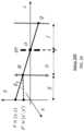
- FIG. 3 illustrates a typical example of modulation or phase maps 300 with two defects, a scratch (A) and a pit (B).
- Maps 300 may be part of an AVI system that includes AVI devices, systems, configurations and methods described herein.
- a small defect appears as a dent, bump, or a line.
- the map values in the defect neighborhood 310 are different than the map values at the defect locations 312 of scratch A and 314 of pit B.
- a visibility V of a defect is defined as
- H and h are the maximum and the minimum values of the map in the defect's neighborhood (see FIG. 3 right side). Profiles of the map along the x and y directions produce the curves depicted at the right in FIG. 3 .
- the horizontal section crosses through the two defects, and we can see the rapid variation of the phase/modulation maps on the defects. Values H and h are the maximum and minimum values of the observed quantity (either modulation or phase) in the neighborhood of the defect.
- a neighborhood or inspection area is an area inspected by an AVI system and/or method over a period of time before the system moves to another area or neighborhood of the lens.
- neighborhood 310 has a lateral extension of between 60 mm and 70 mm. In some cases, it is between 10 mm and 100 mm. It may also be the entire size of the lens.
- defect A or B has a lateral extension 312 or 314 of between 0.001 mm and 0.1 mm. In some cases, the area is 10 ⁇ that much. It may also be a lateral extension between 0.001 mm and 2 mm.
- the defect length or area is 1/100 the size of the neighborhood. It may also be 1/1,000 the size. It may be 1/10,000 the size.
- Visibility is important to defect detections. Visibility is used to quantify a defect's importance.
- FIG. 4 illustrates a schematic 400 of how a prismatic defect produces an angular deviation of the ray that passes through it in a phase measuring deflectometry configuration.
- the schematic 400 may be part of an AVI system that includes AVI devices, systems, configurations and methods described herein.
- a prismatic defect generates deflection and has a transmittance close to 1, T(M) ⁇ 1 in equation (2).
- a prismatic defect represented by the vertical arrow with a circle end, located at point M of the surface under inspection.
- point P on the screen will image at point Q of the camera plane though the principal ray PMOQ that intersects the surface at point M.
- the ray PMOQ transforms into ray P′MOQ by a deflection at point M of the surface. Physically this defect can be interpreted as a local variation in the surface slope.
- V ⁇ ⁇ ⁇ 1 for ⁇ ⁇ S >> ⁇ 0 for ⁇ ⁇ S ⁇ ⁇ ⁇ ⁇ and ( 7 ) V m ⁇ 0 ⁇ ⁇ for ⁇ ⁇ any ⁇ ⁇ S ( 8 )
- S the visibility of the prismatic defect on the phase and modulation maps is small, such that V ⁇ ⁇ 0 and V m ⁇ 0.
- S the visibility of a defect in the phase map will be significant, V ⁇ ⁇ 1; meanwhile for the modulation, the visibility is small such that V m ⁇ 0.
- this behavior is shown graphically.
- FIGS. 5 A and 5 B show phase and modulation maps 500 and 550 , respectively, at a neighborhood of image point Q of FIG. 4 for a prismatic defect.
- the phase ⁇ y corresponds to the solid line and the modulation m is represented by the dashed line.
- the fringe period is small, p «, and the sensitivity high S».
- FIG. 5 B shows the same maps but using a big fringe period p» and low sensitivity S «.
- FIG. 6 illustrates a schematic 600 of how a lenslet defect integrates light coming from all points between P 1 and P 2 in a small area centered in image point Q in a phase measuring deflectometry configuration.
- the schematic 600 may be part of an AVI system that includes AVI devices, systems, configurations and methods described herein.
- a lenslet defect behaves like a small thin lens and has a transmittance close to 1, T(M) ⁇ 1.
- T(M) ⁇ 1 For this defect, the net effect is the integration of light coming from different directions into a small area centered in the same image point. In the image plane, the pixel size and the amount of defocus will determine this area around the image point.
- FIG. 6 depicts a lenslet defect, represented by the dark-grey double-arrow, located at point M of the surface under inspection.
- V ⁇ ⁇ 0 ⁇ ⁇ for ⁇ ⁇ any ⁇ ⁇ S ⁇ ⁇ and ( 9 ) V m ⁇ ⁇ 1 for ⁇ ⁇ S >> ⁇ 0 for ⁇ ⁇ S ⁇ ⁇ ( 10 )
- S the visibility of the lenslet defect on the phase and modulation maps is small, such that V ⁇ ⁇ 0 and V m ⁇ 0.
- S the visibility of a defect in the modulation map will be significant, such that V m ⁇ 1; meanwhile for the phase, the visibility will be small, such that V ⁇ ⁇ 0.
- FIG. 7 show this behavior graphically.
- FIGS. 7 A and 7 B show phase and modulation maps 700 and 750 , respectively, at a neighborhood of image point Q of FIG. 6 for a lenslet defect.
- the phase ⁇ y corresponds to the solid line, and the modulation m is represented by the dashed line.
- the fringe period is small, p « and the sensitivity high S».
- 5 B shows the same maps but using big fringe period p» and low sensitivity S «.
- the visibility V m of a lenslet defect increases with the lateral size ⁇ y on the screen.
- ⁇ y depends on the maximum deflection ⁇ y and its area. Therefore, the visibility of a lenticular defect in the modulation map depends on its area. Defects with larger areas present bigger visibilities in the modulation map.
- the apparent brightness is an indicator used to classify a defect. From radiometric considerations, the apparent brightness of a defect observed in reflection increases with its area. Therefore, the apparent brightness and the visibility of the defect in the modulation map are related. This relation is significant.
- the system correlates the visibility of a defect in the modulation map with its luminous intensity when observed under reflection. Luminous intensity is a photometric quantity related with the perceived “brightness” of a small, point-like, source.
- FIG. 8 illustrates a schematic 800 of how a transmissive defect does not deflect the principal ray PMOQ but reduces the intensity reaching image point Q because locally the transmittance is smaller than in its surroundings in a phase measuring deflectometry configuration.
- the schematic 600 may be part of an AVI system that includes AVI devices, systems, configurations and methods described herein.
- a pure transmissive defect does not produce deflection and only changes the image intensity thought its transmittance T(M), see equation (2).
- FIG. 8 depicts a transmissive defect, represented by the vertical line with circle ends, located at point M of the plane surface under inspection. The effect of this type of defect is to reduce the intensity reaching point Q by a reduction in the local transmittance.
- this defect can be interpreted as dust or opaque particles on the lens surfaces.
- This defect does not deflect the principal ray PMOQ but reduces the intensity reaching image point Q because locally the transmittance is smaller than in its surroundings.
- T(M) for these type of defects T(M) ⁇ 1.
- FIGS. 9 A and 9 B show phase and modulation maps 900 and 950 , respectively, at image point Q of FIG. 8 for a transmissive defect.
- the phase ⁇ y corresponds to the solid line, and the modulation m is represented by the dashed line.
- the fringe period is small, such that p «, and the sensitivity is high, such that S».
- FIG. 9 B shows the same maps using a big fringe period p» and low sensitivity S «.
- V ⁇ ⁇ 0 for any S (11)
- the visibility of the transmissive defect on the modulation map is V m ⁇ 1 for any S (12)
- FIGS. 9 A and 9 B show this behavior graphically.
- Table 1 is a summary of the expected visibility values in the phase and modulation maps for the different types of defects and sensitivities discussed in the main text.
- the visibility in the phase and modulation maps for the different types of defects are shown as a function of the sensitivity of transmissive defects with low transmittance.
- Set A has small sensitivity and a long fringe period.
- Set B has high sensitivity and a short fringe period.
- Cosmetic defects typically behave like prism or lenslet defects. On the other hand, dust and particles on the surface behave like transmissive defects. Based on their different behavior on phase and/or modulation maps, it is possible to differentiate between actual cosmetic defects and dust/particles. Cosmetic defects may be differentiated from dust using two sets of fringe patterns, set A and set B. For the set A, a fringe pattern with a high spatial period is used. For this set, dust and dirt (transmissive defects) have excellent visibility on the modulation map (see the first row of Table 1, above). In contrast, the other defect types are not visible either in the modulation or phase maps. Therefore, the system can designate those areas appearing using set A as dust or particles on the surface. These defects can be ignored by the system and the system will not invalidate a semifinished or finished lens on this basis.
- Set B has a small fringe period.
- prismatic defects appear with high visibility in the phase map instead of the modulation map.
- all defects that arise using set B and that were not previously marked as dust are classified as cosmetic defects.
- These defects can be used as a basis for invalidating a semifinished or finished lens. For example, one of these defects on the front surface but not on the back surface can be ignored and not be a basis for invalidating a semifinished lens. However, one of these defects on the front or the back surface can be a basis for invalidating a finished lens.
- a defect on the back surface of a semifinished lens will be removed after surfacing, but if it is located on the front surface, it may be invalidating. For example, if a defect on the front surface is not permissible using a visual inspection standard, it will cause the finished or a semifinished lens to be invalidated. If a defect on the back surface is not permissible using a visual inspection standard, it may cause a finished lens to be invalidated, but it will have no importance for a semifinished lens.
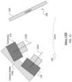
- FIG. 10 shows a phase measuring deflectometry configuration 1000 to determine if a defect is located on a front surface or a back surface of a lens using two cameras represented by the optical centers O 1 and O 2 and their respective entrance pupils, EP.
- Configuration 1000 may be part of an AVI system that includes AVI devices, systems, configurations and methods described herein.
- This embodiment captures images from two or more positions—points of view, optical centers, camera/lens poses or gazes—using two or more fixed cameras, or a single camera working on a movable camera holder to reposition the camera to the locations shown.
- points B and F represent two defects located on the back and front sides of the lens, respectively.
- Point B images on camera 1 and 2 as points P 1 and P 2 respectively.
- Points Q 1 and Q 2 are the images of point F on cameras 1 and 2 .
- the cameras are calibrated so that the spatial position of point B with respect to O 1 can be calculated from the intersection of rays O 1 P 1 and O 2 P 2 .
- the position of its image is as observed through the lens.
- Point F can be triangulated also from rays O 1 Q 1 and O 2 Q 2 .
- the spatial position from the geometry shown in FIG. 10 is used to determine if that defect is in the front or the back side of the lens by measuring its distance to the calibrated arbitrary surface E.
- the calibrated surface E is usually selected close to the lens frontal vertex.
- the discrimination between frontal and frontal defects can be determined based on whether the normal distance of a defect position to the calibrated surface is close (for a frontal defect) or farther than a threshold distance (for a back side defect).
- Configuration 1000 may be described as frontal/back side discrimination from triangulation.
- the triangulation of a defect location it is necessary to perform the calibration of the intrinsic parameters for both cameras and the extrinsic parameters between the cameras.
- Intrinsic parameters may include the focal distance, principal point and skew factor.
- the extrinsic parameters may describe the roto-translation between the coordinate systems of both cameras.
- the triangulation method can be implemented using two or more cameras or one camera and two or more lens positions offering a different gaze each.
- a second strategy for front and back detection is referred to as the mapping method and does not need explicit camera calibration.
- the mapping method consists of the calculation of the mapping, H i ⁇ ⁇ that exists between each camera plane and a calibrated surface. For a plane surface, this mapping is a linear operator, a homography, but for a general reference surface, it is a non-linear mapping.
- FIG. 11 shows a phase measuring deflectometry configuration 1100 to determine if a defect is located on a front surface or a back surface of a lens using two cameras and a calibrated surface ⁇ . The two cameras are represented by the optical centers O 1 and O 2 ; and their respective entrance pupils, EP.
- Configuration 1100 may be part of an AVI system that includes AVI devices, systems, configurations and methods described herein. This embodiment captures images from two or more positions—points of view, camera centers, camera/lens poses or gazes—using two or more fixed cameras, or a single camera working on a movable camera holder to reposition the camera to the locations shown.
- the calibrated surface, ⁇ is a plane. Points ⁇ Q 1 ,Q 2 ⁇ and ⁇ P 1 ,P 2 ⁇ are the images of points B and F on cameras 1 and 2 respectively.
- Configuration 1100 may be described as frontal/back side discrimination measuring disparity.
- the second strategy may be a front/back defect location from the defect disparity as seen from the at least two points of view.
- the mapping method can be implemented using two or more cameras; or one camera and two or more lens orientations, each lens orientation offering a different camera pose (lens gaze or point of view).
- two different points of view, optical centers, camera/lens poses or gazes can be created by two cameras at two camera orientations with respect to a single lens orientation; by one camera moved to two orientations with respect to a single lens orientation; or by a single camera at one orientation with respect to a lens moved to two orientations with respect to the camera.
- a point of view or camera pose can be determined by the positions of the camera optical center and the orientations of the camera axis. It can also be determined by the distance of the optical center from and orientation of the axis with respect to the front surface of the lens.
- Embodiments of an AVI system use the defect classification methods and/or systems discussed above, including the distinction between dust and cosmetic defects and the localization of the defect in the back or frontal sides of the lens and estimation of the defect luminous intensity and area.
- the embodiments of the AVI system include a screen for generating fringe patterns, a lens holder and a camera or set of cameras.
- the screen is a display, either static having a single fringe pattern or dynamic having several fringe patterns, that emits natural or polarized light.
- the screen can be a passive diffusive screen on which fringe patterns are projected from either side of the screen.
- the cameras are capable of capturing radiometric information. That is, they are sensitive to input irradiance. Alternatively, or additionally, the cameras are capable of capturing polarimetric information. That is, they are sensitive to the input irradiance and the polarization state of the light.
- System 1200 may be an embodiment of an AVI system that includes AVI devices, systems, configurations and methods described herein.
- the system captures images from two or more positions 1210 and 1220 using two or more fixed cameras, or a single camera working on a movable camera holder 1240 (optional) to reposition the camera to the locations shown.
- Positions 1210 and 1220 represent two points of view, optical centers, different camera/lens poses or gazes.
- the system captures the images shown on the screen 104 in transmission through the lens.
- the system embodiment depicted in FIG. 12 has two cameras 110 (or a single camera shown in two positions).
- FIG. 13 shows a configuration of an AVI system 1300 having a stand-alone reflection deflectometry configuration using two or more cameras 110 with the lens 102 in a static position.
- System 1300 may be an embodiment of an AVI system that includes AVI devices, systems, configurations and methods described herein.
- the system captures images from two or more positions 1310 and 1320 using two or more fixed cameras, or a single camera working on a movable camera holder 1340 (optional) to reposition the single camera to the locations shown.
- Positions 1310 and 1320 represent two points of view, optical centers, different camera/lens poses or gazes.
- the system captures the images shown on the screen 104 after reflection on both surfaces of the lens.
- the system embodiment depicted in FIG. 13 has two cameras 110 (or a single camera shown in two positions).
- FIG. 14 shows a configuration of an AVI system 1400 having a stand-alone transmission deflectometry configuration using a movable lens holder 1405 and a single camera 110 .
- System 1400 may be an embodiment of an AVI system that includes AVI devices, systems, configurations and methods described herein.
- the movable lens holder 1405 places the lens in two or more positions that permit the observation of the lens under different views 1410 and 1420 as shown. Views 1410 and 1420 represent two points of view, optical centers, different camera/lens poses, positions or gazes.
- the images shown on the screen 104 are captured in transmission through the lens.
- the system embodiment depicted in FIG. 14 has two lens orientations.
- FIG. 15 shows a configuration of an AVI system 1500 having a stand-alone reflection deflectometry configuration using a movable lens holder 1505 and a single camera 110 .
- System 1500 may be an embodiment of an AVI system that includes AVI devices, systems, configurations and methods described herein.
- the movable lens holder 1505 places the lens in two or more positions that permit the system to observe the lens under different views 1510 and 1520 as shown. Views 1510 and 1520 represent two points of view, optical centers, different camera/lens poses, positions or gazes.
- the system captures images shown on the screen 104 after reflection on both surfaces of the lens.
- the system embodiment depicted in FIG. 14 has two lens orientations.
- FIG. 16 is a block diagram 1600 of a lens production line having at least two processing steps (a photochromic coating of the frontal surface and surfacing of the back surface), three AVI systems, and one central control unit (CCU).
- Diagram 1600 depicts an embodiment of an AVI system that includes AVI devices, systems, configurations and methods described herein.
- Diagram 1600 uses the three AVI systems—AVI # 1 , AVI # 2 and AVI # 3 —in a photochromic lens production line, to perform quality control inspection of cosmetic defects at three stages.
- the process starts with a semifinished blank, a standard semi-finished lens which is the substrate for coating.
- the coating is photochromic. Instead, it can be a hard coating, an anti-reflective coating, or another known coating for a lens.
- a semifinished blank is provided to/received by to AVI # 1 which performs a total quality control or an acceptance quality limit (AQL) analysis according to a visual inspection standard for surface defects in the frontal surface before being sent to the coating step.
- AQL can be defined as the “quality level that is the worst tolerable” in ISO 2859-1. It represents the maximum number of defective units, beyond which a batch is rejected. Manufacturers may set different AQLs for critical, major, and minor defects. For example, “AQL is 1.5%” means “no more than 1.5% defective items” are permissible, which may be based on a whole order quantity, an average over several production runs, etc.
- the manufactured photochromic semifinished lenses are inspected by an AVI # 2 for defects in the frontal coated surface.
- the photochromic semifinished lenses are put through a final AQL analysis of cosmetic defects in the frontal side by AVI # 3 .
- any defects on the front side of the lens is made.
- a large cosmetic defect on the front surface that is close to the edge has little importance because of the final edging that is performed later in processing to fit the finished lens to the frame.
- a small cosmetic defect at the center of the front surface can invalidate a semifinished lens because that defect will remain after the final edging.
- the system also differentiates between actual cosmetic defects and dust/dirt particles on the surface.
- Optical laboratories are industrial production environments where dust/dirt can appear quickly on the lens surface, and therefore, it is not uncommon that lenses have some dust on them. That is, the system cannot rely on having dust-free lenses for the AVI process.
- the AVI systems can be placed at different locations of a lens production line and can be connected to a central control unit (CCU) for data aggregation and processing.
- the AVI # 1 system can make a total quality control or an AQL of the input semifinished lenses, looking for frontal surface defects, but only those that affect the coating process (see below).
- the AVI # 2 system may perform total quality control of the coating process, identifying cosmetic defects at the front surface of coated blanks.
- the AVI # 3 system can make a total quality control or an AQL of the finished or near-finished lenses looking for invalidating cosmetic defects on any side of the lens. Additionally, the AVI # 3 system can map the finished lens and perform quality control of the lens power.
- the different AVI systems may use a different visual inspection standard.
- the CCU may adapt the visual inspection standard of one particular AVI system.
- the connections between the AVIs and the CCU are shown as a two-headed arrow such that information flows in both directions.
- data received by the CCU from AVI # 2 can allow for the learning of those defects on the frontal surface detected by the AVI # 1 that remain after the coating.
- the CCU can adapt the AVI # 1 visual inspection standard to focus the detection in only those types of frontal defects that do not disappear in the coating process.
- 16 is a possible embodiment of the use of multiple AVI systems coordinated through a CCU using different visual inspection standards. It may represent a physical setup where all the units are located and wired at the same place and work at the same time. It may represent a logical setup where coating is done one day in one country or city; surfacing is done two days later in another country or city; and the CCU is located in a third country or city. It may be expanded to cover any generalization of this embodiment with N steps and M AVIs.
- the AVI # 2 and # 3 systems allow for the monitoring of the coating and surfacing processes. If the quality falls below a specific limit, the line can be stopped for maintenance. Also, quality trends and other manufacturing issues identified by the CCU can be used for programming maintenance stops of the production line.
- a skilled inspector optionally supervises the classification results of an AVI system providing data to the CCU, allowing the CCU to learn the inspectors unwritten, implicit criteria for the assessment of the cosmetic quality of lenses. In this way, the AVI system 1600 of FIG.
- 16 allows for: defect monitorization along the production line for assessing the impact on the final product; the use of adaptive visual inspection standards along the production line using statistical and machine learning techniques; modeling and characterization of the production line using statistical and machine learning techniques for stability and cleanliness of the manufacturing line, quality stability for input the lenses, quality stability of the manufacturing process, determination of causes for the generation of defects and its correction.
- FIG. 17 is a flow diagram of an operating environment/process 1700 for automatic visual inspection of cosmetic defects in a transmissive lens, such as ophthalmic lens and optical elements.
- the process 1700 may be performed by the any of the AVI systems described herein.
- the process 1700 may be part of or include any of the AVI methods described herein.
- the process 1700 starts at 1705 and can end at 1740 , but the process can also be cyclical and return to 1705 after 1740 .
- the process may return to 1705 for re-inspection of a lens after cleaning dust or dirt off that was detected during inspection. It can also return to inspect another lens after inspection of a first lens.
- Process 1700 may be based on using measured fringe phase values and/or fringe modulation values, instead of the direct image for the estimation of the relative luminous intensity of a defect.
- the process 1700 starts at 1705 which is using a plurality of camera poses to provide deflectometric measurements from at least two points of view of the lens for at least one oriented fringe pattern of dark and bright bars.
- the dark bars and bright bars have equal lateral thickness.
- the bars are arranged in a sinusoidal fringe pattern.
- various other oriented fringe patterns of dark and bright bars can be used.
- Using a plurality of camera poses at 1705 may include observing the screen through the lens for at least two points of view and a screen that is displaying the fringe pattern.
- Using a plurality of camera poses at 1705 may include observing the lens to provide deflectometric measurements from or of the lens as described herein. Using a plurality of camera poses at 1705 may include imaging the lens to use the fringe (dark and bright bars) phase and the fringe modulation for defect location.
- the process moves to 1710 which is measuring phase visibility values and/or modulation visibility values of the deflectometric measurements for at least two different sensitivities of a deflectometric setup using at least one fringe pattern taken through an inspection area of the lens from the at least two points of view.
- Measuring at 1710 may include creating phase visibility value maps and/or modulation visibility value maps of the deflectometric measurements for a front and a back surface of the lens from the at least two points of view.
- Measuring at 1710 may include measuring phase visibility values and/or modulation visibility values of the deflectometric measurements from or of a lens as described herein.
- the measuring includes measuring the values of the deflectometric measurements for at least two different sensitivities of a deflectometric setup using at least one set of oriented fringe patterns of dark and bright stripes having different spatial periods that are displayed on a screen plane; and generating (i.e., calculating and showing) a map of the measured phase visibility values and a map of the measured modulation visibility values.
- This measuring may include obtaining images from two or more points of view to measure fringe phase values and fringe modulation values of the images, instead of the direct image for the estimation of the relative luminous intensity of a defect during detecting a defect at 1720 .
- the measuring includes measuring the values of the deflectometric measurements for at least two different sensitivities of a deflectometric setup using two sets of orthogonal (e.g., transverse, tangentially or right angle) x,y oriented fringe patterns of dark and bright stripes having different spatial periods; and the map so for the two sets of orthogonal x,y oriented fringe patterns.
- orthogonal e.g., transverse, tangentially or right angle
- the process moves to 1720 which is detecting a defect of the lens at a defect location in the inspection area based on the phase visibility values and/or modulation visibility values at a defect location.
- Detecting at 1720 may include detecting a defect on one of the front surface or the back surface of the lens at a defect location in the inspection area based on the phase visibility values and/or modulation visibility values at the defect location as compared to the values of the inspection area.
- the inspection area may be a local neighborhood area immediately adjacent to and surrounding the defect location.
- Detecting at 1720 may include detecting relative luminous intensity of a defect in phase visibility value maps and/or modulation visibility value maps of the deflectometric measurements of a front and a back surface of the lens from the at least two points of view. Detecting at 1720 may include detecting defects using phase visibility values and/or modulation visibility values of the deflectometric measurements from or of a lens as described herein. In some cases, the detecting includes estimating a defect luminous intensity and a defect area of the defect based on the phase map and/or the modulation map; and classifying whether the defect is dust/dirt or cosmetic/functional defect based on the defect type, the defect luminous intensity, the defect area and its relative position.
- Classifying at 1730 is classifying whether a defect type of the defect is a transmissive defect, a lenslet defect or a cosmetic defect based on the phase visibility values and/or modulation visibility values.
- Classifying at 1730 may include classifying a defect type based on the two sets of values at the defect location as compared to the values of a local neighborhood area and based on the visual inspection standard.
- Classifying at 1730 may include classifying using relative luminous intensity of a defect in phase visibility value maps and/or modulation visibility value maps of the deflectometric measurements of a front and a back surface of the lens from the at least two points of view.
- Classifying at 1730 may include classifying defect types using phase visibility values and/or modulation visibility values of the deflectometric measurements from or of a lens as described herein. In some cases, classifying at 1730 may include also classifying the defect as a cosmetic or functional defect depending on a visual inspection standard.
- the classifying includes differentiating whether the defect type is a transmissive defect (dust), a deflective (prismatic) defect or a lenslet (functional/cosmetic) defect using the phase map and/or the modulation map.
- the classifying may also include determining a ratio of whether the defect type has a transmissive, deflective/prismatic, or lenslet character of the detected defect using the phase map and the modulation map.
- the system can calculate the ratio transmissive vs prismatic vs defective for given characteristics of the defect.
- the classifying includes determining the depth of the defect within a body of the lens; and deciding whether the defect is located on the front surface or on the back surface of the lens based on the phase visibility values and/or modulation visibility values from the at least two points of view and a geometry of the lens orientation to the two points of view.
- the classifying includes using setups and fringe patterns with different sensitivities of a deflectometric setup that have a high sensitivity S>20 ⁇ and a low sensitivity S ⁇ that result in a high and a low sensitivity phase map and modulation map. Then, based on these maps, classifying the defect type is:
- Localizing at 1735 may include localizing based on the phase visibility values and/or modulation visibility values from the at least two points of view and a geometry of the lens orientation to the two points of view. Localizing at 1735 may include localizing defects using phase visibility values and/or modulation visibility values of the deflectometric measurements from or of a lens as described herein.
- the localizing includes at least two points of view using two camera poses, estimating a defect luminous intensity of the defect based on the fringe modulation deflectometric measurements, creating a phase map of fringe phase deflectometric measurements from the at least two points of view and creating a modulation map of fringe modulation deflectometric measurements from the at least two points of view. Then, localizing the defect on the front or back surface based on the phase map and the modulation map.
- the localizing is based on discriminating that the defect location is on the front or back surface from the defect disparity as seen from the at least two points of view. It may also or alternatively be based on discriminating that the defect location is on the front or back surface from a triangulation of the defect position as seen from the at least two points of view (e.g., different camera/lens poses or a different gaze of each camera or point of view).
- the process moves to 1740 which is invalidating the lens based on whether the defect is a cosmetic defect type, the defects number and relative position (clusters), its location in the inspection area, its size, its brightness and based on whether the defect is located on the front or the back surface of the lenses.
- the numbers of defects, locations, sizes and/or brightness that distinguish the defect type are considered. These examples may be based on or may be part of various visual inspection standards. For example, a 75 mm diameter semifinished lens can be divided in three zones 1 , 2 and 3 .
- Zone 1 is the 30 mm diameter central disk
- zone 2 is the annular region between diameters 30 and 66 mm
- zone 3 is the annular region between diameter 66 mm and the lens border at 75 mm.
- a lens is considered correct if the front surface has less than 4 cosmetic defects smaller than 0.1 mm with a brightness bellow 0.5 in zone 1 and less than 4 cosmetic defects smaller than 0.2 mm and a brightness bellow 0.5 in zone 2 .
- Brightness can be defined in terms of the normalized modulation between 0 and 1 in arbitrary units. There can be any number of defects smaller than 0.05 mm in zones 1 and 2 unless clustered. A cluster can be defined as two defects that are closer than 5 mm.
- Invalidating at 1740 may include invalidating a lens based on phase visibility values and/or modulation visibility values of the deflectometric measurements from or of a lens as described herein. In some cases, the invalidating at 1740 includes invalidating a lens if the AVI system detects a defect that is:
- the invalidating at 1740 includes invalidating a lens if the AVI system detects a defect that is:
- the invalidating includes an invalidating system having a defect warning having a light, a sound, a display message and/or a network message transmission indicating: detection of the defect, identification of the defect type of the defect and the surface the defect is on, and identification of which lens has the defect.
- a calibration process of the AVI system is performed prior to using a plurality of camera poses at 1705 .
- the process may include using the system without the lens or removing the lens from the at least two points of view. Without the lens the system is used to measure the phase visibility values and/or modulation visibility values of the deflectometric measurements for the different sensitivities from the at least two points of view.
- determining the phase visibility values and/or modulation visibility values taken with the lens includes using the measured phase visibility values and/or modulation visibility values taken without the lens. That is, the phase visibility values and modulation visibility values without the lens can be used to obtain values for calculating sensitivities and modulation base values for the AVI system that are used to calculate the phase visibility values and modulation visibility values taken with the lens.
- FIG. 18 is a block diagram of an AVI system 1800 for automatic visual inspection of cosmetic defects in a transmissive lens, such as ophthalmic lens or an optical element.
- the system 1800 may perform process 1700 or any other AVI inspection process described herein.
- the system 1800 may include, be, or be part of any of the AVI devices, systems, configurations and methods described herein.
- the system 1800 includes one or more camera(s) 1810 for providing points of view and receiving images as noted herein. Camera(s) 1810 may be one or more cameras such as camera 110 or otherwise as noted herein.
- the system 1800 includes camera holder 1840 to position and/or move a camera as noted herein. Camera holder 1840 may be a camera holder as noted herein.
- the system 1800 includes camera interface 1820 for controlling camera(s) 1810 for providing points of view and images as noted herein and/or camera holder 1840 to be used as noted herein.
- the system 1800 includes lens holder 1805 to position and/or move a lens with respect to camera(s) 1810 and screen 1804 as noted herein.
- Lens holder 1805 may be a lens holder as noted herein.
- the system 1800 includes lens holder controller 1822 for controlling lens holder 1805 for controlling positioning and/or moving of a lens with respect to camera(s) 1810 and screen 1804 as noted herein.
- the system 1800 includes screen 1804 for providing one or more fringe patterns to be imaged by camera(s) 1810 as noted herein.
- Screen 1804 may be a screen such as screen 104 or otherwise as noted herein.
- the system 1800 includes screen controller 1822 for controlling screen 1804 to provide one or more fringe patterns to be imaged by camera(s) 1810 as noted herein.
- System 1800 also has central control unit (CCU) 1850 for controlling interface 1820 , controller 1822 and/or controller 1824 .
- CCU 1850 also performs other control and processing based on images from the camera(s) and information received form interface 1820 , controller 1822 and/or controller 1824 .
- CCU 1850 includes orienting unit 1852 which is configured to perform orienting of a lens to provide deflectometric measurements 1705 shown in and described regarding FIG. 17 .
- the orienting 1705 may include control or movement of camera(s) 1810 using interface 1820 ; control or movement of lens holder 1805 using controller 1822 ; and/or control or movement of screen 1804 using controller 1824 .
- the orienting 1705 may include receiving or be based on data from calibration unit 1866 .
- CCU 1850 also includes measuring unit 1854 which is configured to perform measuring of phase and/or modulation visibility values 1710 shown in and described regarding FIG. 17 .
- the measuring 1710 may include focus of, activation of and receiving images from camera(s) 1810 using interface 1820 ; moving lens holder 1805 using controller 1822 ; and/or control of and displaying fringe patterns on screen 1804 using controller 1824 .
- the measuring 1710 may include receiving or be based on orientation data received from orientation unit 1852 .
- CCU 1850 includes detecting unit 1856 configured to perform detecting of a defect 1720 shown in and described regarding FIG. 17 .
- the detecting 1720 may include receiving or be based on phase and/or modulation visibility values received from measurement unit 1854 . It may also include receiving or be based on orientation data received from orientation unit 1852 .
- CCU 1850 includes classifying unit 1860 which is configured to perform classifying of a defect type 1730 shown in and described regarding FIG. 17 .
- the classifying 1730 may include receiving or be based on phase and/or modulation visibility values received from measurement unit 1854 and/or from detecting unit 1856 .
- the CCU 1850 also includes localizing unit 1862 which is configured to perform localizing of a defect surface 1735 shown in and described regarding FIG. 17 .
- the localizing 1735 may include receiving or be based on phase and/or modulation visibility values received from measurement unit 1854 and/or from detecting unit 1856 .
- the localizing 1735 may include receiving or be based on a geometries, planes and/or distances: a) of the of camera(s) 1810 received from interface 1820 ; b) of lens holder 1805 received from controller 1822 ; and/or c) of screen 1804 received from controller 1824 .
- the geometry, planes and distances may include those referred to in FIGS. 11 and 12 .
- CCU 1850 includes invalidating unit 1864 which is configured to perform invalidating of a lens 1740 shown in and described regarding FIG. 17 .
- the invalidating 1740 may include receiving or be based on a defect type and surface of the defect received from classifying unit 1860 and from localizing unit 1862 .
- the invalidating 1740 may include receiving or be based on a visual inspection standard and/or phase and/or modulation visibility values received from measurement unit 1854 and/or from detecting unit 1856 .
- CCU 1850 includes calibration unit 1866 which is configured to perform calibrating of cameras as noted for process 1700 .
- the calibration may include receiving or be based on orientation data received from orientation unit 1852 . It may also include receiving or be based on phase and/or modulation visibility values received from measurement unit 1854 .
- the AVI systems and/or methods described herein are suitable for inspecting various types of optical elements like ophthalmic lenses.
- This includes spectacle lenses, contact lenses, intraocular lenses, lenses for goggles, insert lenses, and other lenses for face shields, respirators, helmets, eye shields and other face-mounted gear. They may also be used to inspect contact lenses and intraocular lenses.
- the lens is optional.
- the descriptions herein may apply to an AVI method, system, configuration, kit or production line product that can be purchased and configuration to inspect lenses as described herein.
- Benefits of the AVI systems and/or methods described herein include reducing the number of skilled operators needed for manning the inspection processes. Inspection time is reduced, and inspection consistency will be increased.
- the AVI system makes possible the real-time statistical modeling of the production line. Installed AVI systems may also be easily updated to add new quality standards and features. For end users, the AVI system complements products and services that are offered to the optical industry, such as to implement a click-fee ophthalmic lens production line model.
- the AVI systems and/or methods described herein permit the quality control of semifinished lenses with or without extra layers, caps, coatings, or whatever structure used to control or modify the semifinished lens properties.
- Some advantages of the defect inspection of the AVI system include:
- the quality control can be total or an AQL analysis for checking the manufactured batches before sending the product to the final customer.
- the lens is already surfaced and finished from a semifinished blank.
- the product can contain extra layers, caps, coatings, or whatever structure used to control or modify the lens properties.
- the quality control can be total or realized as an AQL analysis for checking manufactured batches.
- main advantages are the same that of purpose No 1 above (Implementation of any explicit, written visual inspection standard or defect grading standard used for the assessment of the cosmetic quality of a lens) with the exception that the defect location if the front or backside of the lens is irrelevant for finished lenses.
- Another benefit of the systems and/or methods described herein is quality control of lens power. Additional to the detection of cosmetic defects, the AVI system described can be used as a lens mapper, adding an extra feature to the system.
- FIG. 19 is a block diagram of a computing device 1900 .
- the computing device 1900 may be representative of any of the components of an AVI system or method herein (such as part of any of AVI systems 100 , 150 , 1000 - 1600 and/or method 1700 ).
- Device 1900 may be the CCU of diagram 1600 or CCU 1850 .
- Device 1900 may be a specialized computing device that is part of an AVI system and/or method as noted herein. It may control other components of the system and/or method.
- the computing device 1900 may be a desktop or laptop computer, a server computer, a computer workstation, or other computer.
- the computing device 1900 includes software and/or hardware for providing functionality and features described herein. These computing devices may run an operating system, including variations of the Linux, Microsoft Windows, and Apple Mac operating systems.
- the techniques may be implemented with machine readable storage media in a storage device included with or otherwise coupled or attached to a computing device.
- the computing device 1900 may include one or more of logic arrays, memories, analog circuits, digital circuits, software, firmware and processors.
- the hardware and firmware components of the computing device 1900 may include various specialized units, circuits, software and interfaces for providing the functionality and features described herein.
- device 1900 may perform control and processing of an AVI system or method herein. This includes invalidating a lens as noted herein, such as at invalidating 1740 or unit 1864 .
- the computing device 1900 has a processor 1910 coupled to a memory 1912 , storage 1914 , a network interface 1916 and an I/O interface 1918 .
- the processor 1910 may be or include one or more microprocessors, field programmable gate arrays (FPGAs), application specific integrated circuits (ASICs), programmable logic devices (PLDs) and programmable logic arrays (PLAs).
- the memory 1912 may be or include RAM, ROM, DRAM, SRAM and MRAM, and may include firmware, such as static data or fixed instructions, BIOS, system functions, configuration data, and other routines used during the operation of the computing device 1900 and processor 1910 .
- the memory 1912 also provides a storage area for data and instructions associated with applications and data handled by the processor 1910 , such as data and instructions associated with the control and processing of an AVI system or method herein.
- the term “memory” corresponds to the memory 1912 and explicitly excludes transitory media such as signals or waveforms.
- the storage 1914 provides non-volatile, bulk or long-term storage of data or instructions in the computing device 1900 , such as data and instructions associated with the control and processing of an AVI system or method herein.
- the storage 1914 may take the form of a magnetic or solid state disk, tape, CD, DVD, or other reasonably high capacity addressable or serial storage medium. Multiple storage devices may be provided or available to the computing device 1900 . Some of these storage devices may be external to the computing device 1900 , such as network storage or cloud-based storage.
- the terms “storage” and “storage medium” correspond to the storage 1914 and explicitly exclude transitory media such as signals or waveforms. In some cases, such as those involving solid state memory devices, the memory 1912 and storage 1914 may be a single device.
- the memory 1912 and/or storage 1914 can include an operating system executing the data and instructions associated with the control and processing of an AVI system or method herein.
- the network interface 1916 includes an interface to a network such as a network that can be used to communicate network packets, network messages, telephone calls, faxes, signals, streams, arrays, and data and instructions associated with the control and processing of an AVI system or method herein.
- the network interface 1916 may be wired and/or wireless.
- the network interface 1916 may be or include Ethernet capability.
- the I/O interface 1918 interfaces the processor 1910 to peripherals (not shown) such as displays, video and still cameras, microphones, user input devices (for example, touchscreens, mice, keyboards and the like).
- peripherals not shown
- the I/O interface 1918 interface may support USB, Bluetooth and other peripheral connection technology.
- the I/O interface 1918 includes the peripherals, such as displays and user input devices, for user accessed to data and instructions associated with the control and processing of an AVI system or method herein to perform any of the actions noted in FIGS. 1 A- 18 .
- storage 1914 is a non-volatile machine-readable storage medium that includes computer readable media, including magnetic storage media, optical storage media, and solid state storage media.
- the software can be installed in and sold with an AVI system or method herein and/or the other published content or components of and AVI system or method.
- the software can be obtained and loaded into the data and instructions associated with the AVI system or method herein, including obtaining the software via a disc medium or from any manner of network or distribution system, including from a server owned by the software creator or not owned but used by the software creator.
- the software can be stored on a server for distribution locally via a LAN and/or WAN, and/or to another location via a WAN and/or over the Internet.
- Each of units 1852 - 1866 may be or include hardware circuitry, BIOS, ROM, an OS, computer instructions and/or a computing unit. These units may be hardware, software, firmware, or a combination thereof. Additional and fewer units, modules or other arrangement of software, hardware and data structures may be used to achieve the processes and apparatuses described herein.
- “plurality” means two or more. As used herein, a “set” of items may include one or more of such items.
- the terms “comprising”, “including”, “carrying”, “having”, “containing”, “involving”, and the like are to be understood to be open-ended, i.e., to mean including but not limited to. Only the transitional phrases “consisting of” and “consisting essentially of”, respectively, are closed or semi-closed transitional phrases with respect to claims.
Abstract
Description
-
- Automatically detect and classify relevant defects of a lens following a visual inspection standard or a defect grading standard like MIL-PRF-13830B, ANSI OP1.002 and ISO 10110-7;
- Automatically locate the defects and identify the front or back surface on which they sit;
- Automatically differentiate between actual defects and dust or dirt particles on the surfaces;
- Automatically classify a lens as good or bad in terms of a visual inspection standard or a defect grading standard;
- Implement and apply any explicit written visual inspection standard for lens classification;
- Implement and apply, as a machine learning process, the unwritten implicit criteria for the assessment of the cosmetic quality of a lens used by a skilled inspector;
- Ensure that the evaluation of a lens surface quality, in terms of visually permissible defects, is consistent throughout the lab network;
- In the case of assisted operation, prevent inspector fatigue; and/or
- Create a model lens production line with statistical or machine learning methods for:
- 1. Measuring trends in the cleanliness of the production line;
- 2. Measuring trends in the lens quality;
- 3. Measuring stability of the production line;
- 4. Determination of causes for the defects.
In
where b and m are the image background and modulation, respectively, y is the horizontal coordinate at the screen plane and p the fringe period.
where Z is the lens-screen distance, δy is the vertical deflection angle at point M=(ξ,η) and T(M) the transmittance of the lens at point M. Using demodulation techniques, from the 2-dimensional irradiance maps I(Q) and I′(Q) we can obtain a complex 2-dimensional x,y map defined on the image plane given by
is the sensitivity of the deflectometric setup, and mϕ represents the change in modulation due to the demodulation algorithm and the spatial sampling on the image plane.
ϕy=angle[A(Q)]=Sδ y (4)
and a 2-dimensional x,y modulation map
m=|A(Q)|=½m ϕ T(M) (5)
From herein we will denominate “2-dimensional x,y maps” simply as “maps”.
where H and h are the maximum and the minimum values of the map in the defect's neighborhood (see
For small sensitivities, S«, the visibility of the prismatic defect on the phase and modulation maps is small, such that Vϕ≈0 and Vm≈0. However, if the sensitivity is high, S», the visibility of a defect in the phase map will be significant, Vϕ≈1; meanwhile for the modulation, the visibility is small such that Vm≈0. In
For big sensitivities, S«, the visibility of the lenslet defect on the phase and modulation maps is small, such that Vϕ≈0 and Vm≈0. However, if the sensitivity is high, S», the visibility of a defect in the modulation map will be significant, such that Vm≈1; meanwhile for the phase, the visibility will be small, such that Vϕ≈0.
V ϕ≈0 for any S (11)
while the visibility of the transmissive defect on the modulation map is
V m≈1 for any S (12)
| TABLE 1 | |||
| Transmissive | Prismatic | Lenslet | |
| A) S<<; p>> | Vϕ ≈ 0; Vm ≈ 1 | Vϕ ≈ 0; Vm ≈ 0 | Vϕ ≈ 0; Vm ≈ 0 |
| B) S>>; p<< | Vϕ ≈ 0; Vm ≈ 1 | Vϕ ≈ 1; Vm ≈ 0 | Vϕ ≈ 0; Vm ≈ 1 |
-
- a. a prismatic defect type when at the defect location (“at the defect location” may describe “around” or “close to” the defect location. Strictly speaking the visibility change may not be “at” but “around”, or “with respect to the neighborhood” of the defect. It may also be at the inspection area):
- the high and low sensitivity modulation visibility maps show a change of 0,
- the high and low sensitivity phase visibility maps show a change of 1, and
- b. a lenslet defect type when at the defect location:
- the high and low sensitivity modulation visibility maps show a change of 1,
- the high and low sensitivity phase visibility maps show a change of 0; and
- c. a transmissive defect type when at the defect location:
- the high and low sensitivity modulation visibility maps show a change of 0,
- the high and low sensitivity phase visibility maps show a change of 0.
- a. a prismatic defect type when at the defect location (“at the defect location” may describe “around” or “close to” the defect location. Strictly speaking the visibility change may not be “at” but “around”, or “with respect to the neighborhood” of the defect. It may also be at the inspection area):
-
- A. a cosmetic defect type on the front surface of the semifinished lenses but not a defect that is a transmissive defect type on the front surface of the semifinished lenses and not a defect that is on the back surface of the semifinished lenses;
- B. a cosmetic defect type on the front surface of the coated blank lenses but not a defect that is a transmissive defect type on the front surface of the coated blank lenses and not a defect that is on the back surface of the coated blank lenses; or
- C. a cosmetic defect type on the front surface or the back surface of the ophthalmic finished lenses but not a defect that is a transmissive defect type on the front surface or the back surface of the ophthalmic finished lenses.
-
- A. a semifinished lenses having a defect on a frontal surface that is not permissible using first visual inspection standard that is a total quality control standard, or an Acceptance Quality Limit standard;
- B. a coated blank lens having a defect on a frontal surface that is not permissible using a second visual inspection standard that is a total quality control standard, or an Acceptance Quality Limit standard; or
- C. an ophthalmic finished lens having a defect on a frontal or a back surface that is not permissible using a third visual inspection standard that is a cosmetic defect detecting standard, a total quality control standard, or an Acceptance Quality Limit standard.
-
- 1) Implementation of any explicit, written visual inspection standard or defect grading standard used for the assessment of the cosmetic quality of a lens.
- 2) Automatic location of the defects on the back or front surfaces of the lens.
- 3) Automatically implement, as a machine learning process, the implicit, unwritten criteria used by a skilled inspector for assessment of the cosmetic quality of a lens.
- 4) Ensure that the evaluation of the lens surface quality, in terms of visually permissible defects, is consistent throughout the lab network.
- 5) In the case of assisted operation prevent inspector fatigue.
- 6) Model production characteristics with statistical or machine learning methods for:
- a. Measuring trends in the cleanliness of the production line
- b. Measuring trends in the lens quality
- c. Measuring stability of the production line
- d. Determination of causes for the defects
Claims (23)
Priority Applications (3)
| Application Number | Priority Date | Filing Date | Title |
|---|---|---|---|
| US17/028,429 US11650126B2 (en) | 2020-09-22 | 2020-09-22 | Systems and methods for automatic visual inspection of defects in ophthalmic lenses |
| PCT/US2021/050325 WO2022066474A1 (en) | 2020-09-22 | 2021-09-14 | Systems and methods for automatic visual inspection of defects in ophthalmic lenses |
| EP21873211.3A EP4217704A1 (en) | 2020-09-22 | 2021-09-14 | Systems and methods for automatic visual inspection of defects in ophthalmic lenses |
Applications Claiming Priority (1)
| Application Number | Priority Date | Filing Date | Title |
|---|---|---|---|
| US17/028,429 US11650126B2 (en) | 2020-09-22 | 2020-09-22 | Systems and methods for automatic visual inspection of defects in ophthalmic lenses |
Publications (2)
| Publication Number | Publication Date |
|---|---|
| US20220090983A1 US20220090983A1 (en) | 2022-03-24 |
| US11650126B2 true US11650126B2 (en) | 2023-05-16 |
Family
ID=80741465
Family Applications (1)
| Application Number | Title | Priority Date | Filing Date |
|---|---|---|---|
| US17/028,429 Active 2042-01-14 US11650126B2 (en) | 2020-09-22 | 2020-09-22 | Systems and methods for automatic visual inspection of defects in ophthalmic lenses |
Country Status (3)
| Country | Link |
|---|---|
| US (1) | US11650126B2 (en) |
| EP (1) | EP4217704A1 (en) |
| WO (1) | WO2022066474A1 (en) |
Families Citing this family (3)
| Publication number | Priority date | Publication date | Assignee | Title |
|---|---|---|---|---|
| US20230400714A1 (en) * | 2022-06-08 | 2023-12-14 | Johnson & Johnson Vision Care, Inc. | Methods for quality control of contact lenses |
| EP4343302A1 (en) * | 2022-09-26 | 2024-03-27 | Essilor International | Computer-implemented method for determining a localization of at least one defect in a tested ophthalmic lens |
| CN116433658B (en) * | 2023-06-08 | 2023-08-15 | 季华实验室 | Mirror-like defect detection method, device, electronic equipment and storage medium |
Citations (6)
| Publication number | Priority date | Publication date | Assignee | Title |
|---|---|---|---|---|
| US20020131052A1 (en) | 2000-11-13 | 2002-09-19 | Emery David G. | Advanced phase shift inspection method |
| US20040004693A1 (en) | 2002-02-21 | 2004-01-08 | Chrusch Peter Paul | Dual inspection of ophthalmic lenses |
| US7256881B2 (en) | 2002-02-15 | 2007-08-14 | Coopervision, Inc. | Systems and methods for inspection of ophthalmic lenses |
| WO2008125660A1 (en) | 2007-04-13 | 2008-10-23 | Essilor International (Compagnie Generale D'optique) | Method and apparatus for detecting defects in optical components |
| WO2011117539A1 (en) | 2010-03-23 | 2011-09-29 | Msc & Sgcc | Method and equipment for detecting the presence and extent of defects in an optical component |
| US10267750B2 (en) | 2017-02-09 | 2019-04-23 | Glasstech, Inc. | System and associated method for online detection of small defects on/in a glass sheet |
-
2020
- 2020-09-22 US US17/028,429 patent/US11650126B2/en active Active
-
2021
- 2021-09-14 EP EP21873211.3A patent/EP4217704A1/en active Pending
- 2021-09-14 WO PCT/US2021/050325 patent/WO2022066474A1/en unknown
Patent Citations (7)
| Publication number | Priority date | Publication date | Assignee | Title |
|---|---|---|---|---|
| US20020131052A1 (en) | 2000-11-13 | 2002-09-19 | Emery David G. | Advanced phase shift inspection method |
| US7256881B2 (en) | 2002-02-15 | 2007-08-14 | Coopervision, Inc. | Systems and methods for inspection of ophthalmic lenses |
| US20040004693A1 (en) | 2002-02-21 | 2004-01-08 | Chrusch Peter Paul | Dual inspection of ophthalmic lenses |
| WO2008125660A1 (en) | 2007-04-13 | 2008-10-23 | Essilor International (Compagnie Generale D'optique) | Method and apparatus for detecting defects in optical components |
| US8295581B2 (en) | 2007-04-13 | 2012-10-23 | Essilor International (Compagnie Generale D'optique) | Method and apparatus for detecting defects in optical components |
| WO2011117539A1 (en) | 2010-03-23 | 2011-09-29 | Msc & Sgcc | Method and equipment for detecting the presence and extent of defects in an optical component |
| US10267750B2 (en) | 2017-02-09 | 2019-04-23 | Glasstech, Inc. | System and associated method for online detection of small defects on/in a glass sheet |
Non-Patent Citations (9)
| Title |
|---|
| C. M. Cilip, D. S. Pratt, and M. B. Bauza, "Visual Inspection of Cosmetic and Functional Defects in a Manufacturing Environment." 2013. |
| D. Beghuin, X. Dubois, and L. Joannes, "Phase object power mapping and cosmetic defects enhancement by Fourier-based deflectometry," in Optical Measurement Systems for Industrial Inspection VI, 2009, doi: 10.1117/12.827670. |
| D. M. Aikens, "Objective measurement of scratch and dig," in Optics InfoBase Conference Papers, 2012, doi: 10.1364/oft.2012.otu2d.5. |
| F. Etzold, D. Kiefhaber, A. F. Warken, P. Würtz, J. Hon, and J.-M. Asfour, "A novel approach towards standardizing surface quality inspection," in Third European Seminar on Precision Optics Manufacturing, 2016, doi: 10.1117/12.2235743. |
| H.-D. Lin, W.-T. Lin, and H.-H. Tsai, "Automated Industrial Inspection of Optical Lenses Using Computer Vision," 2012. |
| J. H. Massig, "Deformation measurement on specular surfaces by simple means," Opt. Eng., vol. 40, No. 10, pp. 2315-2318, 2001, doi: 10.1117/1.1403453. |
| J. H. Massig, "Measurement of Phase Objects by Simple Means," Appl. Opt., vol. 38, No. 19, p. 4103, Jul. 1999, doi: 10.1364/AO.38.004103. |
| M. Servin, J. A. Quiroga, and M. Padilla, Fringe Pattern Analysis for Optical Metrology: Theory, Algorithms, and Applications. Wiley vch, 2014. |
| World Intellectual Property Organization, International Search Report and Written Opinion for International Application No. PCT/2021/050325, dated Dec. 21, 2021, total of 27 pages. |
Also Published As
| Publication number | Publication date |
|---|---|
| US20220090983A1 (en) | 2022-03-24 |
| WO2022066474A1 (en) | 2022-03-31 |
| EP4217704A1 (en) | 2023-08-02 |
Similar Documents
| Publication | Publication Date | Title |
|---|---|---|
| US11650126B2 (en) | Systems and methods for automatic visual inspection of defects in ophthalmic lenses | |
| JP5932110B2 (en) | Method and apparatus for detecting / identifying rough inclusion | |
| EP0174939B2 (en) | Panel surface flaw inspection | |
| JP4246438B2 (en) | Lens inspection | |
| US5855074A (en) | Methods and apparatus for measuring and mapping opthalmic elements | |
| US20140268105A1 (en) | Optical defect inspection system | |
| TWI481854B (en) | Optical surface inspection apparatus and method for providing an optical surface inspection | |
| Petzing et al. | The measurement of rough surface topography using coherence scanning interferometry. | |
| KR20010024617A (en) | Automatic lens inspection system | |
| CN105466953A (en) | Steel ball surface defect detecting method based on reorganization of steel ball surface reflection pattern integrity | |
| JP2009544002A (en) | Window glass inspection method | |
| US11099100B2 (en) | Method and device for measuring an optical lens for individual wearing situations by a user | |
| JP2015517682A (en) | Contact lens inspection apparatus and inspection method | |
| US9568436B2 (en) | System and method for decoration inspection on transparent media | |
| CN104990942A (en) | Detection system and method of defected vision caused by transparent glass containers | |
| AU669513B2 (en) | Method and apparatus for determining the optical properties of a lens | |
| US20220316870A1 (en) | Method and apparatus for determining a contour of a frame groove | |
| EP1248092B1 (en) | Lens inspection | |
| Meyer | Overview on machine vision methods for finding defects in transparent objects | |
| Zhang et al. | Imaging simulation of a dark field imperfection evaluation arrangement for spherical optical surface based on reverse ray tracing | |
| JP7309225B2 (en) | Contact lens defect analysis and tracking system | |
| GB2598283A (en) | Method and apparatus for inspecting the surface of a transparent object | |
| TW201939014A (en) | An automatic optical inspection system to obtain mura defect from the panel | |
| Isasi-Andrieu et al. | Deflectometry setup definition for automatic chrome surface inspection | |
| CN113008528B (en) | Multi-point focal power measuring method for automatically identifying lens type based on eye field principle |
Legal Events
| Date | Code | Title | Description |
|---|---|---|---|
| AS | Assignment |
Owner name: INDIZEN OPTICAL TECHNOLOGIES, S.L., SPAIN Free format text: ASSIGNMENT OF ASSIGNORS INTEREST;ASSIGNORS:MELLADO, JUAN ANTONIO QUIROGA;FERNANDEZ, JOSE ALONSO;PASCUAL, EDUARDO;AND OTHERS;SIGNING DATES FROM 20200915 TO 20200922;REEL/FRAME:053848/0630 |
|
| FEPP | Fee payment procedure |
Free format text: ENTITY STATUS SET TO UNDISCOUNTED (ORIGINAL EVENT CODE: BIG.); ENTITY STATUS OF PATENT OWNER: SMALL ENTITY |
|
| FEPP | Fee payment procedure |
Free format text: ENTITY STATUS SET TO SMALL (ORIGINAL EVENT CODE: SMAL); ENTITY STATUS OF PATENT OWNER: SMALL ENTITY |
|
| STPP | Information on status: patent application and granting procedure in general |
Free format text: DOCKETED NEW CASE - READY FOR EXAMINATION |
|
| STCF | Information on status: patent grant |
Free format text: PATENTED CASE |
|
| CC | Certificate of correction |