US11649946B2 - Lighting device with afocal projection optics and corresponding method of operation - Google Patents
Lighting device with afocal projection optics and corresponding method of operation Download PDFInfo
- Publication number
- US11649946B2 US11649946B2 US17/572,221 US202217572221A US11649946B2 US 11649946 B2 US11649946 B2 US 11649946B2 US 202217572221 A US202217572221 A US 202217572221A US 11649946 B2 US11649946 B2 US 11649946B2
- Authority
- US
- United States
- Prior art keywords
- lens
- negative lens
- light beam
- lighting device
- prism
- Prior art date
- Legal status (The legal status is an assumption and is not a legal conclusion. Google has not performed a legal analysis and makes no representation as to the accuracy of the status listed.)
- Active
Links
- 238000000034 method Methods 0.000 title claims description 8
- 230000003287 optical effect Effects 0.000 claims abstract description 56
- 230000000694 effects Effects 0.000 claims description 26
- 240000005528 Arctium lappa Species 0.000 description 10
- 239000011521 glass Substances 0.000 description 6
- 230000005855 radiation Effects 0.000 description 6
- 238000005286 illumination Methods 0.000 description 3
- 239000000463 material Substances 0.000 description 3
- 125000001475 halogen functional group Chemical group 0.000 description 2
- 238000012423 maintenance Methods 0.000 description 2
- 238000007493 shaping process Methods 0.000 description 2
- 244000260524 Chrysanthemum balsamita Species 0.000 description 1
- 235000005633 Chrysanthemum balsamita Nutrition 0.000 description 1
- 230000000712 assembly Effects 0.000 description 1
- 238000000429 assembly Methods 0.000 description 1
- 230000007850 degeneration Effects 0.000 description 1
- 239000006185 dispersion Substances 0.000 description 1
- 230000003090 exacerbative effect Effects 0.000 description 1
- 210000003128 head Anatomy 0.000 description 1
- 238000003384 imaging method Methods 0.000 description 1
- 230000001795 light effect Effects 0.000 description 1
- 238000005259 measurement Methods 0.000 description 1
- 230000000258 photobiological effect Effects 0.000 description 1
- 210000001747 pupil Anatomy 0.000 description 1
- 238000000926 separation method Methods 0.000 description 1
- 230000003068 static effect Effects 0.000 description 1
- 235000019640 taste Nutrition 0.000 description 1
Images


Classifications
-
- G—PHYSICS
- G03—PHOTOGRAPHY; CINEMATOGRAPHY; ANALOGOUS TECHNIQUES USING WAVES OTHER THAN OPTICAL WAVES; ELECTROGRAPHY; HOLOGRAPHY
- G03B—APPARATUS OR ARRANGEMENTS FOR TAKING PHOTOGRAPHS OR FOR PROJECTING OR VIEWING THEM; APPARATUS OR ARRANGEMENTS EMPLOYING ANALOGOUS TECHNIQUES USING WAVES OTHER THAN OPTICAL WAVES; ACCESSORIES THEREFOR
- G03B21/00—Projectors or projection-type viewers; Accessories therefor
- G03B21/14—Details
-
- F—MECHANICAL ENGINEERING; LIGHTING; HEATING; WEAPONS; BLASTING
- F21—LIGHTING
- F21V—FUNCTIONAL FEATURES OR DETAILS OF LIGHTING DEVICES OR SYSTEMS THEREOF; STRUCTURAL COMBINATIONS OF LIGHTING DEVICES WITH OTHER ARTICLES, NOT OTHERWISE PROVIDED FOR
- F21V5/00—Refractors for light sources
- F21V5/04—Refractors for light sources of lens shape
-
- F—MECHANICAL ENGINEERING; LIGHTING; HEATING; WEAPONS; BLASTING
- F21—LIGHTING
- F21V—FUNCTIONAL FEATURES OR DETAILS OF LIGHTING DEVICES OR SYSTEMS THEREOF; STRUCTURAL COMBINATIONS OF LIGHTING DEVICES WITH OTHER ARTICLES, NOT OTHERWISE PROVIDED FOR
- F21V14/00—Controlling the distribution of the light emitted by adjustment of elements
- F21V14/02—Controlling the distribution of the light emitted by adjustment of elements by movement of light sources
-
- F—MECHANICAL ENGINEERING; LIGHTING; HEATING; WEAPONS; BLASTING
- F21—LIGHTING
- F21V—FUNCTIONAL FEATURES OR DETAILS OF LIGHTING DEVICES OR SYSTEMS THEREOF; STRUCTURAL COMBINATIONS OF LIGHTING DEVICES WITH OTHER ARTICLES, NOT OTHERWISE PROVIDED FOR
- F21V14/00—Controlling the distribution of the light emitted by adjustment of elements
- F21V14/06—Controlling the distribution of the light emitted by adjustment of elements by movement of refractors
-
- F—MECHANICAL ENGINEERING; LIGHTING; HEATING; WEAPONS; BLASTING
- F21—LIGHTING
- F21V—FUNCTIONAL FEATURES OR DETAILS OF LIGHTING DEVICES OR SYSTEMS THEREOF; STRUCTURAL COMBINATIONS OF LIGHTING DEVICES WITH OTHER ARTICLES, NOT OTHERWISE PROVIDED FOR
- F21V5/00—Refractors for light sources
- F21V5/008—Combination of two or more successive refractors along an optical axis
-
- F—MECHANICAL ENGINEERING; LIGHTING; HEATING; WEAPONS; BLASTING
- F21—LIGHTING
- F21V—FUNCTIONAL FEATURES OR DETAILS OF LIGHTING DEVICES OR SYSTEMS THEREOF; STRUCTURAL COMBINATIONS OF LIGHTING DEVICES WITH OTHER ARTICLES, NOT OTHERWISE PROVIDED FOR
- F21V5/00—Refractors for light sources
- F21V5/04—Refractors for light sources of lens shape
- F21V5/048—Refractors for light sources of lens shape the lens being a simple lens adapted to cooperate with a point-like source for emitting mainly in one direction and having an axis coincident with the main light transmission direction, e.g. convergent or divergent lenses, plano-concave or plano-convex lenses
-
- G—PHYSICS
- G02—OPTICS
- G02B—OPTICAL ELEMENTS, SYSTEMS OR APPARATUS
- G02B13/00—Optical objectives specially designed for the purposes specified below
- G02B13/16—Optical objectives specially designed for the purposes specified below for use in conjunction with image converters or intensifiers, or for use with projectors, e.g. objectives for projection TV
-
- F—MECHANICAL ENGINEERING; LIGHTING; HEATING; WEAPONS; BLASTING
- F21—LIGHTING
- F21W—INDEXING SCHEME ASSOCIATED WITH SUBCLASSES F21K, F21L, F21S and F21V, RELATING TO USES OR APPLICATIONS OF LIGHTING DEVICES OR SYSTEMS
- F21W2131/00—Use or application of lighting devices or systems not provided for in codes F21W2102/00-F21W2121/00
- F21W2131/40—Lighting for industrial, commercial, recreational or military use
- F21W2131/406—Lighting for industrial, commercial, recreational or military use for theatres, stages or film studios
Definitions
- the description relates to lighting devices.
- One or more embodiments may be employed, for example, in the show and entertainment sector.
- lighting devices are employed which are adapted to emit a light radiation of high intensity.
- a compact lighting device may employ an RGB light source, including laser diodes operating in the wavelength ranges of red (R), green (G) and blue (B), the radiations whereof are collimated and combined with each other by means of dichroic filters, in order to provide one single light beam.
- RGB light source including laser diodes operating in the wavelength ranges of red (R), green (G) and blue (B), the radiations whereof are collimated and combined with each other by means of dichroic filters, in order to provide one single light beam.
- the RGB radiation may be mixed by a double fly's eye integrator.
- the fly's eye lens structure is useful for solving the irradiance non-uniformity: it transforms the non-uniform irradiance profile at the exit pupil of the collimation optics into a homogenized far field profile.
- the above-mentioned components provide an optical system adapted to project slides positioned on the gobo plane.
- One or more embodiments aim at tackling said further issues in order to obtain a compact lighting device, e.g., as regards the projection system.
- said object may be achieved thanks to a lighting device having the features set forth in the claims that follow.
- One or more embodiments may refer to a corresponding method of operation.
- One or more embodiments may comprise an afocal projection system which may be used in combination with cylindrical lenses, glass pyramid prisms and/or so-called axicons in order to create projection effects in a narrow light beam spot projector (as it is desired, for example, in show and entertainment applications).
- One or more embodiments may achieve a particularly compact system by omitting a condenser unit and a gobo surface.
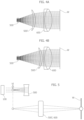
- FIG. 1 is an overall view of a lighting device
- FIG. 2 is an overall view of a lighting device according to embodiments of the present specification
- FIG. 3 is an overall view showing further possible features of a device according to embodiments of the present specification.
- FIGS. 4 A and 4 B show possible operating criteria of a device according to embodiments of the present specification
- FIG. 5 and FIGS. 6 A and 6 B show operating principles to be employed in a device according to embodiments of the present specification
- FIGS. 7 , 8 and 9 show possible operating conditions of a device according to embodiments of the present specification
- FIG. 10 is a perspective view of an optical component adapted to be employed in a device according to embodiments of the present specification.
- FIG. 11 shows possible operating conditions of a device according to embodiments of the present specification which employ a component as shown in FIG. 10 ,
- FIG. 12 is a perspective view of an optical component adapted to be employed in a device according to embodiments of the present specification.
- FIG. 13 shows possible operating conditions of a device according to embodiments of the present specification which employ a component as shown in FIG. 12 .
- Zoom optics (such as, e.g., combinations of positive and negative lenses, mobile lenses etc.) is a technical field which provides numerous solutions, based on cylindrical lenses and afocal lens systems.
- Document US 2017/284637 A1 describes an afocal system which constitutes an intermediate optical component between an illumination unit and a freeform reflector, in order to obtain a rectangular illuminance distribution on a wall.
- Document US 2019/187282 A1 describes the use of both cylindrical lenses and prisms in order to steer and expand a narrow laser beam, which is employed to scan and measure object distances
- document US 2004/090667 A1 describes the use of a cylindrical lens to change the shape and orientation of a light beam, in order to automatically detect the best focusing plane in a microscope.
- Both said documents concern the measurement of a distance from a lens (either a projection lens or a microscope lens).
- the goal pursued in one or more embodiments leads to adopting different solutions, e.g., as regards the splitting of the light beam by means of a prism.
- one or more embodiments envisage “exacerbating” the prism splitting effect by separating the light into multiple sub-beams, thanks to a—for instance six-faceted—pyramid which is not excessively steep (i.e., the height of the pyramid between the vertex and the base is small) in order to avoid colour separation, which would result in unpleasant projection colour artifacts.
- One or more embodiments therefore, avoid separating the light beam according to wavelengths, but rather aim at separating it angularly into smaller light beams, each virtually comprising all light wavelengths.
- the beam enlarging optics i.e., the cylindrical lens
- an already existing projection lens the afocal zoom lens
- an afocal projection lens has infinite effective focal length. Therefore, it conjugates a virtual object plane (positioned at infinity) to a virtual image plane (again positioned at infinity or equivalent, very far from the objective exit surface).
- a small-sized optics system having, e.g., a length of approximately 10 cm
- very far practically means greater than 5 m.
- Galilean telescope design which consists of a positive power lens (i.e. a convergent lens, the objective) and a negative power lens (i.e. a divergent lens, the eyepiece), wherein the focal points of both lenses coincide: this solution greatly reduces the overall telescope length compared to a classical Keplerian design, wherein both the objective lens and the eyepiece lens are positive; this translates into an advantage, because it further reduces the overall length of the system.
- An immediate advantage which can be obtained by introducing an afocal projection lens is the overall system compactness.
- a cylindrical lens placed at the afocal projection lens optics (but distinct therefrom) which is adapted to “elongate” or “squeeze” the light beam along the axis direction or along a direction orthogonal (perpendicular) to the optical axis;
- a transparent (e.g., glass) multi-faceted (e.g., six-faceted) pyramid prism thereby splitting the light beam into a plurality of different smaller sub-beams
- an axicon (a special kind of lens having a conical surface), thereby splitting the light beam into a virtually infinite number of smaller sub-beams which resolve into a ring.
- the first solution (cylindrical lens) enables for example to “elongate” or “squeeze” focused and unfocused hexagonal patterns (i.e., the virtual gobo plane obtained by a fly's eye lens integrator) into elongated hexagonal or oval shapes projected on a wall, wherein the orientation of the elongated pattern may be controlled by means of the zoom lens configuration or by rotating the cylindrical lens orthogonally to the optical axis.
- hexagonal patterns i.e., the virtual gobo plane obtained by a fly's eye lens integrator
- the second solution (faceted pyramid prism) allows projecting a plurality of separated light beams (at various distances from the optical axis, by modifying the magnification factor of the afocal optics, i.e., by zooming), with the result of producing, for example:
- the third solution enables projecting “infinite” separated light beam (at various distances from the optical axis, by changing the magnification factor of the afocal optics, i.e., by zooming), with the result of producing a ring-shaped distribution projected on a wall and optionally adapted to finally converge into a spot.
- reference 10 denotes on the whole a lighting device 10 including a light radiation source 100 .
- the lighting device 10 may have a mobile head and may be adapted to be employed in the show and entertainment sector.
- Device 10 and source 100 are shown deliberately schematically, in order to highlight the fact that one or more embodiments may be widely “transparent” as regards the specific features of device 10 and source 100 .
- source 100 may be of the sort including laser diodes operating in the red (R), green (G) and blue (B) wavelengths, the radiations whereof are collimated and combined with one another, for instance by means of dichroic filters, so as to provide a single RGB light beam, which may be subjected to mixing in a mixing unit comprising fly's eye optics.
- source 100 includes a (negative) output lens 500 , adapted to act on the light beam output from source 100 .
- negative lens we mean a divergent lens, adapted to reduce the convergence of the rays coming from an impinging collimated light source.
- the output beam is a divergent beam makes source 100 intrinsically safe from a photobiological point of view, making the maintenance 10 thereof easier.
- FIG. 1 shows a solution which may be adopted in order to adjustably conform said light beam, e.g., in an angular aperture range between 1° (substantially collimated beam) and 5° (slightly divergent beam).
- a frontal (positive) lens 600 of the afocal system i.e., the lens arranged more outwardly than (negative) lens 500 .
- the overall focal length of the projection optical system consisting of lenses 500 and 600
- FIG. 2 shows another solution which may be adopted in order to adjustably collimate the light beam output from source 100 .
- the solution of FIG. 2 may offer various advantages, such as for example a sharper projected image and a better filled light beam volume, together with the possibility of obtaining a more lightweight system.
- the beam shaping action from narrow to wide angle is controlled by lens 500 ′, which moves internally between lenses 500 and 600 , the movement thereof being “hidden” to the user because the first negative lens 500 and the outer positive lens 600 (for example, an achromatic doublet) stay fixed.
- the use of a simple negative lens 500 may reduce projection artifacts, such as halos.
- an effect wheel EW may be positioned along the light beam path.
- An effect wheel includes (in a way known in itself to the experts in the field) a set of filters, gobo images, frost filters, glass prisms and lenses, which are fixed or may be adapted to spin around their mechanical axis, for example driven by a motor ME.
- an aperture of the wheel is chosen (e.g., a given colour filter or the like) and aligned so that its axis is coincident with the projection optical axis.
- the effect wheel EW may be inserted between lens 500 and lens 500 ′, so as to interpose, in the light radiation path between lens 500 and lens 500 ′, an optical component which may be selected for example from a cylindrical lens CL, a prism P and an axicon A.
- the “intermediate” lens 500 ′ may move (e.g., under the action of motor SL) between:
- FIG. 4 A a first extreme position, retracted towards lens 500 , for a wide beam projection—see FIG. 4 A
- the light beam projected has a substantially circular profile.
- the propagation of the rays coming from the source is here shown as graphically circumscribed to the projection lens only, being it understood that the projection plane, e.g., a wall W, is generally located at a certain distance (greater than 5 m, for example) from the source.
- a spherical lens such as for example lens 500 , which is a negative bi-concave lens
- a cylindrical lens such as for example lens 500 , which is a negative bi-concave lens
- a cylindrical lens produces an astigmatic focus, which contains a first focal plane corresponding to the focus of the horizontal principal meridian, and a second focal plane corresponding to the focus of the vertical principal meridian. Between these focal planes, the astigmatic focus forms a circular region known as “circle of least confusion”.
- the (negative) lens 500 creates a virtual image VI (for example the hexagon of a fly's eye lenticular, which may be assumed as being infinity conjugated to source 100 ) in the focal point of lens 500 , which is located behind lens 500 itself.
- a virtual image VI for example the hexagon of a fly's eye lenticular, which may be assumed as being infinity conjugated to source 100
- the remaining components of the projection optics conjugate the virtual image to the position of wall W, where a real image hexagon is projected.
- both virtual images are created in two different positions along the optical axis, both virtual images having a different magnification along two orthogonal directions.
- a first hexagonal virtual image will be magnified more only along one direction (which may be defined as the y axis, for example) in a plane HPM perpendicular to the optical axis (z axis)—see FIG. 6 A ; and a second hexagonal virtual image will be magnified more only along one direction (which may be defined as the x axis, for example) in a plan VPM perpendicular to the optical axis (z axis)—see FIG. 6 B .
- lens 500 ′ of the projection optics When, as exemplified in FIG. 7 , lens 500 ′ of the projection optics is moved to conjugate to wall W the VPM virtual image in wide beam mode, a shape (hexagon) elongated in one (first) direction will be projected onto wall W.
- lens 500 ′ of the projection optics When, as exemplified in FIG. 8 , lens 500 ′ of the projection optics is moved to conjugate to wall W the circle of least confusion C (more or less halfway between the wide beam mode and the narrow beam mode), an at least approximately circular (e.g., not hexagonal) shape will be projected onto wall W.
- lens 500 ′ of the projection optics is moved to conjugate to wall W the HPM virtual image in narrow beam mode, a shape (hexagon) elongated in a (second) direction, orthogonal to the first direction as seen in FIG. 7 , will be projected onto wall W.
- an interesting effect may be created by using a transparent (e.g., glass) prism optical component, such as a multifaceted, e.g., six-faceted, pyramid, as shown in FIG. 10 .
- a transparent (e.g., glass) prism optical component such as a multifaceted, e.g., six-faceted, pyramid, as shown in FIG. 10 .
- prism P may be included in the effect wheel EW, but it is shown here, more generally, as a separate element.
- prism P may advantageously have a not excessively steep pyramid shape (i.e., the height of the pyramid between the vertex and the base thereof is short), which limits the appearance of projected colour artifacts.
- prism P may be placed between lens 500 and lens 500 ′.
- prism P may be oriented with the pyramid faces towards lens 500 ′.
- the single virtual image VI (e.g., a hexagon) may be split into six different “partial hexagon” images projected on wall W.
- This may take place separately (in the narrow beam mode illustrated in FIG. 11 ) or in a mutual overlapping (in the wide beam mode), therefore obtaining a star-shaped projected image.
- Prism P splits the single (e.g., hexagonal) virtual image H 1 created by lens 500 for example into six separated hexagonal virtual images H 2 .
- the components of the projection lens optics conjugate the virtual hexagon images to the position of wall W, where a real image hexagon is projected.
- the projected images may therefore appear partially vignetted and defocused in the outer region thereof.
- the single image (hexagon H 1 ) is defocused.
- the split images (hexagons H 2 ) are defocused;
- the single image is even more defocused.
- the split images are further defocused, until they touch each other creating a sort of “daisy” image;
- the single image is completely defocused.
- the split images are completely defocused, and they overlap each other thus creating a star-shaped compact image (the star having a number of points corresponding to the number of facets, e.g., six, of prism P).
- An axicon is a lens comprising any optical material and having a conical surface. As far as the present case is concerned, it may be considered as a “degeneration” of prism P into a pyramid with an infinite number of facets, and therefore a cone.
- the axicon A may be included in the effect wheel EW, but it is here more generally considered as a separate component.
- axicon A may have a not excessively steep conical shape (i.e., the height of the cone from the vertex to the base is short), which limits the appearance of colour artifacts in the projected image.
- axicon A may be placed between lens 500 and lens 500 ′.
- axicon A may be oriented with the conical surface facing towards lens 500 ′.
- Axicon A splits the single (e.g., hexagon) virtual image created by lens 500 (hexagon H 1 in FIG. 13 ) into a virtual infinity of separate virtual images (hexagons HX in FIG. 13 ) which combine together into a ring-shaped distribution.
- the components of the projection optics conjugate the virtual hexagon images to the position of wall W where a real image hexagon is projected.
- the rays coming from the light source 100 contribute to the creation of the projected ring (indeed an overlapping of an infinite number of images such as hexagons).
- One or more embodiments may therefore envisage removing the condenser optics and the gobo plane and introducing an optical component such as an afocal projection lens, which helps reducing the length of a narrow beam projection optics.
- the light beam will result in a spot elongated in one direction, the x-direction ( FIG. 7 , for example) over a projection plane closer to the lens, and elongated in the orthogonal direction, the y-direction ( FIG. 9 , for example) over a projection plane further away from the lens, thereby providing a twisted appearance of the light beam;
- splitting the main light beam into smaller secondary light beams sub-beams
- Arranging on an effect wheel such as EW at least two optical elements (and optionally all three optical elements) selected from cylindrical lens CL, prism P and/or axicon A enables obtaining the previously described effects selectively, e.g., according to the envisaged application and/or according to the choices of the lighting director.
- a lighting device (e.g., 10 ) as illustrated herein may comprise a light source (e.g., 100 ) configured to emit a light beam through an afocal projection optics (e.g., 500 , 500 ′, 600 ) along a propagation path of the light beam from a negative lens (e.g., 500 ) to a positive lens (e.g., 600 ), wherein the lighting device comprises:
- a further negative lens e.g., 500 ′ interposed and mobile (for example by means of motorization SL) along the propagation path of the light beam from the negative lens to the positive lens, and
- the optical element interposed in the propagation path of the light beam between the negative lens and the further negative lens, the optical element comprising an optical element selected from a cylindrical lens (e.g., CL), a prism (e.g., P) and an axicon (e.g., A).
- a cylindrical lens e.g., CL
- a prism e.g., P
- an axicon e.g., A
- either the device may be stably equipped with (only) one of such optical elements (CL, P or A), or it may be configured so as to enable replacing one optical element with another according to the user's needs or tastes.
- a lighting device as illustrated herein may comprise a mobile support member (e.g., EW) carrying at least two different optical elements selected from a cylindrical lens (CL), a prism (P) and an axicon (A), the mobile support member being configured (e.g., ME) to selectively interpose in the propagation path of the light beam, between the negative lens and the further negative lens, an optical element selected from said at least two different optical elements, so that it may switch for example:
- EW mobile support member
- CL cylindrical lens
- P prism
- A axicon
- the mobile support member may comprise a motorized (e.g., ME) effect wheel (EW).
- ME motorized effect wheel
- the presence of the optical element (CL, P or A) enables obtaining imaging optical effects without a gobo and by means of an afocal projection optics.
- the negative lens (e.g., 500 ) may comprise a simple negative lens.
- the positive lens (e.g., 600 ) may comprise an achromatic doublet.
- said prism may include a pyramidal prism (e.g., P).
- the pyramidal prism may be interposed in the propagation path of the light beam between the negative lens and the further negative lens, with the tapered side thereof facing towards the positive lens (i.e., with the pyramid tapered side facing towards the further negative lens 500 ′ and the base of the prism facing towards the negative lens 500 ).
- the axicon may be interposed in the propagation path of the light beam between the negative lens and the further negative lens, with the tapered side thereof facing towards the positive lens (i.e., with the cone tapered side facing towards the further negative lens 500 ′ and the cone base facing towards the negative lens 500 ).
- a method of operating a lighting device as illustrated herein may comprise moving the further negative lens ( 500 ′, e.g., by means of motorization SL) along the propagation path of the light beam, bringing it closer to the negative lens and away from the positive lens, or moving it away from the negative lens and bringing it closer to the positive lens.
- a method as illustrated herein may comprise selectively changing the optical element (e.g., CL, P, A) interposed in the propagation path of the light beam, thereby enabling switching, for example:
Landscapes
- Engineering & Computer Science (AREA)
- General Engineering & Computer Science (AREA)
- Physics & Mathematics (AREA)
- General Physics & Mathematics (AREA)
- Optics & Photonics (AREA)
- Lenses (AREA)
- Microscoopes, Condenser (AREA)
- Control Of Vending Devices And Auxiliary Devices For Vending Devices (AREA)
Abstract
Description
-
Lighting device 10 -
Light source 100 - Fixed
negative lens 500 - Mobile
negative lens 500′ - Lens motorization ML
- Fixed
positive lens 600 - Effect wheel EW
- Effect wheel motorization ME
- Projection surface (wall) W
- Cylindrical lens CL
- Virtual image VPM, HPM
- Circle of least confusion C
- Prism P
- Single image H1
- Split images H2
- Axicon A
- Virtual images VI
- Split images HX
Claims (9)
Applications Claiming Priority (2)
| Application Number | Priority Date | Filing Date | Title |
|---|---|---|---|
| IT102021000000377 | 2021-01-11 | ||
| IT102021000000377A IT202100000377A1 (en) | 2021-01-11 | 2021-01-11 | LIGHTING DEVICE AND CORRESPONDING OPERATION PROCEDURE |
Publications (2)
| Publication Number | Publication Date |
|---|---|
| US20220221128A1 US20220221128A1 (en) | 2022-07-14 |
| US11649946B2 true US11649946B2 (en) | 2023-05-16 |
Family
ID=75111821
Family Applications (1)
| Application Number | Title | Priority Date | Filing Date |
|---|---|---|---|
| US17/572,221 Active US11649946B2 (en) | 2021-01-11 | 2022-01-10 | Lighting device with afocal projection optics and corresponding method of operation |
Country Status (4)
| Country | Link |
|---|---|
| US (1) | US11649946B2 (en) |
| EP (1) | EP4027053A1 (en) |
| CN (1) | CN114815467A (en) |
| IT (1) | IT202100000377A1 (en) |
Citations (14)
| Publication number | Priority date | Publication date | Assignee | Title |
|---|---|---|---|---|
| US20030076679A1 (en) * | 2001-10-18 | 2003-04-24 | Asml Us, Inc. | Advanced illumination system for use in microlithography |
| US20040090667A1 (en) | 2002-03-22 | 2004-05-13 | Carl-Zeiss-Stiftung Trading As Carl Zeiss | Microscopy system |
| US20100321940A1 (en) * | 2009-05-22 | 2010-12-23 | Clay Paky S.P.A. | Lighting fixture zoom device, and lighting fixture comprising said zoom device |
| US20130155648A1 (en) * | 2010-08-24 | 2013-06-20 | Osram Ag | Colour-tunable light source unit with phosphor element |
| US20140131327A1 (en) * | 2012-11-12 | 2014-05-15 | Mitsubishi Heavy Industries, Ltd. | Optical system and laser processing apparatus |
| US20150260372A1 (en) | 2014-03-12 | 2015-09-17 | Clay Paky S.P.A. | Stage light fixture |
| US9140425B2 (en) | 2013-03-04 | 2015-09-22 | Electronic Theatre Controls, Inc. | Cyc attachment for a light engine |
| US20160238217A1 (en) * | 2015-02-16 | 2016-08-18 | D.T.S. Illuminazione S.R.L. | Projector of light beams |
| US20160377256A1 (en) * | 2015-06-29 | 2016-12-29 | Martin Professional Aps | Prism effect system comprising multi-regional color filter and multi-faceted prism |
| US20170284637A1 (en) | 2016-04-05 | 2017-10-05 | Osram Gmbh | Illumination apparatus for producing a rectangular light distribution in an illumination plane |
| US20180119924A1 (en) | 2016-11-03 | 2018-05-03 | Electronic Theatre Controls, Inc. | Cyc light |
| US20190041039A1 (en) | 2017-09-01 | 2019-02-07 | Robe Lighting S.R.O. | Zoom Optical System |
| US20190187282A1 (en) | 2017-12-14 | 2019-06-20 | Arnold & Richter Cine Technik Gmbh & Co. Betriebs Kg | Camera system with laser-based rangefinder |
| US20190360665A1 (en) * | 2018-05-28 | 2019-11-28 | D.T.S. Illuminazione S.R.L. | Projector of a light beam |
Family Cites Families (6)
| Publication number | Priority date | Publication date | Assignee | Title |
|---|---|---|---|---|
| TWM269477U (en) * | 2004-11-10 | 2005-07-01 | Nucam Corp | Stepwise variable zoom lens |
| EP1870756A1 (en) * | 2006-06-22 | 2007-12-26 | BCI Finanz AG | Projection objective lens having a fixed focal length for digital projection |
| EP3112745B1 (en) * | 2015-06-29 | 2018-08-01 | Martin Professional ApS | Prism effect system for light fixture with inverted multi-facet prisms |
| CN205003348U (en) * | 2015-07-16 | 2016-01-27 | 江苏大学 | A zoom optical system for projecting apparatus |
| CN206573764U (en) * | 2017-02-24 | 2017-10-20 | 广州星云舞台灯光设备有限公司 | A kind of stage lighting varifocal imaging optical system |
| CN108037632B (en) * | 2017-12-27 | 2020-09-25 | 海信视像科技股份有限公司 | Laser lighting device for projection, projection system and adjusting method thereof |
-
2021
- 2021-01-11 IT IT102021000000377A patent/IT202100000377A1/en unknown
-
2022
- 2022-01-05 EP EP22150330.3A patent/EP4027053A1/en active Pending
- 2022-01-10 US US17/572,221 patent/US11649946B2/en active Active
- 2022-01-11 CN CN202210025197.9A patent/CN114815467A/en active Pending
Patent Citations (14)
| Publication number | Priority date | Publication date | Assignee | Title |
|---|---|---|---|---|
| US20030076679A1 (en) * | 2001-10-18 | 2003-04-24 | Asml Us, Inc. | Advanced illumination system for use in microlithography |
| US20040090667A1 (en) | 2002-03-22 | 2004-05-13 | Carl-Zeiss-Stiftung Trading As Carl Zeiss | Microscopy system |
| US20100321940A1 (en) * | 2009-05-22 | 2010-12-23 | Clay Paky S.P.A. | Lighting fixture zoom device, and lighting fixture comprising said zoom device |
| US20130155648A1 (en) * | 2010-08-24 | 2013-06-20 | Osram Ag | Colour-tunable light source unit with phosphor element |
| US20140131327A1 (en) * | 2012-11-12 | 2014-05-15 | Mitsubishi Heavy Industries, Ltd. | Optical system and laser processing apparatus |
| US9140425B2 (en) | 2013-03-04 | 2015-09-22 | Electronic Theatre Controls, Inc. | Cyc attachment for a light engine |
| US20150260372A1 (en) | 2014-03-12 | 2015-09-17 | Clay Paky S.P.A. | Stage light fixture |
| US20160238217A1 (en) * | 2015-02-16 | 2016-08-18 | D.T.S. Illuminazione S.R.L. | Projector of light beams |
| US20160377256A1 (en) * | 2015-06-29 | 2016-12-29 | Martin Professional Aps | Prism effect system comprising multi-regional color filter and multi-faceted prism |
| US20170284637A1 (en) | 2016-04-05 | 2017-10-05 | Osram Gmbh | Illumination apparatus for producing a rectangular light distribution in an illumination plane |
| US20180119924A1 (en) | 2016-11-03 | 2018-05-03 | Electronic Theatre Controls, Inc. | Cyc light |
| US20190041039A1 (en) | 2017-09-01 | 2019-02-07 | Robe Lighting S.R.O. | Zoom Optical System |
| US20190187282A1 (en) | 2017-12-14 | 2019-06-20 | Arnold & Richter Cine Technik Gmbh & Co. Betriebs Kg | Camera system with laser-based rangefinder |
| US20190360665A1 (en) * | 2018-05-28 | 2019-11-28 | D.T.S. Illuminazione S.R.L. | Projector of a light beam |
Also Published As
| Publication number | Publication date |
|---|---|
| EP4027053A1 (en) | 2022-07-13 |
| US20220221128A1 (en) | 2022-07-14 |
| CN114815467A (en) | 2022-07-29 |
| IT202100000377A1 (en) | 2022-07-11 |
Similar Documents
| Publication | Publication Date | Title |
|---|---|---|
| JP7486701B2 (en) | Axially Asymmetric Image Source for Head-Up Displays | |
| US7554737B2 (en) | Illumination device and method using adaptable source and output format | |
| US5270859A (en) | Optical instrument with micro-lenses | |
| EP3130962B1 (en) | Illumination device | |
| US9019597B2 (en) | Device for short-distance projection at a reasonably large angle with zoom and focusing | |
| US10330293B2 (en) | Collimation and homogenization system for an LED luminaire | |
| US7210820B2 (en) | Methods and apparatuses for homogenizing light | |
| CN105929560B (en) | Broadband far-field super-resolution imaging device | |
| US7411735B2 (en) | Illumination system incorporating collimated light source | |
| EP1356348A2 (en) | Illumination device and method for laser projector | |
| JP2003091045A (en) | Illumination optical system and projection display device | |
| CN104656378A (en) | Illumination system of a microlithographic projection exposure apparatus | |
| NL8801348A (en) | EXPOSURE SYSTEM. | |
| US10132470B2 (en) | Versatile beam and wash optical system for an automated luminaire | |
| EP0472597A1 (en) | Continuously focusable optical system incorporating an afocal variator optical system | |
| US11649946B2 (en) | Lighting device with afocal projection optics and corresponding method of operation | |
| US3661439A (en) | Telescopic kaleidoscope | |
| CN108761982B (en) | Projection light collecting system | |
| Schreiber et al. | Light Shaping with Micro-optical Irregular Fly´ s Eye Condensers | |
| US6886944B2 (en) | Projector brightness enhancement using rectilinear apertures | |
| CN103728718A (en) | Multispectral microscope multiple light lighting method and device | |
| US7944624B2 (en) | Method for homogenizing light | |
| KR101168251B1 (en) | Optical system and corresponding optical element | |
| JPH09509265A (en) | High symmetry optical system | |
| JPH06160757A (en) | Method and a small viewing angle scanner for obtaining a small viewing angle scan |
Legal Events
| Date | Code | Title | Description |
|---|---|---|---|
| FEPP | Fee payment procedure |
Free format text: ENTITY STATUS SET TO UNDISCOUNTED (ORIGINAL EVENT CODE: BIG.); ENTITY STATUS OF PATENT OWNER: LARGE ENTITY |
|
| AS | Assignment |
Owner name: CLAY PAKY S.P.A., ITALY Free format text: ASSIGNMENT OF ASSIGNORS INTEREST;ASSIGNORS:FRISON, RENATO;ALFIER, ALBERTO;QUADRI, ARIS;REEL/FRAME:058858/0741 Effective date: 20220103 Owner name: OSRAM GMBH, GERMANY Free format text: ASSIGNMENT OF ASSIGNORS INTEREST;ASSIGNORS:FRISON, RENATO;ALFIER, ALBERTO;QUADRI, ARIS;REEL/FRAME:058858/0741 Effective date: 20220103 |
|
| STPP | Information on status: patent application and granting procedure in general |
Free format text: DOCKETED NEW CASE - READY FOR EXAMINATION |
|
| STPP | Information on status: patent application and granting procedure in general |
Free format text: NON FINAL ACTION MAILED |
|
| STPP | Information on status: patent application and granting procedure in general |
Free format text: RESPONSE TO NON-FINAL OFFICE ACTION ENTERED AND FORWARDED TO EXAMINER |
|
| AS | Assignment |
Owner name: CLAY PAKY S.P.A., ITALY Free format text: ASSIGNMENT OF ASSIGNORS INTEREST;ASSIGNOR:OSRAM GMBH;REEL/FRAME:062136/0667 Effective date: 20221117 |
|
| STCF | Information on status: patent grant |
Free format text: PATENTED CASE |
|
| AS | Assignment |
Owner name: CLAY PAKY S.R.L., ITALY Free format text: ASSIGNMENT OF ASSIGNORS INTEREST;ASSIGNOR:CLAY PAKY S.P.A.;REEL/FRAME:066510/0875 Effective date: 20231018 |