US11647703B2 - Cable use system, overhead moving device, and cable use method - Google Patents
Cable use system, overhead moving device, and cable use method Download PDFInfo
- Publication number
- US11647703B2 US11647703B2 US17/365,431 US202117365431A US11647703B2 US 11647703 B2 US11647703 B2 US 11647703B2 US 202117365431 A US202117365431 A US 202117365431A US 11647703 B2 US11647703 B2 US 11647703B2
- Authority
- US
- United States
- Prior art keywords
- cable
- cutting
- tree
- unit
- holding
- Prior art date
- Legal status (The legal status is an assumption and is not a legal conclusion. Google has not performed a legal analysis and makes no representation as to the accuracy of the status listed.)
- Active, expires
Links
Images


Classifications
-
- A—HUMAN NECESSITIES
- A01—AGRICULTURE; FORESTRY; ANIMAL HUSBANDRY; HUNTING; TRAPPING; FISHING
- A01G—HORTICULTURE; CULTIVATION OF VEGETABLES, FLOWERS, RICE, FRUIT, VINES, HOPS OR SEAWEED; FORESTRY; WATERING
- A01G3/00—Cutting implements specially adapted for horticultural purposes; Delimbing standing trees
- A01G3/08—Other tools for pruning, branching or delimbing standing trees
-
- A—HUMAN NECESSITIES
- A01—AGRICULTURE; FORESTRY; ANIMAL HUSBANDRY; HUNTING; TRAPPING; FISHING
- A01G—HORTICULTURE; CULTIVATION OF VEGETABLES, FLOWERS, RICE, FRUIT, VINES, HOPS OR SEAWEED; FORESTRY; WATERING
- A01G23/00—Forestry
- A01G23/003—Collecting felled trees
-
- B—PERFORMING OPERATIONS; TRANSPORTING
- B66—HOISTING; LIFTING; HAULING
- B66C—CRANES; LOAD-ENGAGING ELEMENTS OR DEVICES FOR CRANES, CAPSTANS, WINCHES, OR TACKLES
- B66C21/00—Cable cranes, i.e. comprising hoisting devices running on aerial cable-ways
-
- A—HUMAN NECESSITIES
- A01—AGRICULTURE; FORESTRY; ANIMAL HUSBANDRY; HUNTING; TRAPPING; FISHING
- A01G—HORTICULTURE; CULTIVATION OF VEGETABLES, FLOWERS, RICE, FRUIT, VINES, HOPS OR SEAWEED; FORESTRY; WATERING
- A01G23/00—Forestry
- A01G23/003—Collecting felled trees
- A01G23/006—Log skidders
-
- A—HUMAN NECESSITIES
- A01—AGRICULTURE; FORESTRY; ANIMAL HUSBANDRY; HUNTING; TRAPPING; FISHING
- A01G—HORTICULTURE; CULTIVATION OF VEGETABLES, FLOWERS, RICE, FRUIT, VINES, HOPS OR SEAWEED; FORESTRY; WATERING
- A01G23/00—Forestry
- A01G23/02—Transplanting, uprooting, felling or delimbing trees
- A01G23/08—Felling trees
- A01G23/091—Sawing apparatus specially adapted for felling trees
Landscapes
- Life Sciences & Earth Sciences (AREA)
- Biodiversity & Conservation Biology (AREA)
- Ecology (AREA)
- Forests & Forestry (AREA)
- Environmental Sciences (AREA)
- Engineering & Computer Science (AREA)
- Mechanical Engineering (AREA)
- Carriers, Traveling Bodies, And Overhead Traveling Cranes (AREA)
- Load-Engaging Elements For Cranes (AREA)
- Forklifts And Lifting Vehicles (AREA)
- Working Measures On Existing Buildindgs (AREA)
Abstract
A cable use system includes a plurality of support posts, a cable supported by the support posts, a winding device configured to wind the cable, a hoisting device coupled to the cable and configured to move in an air when the cable is wound by the winding device, and a cutting device hung from the hoisting device. The cutting device includes a cutting unit configured to cut a surface side of a tree all around.
Description
This application claims priority to Japanese Patent Application No. 2020-169287 filed on Oct. 6, 2020, incorporated herein by reference in its entirety.
The disclosure relates to a technology for cutting part of a tree by using cables.
Japanese Unexamined Patent Application Publication No. 2008-109918 (JP 2008-109918 A) describes a thinned wood transport system that transports thinned wood from a logging site to an unloading site. The thinned wood transport system includes a tower yarder placed near the unloading site on a work road, a first winch installed in the tower yarder to wind a first wire, a second winch installed in the tower yarder to wind a second wire, a plurality of pulleys coupled in the middle of a traveling route of the second wire to change a traveling direction of the second wire, a loading tool that hooks thinned wood, and a plurality of zigzag pulleys coupled in the middle of a traveling route of the loading tool to change the traveling direction of the loading tool.
Work to enter a forest and thin trees needs efforts of operators. In a poorly managed forest, trees not subjected to thinning can also be narrow and, therefore, there are concerns that such trees may become weak against wind and snow, or the like, and die down if many trees around narrow trees are excessively removed at a time.
The disclosure provides a technology to stably facilitate the growth of remaining trees while reducing an effort to thin trees.
An aspect of the disclosure relates to a cable use system. The cable use system includes a plurality of support posts, a cable supported by the support posts, a winding device configured to wind the cable, a hoisting device coupled to the cable and configured to move in an air when the cable is wound by the winding device, and a cutting device hung from the hoisting device. The cutting device includes a cutting unit configured to cut a surface side of a tree all around.
Another aspect of the disclosure relates to an overhead moving device hung from the cable supported by support posts and configured to move in an air when the cable is wound. The overhead moving device includes a hoisting device coupled to the cable and a cutting device hung from the hoisting device. The cutting device includes a cutting unit configured to cut a surface side of a tree all around.
Further another aspect of the disclosure relates to a cable use method using a cable use system. The cable use system includes a winding device configured to wind a cable supported by support posts, a hoisting device coupled to the cable and configured to move in an air when the cable is wound by the winding device, a holding device hung from the hoisting device, and a cutting device hung from the hoisting device. The cable use method includes holding a tree by the holding device, and cutting a surface side of the tree by the cutting device all around.
According to the aspects of the disclosure, it is possible to provide a technology to stably facilitate the growth of remaining trees while reducing an effort to thin trees.
Features, advantages, and technical and industrial significance of exemplary embodiments of the disclosure will be described below with reference to the accompanying drawings, in which like signs denote like elements, and wherein:
The cable use system 1 is a so-called H-shaped cable use system and is capable of hoisting trees logged in a forest with the main cables 12 and the operation cables 14 stretched in the air and transporting the trees to near a yarding site 26. Thus, trees are transported from a forest even when there is no road. The cable use system 1 includes the cutting device 44, so the cable use system 1 is capable of subjecting trees to girdling treatment by cutting the surface sides of the trees.
The four support posts 10 are erected at positions suitable for installation and determined based on the arrangement of standing trees and the position of the yarding site 26. The size of each support post 10 is set to the range of about five meters to 10 meters according to the size and the like of the cable use system 1.
Each of the main cables 12 and the operation cables 14 is fixed to the support post 10 as a cable or wrapped around a pulley of the support post 10. The first main cable 12 a is fixed to the first support post 10 a and the second support post 10 b. The second main cable 12 b is fixed to the third support post 10 c and the fourth support post 10 d. The first main cable 12 a and the second main cable 12 b function as rails in the air. The first main cable 12 a and the second main cable 12 b are provided so as not to intersect with each other. The length of each main cable 12 is set to a range from about 300 meters to about 2000 meters.
The operation cable 14 functions as a running cable to be wound by the moving device 16 or the winch 24. The first operation cable 14 a, the second operation cable 14 b, the third operation cable 14 c, and the fourth operation cable 14 d are routed through the pulleys respectively provided at the support posts 10. One end of each of the first operation cable 14 a, the second operation cable 14 b, the third operation cable 14 c, and the fourth operation cable 14 d is coupled to an associated one of the moving devices 16, and the other end is coupled to the winch 24. The first operation cable 14 a is routed from the winch 24 and coupled to the first moving device 16 a via the second support post 10 b and the first support post 10 a. The second operation cable 14 b is routed from the winch 24 and coupled to the first moving device 16 a via the second support post 10 b. The third operation cable 14 c is routed from the winch 24 and coupled to the second moving device 16 b via the fourth support post 10 d and the third support post 10 c. The fourth operation cable 14 d is routed from the winch 24 and coupled to the second moving device 16 b via the fourth support post 10 d. The fifth operation cable 14 e and the sixth operation cable 14 f are each coupled to the hoisting device 18 and an associated one of the moving devices 16.
The moving devices 16 are respectively supported by the main cables 12 and are movable along the main cables 12. The first operation cable 14 a, the second operation cable 14 b, and the fifth operation cable 14 e are coupled to the first moving device 16 a. The third operation cable 14 c, the fourth operation cable 14 d, and the sixth operation cable 14 f are coupled to the second moving device 16 b. The fifth operation cable 14 e couples the first moving device 16 a and the hoisting device 18. The sixth operation cable 14 f couples the second moving device 16 b and the hoisting device 18. The moving devices 16 have the function to wind and unwind the fifth operation cable 14 e and the sixth operation cable 14 f in accordance with a wirelessly transmitted command signal.
The hoisting device 18 is coupled to a holding device 19 by a wire for lifting and lowering. The cutting device 44 is attached to the holding device 19. The holding device 19 and the cutting device 44 are hung from the hoisting device 18. Each of the guide pulleys 22 changes the direction of the wrapped operation cable 14. The winch 24 functions as a winch to wind each of the operation cables 14 and has drums and drive sources for winding or unwinding the operation cables 14, respectively.
The operation of the cable use system 1 will be described. The winch 24 winds one of the first operation cable 14 a and the second operation cable 14 b and unwinds the other one to move the first moving device 16 a along the first main cable 12 a. In addition, the winch 24 winds one of the third operation cable 14 c and the fourth operation cable 14 d and unwinds the other one to move the second moving device 16 b along the second main cable 12 b. Thus, the hoisting device 18 is displaced along the main cables 12.
The moving devices 16 wind one of the fifth operation cable 14 e and the sixth operation cable 14 f and unwind the other one to cause the hoisting device 18 to move between the first moving device 16 a and the second moving device 16 b. Thus, the hoisting device 18 is moved in a horizontal direction within a region surrounded by the four support posts 10.
In this way, the winch 24 and the moving devices 16 function as a winding device capable of winding cables. The winding device enables the hoisting device 18 to move in the horizontal direction in the air by winding the operation cables 14 (cables).
In the configuration of the cable use system 1 shown in FIG. 1 , the moving devices 16 that respectively wind the fifth operation cable 14 e and the sixth operation cable 14 f are respectively coupled to the main cables 12; however, the cable use system 1 is not limited to this configuration. When the fifth operation cable 14 e and the sixth operation cable 14 f are extended to the position of the winch 24, the winch 24 has the function to wind the moving devices 16. The winch 24 is not limited to the configuration in which individual winches are concentrated at one location. The winch 24 may be configured such that individual winches are provided one by one at the support posts 10. In this way, the winding device may be integrated or separated.
The holding device 19 includes an actuator 30, a first holding unit 32, a second holding unit 34, the first wire 36, a second wire 40, a first motor 38, and a second motor 42. The actuator 30, the first holding unit 32, the second holding unit 34, the first motor 38, and the second motor 42 are remotely controllable and controlled by a controller (described later).
One end of the first wire 36 is fixed to the actuator 30, and the other end side of the first wire 36 is coupled to the actuator 30 so as to be wound and unwound. The first wire 36 is coupled to the hoisting device 18 via pulleys. The first motor 38 is provided on the actuator 30 and is capable of winding and unwinding the first wire 36. The holding device 19 moves in an up and down direction with respect to the hoisting device 18 by driving the first motor 38.
The first holding unit 32 and the second holding unit 34 are hung by the second wire 40 from the actuator 30. One end of the second wire 40 is fixed to the actuator 30, the middle part of the second wire 40 is coupled to the first holding unit 32 via a pulley 32 b provided on the first holding unit 32, and the other end of the second wire 40 is coupled to the actuator 30 such that the second wire 40 can be wound and unwound. The second motor 42 is provided on the actuator 30 and is capable of winding and unwinding the second wire 40. The first holding unit 32 moves in the up and down direction with respect to the actuator 30 by driving the second motor 42.
The first holding unit 32 includes a pair of clamping portions 32 a and the pulley 32 b. The pair of clamping portions 32 a can be driven to close and open and clamps the outer periphery of a tree. The pair of clamping portions 32 a approaches a tree in an open state and closes to clamp the tree.
The second holding unit 34 is a manipulator and is fixed to the second wire 40. The second holding unit 34 is provided between the actuator 30 and the first holding unit 32 and is located above the first holding unit 32. The second holding unit 34 includes a grip portion 34 a and an arm portion 34 b. The grip portion 34 a is located at the distal end portion of the second holding unit 34 and grips the outer periphery of a tree. The arm portion 34 b has a plurality of joints. The arm portion 34 b is capable of bringing the grip portion 34 a close to a tree by moving in a direction away from the second wire 40. After the grip portion 34 a holds the tree, the arm portion 34 b contracts to bring the grip portion 34 a close to the second wire 40. Thus, the first holding unit 32 and the cutting device 44 approach the tree. The first holding unit 32 and the second holding unit 34 are capable of holding a logged tree and transport the tree in the air through winding of the winding device.
The holding device 19 is capable of moving the actuator 30 up and down by driving the first motor 38 and is capable of moving the first holding unit 32 up and down by driving the second motor 42. Thus, the first holding unit 32 and the second holding unit 34 each can be caused to hold a tree at an adequate position. The cutting device 44 is provided on the lower part of the first holding unit 32.
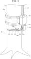
In girdling treatment, the cambium 20 c is cut all around by the cutting unit 44 a. When the tree 20 does not fall down, the sapwood 20 d may be cut in to a certain extent, and it is desirable to leave the heartwood 20 e such that the tree 20 does not fall down.
When the cambium 20 c is cut all around, the tree 20 cannot absorb nutrients taken in from a ground to above the slit portion 20 a and dies down while standing. For this reason, the tree 20 dies down and is removed over time, so it is possible to stably grow desired trees while reducing influences on remaining trees in comparison with the case where thinning of a large number of trees 20 is performed at a time. The trees 20 subjected to girdling treatment are capable of supporting other trees while dying down, so other trees grow while maintaining a state where the other trees can stand wind and snow, and the like.
The cutting unit 44 a is an electrically-powered circular saw and is capable of cutting the surface side of the tree 20. When the cutting unit 44 a cuts in the tree 20 to a predetermined depth, the housing of the cutting unit 44 a contacts the surface of the tree 20 and is stopped to cut in toward the center of the tree 20. In other words, the housing of the cutting unit 44 a functions as a stopper that stops cutting in toward the center of the tree 20 at or greater than a predetermined distance. The cutting unit 44 a may be a chain saw. The cutting unit 44 a is slidably supported by the first rail portion 44 b. The cutting unit 44 a is equipped with the first drive unit 44 f for sliding along the first rail portion 44 b.
The first rail portion 44 b and the second rail portion 44 c are curved along the circumferential direction of the tree 20 and formed in a circular arc shape. The first rail portion 44 b and the second rail portion 44 c are provided parallel to each other. The first rail portion 44 b and the second rail portion 44 c are coupled as one unit and are slidable with respect to the first holding unit 32 and the supporting portion 44 d. The first rail portion 44 b is located on a radially inner side, and the second rail portion 44 c is located on a radially outer side. The length of each of the first rail portion 44 b and the second rail portion 44 c is set to about a range of 180 degrees to 200 degrees in rotation angle. The radius of curvature of the first rail portion 44 b is set so as to be greater than the radius of the tree 20.
The supporting portion 44 d supports the second rail portion 44 c such that the second rail portion 44 c is slidable. The supporting portion 44 d is equipped with the second drive unit 44 g for sliding the second rail portion 44 c. The upper end of the supporting portion 44 d is coupled to the first holding unit 32.
The rotary mechanism 44 h is provided between the cutting unit 44 a and the first drive unit 44 f The rotary mechanism 44 h is, for example, capable of rotating along the horizontal direction and moving the cutting unit 44 a toward a radially inner side with respect to the first drive unit 44 f Through rotation of the rotary mechanism 44 h, the cutting unit 44 a can be placed at two positions, that is, a state where the cutting unit 44 a contacts with the tree 20 and a state where the cutting unit 44 a is spaced apart from the tree 20. A rotation axis of the rotary mechanism 44 h is not limited to a vertical direction and may be a tangential direction of the first rail portion 44 b.
The urging portion 44 e urges the cutting unit 44 a radially inward, that is, urges the cutting unit 44 a in a direction to approach the tree 20. The urging portion 44 e is provided in the rotary mechanism 44 h and urges the cutting unit 44 a in a rotation direction of the rotary mechanism 44 h. With the urging portion 44 e, a state where the cutting unit 44 a is pressed against the surface side of the tree 20 is maintained. The urging portion 44 e is a spring member and urges the cutting unit 44 a radially inward with a predetermined load or greater. With the urging portion 44 e, the cutting unit 44 a can be pressed against the tree 20 with a low-cost configuration. A component to press the cutting unit 44 a against the tree 20 is not limited to the urging portion 44 e. The cutting unit 44 a may be moved radially inward through motor control to be pressed against the tree 20.
The operation of the cutting device 44 will be described. After the first holding unit 32 holds the tree 20, the cutting unit 44 a is set at one end of the first rail portion 44 b, the supporting portion 44 d is set at the other end of the second rail portion 44 c, and the drive of the cutting unit 44 a is started. In other words, at the time of the start of drive of the cutting unit 44 a, the cutting unit 44 a is located on the back side of the tree 20 away from the supporting portion 44 d.
Subsequently, the rotary mechanism 44 h is driven, the cutting unit 44 a is brought into contact with the tree 20, and is urged by the urging portion 44 e toward the tree 20. In a state where the cutting unit 44 a is pressed against the tree 20, the second rail portion 44 c slides relative to the supporting portion 44 d by the second drive unit 44 g. Thus, the cutting unit 44 a moves in the circumferential direction together with the second rail portion 44 c and cuts the surface side of the tree 20 over the range of 180 degrees or greater.
After the second drive unit 44 g slides from the other end of the second rail portion 44 c to one end, the slide caused by the second drive unit 44 g ends, and the first drive unit 44 f starts sliding on the first rail portion 44 b. When the slide of the second drive unit 44 g completes, the cutting unit 44 a is located near the supporting portion 44 d. After the first drive unit 44 f slides from one end of the first rail portion 44 b to the other end, the cutting unit 44 a completes moving all around the tree 20, so the drive is stopped, and girdling treatment ends.
Since the slide of the first drive unit 44 f along the first rail portion 44 b and the slide of the second drive unit 44 g along the second rail portion 44 c each are movement over a rotation angle greater than or equal to 180 degrees, the cutting unit 44 a is capable of cutting the surface side of the tree 20 all around.
In this way, the first drive unit 44 f and the second drive unit 44 g (each will be referred to as drive unit when they are not distinguished from each other) move the cutting unit 44 a in the circumferential direction. Each of the first rail portion 44 b and the second rail portion 44 c (each will be referred to as rail portion when they are not distinguished from each other) is capable of guiding movement of the cutting unit 44 a in the circumferential direction by an associated one of the drive units 44 f, 44 g.
Control to lower the holding device 19 and control to cause the second holding unit 34 to hold the tree 20 may be executed by a program provided in advance or may be executed by operation of an operator. Alternatively, control of the cable use system 1 may be a combination of a program and operation of an operator. For example, an operator controls the cable use system 1 while watching an image transmitted from a camera provided at the hoisting device 18, the actuator 30, or the like.
In FIG. 6C , the cutting device 44 is driven in a state where the first holding unit 32 and the second holding unit 34 are holding the tree 20, to form the slit portion 20 a all around the tree 20. In this way, the tree 20 is subjected to girdling treatment. A plurality of the slit portions 20 a may be formed at multiple points separated from each other in the up and down direction. Thus, the tree 20 can be caused to die down over time without immediately causing the tree 20 to fall down as an object to be thinned.
The hoisting device 18 includes a position detection unit 64 and an imaging unit 66 and is capable of communicating with the controller 50. The position detection unit 64 detects information about the position of the hoisting device 18 by using a satellite positioning system. The imaging unit 66 is a camera provided at the hoisting device 18. The imaging unit 66 mainly takes an image below the hoisting device 18 and detects a taken image containing the holding device 19.
The holding device 19 includes an imaging unit 68 in addition to the first holding unit 32, the second holding unit 34, the first motor 38, and the second motor 42. The imaging unit 68 is provided at the actuator 30 and takes an image of the first holding unit 32 and an image of the second holding unit 34. The actuator 30, the first holding unit 32, and the second holding unit 34 may be capable of communicating with the controller 50. Alternatively, any one of the actuator 30, the first holding unit 32 and the second holding unit 34 may have a communication function, and the actuator 30, the first holding unit 32, and the second holding unit 34 may be connected by wire or near field communication. In any case, the components of the holding device 19 are capable of exchanging information with the controller 50. The cutting device 44 may wirelessly communicate with the controller 50 or may communicate with the controller 50 by using the communication function of the holding device 19.
The controller 50 includes a display unit 52, a processing unit 54, a reception unit 56, a position acquisition unit 58, an image acquisition unit 60, and a control unit 62. The position acquisition unit 58 acquires information about the position of the hoisting device 18 from the hoisting device 18. The image acquisition unit 60 acquires taken images from the imaging unit 66 and the imaging unit 68, respectively. The imaging unit 68 takes not only the images of the first holding unit 32 and second holding unit 34 but also the image of the cutting device 44. In addition to the imaging unit 66 and the imaging unit 68, further another imaging unit may be provided at the cutting device 44. The reception unit 56 is a touch panel or mechanical controller and receives operation of an operator.
The processing unit 54 generates command information for causing the hoisting device 18 to move to a predetermined position based on the information about the position of the hoisting device 18 and the taken images of the hoisting device 18 and holding device 19. For example, the processing unit 54 generates command information for causing the hoisting device 18 to move to the position of the tree 20 planned to be subjected to girdling. The command information generated by the processing unit 54 is sent to the control unit 62, and control according to the command information is executed.
The processing unit 54 generates a display image to be displayed on the display unit 52, based on the information about the position of the hoisting device 18 and the taken images of the hoisting device 18 and holding device 19. An operator operates the hoisting device 18 and the holding device 19 while watching the information about the position of the hoisting device 18 and the taken images of the hoisting device 18 and holding device 19, displayed on the display unit 52.
When the holding device 19 completes holding a tree, the processing unit 54 generates command information for the cutting unit 44 a, first drive unit 44 f, and second drive unit 44 g of the cutting device 44, and causes the cutting device 44 to perform girdling treatment. The rotary mechanism 44 h of the cutting device 44 may also be driven in accordance with a command from the controller 50.
In this way, the processing unit 54 automatically moves the hoisting device 18, an operator operates the drive of the holding device 19, and the processing unit 54 automatically drives the cutting device 44. An operator may operate a step in which the second holding unit 34 and the first holding unit 32 hold a tree, and the processing unit 54 may automatically perform the other steps. Alternatively, the processing unit 54 may automatically perform all the tree girdling steps.
The control unit 62 controls the winding device 70, the hoisting device 18, the holding device 19, and the cutting device 44 based on command information from the processing unit 54 or operation information of an operator, input to the reception unit 56. The control unit 62 controls the winding device 70 so as to move the hoisting device 18 to a predetermined position. The control unit 62 controls the holding device 19 in accordance with operation of an operator. The control unit 62 controls the cutting device 44 in accordance with command information generated by the processing unit 54 or operation of an operator.
The disclosure is described with reference to the embodiment. It is to be understood by those skilled in the art that the embodiment is illustrative, that the embodiment may have modifications having various combinations of constituent elements and operation processes, and that the scope of the disclosure also encompasses these modifications.
In the embodiment, the mode in which the first motor 38 for winding the first wire 36 is provided on the holding device 19 is described; however, the configuration is not limited to this mode. For example, the hoisting device 18 may include a motor for winding the first wire 36.
In the embodiment, the mode in which the cutting device 44 moves along the rail portion is described; however, the configuration is not limited to this mode. For example, the cutting unit 44 a may be fixed to the first holding unit 32, and part of the first holding unit 32 may move all around the tree 20 to move the cutting unit 44 a.
Claims (5)
1. A cable use system comprising:
a plurality of support posts;
a cable supported by the support posts;
a winding device configured to wind the cable;
a hoisting device coupled to the cable, the hoisting device being configured to move in an air when the cable is wound by the winding device; and
a cutting device hung from the hoisting device, wherein the cutting device includes a cutting unit configured to cut a surface side of a tree all around.
2. The cable use system according to claim 1 , wherein the cutting device includes an urging portion configured to urge the cutting unit in a radially inward direction of the tree.
3. The cable use system according to claim 1 , wherein the cutting device includes
a drive unit configured to move the cutting unit in a circumferential direction, and
a rail portion configured to guide the cutting unit to be moved by the drive unit and formed so as to be curved along the circumferential direction of the tree.
4. An overhead moving device hung from a cable supported by support posts and configured to move in an air when the cable is wound, the overhead moving device comprising:
a hoisting device coupled to the cable; and
a cutting device hung from the hoisting device, wherein the cutting device includes a cutting unit configured to cut a surface side of a tree all around.
5. A cable use method using a cable use system that includes a winding device configured to wind a cable supported by support posts, a hoisting device coupled to the cable and configured to move in an air when the cable is wound by the winding device, a holding device hung from the hoisting device, and a cutting device hung from the hoisting device, the cable use method comprising:
holding a tree by the holding device; and
cutting a surface side of the tree by the cutting device all around.
Applications Claiming Priority (3)
| Application Number | Priority Date | Filing Date | Title |
|---|---|---|---|
| JP2020169287A JP7322851B2 (en) | 2020-10-06 | 2020-10-06 | Overhead line utilization system and aerial mobile device |
| JP2020-169287 | 2020-10-06 | ||
| JPJP2020-169287 | 2020-10-06 |
Publications (2)
| Publication Number | Publication Date |
|---|---|
| US20220104439A1 US20220104439A1 (en) | 2022-04-07 |
| US11647703B2 true US11647703B2 (en) | 2023-05-16 |
Family
ID=80930721
Family Applications (1)
| Application Number | Title | Priority Date | Filing Date |
|---|---|---|---|
| US17/365,431 Active 2041-11-26 US11647703B2 (en) | 2020-10-06 | 2021-07-01 | Cable use system, overhead moving device, and cable use method |
Country Status (3)
| Country | Link |
|---|---|
| US (1) | US11647703B2 (en) |
| JP (1) | JP7322851B2 (en) |
| CN (1) | CN114375709B (en) |
Citations (10)
| Publication number | Priority date | Publication date | Assignee | Title |
|---|---|---|---|---|
| US3406833A (en) * | 1967-05-29 | 1968-10-22 | George R. Read | Skyline conveying device |
| RU2014777C1 (en) * | 1990-11-21 | 1994-06-30 | Мансур Магфурович Махмутов | Logging output |
| JP2004255859A (en) | 2003-02-24 | 2004-09-16 | Katsumasa Osaki | Bark-peeling machine for blighting tree |
| JP3811050B2 (en) * | 2001-11-09 | 2006-08-16 | 新キャタピラー三菱株式会社 | Gatherer |
| JP2007116901A (en) | 2005-06-17 | 2007-05-17 | Shizuo Yaguchi | Binding-around tool for withering tree (japanese cedar or japanese cypress) |
| JP2008109918A (en) | 2006-10-27 | 2008-05-15 | Hokushin Mokuzai Seisan Center Kyodo Kumiai | Wood carrying system and wood carrying step |
| JP3162428U (en) * | 2010-06-21 | 2010-09-02 | 重夫 下▲ぞの▼ | Gathering device |
| CN106945124A (en) | 2017-05-12 | 2017-07-14 | 湖南永爱生物科技有限公司 | A kind of efficiently lumbering device |
| CN110573449A (en) * | 2017-03-22 | 2019-12-13 | 有限公司渥美文次商店 | conveying device |
| DE102020105647A1 (en) | 2019-03-28 | 2020-10-01 | Toyota Jidosha Kabushiki Kaisha | Logging system and method |
Family Cites Families (13)
| Publication number | Priority date | Publication date | Assignee | Title |
|---|---|---|---|---|
| JPS52106696U (en) * | 1976-02-09 | 1977-08-13 | ||
| JPS5581524A (en) * | 1978-12-15 | 1980-06-19 | Ueno Seiki Kk | Wood shaving apparatus |
| US4273169A (en) * | 1979-04-12 | 1981-06-16 | J. I. Case Company | Cable saw for tree harvesting apparatus |
| JPS6152222A (en) * | 1984-08-20 | 1986-03-14 | カ−ツ株式会社 | Blade apparatus of automatic pruning machine |
| FR2891987B1 (en) * | 2005-10-14 | 2007-12-07 | Ingenierie Conseil Service Sar | DEVICE FOR PERFORMING A CYLINDRICAL SIZE OF THE BASE OF THE TRUNK OF TREES ON FOOT. |
| JP2012095589A (en) * | 2010-11-01 | 2012-05-24 | Meirin Consultant Kk | Method for conveying and discharging branch and leaf, and container for transfer used in the method |
| JP6243746B2 (en) * | 2014-01-28 | 2017-12-06 | 株式会社前田製作所 | Hydraulic gathering machine |
| JP2018130090A (en) * | 2017-02-17 | 2018-08-23 | 中国電力株式会社 | Logging apparatus and logging method |
| CN106962035A (en) * | 2017-04-20 | 2017-07-21 | 郭铁映 | A kind of gardens trees cutter device |
| CN207355103U (en) * | 2017-07-28 | 2018-05-15 | 江苏省丰垒果蔬特种机械研制有限公司 | Full-automatic all-in-one machine of cutting down trees |
| CN208128933U (en) * | 2018-02-11 | 2018-11-23 | 海南大学 | A kind of electric fruit tree girdling device |
| CN109906909B (en) * | 2019-01-25 | 2021-01-22 | 安徽三联学院 | Mechanical automation felling device |
| CN110063157B (en) * | 2019-04-30 | 2020-11-20 | 浙江大学 | Pruning and girdling robot for dwarf and close planting jujube trees |
-
2020
- 2020-10-06 JP JP2020169287A patent/JP7322851B2/en active Active
-
2021
- 2021-07-01 US US17/365,431 patent/US11647703B2/en active Active
- 2021-07-02 CN CN202110749814.5A patent/CN114375709B/en active Active
Patent Citations (11)
| Publication number | Priority date | Publication date | Assignee | Title |
|---|---|---|---|---|
| US3406833A (en) * | 1967-05-29 | 1968-10-22 | George R. Read | Skyline conveying device |
| RU2014777C1 (en) * | 1990-11-21 | 1994-06-30 | Мансур Магфурович Махмутов | Logging output |
| JP3811050B2 (en) * | 2001-11-09 | 2006-08-16 | 新キャタピラー三菱株式会社 | Gatherer |
| JP2004255859A (en) | 2003-02-24 | 2004-09-16 | Katsumasa Osaki | Bark-peeling machine for blighting tree |
| JP2007116901A (en) | 2005-06-17 | 2007-05-17 | Shizuo Yaguchi | Binding-around tool for withering tree (japanese cedar or japanese cypress) |
| JP2008109918A (en) | 2006-10-27 | 2008-05-15 | Hokushin Mokuzai Seisan Center Kyodo Kumiai | Wood carrying system and wood carrying step |
| JP3162428U (en) * | 2010-06-21 | 2010-09-02 | 重夫 下▲ぞの▼ | Gathering device |
| CN110573449A (en) * | 2017-03-22 | 2019-12-13 | 有限公司渥美文次商店 | conveying device |
| CN106945124A (en) | 2017-05-12 | 2017-07-14 | 湖南永爱生物科技有限公司 | A kind of efficiently lumbering device |
| DE102020105647A1 (en) | 2019-03-28 | 2020-10-01 | Toyota Jidosha Kabushiki Kaisha | Logging system and method |
| US20200305361A1 (en) | 2019-03-28 | 2020-10-01 | Toyota Jidosha Kabushiki Kaisha | Logging system and logging method |
Also Published As
| Publication number | Publication date |
|---|---|
| US20220104439A1 (en) | 2022-04-07 |
| JP7322851B2 (en) | 2023-08-08 |
| JP2022061339A (en) | 2022-04-18 |
| CN114375709B (en) | 2023-02-28 |
| CN114375709A (en) | 2022-04-22 |
Similar Documents
| Publication | Publication Date | Title |
|---|---|---|
| KR101944907B1 (en) | Automatic object conveyance method and automatic object conveyance system | |
| US5332166A (en) | Method and apparatus for winding or unwinding cable onto a reel | |
| US11647703B2 (en) | Cable use system, overhead moving device, and cable use method | |
| US11650142B2 (en) | Logging system including improved strength of tree measuring | |
| CN113998599B (en) | Hoisting device | |
| US11834307B2 (en) | Overhead line system and control method | |
| JP6374545B1 (en) | Long member recovery device | |
| JP6852885B2 (en) | Material collection mechanism | |
| US10710838B2 (en) | Method and machine for producing bindings | |
| US20220022387A1 (en) | Overhead line system | |
| JP7238865B2 (en) | Collection method and collection system | |
| JP2642485B2 (en) | Stabilizer for remote manipulator | |
| CN113979034B (en) | Overhead line system | |
| JP2022061341A (en) | Overhead power-line utilization system | |
| US11939195B2 (en) | Overhead-line using system and overhead-line moving device | |
| US11572245B2 (en) | Automated device and procedure to transfer and thread a bearing band | |
| CN116495632A (en) | Overhead line utilization system and overhead line utilization method | |
| JP2012006733A (en) | Device and method for stretching jib crane wire |
Legal Events
| Date | Code | Title | Description |
|---|---|---|---|
| AS | Assignment |
Owner name: TOYOTA JIDOSHA KABUSHIKI KAISHA, JAPAN Free format text: ASSIGNMENT OF ASSIGNORS INTEREST;ASSIGNOR:SUYAMA, KAZUO;REEL/FRAME:056736/0488 Effective date: 20210512 |
|
| FEPP | Fee payment procedure |
Free format text: ENTITY STATUS SET TO UNDISCOUNTED (ORIGINAL EVENT CODE: BIG.); ENTITY STATUS OF PATENT OWNER: LARGE ENTITY |
|
| STPP | Information on status: patent application and granting procedure in general |
Free format text: DOCKETED NEW CASE - READY FOR EXAMINATION |
|
| STCF | Information on status: patent grant |
Free format text: PATENTED CASE |