US11644380B2 - Integrated rapid infrastructure monitoring systems and methods of using same - Google Patents
Integrated rapid infrastructure monitoring systems and methods of using same Download PDFInfo
- Publication number
- US11644380B2 US11644380B2 US17/488,699 US202117488699A US11644380B2 US 11644380 B2 US11644380 B2 US 11644380B2 US 202117488699 A US202117488699 A US 202117488699A US 11644380 B2 US11644380 B2 US 11644380B2
- Authority
- US
- United States
- Prior art keywords
- impactor
- monitoring system
- infrastructure monitoring
- configuration
- integrated rapid
- Prior art date
- Legal status (The legal status is an assumption and is not a legal conclusion. Google has not performed a legal analysis and makes no representation as to the accuracy of the status listed.)
- Active
Links
Images


Classifications
-
- G—PHYSICS
- G01—MEASURING; TESTING
- G01M—TESTING STATIC OR DYNAMIC BALANCE OF MACHINES OR STRUCTURES; TESTING OF STRUCTURES OR APPARATUS, NOT OTHERWISE PROVIDED FOR
- G01M5/00—Investigating the elasticity of structures, e.g. deflection of bridges or air-craft wings
- G01M5/0008—Investigating the elasticity of structures, e.g. deflection of bridges or air-craft wings of bridges
-
- E—FIXED CONSTRUCTIONS
- E01—CONSTRUCTION OF ROADS, RAILWAYS, OR BRIDGES
- E01C—CONSTRUCTION OF, OR SURFACES FOR, ROADS, SPORTS GROUNDS, OR THE LIKE; MACHINES OR AUXILIARY TOOLS FOR CONSTRUCTION OR REPAIR
- E01C23/00—Auxiliary devices or arrangements for constructing, repairing, reconditioning, or taking-up road or like surfaces
- E01C23/01—Devices or auxiliary means for setting-out or checking the configuration of new surfacing, e.g. templates, screed or reference line supports; Applications of apparatus for measuring, indicating, or recording the surface configuration of existing surfacing, e.g. profilographs
-
- E—FIXED CONSTRUCTIONS
- E01—CONSTRUCTION OF ROADS, RAILWAYS, OR BRIDGES
- E01D—CONSTRUCTION OF BRIDGES, ELEVATED ROADWAYS OR VIADUCTS; ASSEMBLY OF BRIDGES
- E01D22/00—Methods or apparatus for repairing or strengthening existing bridges ; Methods or apparatus for dismantling bridges
-
- G—PHYSICS
- G01—MEASURING; TESTING
- G01M—TESTING STATIC OR DYNAMIC BALANCE OF MACHINES OR STRUCTURES; TESTING OF STRUCTURES OR APPARATUS, NOT OTHERWISE PROVIDED FOR
- G01M5/00—Investigating the elasticity of structures, e.g. deflection of bridges or air-craft wings
- G01M5/0033—Investigating the elasticity of structures, e.g. deflection of bridges or air-craft wings by determining damage, crack or wear
-
- G—PHYSICS
- G01—MEASURING; TESTING
- G01M—TESTING STATIC OR DYNAMIC BALANCE OF MACHINES OR STRUCTURES; TESTING OF STRUCTURES OR APPARATUS, NOT OTHERWISE PROVIDED FOR
- G01M5/00—Investigating the elasticity of structures, e.g. deflection of bridges or air-craft wings
- G01M5/0075—Investigating the elasticity of structures, e.g. deflection of bridges or air-craft wings by means of external apparatus, e.g. test benches or portable test systems
-
- G—PHYSICS
- G01—MEASURING; TESTING
- G01M—TESTING STATIC OR DYNAMIC BALANCE OF MACHINES OR STRUCTURES; TESTING OF STRUCTURES OR APPARATUS, NOT OTHERWISE PROVIDED FOR
- G01M5/00—Investigating the elasticity of structures, e.g. deflection of bridges or air-craft wings
- G01M5/0091—Investigating the elasticity of structures, e.g. deflection of bridges or air-craft wings by using electromagnetic excitation or detection
-
- E—FIXED CONSTRUCTIONS
- E01—CONSTRUCTION OF ROADS, RAILWAYS, OR BRIDGES
- E01D—CONSTRUCTION OF BRIDGES, ELEVATED ROADWAYS OR VIADUCTS; ASSEMBLY OF BRIDGES
- E01D19/00—Structural or constructional details of bridges
- E01D19/12—Grating or flooring for bridges; Fastening railway sleepers or tracks to bridges
- E01D19/125—Grating or flooring for bridges
Definitions
- the present invention in some embodiments thereof, relates to infrastructure maintenance and, more particularly, but not exclusively, to systems for assessing infrastructure maintenance needs.
- Bridges are critical components of transportation infrastructure. Bridge decks, in particular, are the most susceptible components in a bridge to traffic safety and material deterioration due to the direct exposure to traffic and other deteriorating factors (e.g., temperature, moisture, deicing agents). Their service life is shorter than other components.
- NDT Nondestructive testing
- a Rayleigh wave which utilizes pulse propagation characteristics such as wave velocity or attenuation, has demonstrated sensitivity to cracks.
- the attenuated wave energy is estimated from the difference of wave responses (e.g., maximum amplitude, time-windowed wave energy, spectral magnitude from two receivers placed on either side of a vertical crack).
- a ground-penetrating radar (GPR) technique is commonly used.
- the GPR technique is based on transmitting pulsed electromagnetic (EM) waves into the medium and measuring the reflected EM waves from conductive materials (e.g., steel reinforcement).
- the EM wave response includes the information of the degrees of concrete degradation and reinforcement corrosion.
- an integrated rapid infrastructure monitoring system for identifying defects in an underlying surface, comprising: at least one actuator; and, at least one impactor operatively connected to the actuator, wherein the actuator is configured to transition the integrated rapid infrastructure monitoring system from a first configuration with at least one of a motive force and an impact bounce force of the impactor, where the impactor is located on a first side of the integrated rapid infrastructure monitoring system, to a second configuration, where the impactor is located on a second side of the integrated rapid infrastructure monitoring system.
- the system further comprises a high elastic cable or wire connecting each at least one actuator to each at least one impactor.
- the at least one impactor is at least partially constructed at least one of metal and carbon.
- the at least one actuator is configured to transition the integrated rapid infrastructure monitoring system from the second configuration to the first configuration with at least one of a motive force and an impact bounce force of the impactor.
- the least one actuator is a DC motor.
- the DC motor has more than 180 degrees of rotation.
- the DC motor has at least 1000 RPM speed.
- At least one of the first configuration and the second configuration includes at least one impactor physically contacting the underlying surface.
- the system further comprises at least one sensor for sensing impacts on the underlying surface by the at least one impactor.
- the at least one sensor is at least one of a MEMS sensor, GPR, LIDAR, a tomographic sensor, a position sensor and an image sensor.
- the system further comprises an automatic height-adjustable system with a frame and at least one elevation actuator operatively connected to the frame by at least one frame element and configured to raise and/or lower the frame relative to the underlying surface.
- the system further comprises at least one distance sensor for sensing distance of the frame from the underlying surface.
- the system further comprises at least one controller for automatically controlling the at least one elevation actuator to raise and/or lower the frame to a desired distance from the underlying surface during integrated rapid infrastructure monitoring system movement.
- an integrated rapid infrastructure monitoring system for scanning an underlying surface comprising: moving at least one impactor in a first direction from a first configuration of the integrated rapid infrastructure monitoring system towards a second configuration; impacting the at least one impactor on the underlying surface in the second configuration; measuring the impacting using at least one sensor; moving the at least one impactor in a second direction from the second configuration towards the first configuration; impacting the at least one impactor on the underlying surface in the first configuration; and, measuring the impacting using at least one sensor.
- moving is effectuated by at least one of an actuator and a bouncing force from the impacting.
- the method further comprises automatically raising and/or lowering at least one of the at least one impactor and the at least one sensor to a desired distance above the underlying surface during scanning using at least one elevation actuator.
- the at least one impactor is a plurality of impactors which operate on a preset delay to, in combination, achieve a desired pulse repetition frequency of the integrated rapid infrastructure monitoring system.
- the at least one sensor is used to collect at least one of mechanical wave data, electromagnetic wave data, imaging data and position data.
- two or more of mechanical wave, electromagnetic wave, image and position data collection occurs simultaneously.
- the method further comprises adjusting the rate of impacting by performing at least one of: increasing or decreasing the velocity of the integrated rapid infrastructure monitoring system; modifying the number of impactors; and, modifying the configuration of the at least one impactor on a wheel to which the at least one impactor is attached.
- FIG. 1 is a block diagram of an integrated rapid infrastructure monitoring system, in accordance with an exemplary embodiment of the invention
- FIG. 2 A is a schematic, top view of a double-sided bounce impact system, in accordance with an exemplary embodiment of the invention
- FIGS. 2 B- 2 C are schematic, top and side views, respectively, of a double-sided bounce impact system in operation, in accordance with an exemplary embodiment of the invention
- FIG. 3 is a schematic layout of an integrated rapid infrastructure monitoring system showing multichannel acoustic scanning with three consecutive impacts, in accordance with an exemplary embodiment of the invention
- FIG. 4 shows an automated height adjustable scanning platform including mechanical wave, electromagnetic wave, video image, and position data collection capability, in accordance with an exemplary embodiment of the invention
- FIG. 5 is a perspective view of an automated height adjustable scanning platform, in accordance with an exemplary embodiment of the invention.
- FIGS. 6 A- 6 C are images of an automatic adjustable frame system, in accordance with an exemplary embodiment of the invention.
- FIGS. 7 A- 7 B are side perspective views of an automated height adjustable scanning platform raised and lowered, respectively, in accordance with an exemplary embodiment of the invention.
- FIG. 8 is top perspective view of a multichannel acoustic scanning array with sound insulation, in accordance with an exemplary embodiment of the invention.
- FIG. 9 is a timeline of an infrastructure scanning procedure for various components of an integrated rapid infrastructure monitoring system, in accordance with an exemplary embodiment of the invention.
- FIG. 10 is a block diagram of an exemplary configuration of an integrated rapid infrastructure monitoring system, in accordance with an exemplary embodiment of the invention.
- FIG. 11 is a schematic diagram of an exemplary configuration of an integrated rapid infrastructure monitoring system in operation, in accordance with an exemplary embodiment of the invention.
- FIG. 12 is a schematic of using an air-coupled MEMS sensor detecting flexural vibration to identify delamination, in accordance with an exemplary embodiment of the invention.
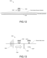
- FIG. 13 is a schematic of wave energy attenuation in multi-sensor-based surface wave detection, in accordance with an exemplary embodiment of the invention.
- FIG. 14 is a flowchart of mechanical wave-based damage detection of an integrated rapid infrastructure monitoring system, in accordance with an exemplary embodiment of the invention.
- FIG. 15 is a flowchart of a method for detecting corroded reinforcement, in accordance with an exemplary embodiment of the invention.
- FIG. 16 is a schematic, top view showing a pluralized double-sided bounce impacting system, in accordance with an exemplary embodiment of the invention.
- FIG. 17 is a schematic, side view of a circular rolling impact system, in accordance with an exemplary embodiment of the invention.
- FIG. 18 is a schematic, side view of a spiral rolling impact system, in accordance with an exemplary embodiment of the invention.
- FIG. 19 is a flowchart of using a bounce impact system, in accordance with an exemplary embodiment of the invention.
- FIG. 20 is a flowchart of using a circular or spiral rolling impact system, in accordance with an exemplary embodiment of the invention
- FIG. 21 is a top view of a test scan area, in accordance with an exemplary embodiment of the invention.
- FIG. 22 shows image detected surface damage, in accordance with an exemplary embodiment of the invention.
- FIG. 23 A is a 2-D energy intensity colormap, in accordance with an exemplary embodiment of the invention.
- FIGS. 23 B- 23 D are a delamination map, a corrosion map, and a vertical crack map, respectively, in accordance with an exemplary embodiment of the invention.
- FIGS. 24 A- 24 B show a 2-D cross-sectional view and a 3-D perspective view, respectively, of an ultrasonic tomography scanning result of the indicated area in FIG. 23 B , in accordance with an exemplary embodiment of the invention
- FIG. 25 is a perspective view of an integrated rapid cylindrical infrastructure monitoring system, in accordance with an exemplary embodiment of the invention.
- FIGS. 26 A and 26 B show the system of FIG. 25 in situ and an exemplary scanning result, respectively, in accordance with an exemplary embodiment of the invention.
- the present invention in some embodiments thereof, relates to infrastructure maintenance and, more particularly, but not exclusively, to systems for assessing infrastructure maintenance needs.
- NDT non-destructive testing
- the automated crack evaluation (ACE) system described herein aims to perform rapid, traffic disruption-free inspection of internal/external concrete structures, such as bridges, with enhanced scanning qualities leveraging the integrated scanning platform, advanced impacting system, and a multichannel acoustic sensing unit. It should also be understood that the presently described system could also be used for scanning other infrastructure besides roadways/bridges, such as pipes or tubes, buildings/construction, and the like. Furthermore, the system could be employed for assessment in non-infrastructure applications as well.
- the ACE system is configured with arrays of double-sided bounce impactors and micro-electromechanical system(s) (MEMSs) for conducting infrastructure inspection.
- MEMSs micro-electromechanical system
- the inspection can include detecting delamination, vertical cracks, and/or corroded reinforcement, impact-echo testing, wave scattering, wave attenuation, LIDAR and/or GPR sensing methods, respectively.
- the ACE system described herein includes at least one of an advanced auto-impacting system, a multichannel acoustic scanning unit, and an integrated scanning platform.
- FIG. 1 is a block diagram of an integrated rapid infrastructure monitoring system 100 , in accordance with an exemplary embodiment of the invention.
- the ACE system 100 includes at least one of an advanced auto-impacting system 102 , a multichannel acoustic scanning system 104 , an integrated scanning platform 106 , and at least one controller/processor 108 , for example for image and sensor readings processing and/or including software and/or software programming for performing same.
- FIG. 2 A is a schematic, top view of a double-sided bounce impacting (DSBI) system 200 , in accordance with an exemplary embodiment of the invention.
- DSBI double-sided bounce impacting
- the DSBI system 200 is an exemplary embodiment of the advanced auto-impacting system 102 , however, other impacting systems besides the DSBI system 200 could be used.
- this system 200 is called “double-sided” because the impactor 202 (shown as a ball shape in FIG. 2 A ) can be swung from one side (in a first direction, for example counter-clockwise) to the other, such as shown in FIG. 2 C , using an actuator 204 , such as a DC motor, and then back again (in a second direction, opposite the first direction, for example clockwise).
- an actuator 204 such as a DC motor
- the impactor 202 is connected to the actuator 204 using a cable or wire 206 , for example a 0.063′′ piano wire (ASTM A228), optionally where the cable 206 is springy or resilient or has high elasticity.
- a cable or wire 206 for example a 0.063′′ piano wire (ASTM A228), optionally where the cable 206 is springy or resilient or has high elasticity.
- Exemplary wire 206 spring-back multipurpose 304 stainless steel wire, can be procured from McMaster-Carr at www.mcmaster.com/piano-wire/.
- the wire is selected to be a certain diameter (e.g. less than 0.1′′ in diameter) to avoid certain resonance frequencies which may impact sensing quality.
- the impactor 202 is constructed at least partly of metal (e.g. steel) and/or carbon (e.g. a low-carbon steel ball).
- the actuator 204 has more than 180 degrees of rotation and is at least 1000 RPM in speed.
- FIGS. 2 B- 2 C are schematic, top and side views, respectively, of the DSBI system 200 system 200 in operation, in accordance with an exemplary embodiment of the invention.
- FIG. 2 B shows the “double-sided” nature of the impact system 200 in an embodiment of the invention, wherein the actuator 204 of the system 200 causes the impactor 202 to switch back and forth between a first configuration 202 ′ and a second configuration 202 ′′, around a common rotational axis 208 , such as shown in more detail in FIG. 2 C .
- the DSBI system 200 transitions between the first configuration 202 ′ and the second configuration 202 ′′ at least partly by bouncing the impactor 202 against an underlying surface 210 and utilizing the rebounding force to change direction of movement of the impactor 202 (i.e. actuator movement is assisted by the bouncing force (or vice versa) or bouncing force is an alternative to actuator movement).
- the underlying surface 210 could be virtually any form, wherein the ACE system 100 is configured to scan appropriately the underlying surface 210 based on, as examples, shape or material type(s). Exemplary shapes could be more or less flat or planar like a roadway or a bridge deck (such as shown and described with respect to FIGS.
- FIG. 2 B shows how the actuator 204 and/or the bouncing force of the impactor 202 causes the impactor 202 to switch back and forth between right and left in the Figure.
- the second configuration 202 ′′ is opposite or nearly opposite the first configuration 202 ′.
- the first configuration 202 ′ and second configuration 202 ′′ are opposite or nearly opposite of each other in a rotational sense, for example at about 2-4 o'clock and about 8-10 o'clock, respectively, such as shown in FIG. 2 C .
- the rotational range of motion is larger or smaller than described above.
- Advantages of such a system include a wide angle of motion (for generation of a strong impact signal such as a high amplitude mechanical wave) and/or a high rate of impact as the combination of actuator force and bouncing impactor 202 force, instigating movement in the opposite direction of the DSBI system 200 , results in an extremely rapid and consistent PRF.
- the system 200 provides up to 3-4 impacts/second/impactor when in operation.
- the system 200 provides an even faster rate.
- the system 200 provides a slower rate, for example, when the system 200 includes multiple impactors 202 , such as shown and described with respect to FIGS. 3 , 9 - 11 , 14 , 16 , 17 and 21 - 24 , inter alia.
- FIG. 3 is a schematic layout 300 of an integrated rapid infrastructure monitoring system 100 showing a multichannel acoustic scanning (MAS) unit 300 during three consecutive impacts 310 , 320 , 330 , in accordance with an exemplary embodiment of the invention.
- the DSBI system 200 provides high incident wave energy and/or generates constant and high PRF mechanical waves, for example, at least 2-4 times what is typically generated by a single sided bounce system.
- a MAS unit 300 is deployed which combines multiple DSBI systems and MEMS sensors.
- the exemplary MAS unit 300 includes 9 DSBI systems 200 and 22 MEMS sensors 302 with 30 cm and 10 cm spaces between them, respectively. It should be understood that more or less DSBI systems 200 and/or more or less MEMS sensors 302 could be used in the MAS unit 300 .
- each DSBI system 200 operates with 20-millisecond time intervals to avoid wave interference by the simultaneous impact.
- at least one of the plurality of DSBI systems 200 is designed to avoid motion path interference with any adjacent DSBI systems 200 /impactors 202 , for example, the DSBI systems 200 being alternatively offset from each other, such as shown in FIG. 3 , where every other DSBI system 200 is set forward or back from the next.
- the three consecutive impacts 310 , 320 , 330 shown in FIG. 3 can be defined (x i , t i ), (x i+1 , t i+1 ), and (x i+2 , t i+2 ) by time (t) and distance (x) with the impact number (i).
- the impacting points (IPs) are located at MEMS 1, 4, 7, 10, 13, 16, 19, and 22.
- s m is the section between m th MEMS and (m+1) th MEMS.
- the distance and range of the impact point and sections, IP and s facilitate determining the resolution of the final result maps (exemplars of which are shown with respect to the Example, below) for detecting the delamination and vertical crack.
- the resolution in longitudinal direction depends at least partly on the impact location, which is determined by vehicle speed (the ACE system 100 is towed and/or carried by a vehicle, in an embodiment of the invention) and PRF.
- the pulse repetition time of the developed DSBI system 200 is 400-milliseconds, in some embodiments of the invention. It should be understood that the PRF could be more or less.
- the 9-DSBI, MAS system 300 shown in FIG. 3 with a 20-millisecond delay provides 20 impacts per second.
- the ACE system 100 can provide an even faster rate with an additional MAS unit installed in parallel, generating a mechanical wave every 200-milliseconds, which is similar to PRF of low-frequency ultrasonic transducers (40 impacts per second by the 18-DSBI system).
- the number of MAS units is scalable upwards, in some embodiments of the invention.
- FIG. 4 shows an automated height adjustable scanning (AHAS) platform 400 , usable as the integrated scanning platform 106 in an embodiment of the invention, including at least one of mechanical wave (DSBI), acoustic scanning (MEMS), electromagnetic wave (GPR), video image, and/or position data (GPS) collection capability, in accordance with an exemplary embodiment of the invention.
- the adjustable scanning-height design allows a nonstop, rapid traffic (e.g. up to or exceeding highway speeds) operation of the ACE system 100 by being carried on and/or being towed behind a vehicle, including multiple scanning paths or lanes for rapid and traffic-disruption-free inspection of infrastructure, for example, a roadway or bridge.
- the AHAS platform 400 comprises a frame elevation system 402 , a MAS unit 300 (including at least one impactor frame 404 and at least one sensor frame 406 ), optionally at least one GPR antenna 408 , optionally at least one GPS antenna 410 , at least one image sensor 412 (e.g. a video camera), at least one encoder, a controller/processor 414 and/or a control box 416 (for example, for the controlling operation of the AHAS or one or more of the components included thereon and/or comprising the ACES System 100 ).
- a MAS unit 300 including at least one impactor frame 404 and at least one sensor frame 406 ), optionally at least one GPR antenna 408 , optionally at least one GPS antenna 410 , at least one image sensor 412 (e.g. a video camera), at least one encoder, a controller/processor 414 and/or a control box 416 (for example, for the controlling operation of the AHAS or one or more of the components included thereon and
- FIG. 5 is a perspective view of the automated height adjustable scanning platform 400 , in accordance with an exemplary embodiment of the invention.
- the AHAS platform 400 comprises of four linear actuators 502 for raising and/or lowering the AHAS platform 400 during operation. It should be understood that there could be more or less linear actuators.
- the linear actuators 502 have a 20 cm stroke length and 1 cm/s increase speed.
- FIGS. 7 A and 7 B show the AHAS platform 400 in a high and low-level position, respectively.
- the height-adjustable frame 400 is designed to avoid damage to elements of the ACE System 100 by bumping into the underlying surface 210 and/or other structures (e.g., bridge deck, ground, median strip, sidewalk) during the inspection.
- FIGS. 6 A- 6 C are images of the AHAS platform 400 system, in accordance with an exemplary embodiment of the invention.
- FIG. 6 A shows an embodiment with a frame 602 operatively connected to diagonal frame elements 604 which, when the diagonal frame elements 604 are actuated (by at least one actuator, not shown) cause the frame 602 to raise or lower as the diagonal frame elements move along a track 606 .
- FIG. 6 B shows an embodiment with the frame 602 operatively connected to vertical frame elements 614 which, when actuated by actuators 502 , cause the frame to raise or lower as the vertical frame elements 614 move vertically along a track 616 .
- the vertical frame elements 614 are also movable horizontally on a horizontal track 618 .
- both diagonal frame elements 604 and vertical frame elements 614 are used in combination, with one or both being actuated (for example by actuators 502 ).
- actuation of the diagonal and/or vertical frame elements is in response to distance detection, detecting the distance, between the MAS unit 300 , and its associated frames 404 , 406 , and the underlying surface being scanned, such as a bridge deck or a roadway.
- a controller is included in the system 100 which, as a part of its operative tasks, automatically adjusts the height of the a MAS unit 300 , by moving the frames 404 , 406 , based on sensed data from a distance sensor optionally in combination with an entered value for desired distance between the sensor array (and/or frame) and the underlying surface 210 being scanned.
- a laser distance sensor is used for this purpose.
- the system 500 is controlled by a software-programmed controller, such as described elsewhere herein.
- FIGS. 7 A- 7 B are side perspective views of an automated height adjustable scanning platform 400 raised and lowered, respectively, in accordance with an exemplary embodiment of the invention. It should also be understood that various structures of the ACE System 100 can be configured to be foldable or contractible in order to save space during transport, storage, or even during use, for example, when not all of the sensing systems available need to be utilized.
- FIG. 8 is top perspective view of a multichannel acoustic scanning array 800 , comprising a plurality of MEMS sensors 302 with sound insulation 802 , in accordance with an exemplary embodiment of the invention.
- the sound insulation 802 reduces noise generated by traffic and/or a vehicle towing or bearing the ACE system 100 so that sensing of impacts on the underlying surface by the multichannel acoustic scanning array 800 of the at least one impactor 202 (for example, as employed in a DSBI) is performed at higher quality and/or clarity.
- FIG. 9 is a timeline 900 of an infrastructure scanning procedure for various components of the ACES system 100 , in accordance with an exemplary embodiment of the invention.
- the AHAS platform 400 remotely controls the MAS unit 300 level to a lower position (for example, as shown in FIG. 7 B ) while the ACE system 100 approaches the bridge (or other infrastructure, as the underlying surface 210 ) starting point.
- the low-level position provides a proper lift-off distance between the DSBI system 200 and the bridge deck surface to generate a mechanical wave.
- the DSBI system 200 also starts impacting while the MAS unit 300 is lowered to the scanning level (about 10 cm, in some embodiments).
- the ACE system 100 allows for continuous movement and rapid inspection without preparation time.
- the MAS unit 300 After the MAS unit 300 reaches the lower position, some or all of the scanning and scanning-related devices (e.g., MEMS sensors 302 , GPR 408 , GPS 410 , encoders, and video 412 ) start collecting data.
- the ACE system 100 passes the end of the bridge 210 , at least one of the DSBI, MEMS sensors, encoders, and GPR turn off.
- the AHAS platform 400 optionally lifts the MAS unit 300 after the scanning devices stop recording data.
- the ACE system 100 proceeds to inspect the next lane, if necessary.
- the GPS and video camera run the entire inspection time without interruption. Optionally, one or both run less than the entire time.
- FIG. 10 is a block diagram of an exemplary configuration of an integrated rapid infrastructure monitoring system 1000 (system 1000 is an exemplary embodiment of an ACE system 100 ), in accordance with an exemplary embodiment of the invention.
- the multiple processes of the integrated rapid infrastructure monitoring system 1000 are classified by functions and/or purposes such as signal obtaining/generating and scan positioning.
- Process-1 comprises at least one MEMS sensor 1002 , data acquisition hardware (DAQ) 1004 , and at least one laptop 1006 to measure the mechanical wave generated by the DSBI system 1010 impacting the bridge deck.
- Process-2 comprises the DSBI system 1010 including motor 1010 ′, motor drive 1010 ′′, and computing platform 1010 ′′′ to generate the mechanical wave on the bridge deck.
- Process-3 comprises at least one GPR antenna 1020 and at least one controller 1022 to collect the EM waves.
- Process-4 comprises at least one GPS 1030 and radio antenna 1032 , GPS board 1034 , encoder 1036 , computing platform 1038 , and laptop 1040 to record the position of the integrated rapid infrastructure monitoring system 1000 .
- Real-time kinematic (RTK) GPS provides a centimeter-level accuracy by correcting the position with the reference from the base station 1050 .
- FIG. 11 is a schematic diagram of the integrated rapid infrastructure monitoring system 1000 in operation, in accordance with an exemplary embodiment of the invention.
- the configuration of integrated rapid infrastructure monitoring system 1000 illustrates an exemplary detailed operation of Process 1 and 2 (MEMS sensor and DSBI, shown in FIG. 10 ) for detecting delamination and vertical cracks in the scanned infrastructure.
- MEMS sensor and DSBI Process 1 and 2
- twenty-two noncontact MEMS sensors 1002 are placed in sound insulation forms (such as shown in FIG. 8 ) to minimize or prevent wholly external direct acoustic waves and noises.
- the sound insulation is placed between the bottom surface of the sensor frame 406 and MEMS sensors to reduce any unexpected vibrations transferred from the various frames used in the system, for example, the AHAS platform 400 itself, the at least one impactor frame 404 and the at least one sensor frame 406 .
- the arrows shown in FIG. 11 indicate the direction of the obtained mechanical waves for infrastructure damage/crack detection.
- the arrows illustrate surface wave propagation.
- the arrow pointing directly upwardly represents the mechanical wave generated by the DSBI to obtain the flexural mode over the delamination area.
- FIG. 12 is a schematic 1200 of using an air-coupled MEMS sensor 1202 detecting flexural vibration 1206 to identify delamination 1204 , in accordance with an exemplary embodiment of the invention.
- Exemplary damage identification processes for monitoring delamination, vertical crack, and corroded reinforcement detection are described hereinbelow.
- MAS unit 300 based and GPR 408 based scans are addressed with a fundamental approach and a post-processing procedure, in an embodiment of the invention.
- the process includes the post-processing procedure, details of data status (e.g., size or format), parameters (e.g., cutoff frequency, processed target range), and expected outputs.
- the MAS unit 300 based approach optionally includes impact-echo and/or wave attenuation techniques to identify the delamination and vertical crack.
- the impact-echo test has two different families of frequency modes: the thickness and the flexural vibration modes.
- the thickness mode (f TM ) is dominant when body waves are repetitively reflected between the two parallel boundaries.
- the thickness mode is commonly used to estimate the thickness of the medium with known longitudinal wave velocity.
- the flexural vibration mode can present the delamination since it occurs by the out-of-plane vibration of the concrete above a delamination.
- the flexural vibration mode for detecting delamination implements the impact-echo test, the schematic of which is shown in FIG. 12 , in an embodiment of the invention.
- multiple noncontact MEMS sensors 1202 are used to collect the leaky-wave signals.
- f FM k DF 2 ⁇ ⁇ 2 ⁇ h 2 ⁇ D ⁇ ⁇ h , ( 1 )
- k DF is a dimensionless frequency which is determined from the general natural frequencies in terms of the width-to-depth ratio of delamination
- h is a depth of delamination
- ⁇ is material density.
- the flexural vibration mode depends on the geometrical property of k DF and h by given material properties.
- the shape of delamination e.g., width, depth
- EI energy intensity
- EI n (f ) energy intensity of n th MEMS sensor
- ⁇ n (f) is the spectral energy density of n th MEMS sensor
- ⁇ n (f)
- f l and f h are the low and high-boundary frequency (i.e., 1 kHz and 6 kHz in our system).
- the obtained EI related to flexural vibration mode is processed to create a two-dimensional (2-D) scanning image, or 2-D colormap, presenting delamination.
- the 2-D colormap is obtained by interpolating the 2-D matrix (obtained EIs) in a spatial meshed grid by x and IP.
- FIG. 23 A is representative of a 2-D colormap obtained using Eq. (2). All-post-processing can be performed with MATLAB mathematical computing software (MathWorks, Natick, Mass., USA) or other suitable software.
- FIG. 13 is a schematic 1300 of detecting wave energy attenuation 1304 using the ACE system 100 , in accordance with an exemplary embodiment of the invention.
- Using a MAS unit 300 scan allows for sensing wave attenuation for vertical crack 1306 detection, in an embodiment of the invention.
- wave attenuation causes signal amplitude to become lower when traveling through the medium with damage (e.g., vertical cracks 1306 ).
- the surface wave attenuation is obtained from multiple receivers by calculating the wave energy difference between two adjacent receivers 1302 ′, 1302 ′′, such as shown in FIG. 13 .
- the ACE system 1300 shown in FIG. 13 uses multiple MEMS sensors 1302 ′, ii, n, to detect the attenuated surface waves 1304 ′′ which are resultant from a crack in the scanned infrastructure, such as a bridge deck.
- the attenuated wave 1304 ′′ is calculated from the difference in wave energies detected by adjacent MEMS sensors between the original, un-attenuated wave 1304 ′ and the attenuated wave 1304 ′′.
- the wave energy of n th MEMS (E n ) can be expressed as,
- w n (t) is obtained signal from n th MEMS across concrete
- T s and T e are start and end of the time window.
- the wave energy is calculated with a time window ( ⁇ 0.3-millisecond) to detect only mechanical wave energy dominating before the direct acoustic wave 1308 arrival from the impact point (0.35 millisecond).
- the attenuated wave energy can be expressed by the percentage decrease between two energies calculated from two adjacent MEMS sensors 1302 ′, 1302 ′′: E n1 represents the wave energy of the n1 th MEMS sensor from the impacting point; E n2 represents the wave energy of the n2 th MEMS sensor from the impacting point. The n1 MEMS should be closer to the IP than n2 to obtain the positive energy loss (EL) value.
- the obtained wave energy will be processed to a 2-D colormap, presenting the vertical cracks.
- a post-processing algorithm, according to an embodiment of the invention is presented in the flowchart, as depicted in FIG. 14 , below.
- Data collection and storage is optionally processed by the LabView software (National Instruments, Austin, Tex., USA) or other similarly functioning software.
- data collection is performed with a 0.5 M/s sampling rate in “streaming” mode.
- the streaming mode records and transfers data to a computer in real-time.
- the obtained data from three DAQs are combined into one matrix (inspection time ⁇ 22-channel output).
- the post-processing for the delamination detection is conducted with the wave response obtained from MEMS sensors at the f (i.e., MEMS 1, 4, 7, 10, 13, 16, 19, and 22 in FIG. 3 ), which is placed at the closest location from the impacting point, IP.
- the identified delamination areas are presented on a 2-D colormap by calculating the sum of power spectrum as the band energy (1 kHz to 6 kHz band) as described with respect to FIG. 12 .
- the 2-D colormap of vertical crack detection is presented from the data set of the calculated wave attenuation of each section, s 1 to s 21 in FIG. 3 .
- FIG. 14 is a flowchart 1400 of mechanical wave-based damage detection method using the integrated rapid infrastructure monitoring system 1000 , in accordance with an exemplary embodiment of the invention.
- the process demonstrated by the flowchart 1400 illustrates obtaining mechanical waves which are processed to present a delamination map and a vertical crack map.
- flowchart 1400 corresponds to the specific embodiment shown in FIGS. 10 and 11 , however, other configurations (e.g. more or less impactors, more or less MEMS sensors, more or less DAQs, more or less computers) could be used with a substantially similar or identical process flow as is shown.
- FIG. 14 starts 1402 where the DSBI system is activated 1404 , optionally at a preset time delay 1406 (in this scenario, with a 20 ms delay), whereby when the impactors of the DSBI strike the underlying surface acoustic waves are generated. These acoustic waves are then detected 1408 by the MEMS sensors of the integrated rapid infrastructure monitoring system 1000 .
- the impacts sensed by the MEMS sensors are routed 1410 ′, 1410 ′′, 1410 ′′′, to a plurality of DAQS for processing (in this scenario, three DAQs are shown, like in FIG. 11 ). From these different DAQs, a comprehensive data set is created through combining 1412 them from the DAQ output data.
- the sensed impacts are processed 1414 , for example including applying 1416 a band pass filter, and wherein the processed impact data is then separated into a data set for delamination detection 1418 and a data set for vertical crack detection 1420 .
- Additional processing 1422 optionally occurs for the delamination data set, including at least one step of performing a fast Fourier transform 1424 , summing power spectrum for band energy 1426 , applying position information from encoder data 1428 , and creating/displaying a 2-D interpolated color map 1430 , to generate 1432 a delamination map.
- Additional processing 1434 optionally occurs for the vertical crack data set, including at least one step of calculating energy loss between MEMS sensors 1436 , applying position information 1438 , displaying a 2-D interpolated map 1440 , and generating 1442 a vertical crack map.
- FIG. 15 is a flowchart 1500 of a method for detecting corroded reinforcement, in accordance with an exemplary embodiment of the invention.
- the intensity of a reflected GPR EM wave from the reinforcement structures within the infrastructure being scanned (e.g. within a bridge deck) and its arrival time presents the reinforcement condition/status.
- the depth of the reinforcement is obtained by using the two-way travel time (TWTT) of the EM wave generated by the GPR.
- the collected EM wave is normalized 1502 by a direct coupling wave, in an embodiment of the invention.
- the direct coupling is the first pulse on the GPR signal. Since the direct coupling wave influences the entire wave response, the obtained wave amplitude is normalized by the direct coupling wave amplitude (A dc ). From the normalized A-scan data, the normalized peak amplitude of reinforcement reflection and TWTT of the peak point are obtained. The TWTT is converted to depth with the EM wave speed.
- the obtained 1504 normalized amplitude and depth of the reinforcements are presented on a scatter plot to observe and show the relationships between the amplitude and depth.
- a 90 th percentile linear regression line is calculated 1506 from the scattered data to perform depth correction.
- the depth correction is performed 1508 to eliminate depth-dependent amplitude effects by subtracting the regression line from the amplitudes.
- the depth-corrected amplitude presents the reinforcement corrosion.
- the obtained depth-corrected amplitudes will be presented 1510 by a 2-D colormap, such as described with respect to FIG. 14 (delamination detection) and the Example.
- FIG. 16 is a schematic, top view showing a pluralized double-sided bounce impacting system 1600 , in accordance with an exemplary embodiment of the invention.
- the pluralized system 1600 comprises a plurality of double-sided bounce impact systems 200 .
- Using a plurality of systems 200 provides an extremely high number of impacts to scan an underlying surface, such as road pavement or a bridge.
- system 1600 provides 10 to 30 impacts per second, which allows for a 50 to 60 mph speed inspection environment. It should be recalled that one of the disadvantages of the current impact measurement systems is the extremely slow speed at which measurements must be taken, this problem being solved by using an impact system such as pluralized double-sided bounce impacting system 1600 .
- the scan can be of high quality as a result of the high resolution data provided by the massive amounts of impacts generated and then measured by system 1600 .
- system 1600 is arranged with alternating, facing impactors, virtually any pluralized arrangement of impactors is usable with the ACE system 100 , with the understanding that generally speaking, more impactors provides a higher resolution result as long as their impact timing is carefully controlled.
- FIG. 17 is a schematic, side view of a circular rolling impact system 1700 , in accordance with an exemplary embodiment of the invention.
- at least one impactor 1702 is spun about an axis of rotation (optionally an axis of a disk or wheel 1704 ), causing the one or more impactors 1702 to strike the underlying surface 1708 in sequence.
- the impactors rotate outside the maximum diameter of the wheel, when the wheel rotates around the axis of rotation, to enable the impactors to impact on the underlying surface during system 1700 operation.
- the axis of rotation (central rotational axis of the system 1700 ) is an axle of a vehicle on which the system 1700 is mounted, such that when the vehicle is in motion, the axle turns, thereby causing the at least one impactor 1202 to impact on the underlying surface on which the vehicle is traveling.
- the impactors 1702 are connected to the wheel at or near the axis of the wheel 1704 .
- the PRF can be increased or decreased, optionally by altering the speed of the spinning about the axis (i.e. by speeding up or slowing down the vehicle) and/or by increasing or reducing the number of impactors on the wheel 1704 .
- At least one sensor 1706 is used to detect the impacts for data accumulation.
- more than one wheel 1704 with at least one impactor 1702 is used in the system 1700 .
- FIG. 18 is a schematic, side view of a spiral rolling impact system 1800 , in accordance with an exemplary embodiment of the invention.
- system 1800 notably, but not exclusively, differs from system 1700 in the arrangement of the impactors 1802 on the wheel 1804 , wherein the impactors 1802 are connected to the wheel 1804 in a circular pattern which causes a spiraling behavior of the impactors 1802 as the wheel 1804 is turned.
- there is only one impactor 1802 attached to the wheel 1804 rather than a plurality.
- impact rate on the underlying surface 1808 can also be adjusted by adding or removing impactors 1802 from the wheel and/or changing their configuration on the wheel 1804 (rather than, or in combination with, adjusting forward velocity of the system 1800 ).
- more than one wheel 1804 with at least one impactor 1802 is used in the system 1800 .
- FIG. 19 is a flowchart 1900 of using a DSBI 200 , in accordance with an exemplary embodiment of the invention.
- the system starts with movement ( 1902 ) of an impactor, as examples, those described herein, from a first configuration and in a first direction towards a second configuration.
- movement is achieved through actuated movement, for example from a motor.
- movement is achieved through the use of bouncing force, for example if the impactor is rebounding from a previous impact with an underlying surface.
- This movement ( 1902 ) phase ends when the impactor is impacted ( 1904 ) in the second configuration, in some embodiments of the invention.
- the impacting ( 1904 ) is measured ( 1906 ) by at least one sensor, optionally an array of sensors.
- a second movement phase occurs where rapid lift-up of the impactor by the actuator and/or bounce force (from the impacting ( 1904 )) moves ( 1908 ) the impactor in a second direction, opposite the first direction, from the second configuration towards the first configuration.
- the end of this second movement phase is triggered by impacting ( 1910 ) the impactor on the underlying surface in the first configurations.
- measurement ( 1906 ) of impact data from impact ( 1910 ) in the first configuration is optionally conducted.
- the movement and impacting cycle ( 1902 - 1910 ) is repeated ( 1912 ) for conducting additional measuring ( 1496 ) and accumulation of data.
- this cycle is used for a plurality of impact systems (such as in systems 200 , 300 , 1000 ) for the measurement and accumulation of enhanced amounts of impact data in relation to using just a single impact system 200 .
- enhanced impact numbers and thus, measurements
- PRF can be altered by adjusting the speed of the actuator or actuators in the system 200 , 300 , 1000 , in some embodiments of the invention.
- ACE system 100 in combination with at least one of acoustic scanning (MEMS), electromagnetic wave (GPR), video image, and/or position data (GPS) collection.
- MEMS acoustic scanning
- GPR electromagnetic wave
- GPS position data
- FIG. 20 is a flowchart 2000 of using a circular or spiral rolling impact system 1700 , 1800 , in accordance with an exemplary embodiment of the invention.
- the system 1700 , 1800 is provided with linear movement over the underlying surface being scanned (typically forward movement, although could be reverse) causing rotation ( 2002 ) of a wheel to which at least one impactor is attached.
- rotation ( 2002 ) of a wheel to which at least one impactor is attached As the wheel rotates ( 2002 ), the at least one impactor is imparted with motion about a central axis of the wheel, causing the impaction ( 2004 ) of the impactor on the underlying surface.
- impact data is measured ( 2006 ) by at least one sensor, optionally by a sensor array.
- the rate of impacting ( 2004 ) is adjusted ( 2008 ) by performing one or more of increasing or decreasing the velocity of the overall system (e.g. if it is mounted on a trailer being pulled by a vehicle or mounted on a vehicle), modifying the number of impactors, and/or modifying the configuration of impactors on the wheel.
- ACE System 100 optionally in combination with at least one of acoustic scanning (MEMS), electromagnetic wave (GPR), video image, and/or position data (GPS) collection.
- MEMS acoustic scanning
- GPR electromagnetic wave
- GPS position data
- hardware for performing selected tasks such as reading, storing, processing, and/or outputting data from at least one of acoustic scanning (MEMS), electromagnetic wave (GPR), video image, and/or position data (GPS) collection individually and/or in combination could be embodied in a computer/controller.
- Hardware for performing selected tasks, such as described herein, could be implemented as a chip or a circuit, optionally as a part of a computer/controller.
- selected tasks according to embodiments of the invention could be implemented as a plurality of software instructions being executed by a computer/controller using any suitable operating system.
- a data processor such as a computing platform for executing a plurality of instructions.
- the data processor includes a volatile memory for storing instructions and/or data and/or a non-volatile storage, for example, a magnetic hard-disk and/or removable media, for storing instructions and/or data.
- a network and/or communication connection is provided as well.
- a display and/or a user input device such as a keyboard or mouse are optionally provided as well.
- FIG. 25 is a perspective view of an integrated rapid cylindrical infrastructure monitoring system 2500 , as an exemplar of an ACE system 100 , in accordance with an exemplary embodiment of the invention.
- the ACE system 100 does not have to be used on a flat or substantially flat underlying surface 210 .
- the ACE system 100 is adapted/configured for use with a curved or rounded underlying surface, such as a pipe 2600 (shown in more detail with respect to FIG. 26 A ), using the integrated rapid cylindrical infrastructure monitoring system 2500 .
- the integrated rapid cylindrical infrastructure monitoring system 2500 comprises at least one of an auto-impacting system 2502 , sensors 2504 (e.g. non-contact and/or MEMS), wheels 2506 , and shock absorbers 2508 .
- the shock absorber(s) 2508 and wheels 2506 are designed to provide consistent distances between sensors and the underlying surface 2600 (lift-off distance), for example using the springy nature of the shock absorbers to compress or extend depending on the varying diameter of the pipe as the system 2500 passes through it.
- the shock absorbers can accommodate diameter changes of ⁇ 5 cm.
- the range of motion of the shock absorbers is 2508 more or less than ⁇ 5 cm.
- different shock absorbers 2508 are used for different pipe sizes, and are modular and/or interchangeable.
- the auto-impacting system 2502 is operated by a motor and is designed to generate consistent and maximized mechanical wave amplitude in a inhomogeneous material or materials of the underlying surface. It should be understood this system 2502 can use a DSBI system and/or motor, such as described elsewhere herein, and functions in a similar fashion. That is, flipping from one side to the other, optionally using a bouncing force as an impetus to motion of the impactor. Representative advantages of the system 2500 are providing high impact force to increase a signal-to-noise ratio on inhomogeneous concrete and allowing a rapid and consistent PRF for high-speed inspection.
- the impactor is substantially spherical and is designed with a 12 mm low-carbon steel ball and high elastic stainless-steel wire, entirely avoiding or dampening additional resonance frequency noises.
- other sensors such as LIDAR, GPR, and/or GPS are used system 2500 .
- FIGS. 26 A and 26 B show the system 2500 of FIG. 25 in situ in a pipe 2600 and an exemplary scanning result, respectively, in accordance with an exemplary embodiment of the invention.
- the system 2500 crawls/rolls through the pipe 2600 wherein the auto-impacting system 2502 is afforded the ability to impact on the inner surface of the pipe 2600 as the system 2500 moves.
- sensed data is conveyed to at least one controller/processor and/or other hardware for processing and/or analysis.
- An example of such analysis output is shown in FIG. 26 B .
- FIG. 21 is a top view of a test scan area 2100 including a bridge deck 2102 as the underlying surface being scanned for defects, in accordance with an exemplary embodiment of the invention.
- the bridge deck 2102 was a 95 m long and 13.5 m wide concrete bridge in Texas, United States. Inspection of the bridge deck 2102 was performed using an ACE system 100 , more specifically, the integrated rapid infrastructure monitoring system 1000 shown and described with respect to FIGS. 10 , 11 . This bridge was constructed in 1972 and had two lanes that carry two-way traffic. The integrated rapid infrastructure monitoring system 1000 was used to cover the 95 m long length and 8 m width of the bridge deck 2102 in 4 separate, 2 m wide, scanning paths, see P1-P4 in FIG. 21 .
- the integrated rapid infrastructure monitoring system 1000 utilized the MAS unit 300 , including the plurality of DSBI systems and MEMS sensors, for evaluating delamination and vertical crack defects in the bridge deck 2102 .
- the system 1000 also utilized GPR for identifying reinforcement corrosion within the bridge deck 2102 structure.
- FIG. 22 shows several surface defects from the recorded video images.
- 3-D ultrasonic tomography scanning was performed in 10 different locations to compare obtained data.
- the inspection results provided information on the severity of delamination, vertical crack, and reinforcement corrosion as demonstrated in the generated 2-D energy intensity (EI) map shown in FIG. 23 A .
- the 2-D EI map is created using post-processing calculations.
- the 2-D EI colormap is obtained by interpolating a 2-D matrix in a spatial meshed grid.
- the 2-D matrix for the colormap is the EI matrix calculated by Eq. (2), described above with respect to FIG. 12 .
- the severity factors are calculated to the ratio of the delamination area EI to intact area EI to present the wave response change by delamination (i.e., severity factors of good, moderate damage, and severe damage condition: 5, 7.8, and 9).
- the present methodology uses the 2-D EI colormap, which is based on the sum of spectral magnitude as EI, to present the detected delamination rather than what would be typically used or indicated by common wisdom in the industry, that is, the magnitude of peak frequencies (using a 2-D transparent colormap instead).
- FIGS. 23 B- 23 D are a delamination map, a corrosion map, and a vertical crack map, respectively, generated in the course of the Example scanning procedure, in accordance with an exemplary embodiment of the invention.
- the 2-D EI colormap of FIG. 23 A presents the zoomed-in part of the red circle of “Area 4” shown in FIG. 23 B .
- This part is one example of the high-EI area with a 1.2 m ⁇ 2 m delamination size. Based on the fact the surface image around the area shows no surface damage, this area presents only internal delamination.
- the reinforcement corrosion map presents the corroded reinforcement locations and corrosion levels by calculating the depth-corrected normalized amplitude (NA) of EM waves according to the post-processing procedure shown and described with respect to FIG. 15 .
- Some delamination areas are found in the same location of the corroded reinforcement (e.g., “Areas 1-3”). Ultimately, these areas possibly reflect critical damage (e.g., potholes) due to the negative interaction as mentioned above.
- the vertical crack map displays the highest positive energy loss (EL) in the circled areas, as shown in FIG. 23 D .
- EL positive energy loss
- FIGS. 24 A- 24 B show a 2-D cross-sectional view and a 3-D perspective view, respectively, of an ultrasonic tomography scanning result of the indicated “Area 4” in FIG. 23 B , in accordance with an exemplary embodiment of the invention.
- ultrasonic tomography scanning is conducted.
- the scanned image shows both delamination and bridge deck thickness as the strong wave reflection (see cross-hatched area).
- the 3-D scanned area enables investigation of the delaminated and intact area, which is verified by the delamination of FIG. 23 B .
- scattered waves horizontal lining and vertical lining
- the ACE system 100 deploys the DSBI system, MAS unit, and AHAS platform to obtain high inspection quality regarding data collection resolution, wave energy, and consistent wave source.
- the high inspection quality is obtained by providing higher PRF, proper impact design, and high-resolution sensor deployment.
- compositions, method or structure may include additional ingredients, steps and/or parts, but only if the additional ingredients, steps and/or parts do not materially alter the basic and novel characteristics of the claimed composition, method or structure.
- a compound or “at least one compound” may include a plurality of compounds, including mixtures thereof.
- range format is merely for convenience and brevity and should not be construed as an inflexible limitation on the scope of the invention. Accordingly, the description of a range should be considered to have specifically disclosed all the possible subranges as well as individual numerical values within that range. For example, description of a range such as from 1 to 6 should be considered to have specifically disclosed subranges such as from 1 to 3, from 1 to 4, from 1 to 5, from 2 to 4, from 2 to 6, from 3 to 6 etc., as well as individual numbers within that range, for example, 1, 2, 3, 4, 5, and 6. This applies regardless of the breadth of the range.
Abstract
Description
-
- Existing or conventional impact sources or impactors provide inaccurate and unclean mechanical wave due to noises and their design. For example, chain impactors produce a clapping noise from each chain, and the existing impact machines experience resonance noise from impactor rods. That is, the vertical impactor naturally generates resonance frequency from the impactor (e.g., rod, regular hammer). The generated response noise can be very critical because it provides the wrong damage data.
- Most conventional systems cannot generate impact source data rapidly due to the nature of their design. The number of impacts is referred to as pulse repetition frequency (PRF). Low PRF causes a very slow speed scan (1 mph), additionally and/or alternatively, the low PRF causes poor resolution of data since high speed scans result in missing damage information. For this reason, most conventional system in use today are implemented in a manual, hand-operated cart.
where kDF is a dimensionless frequency which is determined from the general natural frequencies in terms of the width-to-depth ratio of delamination; h is a depth of delamination; D is flexural rigidity, D=Eh3/12 (1−v2), with Young's modulus (E) and Poisson's ratio (v); ρ is material density. Based on equation (1), the flexural vibration mode depends on the geometrical property of kDF and h by given material properties. Thus, the shape of delamination (e.g., width, depth) facilitates the determination the frequency of the flexural vibration mode. Due to the unknown geometry of delamination, many in the art would use a sum of spectral magnitude, or energy intensity, in a different range (e.g., 1.5 to 3 kHz (Hendricks et al. 2020), 1 to 4 kHz. However, the currently described process measures the flexural vibration mode by calculating the
EIn(f)=∫f
where EIn(f) is energy intensity of nth MEMS sensor; Ψn(f) is the spectral energy density of nth MEMS sensor, Ψn(f)=|Xn(f)|2, with a magnitude of the frequency component (Xn(f)); fl and fh are the low and high-boundary frequency (i.e., 1 kHz and 6 kHz in our system). The obtained EI related to flexural vibration mode is processed to create a two-dimensional (2-D) scanning image, or 2-D colormap, presenting delamination. The 2-D colormap is obtained by interpolating the 2-D matrix (obtained EIs) in a spatial meshed grid by x and IP.
where wn(t) is obtained signal from nth MEMS across concrete; Ts and Te are start and end of the time window. In an embodiment of the invention, the wave energy is calculated with a time window (˜0.3-millisecond) to detect only mechanical wave energy dominating before the direct
ELn1-n2=(E n1 −E n2)/E n1×100 (4)
The obtained wave energy will be processed to a 2-D colormap, presenting the vertical cracks. A post-processing algorithm, according to an embodiment of the invention is presented in the flowchart, as depicted in
-
- The developed DSBI system shows the high PRF and impact energy to detect delamination of different sizes by providing a sufficient incident wave to generate the flexural vibration mode. In addition, the sufficient incident wave allows the detection of vertical cracks by providing a proper surface wave propagation for measuring the wave attenuation.
- The MAS unit design allows 30 cm resolution for the delamination detection and 10 cm resolution for the vertical crack detection. These data collection resolutions help to obtain a high inspection quality and reliable inspection result by presenting the high resolution of the colormaps.
- The developed ACE system using the DSBI system and the AHAS platform achieve faster scanning speeds and a nonstop inspection system. These achievements significantly decrease the inspection time and increase safety by reducing the exposure of inspectors to live traffic. In addition, the post-processing process described herein provides clear, quantified damage ranges for the elimination of subjectivity.
- The adjustable frame design allows for ease of installation of the MAS unit. In addition, adding an additional MAS unit, an option described elsewhere herein, increases the data collection resolution by providing the additional MAS with the set of impacting and receiving.
Claims (20)
Priority Applications (1)
| Application Number | Priority Date | Filing Date | Title |
|---|---|---|---|
| US17/488,699 US11644380B2 (en) | 2020-09-29 | 2021-09-29 | Integrated rapid infrastructure monitoring systems and methods of using same |
Applications Claiming Priority (2)
| Application Number | Priority Date | Filing Date | Title |
|---|---|---|---|
| US202063084685P | 2020-09-29 | 2020-09-29 | |
| US17/488,699 US11644380B2 (en) | 2020-09-29 | 2021-09-29 | Integrated rapid infrastructure monitoring systems and methods of using same |
Publications (2)
| Publication Number | Publication Date |
|---|---|
| US20220099522A1 US20220099522A1 (en) | 2022-03-31 |
| US11644380B2 true US11644380B2 (en) | 2023-05-09 |
Family
ID=80822281
Family Applications (1)
| Application Number | Title | Priority Date | Filing Date |
|---|---|---|---|
| US17/488,699 Active US11644380B2 (en) | 2020-09-29 | 2021-09-29 | Integrated rapid infrastructure monitoring systems and methods of using same |
Country Status (1)
| Country | Link |
|---|---|
| US (1) | US11644380B2 (en) |
Families Citing this family (1)
| Publication number | Priority date | Publication date | Assignee | Title |
|---|---|---|---|---|
| US20230243959A1 (en) * | 2022-01-31 | 2023-08-03 | Gm Cruise Holdings Llc | Ground-penetrating radar sensors on vehicles for detecting underground features and road surface features |
Citations (5)
| Publication number | Priority date | Publication date | Assignee | Title |
|---|---|---|---|---|
| US20200096481A1 (en) * | 2017-06-06 | 2020-03-26 | Central Research Institute Of Building And Construction Co. Ltd. | Impact echo detection system |
| US20200300813A1 (en) * | 2017-02-24 | 2020-09-24 | Brigham Young University | Contact elements for acoustic excitation attached via a compliant material |
| US20210196409A1 (en) * | 2018-06-01 | 2021-07-01 | Steerable Instruments nv | Tool with torque-actuated end effector |
| US20210293306A1 (en) * | 2018-07-18 | 2021-09-23 | Mci (Mirror Controls International) Netherlands B.V. | Actuator |
| US20210310202A1 (en) * | 2020-04-01 | 2021-10-07 | Caterpillar Paving Products Inc. | Machine, system, and method for controlling rotor depth |
-
2021
- 2021-09-29 US US17/488,699 patent/US11644380B2/en active Active
Patent Citations (5)
| Publication number | Priority date | Publication date | Assignee | Title |
|---|---|---|---|---|
| US20200300813A1 (en) * | 2017-02-24 | 2020-09-24 | Brigham Young University | Contact elements for acoustic excitation attached via a compliant material |
| US20200096481A1 (en) * | 2017-06-06 | 2020-03-26 | Central Research Institute Of Building And Construction Co. Ltd. | Impact echo detection system |
| US20210196409A1 (en) * | 2018-06-01 | 2021-07-01 | Steerable Instruments nv | Tool with torque-actuated end effector |
| US20210293306A1 (en) * | 2018-07-18 | 2021-09-23 | Mci (Mirror Controls International) Netherlands B.V. | Actuator |
| US20210310202A1 (en) * | 2020-04-01 | 2021-10-07 | Caterpillar Paving Products Inc. | Machine, system, and method for controlling rotor depth |
Also Published As
| Publication number | Publication date |
|---|---|
| US20220099522A1 (en) | 2022-03-31 |
Similar Documents
| Publication | Publication Date | Title |
|---|---|---|
| Scott et al. | A comparison of nondestructive evaluation methods for bridge deck assessment | |
| Kudela et al. | Damage detection in composite plates with embedded PZT transducers | |
| Choi et al. | Application of ultrasonic shear-wave tomography to identify horizontal crack or delamination in concrete pavement and bridge | |
| Lim et al. | Combining multiple NDT methods to improve testing effectiveness | |
| Tosti et al. | An experimental-based model for the assessment of the mechanical properties of road pavements using ground-penetrating radar | |
| JP4938050B2 (en) | Ultrasonic diagnostic evaluation system | |
| Rose et al. | A guided wave approach to defect detection under shelling in rail | |
| Kohl et al. | Results of reconstructed and fused NDT-data measured in the laboratory and on-site at bridges | |
| Leng | Prediction of in-situ asphalt mixture density using ground penetrating radar: theoretical development and field verification | |
| Guthrie et al. | Automated air-coupled impact-echo testing of a concrete bridge deck from a continuously moving platform | |
| Shokouhi et al. | Nondestructive detection of delamination in concrete slabs: Multiple-method investigation | |
| US11644380B2 (en) | Integrated rapid infrastructure monitoring systems and methods of using same | |
| Larsen et al. | Automated sounding for concrete bridge deck inspection through a multi-channel, continuously moving platform | |
| Kang et al. | Rapid damage assessment of concrete bridge deck leveraging an automated double-sided bounce system | |
| Clem et al. | A consistent approach for processing and interpretation of data from concrete bridge members collected with a hand-held GPR device | |
| Takamine et al. | Efficient damage inspection of deteriorated RC bridge deck with rain-induced elastic wave | |
| Evani et al. | Air-coupled ultrasonic assessment of concrete rail ties | |
| Olson et al. | Concrete bridge condition assessment with impact echo scanning | |
| KR101791866B1 (en) | Cavity detection system for detecting cavity occurring in lower part of concrete track for railway | |
| JP2005331404A (en) | Method and apparatus for diagnosing reinforced concrete structure | |
| Simonin et al. | Detection of debonding and vertical cracks with non destructive techniques during accelerated pavement testing | |
| Shin et al. | How accurate is ground-penetrating radar for bridge deck condition assessment? | |
| Vilbig | Air-Coupled and ground-coupled ground penetrating radar techniques | |
| Lenngren et al. | Using ground-penetrating radar for assessing highway pavement thickness | |
| KR102260598B1 (en) | System for evaluating internal damages of asphalt-concrete bridge-deck using air-coupled ultrasonics, and method for the same |
Legal Events
| Date | Code | Title | Description |
|---|---|---|---|
| FEPP | Fee payment procedure |
Free format text: ENTITY STATUS SET TO UNDISCOUNTED (ORIGINAL EVENT CODE: BIG.); ENTITY STATUS OF PATENT OWNER: SMALL ENTITY |
|
| FEPP | Fee payment procedure |
Free format text: ENTITY STATUS SET TO SMALL (ORIGINAL EVENT CODE: SMAL); ENTITY STATUS OF PATENT OWNER: SMALL ENTITY |
|
| AS | Assignment |
Owner name: BOARD OF REGENTS, THE UNIVERSITY OF TEXAS SYSTEM, TEXAS Free format text: ASSIGNMENT OF ASSIGNORS INTEREST;ASSIGNOR:HAM, SUYUN;REEL/FRAME:057807/0650 Effective date: 20210406 |
|
| STPP | Information on status: patent application and granting procedure in general |
Free format text: DOCKETED NEW CASE - READY FOR EXAMINATION |
|
| STPP | Information on status: patent application and granting procedure in general |
Free format text: NON FINAL ACTION MAILED |
|
| STCF | Information on status: patent grant |
Free format text: PATENTED CASE |