US11631341B2 - Impactor mechanism for virtual reality surgery simulation system and telesurgery - Google Patents
Impactor mechanism for virtual reality surgery simulation system and telesurgery Download PDFInfo
- Publication number
- US11631341B2 US11631341B2 US16/765,732 US201816765732A US11631341B2 US 11631341 B2 US11631341 B2 US 11631341B2 US 201816765732 A US201816765732 A US 201816765732A US 11631341 B2 US11631341 B2 US 11631341B2
- Authority
- US
- United States
- Prior art keywords
- impactor
- mechanism according
- shaft
- joint
- rod
- Prior art date
- Legal status (The legal status is an assumption and is not a legal conclusion. Google has not performed a legal analysis and makes no representation as to the accuracy of the status listed.)
- Active, expires
Links
Images


Classifications
-
- G—PHYSICS
- G09—EDUCATION; CRYPTOGRAPHY; DISPLAY; ADVERTISING; SEALS
- G09B—EDUCATIONAL OR DEMONSTRATION APPLIANCES; APPLIANCES FOR TEACHING, OR COMMUNICATING WITH, THE BLIND, DEAF OR MUTE; MODELS; PLANETARIA; GLOBES; MAPS; DIAGRAMS
- G09B19/00—Teaching not covered by other main groups of this subclass
- G09B19/24—Use of tools
-
- G—PHYSICS
- G09—EDUCATION; CRYPTOGRAPHY; DISPLAY; ADVERTISING; SEALS
- G09B—EDUCATIONAL OR DEMONSTRATION APPLIANCES; APPLIANCES FOR TEACHING, OR COMMUNICATING WITH, THE BLIND, DEAF OR MUTE; MODELS; PLANETARIA; GLOBES; MAPS; DIAGRAMS
- G09B23/00—Models for scientific, medical, or mathematical purposes, e.g. full-sized devices for demonstration purposes
- G09B23/28—Models for scientific, medical, or mathematical purposes, e.g. full-sized devices for demonstration purposes for medicine
- G09B23/285—Models for scientific, medical, or mathematical purposes, e.g. full-sized devices for demonstration purposes for medicine for injections, endoscopy, bronchoscopy, sigmoidscopy, insertion of contraceptive devices or enemas
-
- A—HUMAN NECESSITIES
- A61—MEDICAL OR VETERINARY SCIENCE; HYGIENE
- A61B—DIAGNOSIS; SURGERY; IDENTIFICATION
- A61B17/00—Surgical instruments, devices or methods
- A61B17/56—Surgical instruments or methods for treatment of bones or joints; Devices specially adapted therefor
- A61B17/58—Surgical instruments or methods for treatment of bones or joints; Devices specially adapted therefor for osteosynthesis, e.g. bone plates, screws or setting implements
- A61B17/88—Osteosynthesis instruments; Methods or means for implanting or extracting internal or external fixation devices
- A61B17/92—Impactors or extractors, e.g. for removing intramedullary devices
-
- A—HUMAN NECESSITIES
- A61—MEDICAL OR VETERINARY SCIENCE; HYGIENE
- A61B—DIAGNOSIS; SURGERY; IDENTIFICATION
- A61B34/00—Computer-aided surgery; Manipulators or robots specially adapted for use in surgery
- A61B34/20—Surgical navigation systems; Devices for tracking or guiding surgical instruments, e.g. for frameless stereotaxis
-
- A—HUMAN NECESSITIES
- A61—MEDICAL OR VETERINARY SCIENCE; HYGIENE
- A61B—DIAGNOSIS; SURGERY; IDENTIFICATION
- A61B34/00—Computer-aided surgery; Manipulators or robots specially adapted for use in surgery
- A61B34/30—Surgical robots
-
- A—HUMAN NECESSITIES
- A61—MEDICAL OR VETERINARY SCIENCE; HYGIENE
- A61F—FILTERS IMPLANTABLE INTO BLOOD VESSELS; PROSTHESES; DEVICES PROVIDING PATENCY TO, OR PREVENTING COLLAPSING OF, TUBULAR STRUCTURES OF THE BODY, e.g. STENTS; ORTHOPAEDIC, NURSING OR CONTRACEPTIVE DEVICES; FOMENTATION; TREATMENT OR PROTECTION OF EYES OR EARS; BANDAGES, DRESSINGS OR ABSORBENT PADS; FIRST-AID KITS
- A61F2/00—Filters implantable into blood vessels; Prostheses, i.e. artificial substitutes or replacements for parts of the body; Appliances for connecting them with the body; Devices providing patency to, or preventing collapsing of, tubular structures of the body, e.g. stents
- A61F2/02—Prostheses implantable into the body
- A61F2/30—Joints
- A61F2/46—Special tools for implanting artificial joints
- A61F2/4603—Special tools for implanting artificial joints for insertion or extraction of endoprosthetic joints or of accessories thereof
- A61F2/4609—Special tools for implanting artificial joints for insertion or extraction of endoprosthetic joints or of accessories thereof of acetabular cups
-
- G—PHYSICS
- G09—EDUCATION; CRYPTOGRAPHY; DISPLAY; ADVERTISING; SEALS
- G09B—EDUCATIONAL OR DEMONSTRATION APPLIANCES; APPLIANCES FOR TEACHING, OR COMMUNICATING WITH, THE BLIND, DEAF OR MUTE; MODELS; PLANETARIA; GLOBES; MAPS; DIAGRAMS
- G09B9/00—Simulators for teaching or training purposes
-
- A—HUMAN NECESSITIES
- A61—MEDICAL OR VETERINARY SCIENCE; HYGIENE
- A61B—DIAGNOSIS; SURGERY; IDENTIFICATION
- A61B34/00—Computer-aided surgery; Manipulators or robots specially adapted for use in surgery
- A61B34/20—Surgical navigation systems; Devices for tracking or guiding surgical instruments, e.g. for frameless stereotaxis
- A61B2034/2046—Tracking techniques
-
- A—HUMAN NECESSITIES
- A61—MEDICAL OR VETERINARY SCIENCE; HYGIENE
- A61B—DIAGNOSIS; SURGERY; IDENTIFICATION
- A61B34/00—Computer-aided surgery; Manipulators or robots specially adapted for use in surgery
- A61B34/70—Manipulators specially adapted for use in surgery
- A61B34/74—Manipulators with manual electric input means
- A61B2034/742—Joysticks
-
- A—HUMAN NECESSITIES
- A61—MEDICAL OR VETERINARY SCIENCE; HYGIENE
- A61B—DIAGNOSIS; SURGERY; IDENTIFICATION
- A61B90/00—Instruments, implements or accessories specially adapted for surgery or diagnosis and not covered by any of the groups A61B1/00 - A61B50/00, e.g. for luxation treatment or for protecting wound edges
- A61B90/06—Measuring instruments not otherwise provided for
- A61B2090/064—Measuring instruments not otherwise provided for for measuring force, pressure or mechanical tension
- A61B2090/066—Measuring instruments not otherwise provided for for measuring force, pressure or mechanical tension for measuring torque
-
- A—HUMAN NECESSITIES
- A61—MEDICAL OR VETERINARY SCIENCE; HYGIENE
- A61B—DIAGNOSIS; SURGERY; IDENTIFICATION
- A61B34/00—Computer-aided surgery; Manipulators or robots specially adapted for use in surgery
- A61B34/30—Surgical robots
- A61B34/35—Surgical robots for telesurgery
-
- A—HUMAN NECESSITIES
- A61—MEDICAL OR VETERINARY SCIENCE; HYGIENE
- A61B—DIAGNOSIS; SURGERY; IDENTIFICATION
- A61B34/00—Computer-aided surgery; Manipulators or robots specially adapted for use in surgery
- A61B34/70—Manipulators specially adapted for use in surgery
- A61B34/76—Manipulators having means for providing feel, e.g. force or tactile feedback
-
- A—HUMAN NECESSITIES
- A61—MEDICAL OR VETERINARY SCIENCE; HYGIENE
- A61B—DIAGNOSIS; SURGERY; IDENTIFICATION
- A61B34/00—Computer-aided surgery; Manipulators or robots specially adapted for use in surgery
- A61B34/70—Manipulators specially adapted for use in surgery
- A61B34/77—Manipulators with motion or force scaling
-
- A—HUMAN NECESSITIES
- A61—MEDICAL OR VETERINARY SCIENCE; HYGIENE
- A61B—DIAGNOSIS; SURGERY; IDENTIFICATION
- A61B90/00—Instruments, implements or accessories specially adapted for surgery or diagnosis and not covered by any of the groups A61B1/00 - A61B50/00, e.g. for luxation treatment or for protecting wound edges
- A61B90/36—Image-producing devices or illumination devices not otherwise provided for
- A61B90/361—Image-producing devices, e.g. surgical cameras
-
- A—HUMAN NECESSITIES
- A61—MEDICAL OR VETERINARY SCIENCE; HYGIENE
- A61B—DIAGNOSIS; SURGERY; IDENTIFICATION
- A61B90/00—Instruments, implements or accessories specially adapted for surgery or diagnosis and not covered by any of the groups A61B1/00 - A61B50/00, e.g. for luxation treatment or for protecting wound edges
- A61B90/36—Image-producing devices or illumination devices not otherwise provided for
- A61B90/37—Surgical systems with images on a monitor during operation
-
- A—HUMAN NECESSITIES
- A61—MEDICAL OR VETERINARY SCIENCE; HYGIENE
- A61F—FILTERS IMPLANTABLE INTO BLOOD VESSELS; PROSTHESES; DEVICES PROVIDING PATENCY TO, OR PREVENTING COLLAPSING OF, TUBULAR STRUCTURES OF THE BODY, e.g. STENTS; ORTHOPAEDIC, NURSING OR CONTRACEPTIVE DEVICES; FOMENTATION; TREATMENT OR PROTECTION OF EYES OR EARS; BANDAGES, DRESSINGS OR ABSORBENT PADS; FIRST-AID KITS
- A61F2/00—Filters implantable into blood vessels; Prostheses, i.e. artificial substitutes or replacements for parts of the body; Appliances for connecting them with the body; Devices providing patency to, or preventing collapsing of, tubular structures of the body, e.g. stents
- A61F2/02—Prostheses implantable into the body
- A61F2/30—Joints
- A61F2/46—Special tools for implanting artificial joints
- A61F2002/4681—Special tools for implanting artificial joints by applying mechanical shocks, e.g. by hammering
Definitions
- the present disclosure relates to virtual reality (VR) surgery simulation and telesurgery with force feedback capability.
- VR virtual reality
- VR surgery simulation is commonly used for the training of medical personnel, whether it be as part of an educational program for medical students and trainees, residents, and surgeons. VR surgery simulation is also used for surgeons to hone their skills.
- a user is provided with a graphic display of an anatomical location at which given surgical procedures must be simulated, with virtual tools being displayed as well. The user then manipulates master simulation tools to perform the surgical procedure, the position and orientation of the master simulation tools being tracked for the graphic display of virtual tools relative to the anatomical location to be updated in real-time as a function of the manipulations of the master simulation tools.
- VR surgery simulation systems may have force feedback capability, also known as haptics.
- Force feedback is in the form of forces, vibrations, motions, produced by robotic components on the master simulation tools to emulate VR interactions between the anatomical location and the virtual slave tools.
- robotic components often in the form of a serial manipulator or a parallel manipulator, are provided with motors and a transmission to actuate the joints of the serial manipulator.
- Accuracy may often entail smaller components to provide a high bandwidth force feedback.
- some surgical procedures may require the input of excessive forces on the master simulation tools to be in conformity with real surgery.
- serial manipulators may not be adapted to reconcile finer movements with high-force manipulations.
- an impactor mechanism for virtual or telepresence surgery comprising: a base; an impactor shaft having a first end and a second end, a handle portion being provided at the second end; at least one rotational joint between the first end of the impactor shaft and the base, the joint providing at least two rotational degrees of freedom to the impactor shaft; and sensors in the impactor mechanism for measuring an orientation of the impactor shaft relative to the base, and for measuring at least an impact force on the impactor shaft, for use in virtual surgery.
- the at least one rotational joint is a spherical joint.
- the spherical joint is a rod end bearing, with a rod of the rod end bearing connected to the base.
- the rod of the rod end bearing is fixed to the base.
- the rod is generally horizontal.
- the rod end bearing has a threaded shaft portion, the impactor shaft being threadingly engaged to the threaded shaft portion.
- a releasable connection is between the impactor shaft and the at least one rotational joint.
- the base has a block connected to the at least one joint, a casing receiving the block, and at least one translational joint between the block and the casing providing at least one translational degree of freedom.
- two of the translational joint are provided, the block displaceable in a horizontal plane.
- At least one shock absorption device is provided for opposing a force against movement in each said translation degree of freedom.
- the at least one shock absorption device is at least one coil spring.
- a translational joint may be at the second end of the impactor shaft, the translational joint being connected to an impactor head at the second end.
- the shaft has a tubular portion, the translational joint being received in a cavity of the tubular portion.
- one of the sensors is at least one force sensor in the cavity.
- a direction of the translational joint is parallel to a longitudinal axis of the impactor shaft.
- the translational joint includes at least one hollow-lock set screw received in the cavity of the tubular portion, the translational joint having a rod slidingly engaged in the at least one hollow-lock set screw.
- the rod has at least one sleeve interfaced with the at least one hollow-lock set screw, the sleeve being on a threaded rod portion of the rod.
- the at least one hollow-lock set screw has a hexagonal central bore for sliding engagement of the rod therein.
- axes of the at least two rotational degrees of freedom intersect each other.
- the sensors include at least one accelerometer on the impactor shaft.
- the at least one accelerometer is closer to the first end of the impactor shaft than to the second end of the impactor shaft.
- the sensors include at least one torque sensor.
- a virtual surgery system comprising: an impactor mechanism as described above or herein; a virtual surgery processor unit for receiving the orientation of the impactor shaft and the impact force, and configured for driving an implant in a bone as a function of the orientation and the impact force at a slave end; and a display unit for displaying the driving of the implant in the bone at the slave end.
- the display unit includes a virtual reality headset.
- the display unit includes at least one screen.
- the at least one screen is horizontal.
- the virtual surgery processor unit provides an augmented reality output in the display unit.
- a haptic mechanism may be separated from the impactor mechanism, the haptic mechanism operated by the virtual surgery processor unit.
- the haptic mechanism is releasably connectable to the impactor mechanism to provide force feedback to the impactor mechanism.
- the slave end includes a telesurgery system.
- the slave end is a virtual reality surgery simulation session.
- a virtual surgery system comprising: an impactor mechanism as described above or herein; a virtual surgery processor unit for receiving the orientation of the impactor shaft and the impact force, and configured for removing osteoma or osteophyte as a function of the orientation and the impact force at a slave end; and a display unit for displaying the removal of osteoma or osteophyte at the slave end.
- FIG. 1 is a schematic view of a virtual surgery system with an impactor mechanism in accordance with the present disclosure
- FIG. 2 is a perspective view of another embodiment of the virtual surgery system with an impactor mechanism in accordance with the present disclosure
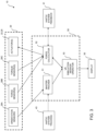
- FIG. 3 is a block diagram of a virtual surgery processor unit for operating the impactor mechanism of FIG. 1 , in virtual reality surgery simulation;
- FIG. 4 is a block diagram of a virtual surgery processor unit for operating the impactor mechanism of FIG. 1 , in telesurgery;
- FIG. 5 is a perspective view of an embodiment of the impactor mechanism of FIG. 1 ;
- FIG. 6 is a sectional view of the impactor mechanism of FIG. 5 .
- the virtual surgery system 10 may be a virtual reality (VR) surgery simulation system, in which a VR surgery simulation session is performed. Accordingly, the system 10 may have an impactor mechanism 20 , a display unit 30 , a haptic system 40 , and a virtual surgery processor unit 50 :
- VR virtual reality
- the impactor mechanism 20 may have a base 21 .
- the base 21 may be a standalone base or may be integrated to a support table. As the base 21 may receive impacts with a lateral vector(s) during impacting, it is preferably made of a sturdy material to withstand impact forces.
- the base 21 may also be anchored to a support table or platform to stand still while receiving the impacts.
- the base 21 may also be referred to as a housing, casing, block, etc.
- FIG. 5 an exemplary embodiment of the impactor mechanism 20 is shown, with the base 21 including a casing 21 A with cover 21 B.
- the casing 21 A is of the type that may be anchored to a structure, such as a support table of the system 10 .
- the cover 21 B may be releasably connected to a remainder of the casing 21 A, for providing an access to an inner cavity of the casing 21 A.
- Other embodiment include access from a bottom (e.g., an inverted open box, etc).
- the cover 21 B may have an opening, such as a central opening, for an impactor shaft to project out of the casing 21 A.
- the base 21 in the embodiment of FIGS. 5 and 6 may also have a block 21 C, that may include various mechanical parts of the impactor mechanism 20 , as detailed hereinafter. Because of some play, the block 21 C may move relative to the casing 21 A. In an embodiment, the block 21 C may move in two or more translational degrees of freedom, such as in a planar movement relative to a plane of a support table.
- the block 21 C may be floating, and held in place by shock absorbing components.
- Shock absorbing components may be provided between the casing 21 A and the block 21 C, for instance in opposition to movement in the two horizontal translations.
- the shock absorbing components may be coil springs 21 D, though other components may be used, such as dampers, rubber pads, cylinders, dashpots, etc.
- the mechanical parts are connected directly to walls of the casing 21 A.
- the block 21 C is connected directly to the support table or structure, without casing 21 A, for instance as interfaced by vertical coil springs 21 D or like shock absorbing components.
- the shock absorption components could be in a shaft or joint of the impactor mechanism 10 .
- the base 21 houses a rotational joint 22 providing at least two rotational degrees of freedom (DOF), such as a ball forming a ball joint with the base 21 , or like rotational joint.
- Appropriate sensors are integrated into the base 21 in order to track movements of the ball 22 as a result of manipulations of a master impactor.
- the sensors may be optical sensors, rotary encoders, LEDs with imaging array of photodiodes, inertial sensors, among numerous possibilities, to track two or three DOFs of the ball 22 relative to the base 21 .
- an embodiment of the rotational joint features a rod end bearing 22 (a.k.a., heim joint, rose joint) including a ball swivel 22 A in a circular casing 22 B.
- the rod end bearing 22 may also have or may interact with a rod 22 C secured or rotatably mounted to the block 21 C.
- the rod 22 C is part of the block 21 C.
- a bearing 22 D may be in the ball swivel 22 A to rotatably interface the ball swivel 22 A to the rod 22 C.
- the bearing 22 D may be a low friction sleeve (e.g., PTFE, ceramic), a rolling element bearing (e.g., roller bearing).
- the bearing 22 may also include a shaft portion 22 E.
- the shaft portion 22 E may be a threaded shaft portion that is connected to the impactor shaft 23 .
- the shaft portion 22 E is the impactor shaft.
- joints that may be used include a universal joint, or interconnected rotational joints.
- the use of a ball joint is well suited for impaction, considering that the position of the center of rotation of the ball 22 is fixed in the base 21 .
- the base 21 may have an hemispherical interface surface in contact with the ball 22 on a substantial portion of the spherical surface of the ball 22 , whereby the connection is robust and suited to withstand impacts.
- Some rotational constraints may be applied to the rotational joint to mimic rotational resistance of an acetabular cup relative to the acetabulum in the virtual session or in the telesurgery session.
- the joint 22 may include translational joints providing one or two DOFs of translation, for example in a plane more or less parallel to that of the table. This may for example be achieved by the constrained movement enabled by the shock absorbing components, such as the coil springs 21 D, rubber blocks, etc.
- the resulting movement(s) may emulate the movement of a tool removing osteoma or osteophytes by impaction (e.g., such as a chisel).
- the master impactor may have different configurations, including one with an impactor shaft 23 and an impactor handle 24 , as in FIG. 1 .
- the impactor shaft 23 is shown as being straight, with a first end connected to the ball 22 , and a second end operationally connected to the handle 24 .
- the shaft 23 may be connected in any appropriate way to the ball 22 , including an integral monoblock fabrication, a screwing engagement, etc.
- the impactor shaft 23 is threadingly engaged to the threaded shaft portion 22 E of the rod end bearing 22 .
- the shaft 23 is also shown as being substantially straight, but other shapes are considered as well.
- the shaft 23 may have an offset to emulate an offset impactor.
- the shafts may be interchanged to enable different shapes and sizes of shaft 23 to be used, to enable the use of different master impactor shapes and sizes in training or telesurgery sessions.
- the handle 24 may or may not be present, as a user may simply hold the shaft 23 .
- the handle 24 is sized to be representative of existing handle sizes and grips, to procure a real feel to the master impactor.
- the handle 24 is mounted to the shaft 23 by way of a translation joint 25 used to simulate the translation occurring during impaction, as the acetabular cup is forced into the acetabulum.
- the translation joint 25 may be actuated as a function of the impact force and calculated or measured resistance from the acetabular cup entering the acetabulum, in the virtual session or in the telesurgery session, respectively.
- the translation joint 25 between the shaft 23 and the handle 24 may be a linear actuator or pneumatic/hydraulic cylinder actuated proportionally to calculated or measured resistance and impact force to provide force feedback to the user.
- Other shock absorption means may be provided on the master impactor.
- the translation joint 25 may also include a passive shock absorber, such as a spring, pneumatic, and/or hydraulic damper, or combinations thereof.
- there is no translation joint 25 and consequently, no force feedback on the impaction.
- the shaft 23 is tubular, and has an end of the translation joint 25 projecting out of the impact end of the shaft 23 . Accordingly, it is the end of the translation joint 25 that receives the impacts.
- the translation joint 25 has hollow-lock set screws 25 A threadingly engaged in the inner cavity of the shaft 23 , the inner cavity having corresponding threading.
- the hollow-lock set screws 25 A may also be known as supports, sliders, jam set screws, or simply set screws, etc.
- the central bore 25 B may have any appropriate shape (circular, square, etc), but in an embodiment the central bore 25 B is non circular.
- the central bore 25 B is hexagonal. This may facilitate the engagement of the hollow-lock set screws 25 A in the shaft 23 , for example by the use of an Allen key.
- the central bore(s) 25 B may also be concentrically positioned in the shaft 23 .
- the translation joint 25 may further include rod 25 C.
- the rod 25 C may have different configurations, including the one illustrated of a threaded rod portion 25 C 1 with sleeves 25 C 2 thereon.
- the sleeves 25 C 2 have a shape complementary to that of the central bores 25 B, such as hexagonal. Therefore, as seen in the arrangement of FIG. 6 , the sleeves 25 C 2 are in sliding engagement in the central bores 25 B. If the central bores 25 B are non-circular, the movement of the rod 25 C will be substantially translational (i.e., one degree of freedom of translation). As an alternative to the non-circularity, other mechanisms may be used to constrain the movements to a translation.
- rod 25 C may also be received directly in the shaft 23 , in sliding engagement, i.e., without the hollow-lock set screws 25 A.
- a head 26 may be located at the end of the handle 24 , and thus act as impactor head.
- the head 26 is screwingly engaged to the threaded rod portion 25 C 1 , though it may also be a monoblock part of the rod 25 C in an alternative embodiment.
- the head 26 may include any appropriate sensors to measure the forces applied to the master impactor during impaction.
- the sensors in the head 26 may include a force sensor measuring the axial force resulting from the hammering on the master impactor.
- the force sensor may be supplemented by torque sensors to measure bending of the master impactor, as bending may be symptomatic of lateral forces/side loads during impaction.
- the bending loads are measured about two axes, transverse to the longitudinal axis of the master cylinder.
- the force and torque sensors may be located at any appropriate locations on the master impactor, such as at any point along the axis of the shaft 23 or handle 24 , or in the spherical joint.
- the force and torque sensors are located in a portion of the shaft 23 adjacent to the ball 22 . This lower portion of the shaft 23 may be separable from a remainder of the shaft 23 and handle 24 , as shown at joint 27 (for instance the joint 27 is the threaded engagement between the threaded shaft portion 22 E of the rod end bearing 22 and the shaft 23 ).
- the orientation of the master impactor is measured by way of the sensors in the spherical joint, as described previously, for example in two rotational degrees of freedom. It may not be necessary to determine an orientation of the master impactor about its longitudinal axis as such a rotation does not affect the orientation of the acetabular cup.
- the various sensors of the impactor mechanism 20 are shown as orientation sensors 28 A, force sensor(s) 28 B and torque sensor(s) 28 C in FIGS. 3 and 4 .
- the orientation sensors 28 A are those determining the orientation of the master impactor, for its real-time tracking.
- the orientation sensors 28 A may be any type of sensor, such as inertial sensors (accelerometers, gyroscope, inclinometers), optical encoders, etc.
- the force sensor(s) 28 B are used to measure the impact force.
- the force sensors 28 B may be strain gauges, etc.
- the torque sensor(s) 28 C measure bending of the master impactor.
- the torque sensors 28 C may be strain gauges, etc.
- the force sensors 28 B and/or the torque sensors 28 C may include one or more strain gauge load cells, piezoelectric load cells, hydraulic load cells, pneumatic load cells, vibrating string load cells, capacitive load cells, among other possibilities.
- a hammer or like impacting tool is shown at 29 in FIG. 1 . Referring to FIGS. 5 and 6 , the force sensor 28 B is shown inside the shaft 23 , in communication with the translation joint 25 , to quantify the impacts received on the sensor head 26 .
- the measured force is representative in magnitude to forces that would be transmitted to an impactor.
- the shock absorption components e.g., coil springs 21 D
- the force transmitted to the base 21 and support table is spread over time, which decreases the amplitude of its peak value, but extends its effect in time. It also have a reflective effect, returning some of the transmitted energy to the user's hand holding the shaft, for feedback. This may have a protective effect on surrounding equipment.
- the orientation sensors 28 A are for example accelerometers surrounding the shaft 23 , at or near the junction with the rod end bearing 22 .
- the orientation sensors 28 A may be located elsewhere along the shaft 23 , for instance closer to the joint end than to the impact end.
- the system 10 has a display unit 30 , shown as being a vertical monitor.
- the system 10 may have more than one display unit 30 , including a horizontal monitor 30 A in FIG. 2 , to enable a user of the system 10 to overlook an anatomical location 31 displayed by the system 10 during a virtual surgery session, and hence reproduce the point of view of an operator in surgery.
- a secondary vertical monitor 30 B may be provided for other personnel to view actions resulting from the interaction between the main user and the system 10 via the primary monitor 30 A.
- the anatomical location 31 is shown in the context of hip arthroplasty, or acetabular cup implanting.
- the anatomical location 31 includes an acetabular cup 32 , an impactor 33 , and retractors 34 .
- the display may be a graphic user interface and/or computer generated graphics including simulation models, in the case of VR simulation, or may be live camera footage in telesurgery, in which the anatomical location 31 and instruments 32 , 33 and 34 are real. It bears mentioning that other instruments and bones may be displayed in hip surgery, including cup reamers, drills, etc, and those may be displayed as well, prior to or after impaction.
- the display of the display unit 30 also has a frame of reference shown as X, Y, Z in FIG. 1 .
- the frame of reference may also be known as coordinate system, a referential system, etc.
- the orientation of the master impactor of the impactor mechanism 20 is calibrated to match the orientation of the impactor 33 in the frame of reference on the display unit 30 , at least during impaction steps.
- any generic tool supported by the haptic system 40 is tracked during virtual sessions in the frame of reference of the display, for the concurrent movement of slave instruments in the virtual session.
- Other information may be displayed on the monitor 30 B, such as pre-operative or intraoperative medical images (e.g., X-rays, scans, MRI models, etc), navigational data.
- the monitor 30 B may be a tablet like monitor enabling touch interfaces by the user of the system 10 .
- the haptic system 40 is shown as having any appropriate force-feedback manipulator 41 supporting one or more mock-up surgical tools 42 .
- the mock-up surgical tools may be interchanged during a procedure as a function of a surgical flow.
- the force-feedback manipulator 41 is shown as having a parallel configuration, although a serial arm could be used as well.
- the haptic system 40 includes a tracking apparatus 43 , to determine the position and orientation of the surgical tools 42 , and hence control the slave tools 33 and 34 as a function of the tracking in the frame of reference of the system 10 .
- the tracking apparatus 43 may employ any appropriate technology, such as joint sensors (rotary encoders, optical sensors, etc), inertial sensors, optical tracking, etc.
- the tracking apparatus is globally shown as 43 , but it is to be understood that the tracking apparatus 43 may include numerous components in the force-feedback manipulator 41 . Likewise, some of the actuators of the force-feedback manipulator 41 may be located in the casing labelled tracking apparatus 43 .
- the force-feedback manipulator 41 has haptic capacity, for instance by actuators and a transmission (e.g., gears, tendons, etc) for a user to receive force feedback as a function of forces occurring at the slave side of the system 10 .
- the impactor mechanism 20 is shown being separated from the haptic system 40 .
- the system 10 provides robust hardware for the higher force, lower accuracy maneuvers, and precise instrument for the higher DOF, lower force maneuvers. Therefore, the haptic system 40 is not hampered by a force-feedback manipulator 41 (a.k.a., haptic system feedback 41 ) capable of withstanding impacting forces at any orientation.
- the impactor mechanism 20 may be releasably coupled to the haptic system 40 during impaction simulation or impaction use.
- the force-feedback manipulator 41 may provide force feedback against rotation of the shaft 23 relative to the base 21 , while the base 21 absorbs the impacting forces.
- the various orientation sensors e.g., 28 A
- the impactor mechanism 20 is operated without force feedback.
- the virtual surgery processor unit 50 executing the VR surgery simulation session is shown in greater details.
- the virtual surgery processor unit 50 is any processor (laptop, computer, etc) having suitable processing speed in order to perform VR surgery simulation or telepresence surgery (a.k.a., telesurgery) in real-time, i.e., to produce real-time graphic rendering of manipulations of master devices in virtual sessions.
- the virtual surgery processor unit 50 may also optionally produce real-time force feedback to master devices during the virtual sessions.
- the virtual surgery system processor unit 50 may therefore have various modules that perform steps and functions as described hereinafter.
- the various steps and modules may be in the form of computer program products with a computer-readable memory storing computer executable instructions thereon that, when executed by a computer such as the virtual surgery processor unit 50 , perform the method steps and/or functions described herein.
- the virtual surgery processor unit 50 may have a master tracker module 51 , tasked with tracking an orientation of the master impactor (e.g., impactor 20 ) via signals provided by the orientation sensors 28 A. If the haptic system 40 is part of the system 10 , the master tracker module 51 may receive signals from the tracking apparatus 43 ( FIG. 2 ) as well, to track the position and/or orientation of mock-up instrumentation.
- the master tracker module 51 may be configured to filter out readings of the orientation sensors 28 A having occurred during impaction: such impacts may have an effect on the readings of given types of orientation sensors 28 A, such as accelerometers. By filtering out such values, the orientation readings may be more stable over time.
- One contemplated method to filter out is to correlate the impact forces with the orientation readings on a time scale, and remove orientation readings at instants of measured impacts.
- the virtual surgery processor unit 50 may have a force calculator module 52 that measures the forces (e.g., including torque) during impaction on the impactor mechanism 20 . The measuring is done using the signals received from the force sensor(s) 28 B and the torque sensor(s) 28 C.
- the force calculator module 52 may optionally drive the actuators present at the joints 22 and 25 if these joints are actuatable, based on calculated force feedback from the slave end of a virtual session.
- the force calculator module 52 may optionally drive the actuators present in the force-feedback manipulator 41 if the latter is used in conjunction with the impactor mechanism 20 as described above, again based on calculated force feedback from the slave end of a virtual session.
- the force calculator module 52 may receive signals from the force-feedback manipulator 42 ( FIG. 2 ), to measure force inputs on the mock-up instrumentation and drive the force-feedback manipulator 42 in providing force feedback to a user as a function of forces originating from actions in or at the slave end of the virtual session.
- the force calculator module 52 may also amplify, filter, over-sample, threshold, the raw data from the force sensors 28 B, to ensure the proper assessment of the forces. Such functions may be performed at the force sensors 28 B as well.
- a VR simulation session operator 53 runs the virtual simulation session.
- the VR simulation session operator 53 controls the session flow, i.e., the sequences of steps of the session in accordance with a simulated surgical procedure.
- the VR simulation session operator 53 may also receive tracking data from the master tracker module 51 and force data from the force calculator module 52 and consequently determine the position and orientation of corresponding slave objects in the VR simulation, in the frame of reference.
- the VR simulation session operator 53 may therefore determine interactions, such as contacts, alterations, between virtual slave objects at the virtual slave end of the simulation, in response to the tracking by the master tracker module 51 . Consequently, the VR simulation session operator 53 may output force feedback data for the force calculator module 52 to drive the actuator(s) 22 and 25 if present, though the force feedback may be optional.
- the VR simulation session operator 53 may generate graphics depicting a virtual slave end, as shown at 31 in FIG. 1 , for display on the display unit 30 .
- the graphics are updated in real-time by the virtual surgery processor unit 50 as a function of manipulations of the master instrumentation.
- the VR simulation session operator 53 may include a cup orientation calculator module.
- the cup orientation calculator module may calculate current cup implant orientation from a tracking of the orientation of the master impactor by the master tracker module 51 .
- the cup orientation calculator module may express the current cup implant orientation in the VR simulation, i.e., the orientation of the slave impactor relative to the pelvis in angles in the frontal, sagittal, and/or transverse planes.
- the cup orientation calculator module may also or alternatively express the current cup implant orientation as abduction and inclination values. This may help the user of the system 10 to properly orient the master impactor of the impactor mechanism 20 .
- the VR simulation session operator 53 may include an impacting assessor module to assess if the right force and right angle are input on the impactor mechanism 20 to achieve the desired cup implant orientation.
- the impacting assessor module receives tracking data from the master tracking module 51 , the force data from the force calculator module 52 , as well as interactions between virtual objects, such as between virtual cup 32 and virtual acetabulum.
- the interactions may be in the form of virtual models with virtual frictional forces and size data, according to which data the resistance to penetration of the virtual cup 32 in the virtual acetabulum may be determined.
- the impacting assessor module determines any variation of orientation of the cup from the desired cup implant orientation, as a result of non-axial impacting/hand movement on the impactor mechanism 20 .
- the impacting assessor module may also provide corrective values or qualitative information to explain any form of variation in the impacting.
- the corrective values may be in a real-time update of inclination and abduction values, for example, as well as a variation value, such as a percentage, relative to the desired cup implant orientation.
- the qualitative information may be in the form of observations: holding-hand shift during impacting, impact with non-negligible side load (e.g., right, left, up, down), excessive force, or excess impacts. All information is consequently displayed on the display unit 30 .
- the system 10 may have the capacity of emitting sounds indicative of actions and warnings, for example. The sound emission may be part of the feedback provided to the user.
- FIG. 3 refers to the VR surgery simulation.
- the impactor mechanism 20 may also be employed in remote virtual surgery for instance with a robotic slave system 60 performing real surgery remotely.
- the robotic slave system 60 may consequently include a processor unit similar to the one shown at 50 .
- the system 10 is similar whether it runs a VR surgery simulation as in FIG. 3 , or a telesurgery procedure as in FIG. 4 , whereby like numerals will refer to like components.
- the virtual surgery processor unit 50 has a telesurgery session operator 54 running the telesurgery surgery session.
- the telesurgery session operator 54 controls the session flow, i.e., the sequences of steps of the session in accordance with a surgical procedure, and as a response of bilateral communication with the robotic slave system 60 .
- the telesurgery session operator 54 may also receive tracking data from the master tracker module 51 and force data from the force calculator module 52 and consequently drive or send information to the robotic slave system 60 .
- the telesurgery session operator 54 may receive force feedback and positional data for the slave objects at the robotic slave system 60 .
- the telesurgery session operator 54 may output force feedback data for the force calculator module 52 to drive the actuator(s) 22 and 25 if present, or the force-feedback manipulator 41 if used, though the force feedback is optional with the impactor mechanism 20 .
- the telesurgery session operator 54 may treat video footage taken by the robotic slave system 60 , with additional navigational data added, such as virtual axes and values, for display on the display unit 30 (e.g., augmented reality).
- the navigational data may be updated in real-time by the virtual surgery processor unit 50 as a function of manipulations of the master instrumentation.
- the telesurgery session operator 54 may also include the cup orientation calculator module, operating in a similar fashion as for the VR simulation session operator 53 ( FIG. 3 ).
- the cup orientation calculator module may calculate current cup implant orientation from a tracking of the orientation of the master impactor by the master tracker module 51 .
- the cup orientation calculator module may express the current cup implant orientation, i.e., the orientation of the slave impactor relative to the pelvis in angles in the frontal, sagittal, and/or transverse planes at the robotic slave system 60 .
- the cup orientation calculator module may also or alternatively express the current cup implant orientation as abduction and inclination values. This may help the user of the system 10 to properly orient the master impactor of the impactor mechanism 20 .
- the impacting may be performed by the user, and cause impaction at the robotic slave system 60 , although the robotic slave system 60 may impact the cup at the slave end based on the desired cup implant orientation.
- the telesurgery session operator 54 may include an impacting assessor module to assess if the right force and right angle are input on the impactor mechanism 20 to achieve the desired cup implant orientation.
- the impacting assessor module receives tracking data from the master tracking module 51 , the force data from the force calculator module 52 , as well as interactions between bone and instruments at the slave end.
- the impacting assessor module determines any variation of orientation of the cup from the desired cup implant orientation, as a result of non-axial impacting/hand movement on the impactor mechanism 20 .
- the impacting assessor module may also provide corrective values to explain any form of variation in the impacting.
- the corrective values may be in a real-time update of inclination and abduction values, for example, as well as a variation value, such as a percentage, relative to the desired cup implant orientation. All information is consequently displayed on the display unit 30 .
- the present disclosure has been focusing on acetabular cup placement, it is contemplated to use the impactor mechanism 20 for other procedures in which impacting is required.
- the system 10 with the impactor mechanism 20 may be used to simulate or perform in telesurgery the removal of osteoma and osteophytes with chisel-like tools, the impaction of an intramedullary nail or rod in a medullary canal of a long bone, the positioning of a cut or drill guide in knee arthroplasty, bone graft impaction, intervertebral implant insertion, impaction of femoral knee prosthesis, shoulder prosthesis, elbow prosthesis.
- the impactor mechanism 20 is self-standing, self-support, and/or independent from a haptic system. By having the base 21 at the impact end, a substantial portion of the impacts transmitted to the base 21 are spread to a structure of the system 10 , as opposed to being transmitted to a mechanism such as a haptic or robotic arm.
Landscapes
- Health & Medical Sciences (AREA)
- Engineering & Computer Science (AREA)
- Life Sciences & Earth Sciences (AREA)
- Surgery (AREA)
- General Health & Medical Sciences (AREA)
- Nuclear Medicine, Radiotherapy & Molecular Imaging (AREA)
- Heart & Thoracic Surgery (AREA)
- Veterinary Medicine (AREA)
- Animal Behavior & Ethology (AREA)
- Public Health (AREA)
- Biomedical Technology (AREA)
- Medical Informatics (AREA)
- Molecular Biology (AREA)
- Theoretical Computer Science (AREA)
- Business, Economics & Management (AREA)
- General Physics & Mathematics (AREA)
- Physics & Mathematics (AREA)
- Orthopedic Medicine & Surgery (AREA)
- Educational Technology (AREA)
- Educational Administration (AREA)
- Robotics (AREA)
- Transplantation (AREA)
- Oral & Maxillofacial Surgery (AREA)
- Radiology & Medical Imaging (AREA)
- Gynecology & Obstetrics (AREA)
- Vascular Medicine (AREA)
- Cardiology (AREA)
- Physical Education & Sports Medicine (AREA)
- Pathology (AREA)
- Algebra (AREA)
- Mathematical Physics (AREA)
- Pure & Applied Mathematics (AREA)
- Mathematical Optimization (AREA)
- Mathematical Analysis (AREA)
- Computational Mathematics (AREA)
- Entrepreneurship & Innovation (AREA)
- Medicinal Chemistry (AREA)
- Chemical & Material Sciences (AREA)
- Pulmonology (AREA)
- Prostheses (AREA)
Abstract
Description
-
- The
impactor mechanism 20 is the master device (master impactor) manipulated by a user of thesystem 10 to control the slave impactor device in the simulation session, or in a telesurgery session (also a form a virtual surgery). - The
display unit 30 outputs the graphic display of the simulation session. As detailed hereinafter, thedisplay unit 30 may be a monitor with 2D or 3D display, a tablet, etc. Thedisplay unit 30 may be also be a VR headset, among possibilities. Thedisplay unit 30 in its various forms may also provide an augmented reality (AR) output, for instance in the case of telesurgery. - A
haptic system 40 is another master device manipulated by the user of thesystem 10 to control corresponding slave devices in the simulation session, or in a telesurgery session, in preparation for or in conclusion to impaction with theimpactor mechanism 20. - The virtual
surgery processor unit 50 executes the VR surgery simulation session in the exemplary embodiment, or in a telesurgery session. - A
robotic slave system 60 may also be part of thesystem 10, in the context of a telesurgery use of theimpactor mechanism 20.
- The
Claims (20)
Priority Applications (1)
| Application Number | Priority Date | Filing Date | Title |
|---|---|---|---|
| US16/765,732 US11631341B2 (en) | 2017-11-21 | 2018-11-16 | Impactor mechanism for virtual reality surgery simulation system and telesurgery |
Applications Claiming Priority (3)
| Application Number | Priority Date | Filing Date | Title |
|---|---|---|---|
| US201762589286P | 2017-11-21 | 2017-11-21 | |
| PCT/CA2018/051458 WO2019100148A1 (en) | 2017-11-21 | 2018-11-16 | Impactor mechanism for virtual reality surgery simulation system and telesurgery |
| US16/765,732 US11631341B2 (en) | 2017-11-21 | 2018-11-16 | Impactor mechanism for virtual reality surgery simulation system and telesurgery |
Publications (2)
| Publication Number | Publication Date |
|---|---|
| US20200294423A1 US20200294423A1 (en) | 2020-09-17 |
| US11631341B2 true US11631341B2 (en) | 2023-04-18 |
Family
ID=66630366
Family Applications (1)
| Application Number | Title | Priority Date | Filing Date |
|---|---|---|---|
| US16/765,732 Active 2039-11-23 US11631341B2 (en) | 2017-11-21 | 2018-11-16 | Impactor mechanism for virtual reality surgery simulation system and telesurgery |
Country Status (4)
| Country | Link |
|---|---|
| US (1) | US11631341B2 (en) |
| EP (1) | EP3714448B1 (en) |
| CA (1) | CA3120656A1 (en) |
| WO (1) | WO2019100148A1 (en) |
Families Citing this family (20)
| Publication number | Priority date | Publication date | Assignee | Title |
|---|---|---|---|---|
| US11957635B2 (en) | 2015-06-20 | 2024-04-16 | Therabody, Inc. | Percussive therapy device with variable amplitude |
| FR3071719B1 (en) * | 2017-09-29 | 2022-06-03 | Centre Nat Rech Scient | DEVICE FOR INSERTING A SURGICAL IMPLANT |
| FR3071718B1 (en) * | 2017-09-29 | 2021-11-05 | Centre Nat Rech Scient | SURGICAL IMPLANT INSERTION DEVICE |
| GB201800701D0 (en) * | 2018-01-16 | 2018-02-28 | Depuy Ireland Ultd Co | Surgical Impaction apparatus and method |
| US11452670B2 (en) * | 2018-12-26 | 2022-09-27 | Therabody, Inc. | Percussive therapy device with orientation, position, and force sensing and accessory therefor |
| US10940081B2 (en) | 2019-05-07 | 2021-03-09 | Theragun, Inc. | Percussive massage device with force meter |
| US12064387B2 (en) | 2018-12-26 | 2024-08-20 | Therabody, Inc. | Percussive therapy device with electrically connected attachment |
| US11890253B2 (en) | 2018-12-26 | 2024-02-06 | Therabody, Inc. | Percussive therapy device with interchangeable modules |
| US11813221B2 (en) | 2019-05-07 | 2023-11-14 | Therabody, Inc. | Portable percussive massage device |
| US11998504B2 (en) | 2019-05-07 | 2024-06-04 | Therabody, Inc. | Chair including percussive massage therapy |
| US20210298795A1 (en) * | 2020-03-27 | 2021-09-30 | Mako Surgical Corp. | Robotic Spine Surgery System And Methods With Haptic Interface |
| EP4272682A4 (en) * | 2021-02-01 | 2024-06-05 | Wuhan United Imaging Healthcare Surgical Technology Co., Ltd. | Master manipulator manipulation device for robot |
| US12193718B2 (en) | 2021-04-09 | 2025-01-14 | Smith & Nephew, Inc. | Orthopedic surgical instrument |
| US11857481B2 (en) | 2022-02-28 | 2024-01-02 | Therabody, Inc. | System for electrical connection of massage attachment to percussive therapy device |
| CN116687630B (en) * | 2022-12-30 | 2024-06-25 | 北京和华瑞博医疗科技有限公司 | Prosthesis installation actuator and surgical system |
| DE102022128868A1 (en) | 2022-11-01 | 2024-05-02 | Technische Universität Chemnitz, Körperschaft des öffentlichen Rechts | Impact device for haptic simulation of hammering work steps |
| US12295900B1 (en) | 2022-12-21 | 2025-05-13 | Therabody, Inc. | Systems, methods, and devices for percussive massage therapy with voice activation |
| US12402686B2 (en) | 2023-06-14 | 2025-09-02 | Therabody, Inc. | Articles of footwear having therapeutic assemblies |
| WO2025059992A1 (en) | 2023-09-21 | 2025-03-27 | Therabody, Inc. | Systems, methods, and devices for percussive massage therapy |
| US20250387239A1 (en) * | 2024-06-25 | 2025-12-25 | Orthoiq, Llc | Force sensing devices and methods for orthopedic surgery |
Citations (11)
| Publication number | Priority date | Publication date | Assignee | Title |
|---|---|---|---|---|
| US7001393B2 (en) | 2003-11-10 | 2006-02-21 | Rush University Medical Center | Servo-controlled impacting device for orthopedic implants |
| CN102208150A (en) * | 2011-05-13 | 2011-10-05 | 武汉理工大学 | Six-degree-of-freedom force-feedback virtual surgical instrument |
| CA2823207A1 (en) | 2010-12-29 | 2012-07-05 | Christopher Pedicini | Electric motor driven tool for orthopedic impacting |
| EP2476397A1 (en) | 2011-01-17 | 2012-07-18 | Greatbatch Medical SA | Straight cup impactor with lever arm |
| US8236005B2 (en) | 2006-11-28 | 2012-08-07 | Robert Michael Meneghini | System and method for preventing intraoperative fracture in cementless hip arthroplasty |
| CA2872182A1 (en) | 2012-05-08 | 2013-11-14 | Medical Enterprises, Llc | Electric motor driven tool for orthopedic impacting |
| CA2872180A1 (en) | 2012-05-08 | 2013-11-14 | Medical Enterprises, Llc | Electric motor driven tool for orthopedic impacting |
| EP2923677A1 (en) | 2014-03-27 | 2015-09-30 | Centre National De La Recherche Scientifique (Cnrs) | Device for assisting with the placement of an orthopaedic instrument |
| US20150282856A1 (en) | 2014-04-02 | 2015-10-08 | Centre National De La Recherche Scientifique (Cnrs) | Device for assisting with the placement of an orthopedic instrument |
| CN105291138A (en) * | 2015-11-26 | 2016-02-03 | 华南理工大学 | Visual feedback platform improving virtual reality immersion degree |
| EP3111897A1 (en) | 2015-07-02 | 2017-01-04 | Greatbatch Ltd. | Hybrid straight cup impactor |
-
2018
- 2018-11-16 CA CA3120656A patent/CA3120656A1/en active Pending
- 2018-11-16 EP EP18880784.6A patent/EP3714448B1/en active Active
- 2018-11-16 WO PCT/CA2018/051458 patent/WO2019100148A1/en not_active Ceased
- 2018-11-16 US US16/765,732 patent/US11631341B2/en active Active
Patent Citations (14)
| Publication number | Priority date | Publication date | Assignee | Title |
|---|---|---|---|---|
| US7001393B2 (en) | 2003-11-10 | 2006-02-21 | Rush University Medical Center | Servo-controlled impacting device for orthopedic implants |
| US8236005B2 (en) | 2006-11-28 | 2012-08-07 | Robert Michael Meneghini | System and method for preventing intraoperative fracture in cementless hip arthroplasty |
| CA2823207A1 (en) | 2010-12-29 | 2012-07-05 | Christopher Pedicini | Electric motor driven tool for orthopedic impacting |
| EP2476397A1 (en) | 2011-01-17 | 2012-07-18 | Greatbatch Medical SA | Straight cup impactor with lever arm |
| CN102208150A (en) * | 2011-05-13 | 2011-10-05 | 武汉理工大学 | Six-degree-of-freedom force-feedback virtual surgical instrument |
| CN102208150B (en) * | 2011-05-13 | 2013-03-20 | 武汉理工大学 | Six-degree-of-freedom force-feedback virtual surgical instrument |
| CA2872182A1 (en) | 2012-05-08 | 2013-11-14 | Medical Enterprises, Llc | Electric motor driven tool for orthopedic impacting |
| CA2872180A1 (en) | 2012-05-08 | 2013-11-14 | Medical Enterprises, Llc | Electric motor driven tool for orthopedic impacting |
| EP2923677A1 (en) | 2014-03-27 | 2015-09-30 | Centre National De La Recherche Scientifique (Cnrs) | Device for assisting with the placement of an orthopaedic instrument |
| FR3019031A1 (en) | 2014-03-27 | 2015-10-02 | Centre Nat Rech Scient | DEVICE FOR ASSISTING THE PLACEMENT OF AN ORTHOPEDIC INSTRUMENT |
| US20150282856A1 (en) | 2014-04-02 | 2015-10-08 | Centre National De La Recherche Scientifique (Cnrs) | Device for assisting with the placement of an orthopedic instrument |
| EP3111897A1 (en) | 2015-07-02 | 2017-01-04 | Greatbatch Ltd. | Hybrid straight cup impactor |
| CN105291138A (en) * | 2015-11-26 | 2016-02-03 | 华南理工大学 | Visual feedback platform improving virtual reality immersion degree |
| CN105291138B (en) * | 2015-11-26 | 2017-10-20 | 华南理工大学 | It is a kind of to strengthen the visual feedback platform of virtual reality immersion sense |
Also Published As
| Publication number | Publication date |
|---|---|
| WO2019100148A1 (en) | 2019-05-31 |
| US20200294423A1 (en) | 2020-09-17 |
| EP3714448A4 (en) | 2021-06-02 |
| EP3714448A1 (en) | 2020-09-30 |
| EP3714448B1 (en) | 2023-12-20 |
| CA3120656A1 (en) | 2019-05-31 |
Similar Documents
| Publication | Publication Date | Title |
|---|---|---|
| US11631341B2 (en) | Impactor mechanism for virtual reality surgery simulation system and telesurgery | |
| US11517382B2 (en) | Method and device for cup implanting using inertial sensors | |
| US11833063B2 (en) | Soft tissue balancing in robotic knee surgery | |
| US20110306873A1 (en) | System for performing highly accurate surgery | |
| Tendick et al. | Sensing and manipulation problems in endoscopic surgery: experiment, analysis, and observation | |
| US9092996B2 (en) | Microsurgery simulator | |
| EP1737375B1 (en) | Computer-aided navigation systems for shoulder arthroplasty | |
| US10624711B2 (en) | Device for measuring femur displacement and method of making orthopedic measurements during a surgical procedure to correct a damaged hip | |
| EP4122415A1 (en) | Robotic revision knee arthroplasty virtual reconstruction system | |
| US12274631B2 (en) | Soft tissue balancing in robotic knee surgery | |
| Arant et al. | Alternative robotic control methods that account for system compliance decrease the errors in ligament tensions computed using the superposition method | |
| Matsunaga et al. | Multi functional drill incorporating linear motor for haptic surgical instrument and simulator | |
| Bjelland et al. | Implementation And Evaluation Of An Arthroscopic Tracker System For Intraoperative Motion Tracking And Force Registration. | |
| Waldron et al. | Mechanical characterization of the immersion corp. haptic, bimanual, surgical simulator interface | |
| Faieghi et al. | Vibration analysis in robot-driven glenoid reaming procedure | |
| US12042229B2 (en) | Patient-specific orthopedic implants and procedures using bone density | |
| Axford | Development of a Force-Based Ream Vector Measurement System For Glenoid Reaming Simulation | |
| RU181001U1 (en) | Device for simulating cavitary surgical interventions with tactile feedback | |
| Danieli et al. | Navi-Robot, a Navigator able to turn itself into a Robot to reach the correct position for a giventask during Orthopaedic Surgical Procedures. | |
| Maletsky | Validation of the next generation knee simulator | |
| Ting et al. | Development of a virtual reality surgical platform for unicompartmental knee replacement | |
| Danieli et al. | Actual developments of Navi-Robot, a navigator able to block itself in the correct position during orthopaedic surgical procedures | |
| Wulms | Design of a Force Measurement Table, providing objective force feedback during arthroscopic training on cadaver specimen | |
| Giles | Development of an In-Vitro Passive and Active Motion Simulator for the Investigation of Shoulder Function and Kinematics |
Legal Events
| Date | Code | Title | Description |
|---|---|---|---|
| FEPP | Fee payment procedure |
Free format text: ENTITY STATUS SET TO UNDISCOUNTED (ORIGINAL EVENT CODE: BIG.); ENTITY STATUS OF PATENT OWNER: SMALL ENTITY |
|
| FEPP | Fee payment procedure |
Free format text: ENTITY STATUS SET TO SMALL (ORIGINAL EVENT CODE: SMAL); ENTITY STATUS OF PATENT OWNER: SMALL ENTITY |
|
| STPP | Information on status: patent application and granting procedure in general |
Free format text: DOCKETED NEW CASE - READY FOR EXAMINATION |
|
| STPP | Information on status: patent application and granting procedure in general |
Free format text: NON FINAL ACTION MAILED |
|
| STPP | Information on status: patent application and granting procedure in general |
Free format text: RESPONSE TO NON-FINAL OFFICE ACTION ENTERED AND FORWARDED TO EXAMINER |
|
| STPP | Information on status: patent application and granting procedure in general |
Free format text: NOTICE OF ALLOWANCE MAILED -- APPLICATION RECEIVED IN OFFICE OF PUBLICATIONS |
|
| STCF | Information on status: patent grant |
Free format text: PATENTED CASE |
|
| AS | Assignment |
Owner name: LES TECHNOLOGIES OSSIM INC., CANADA Free format text: ASSIGNMENT OF ASSIGNORS INTEREST;ASSIGNOR:BLAIN, ANDRE;REEL/FRAME:063190/0765 Effective date: 20130221 Owner name: OSSIMTECH INC., CANADA Free format text: CHANGE OF NAME;ASSIGNOR:LES TECHNOLOGIES OSSIM INC.;REEL/FRAME:063228/0488 Effective date: 20160609 Owner name: OSSIMTECH INC., CANADA Free format text: ASSIGNMENT OF ASSIGNORS INTEREST;ASSIGNOR:HAY, ALEXANDER;REEL/FRAME:063187/0981 Effective date: 20180330 Owner name: OSSIMTECH INC., CANADA Free format text: ASSIGNMENT OF ASSIGNORS INTEREST;ASSIGNOR:JOMPHE, SEBASTIEN;REEL/FRAME:063187/0399 Effective date: 20180330 Owner name: LA FONDATION DE L'HOPITAL MAISONNEUVE-ROSEMONT, CANADA Free format text: ASSIGNMENT OF ASSIGNORS INTEREST;ASSIGNOR:MASSE, VINCENT;REEL/FRAME:063188/0591 Effective date: 20230227 Owner name: OSSIMTECH INC., CANADA Free format text: ASSIGNMENT OF ASSIGNORS INTEREST;ASSIGNOR:JOUAULT, ERWAN;REEL/FRAME:063187/0164 Effective date: 20180507 Owner name: OSSIMTECH INC., CANADA Free format text: ASSIGNMENT OF ASSIGNORS INTEREST;ASSIGNOR:DELORME, SEBASTIEN;REEL/FRAME:063186/0596 Effective date: 20191107 Owner name: OSSIMTECH INC., CANADA Free format text: ASSIGNMENT OF ASSIGNORS INTEREST;ASSIGNOR:LA FONDATION DE L'HOPITAL MAISONNEUVE-ROSEMONT;REEL/FRAME:063189/0663 Effective date: 20170901 |
|
| AS | Assignment |
Owner name: SIMGERY INC., CANADA Free format text: CHANGE OF NAME;ASSIGNOR:OSSIMTECH INC.;REEL/FRAME:063266/0840 Effective date: 20200304 Owner name: SYMGERY INC., CANADA Free format text: CHANGE OF NAME;ASSIGNOR:SIMGERY INC.;REEL/FRAME:063281/0235 Effective date: 20200409 |
|
| AS | Assignment |
Owner name: CEDAROME CANADA INC., CANADA Free format text: MERGER;ASSIGNOR:SYMGERY INC.;REEL/FRAME:064042/0057 Effective date: 20220201 |