US11623306B2 - Brazing filler material for bonding iron-based sintered member, and method for producing iron-based sintered part - Google Patents
Brazing filler material for bonding iron-based sintered member, and method for producing iron-based sintered part Download PDFInfo
- Publication number
- US11623306B2 US11623306B2 US17/283,818 US201917283818A US11623306B2 US 11623306 B2 US11623306 B2 US 11623306B2 US 201917283818 A US201917283818 A US 201917283818A US 11623306 B2 US11623306 B2 US 11623306B2
- Authority
- US
- United States
- Prior art keywords
- filler material
- brazing filler
- iron
- sintered compact
- sintered
- Prior art date
- Legal status (The legal status is an assumption and is not a legal conclusion. Google has not performed a legal analysis and makes no representation as to the accuracy of the status listed.)
- Active
Links
Images


Classifications
-
- B—PERFORMING OPERATIONS; TRANSPORTING
- B23—MACHINE TOOLS; METAL-WORKING NOT OTHERWISE PROVIDED FOR
- B23K—SOLDERING OR UNSOLDERING; WELDING; CLADDING OR PLATING BY SOLDERING OR WELDING; CUTTING BY APPLYING HEAT LOCALLY, e.g. FLAME CUTTING; WORKING BY LASER BEAM
- B23K35/00—Rods, electrodes, materials, or media, for use in soldering, welding, or cutting
- B23K35/22—Rods, electrodes, materials, or media, for use in soldering, welding, or cutting characterised by the composition or nature of the material
- B23K35/24—Selection of soldering or welding materials proper
- B23K35/30—Selection of soldering or welding materials proper with the principal constituent melting at less than 1550°C
- B23K35/3033—Ni as the principal constituent
-
- B—PERFORMING OPERATIONS; TRANSPORTING
- B22—CASTING; POWDER METALLURGY
- B22F—WORKING METALLIC POWDER; MANUFACTURE OF ARTICLES FROM METALLIC POWDER; MAKING METALLIC POWDER; APPARATUS OR DEVICES SPECIALLY ADAPTED FOR METALLIC POWDER
- B22F7/00—Manufacture of composite layers, workpieces, or articles, comprising metallic powder, by sintering the powder, with or without compacting wherein at least one part is obtained by sintering or compression
- B22F7/06—Manufacture of composite layers, workpieces, or articles, comprising metallic powder, by sintering the powder, with or without compacting wherein at least one part is obtained by sintering or compression of composite workpieces or articles from parts, e.g. to form tipped tools
- B22F7/062—Manufacture of composite layers, workpieces, or articles, comprising metallic powder, by sintering the powder, with or without compacting wherein at least one part is obtained by sintering or compression of composite workpieces or articles from parts, e.g. to form tipped tools involving the connection or repairing of preformed parts
-
- B—PERFORMING OPERATIONS; TRANSPORTING
- B23—MACHINE TOOLS; METAL-WORKING NOT OTHERWISE PROVIDED FOR
- B23K—SOLDERING OR UNSOLDERING; WELDING; CLADDING OR PLATING BY SOLDERING OR WELDING; CUTTING BY APPLYING HEAT LOCALLY, e.g. FLAME CUTTING; WORKING BY LASER BEAM
- B23K35/00—Rods, electrodes, materials, or media, for use in soldering, welding, or cutting
- B23K35/02—Rods, electrodes, materials, or media, for use in soldering, welding, or cutting characterised by mechanical features, e.g. shape
- B23K35/0222—Rods, electrodes, materials, or media, for use in soldering, welding, or cutting characterised by mechanical features, e.g. shape for use in soldering or brazing
- B23K35/0244—Powders, particles or spheres; Preforms made therefrom
-
- C—CHEMISTRY; METALLURGY
- C22—METALLURGY; FERROUS OR NON-FERROUS ALLOYS; TREATMENT OF ALLOYS OR NON-FERROUS METALS
- C22C—ALLOYS
- C22C1/00—Making non-ferrous alloys
- C22C1/04—Making non-ferrous alloys by powder metallurgy
- C22C1/0433—Nickel- or cobalt-based alloys
-
- C—CHEMISTRY; METALLURGY
- C22—METALLURGY; FERROUS OR NON-FERROUS ALLOYS; TREATMENT OF ALLOYS OR NON-FERROUS METALS
- C22C—ALLOYS
- C22C19/00—Alloys based on nickel or cobalt
- C22C19/03—Alloys based on nickel or cobalt based on nickel
-
- C—CHEMISTRY; METALLURGY
- C22—METALLURGY; FERROUS OR NON-FERROUS ALLOYS; TREATMENT OF ALLOYS OR NON-FERROUS METALS
- C22C—ALLOYS
- C22C30/00—Alloys containing less than 50% by weight of each constituent
- C22C30/02—Alloys containing less than 50% by weight of each constituent containing copper
-
- B—PERFORMING OPERATIONS; TRANSPORTING
- B22—CASTING; POWDER METALLURGY
- B22F—WORKING METALLIC POWDER; MANUFACTURE OF ARTICLES FROM METALLIC POWDER; MAKING METALLIC POWDER; APPARATUS OR DEVICES SPECIALLY ADAPTED FOR METALLIC POWDER
- B22F2301/00—Metallic composition of the powder or its coating
- B22F2301/15—Nickel or cobalt
-
- B—PERFORMING OPERATIONS; TRANSPORTING
- B22—CASTING; POWDER METALLURGY
- B22F—WORKING METALLIC POWDER; MANUFACTURE OF ARTICLES FROM METALLIC POWDER; MAKING METALLIC POWDER; APPARATUS OR DEVICES SPECIALLY ADAPTED FOR METALLIC POWDER
- B22F2301/00—Metallic composition of the powder or its coating
- B22F2301/35—Iron
-
- B—PERFORMING OPERATIONS; TRANSPORTING
- B22—CASTING; POWDER METALLURGY
- B22F—WORKING METALLIC POWDER; MANUFACTURE OF ARTICLES FROM METALLIC POWDER; MAKING METALLIC POWDER; APPARATUS OR DEVICES SPECIALLY ADAPTED FOR METALLIC POWDER
- B22F2998/00—Supplementary information concerning processes or compositions relating to powder metallurgy
- B22F2998/10—Processes characterised by the sequence of their steps
-
- C—CHEMISTRY; METALLURGY
- C22—METALLURGY; FERROUS OR NON-FERROUS ALLOYS; TREATMENT OF ALLOYS OR NON-FERROUS METALS
- C22C—ALLOYS
- C22C33/00—Making ferrous alloys
- C22C33/02—Making ferrous alloys by powder metallurgy
Definitions
- the present invention relates to a brazing filler material for bonding iron-based sintered member and a method for producing an iron-based sintered part.
- a powder metallurgy method in which a metal powder is compacted and the obtained green compact is sintered enables performing compacting into a near-net shape, and the method can be adopted to a method for producing various machine parts because the method is suitable for mass production.
- a green compact is usually prepared by using a green compact die formed of a die, an upper punch and a lower punch.
- a part with a shape of an undercut because a uniaxial compacting is performed from an upper direction and a lower direction. Therefore, when a part with the shape of the undercut is to be produced, the part is divided into a plurality of members, each having a shape in which compacting by uniaxial compacting is possible, the individual members of the shape are compacted, and then the plurality of members are combined and bonded.
- Examples of the method for bonding the plurality of members include the sintering diffusion bonding, brazing bonding and the like.
- brazing filler material used for bonding iron-based sintered members by brazing is Cu—Ni—Mn based alloy.
- the molten brazing filler material can react with Fe in the iron-based sintered members and can be solidified by the increase of a melting point by the reaction, and accordingly, further infiltration can be suppressed.
- the brazing filler material can reduce the amount of the brazing filler material to be absorbed in the pores and increase the amount of the brazing filler material that is remained at a bonding site, and thus, the brazing filler material can be preferably used for bonding the iron-based sintered members.
- a brazing method there is a method of applying the heat treatment by applying, to a brazing site of the member to be bonded, a paste-like brazing filler material in which particles of alloy powder are dispersed in the solvent.
- a paste-like brazing filler material in which particles of alloy powder are dispersed in the solvent.
- brazing method is a method in which the heat treatment is performed by arranging a brazing filler material which is a sintered compact formed by compacting alloy powder and applying the heat treatment at or near the brazing site of the member to be bonded.
- the brazing filler material has already been subjected to the heat treatment, and thus, the heat treatment in a brazing process can be performed more simply.
- the brazing filler material can be infiltrated in an interface of the member to be bonded, and accordingly, the bonding strength can be enhanced.
- Patent Document 1 (U.S. 2003/0062396 A1) discloses the production of a brazed compact for brazing metal components produced based on a powder metallurgy method by liquid phase sintering a filler metal having alloy powder containing Cu, Mn and Ni. Patent Document 1 discloses that the excessive infiltration of the brazing filler material into pores of the metal components can be prevented by compacting into the brazing filler material in advance.
- Patent Document 2 JP 2009-233720 A discloses that the limitation of the amount of oxygen in the brazing filler material for bonding iron-based sintered member containing Cu—Ni—Mn based alloy to account for not more than 0.1% by mass of a total amount, can prevent the occurrence of the bonding failure due to the oxidation and sulfidizing of Mn in Cu—Ni—Mn based alloy.
- Patent Document 2 by limiting the amount of oxygen in the brazing filler material, the bonding of oxygen and Mn in the brazing filler material can be prevented, and the variation in the Mn concentration in the brazing filler material can be prevented.
- the molten state of the brazing filler material can be caused to be uniform by suppressing the occurrence of MnO and making the Mn concentration uniform.
- Patent Document 2 JP 2009-233720 A
- impurity components may come into contact with the brazing filler material from a furnace atmosphere, a furnace material, a member to be bonded, and the like.
- an S component may be combined with the metal component in the brazing filler material to form metal sulfide.
- MnS may occur on a surface of the brazing filler material. The occurrence of MnS may decrease the amount of Mn in the brazing filler material and increase a melting point, and thus, MnS may act to inhibit the melting of the brazing filler material when the heat treatment is performed in the brazing process.
- Patent Document 1 discloses the brazing filler material using Cu—Ni—Mn based alloy, the possibility that the metal component contained in the brazing filler material is affected by oxidation or sulfidizing is not studied.
- Patent Document 2 discloses the brazing filler material using Cu—Ni—Mn based alloy, and the amount of oxygen in the brazing filler material is limited in order to prevent bonding of oxygen and Mn in the brazing filler material. On the other hand, even if the amount of oxygen in the brazing filler material is limited, a problem may be raised that the brazing filler material may be affected by the impurity components, especially the S component adhered from the outside during the heat treatment process.
- One of objects of the present invention is to improve the bondability by brazing iron-based sintered members.
- a brazing filler material for bonding iron-based sintered member having a sintered compact containing Cu, Mn, and a remainder of Ni and unavoidable impurities, and an oxide film formed on a surface of the sintered compact.
- a method for producing an iron-based sintered part comprising: providing the brazing filler material for bonding iron-based sintered member according to any one of [1] to [3], and producing an iron-based sintered part comprising a plurality of iron-based sintered members bonded by using the brazing filler material.
- the bondability by brazing of iron-based sintered members can be improved.
- FIG. 1 A is a top view of a lower member used in Examples
- FIG. 1 B is a side view of the lower member used in Examples.
- FIG. 2 A is a top view of an upper member used in Examples
- FIG. 2 B is a cross sectional view of the upper member used in Examples.
- FIG. 3 is a cross sectional view showing a combined state of the upper and the lower member used in Examples.
- FIG. 4 A is a cross sectional SEM image of a brazing filler material of Example 1
- FIG. 4 B is a cross sectional SEM image of a brazing filler material of Example 6.
- FIG. 5 A to FIG. 5 F is an electron beam analyzer image of a cross section of a brazing filler material of Example 6.
- the brazing filler material for bonding iron-based sintered member includes a sintered compact that contains Cu, Mn, and a remainder of Ni and unavoidable impurities, and an oxide film that is formed on a surface of the sintered compact.
- This can improve the bondability of the iron-based sintered member in brazing the iron-based sintered member.
- a member to be brazed may be referred to as a member to be bonded.
- a brazing filler material is heated by performing a heat treatment.
- an S component comes into contact with the brazing filler material from furnace atmosphere, furnace walls, a mesh belt, a mesh net, other furnace materials, the member to be bonded, or the like, a metal component in the brazing filler material and the S component may be combined to form metal sulfide.
- the formation of MnS may cause the amount of Mn in the brazing filler material to be decreased and cause a melting point of the brazing filler material to be raised, which acts to inhibit the melting of the brazing filler material.
- the oxide film is formed on the surface of the sintered compact, and this can act to inhibit the sintered compact in the brazing filler material from coming into contact with the S component, and the formation of MnS can be suppressed. If Mn is contained in the oxide film, MnO can be formed from Mn and O. MnO has lower free energy of formation than MnS, and this can reduce an influence of sulfur on the melting of the brazing filler material when the heat treatment is performed during the brazing process.
- the oxide film is formed on the surface of the sintered compact.
- the sintered compact contains Cu, Mn, and a remainder of Ni and unavoidable impurities.
- the composition of the sintered compact is described below.
- the amount of Cu preferably accounts for not less than 10% by mass of the total amount of the sintered compact, more preferably accounts for not less than 20% by mass of the total amount, and still more preferably accounts for not less than 30% by mass of the total amount.
- the amount of Cu preferably accounts for not more than 50% by mass of the total amount of the sintered compact, more preferably accounts for not more than 45% by mass of the total amount, and still more preferably accounts for not more than 40% by mass of the total amount.
- the amount of Cu preferably accounts for 10 to 50% by mass of the total amount of the sintered compact, more preferably accounts for 20 to 45% by mass of the total amount, and may be 30 to 40% by mass of the total amount.
- Cu is contained in the sintered compact by accounting for preferably 35 to 45% by mass of the total amount of the sintered compact.
- the amount of Cu accounts for not less than 35% by mass of the total amount of the sintered compact, the bonding strength during brazing can be further increased. If the amount of Cu becomes excessive, the brazing filler material may melt at a lower temperature, and accordingly, the molten brazing filler material may be absorbed into the pores of the iron-based sintered member by capillary force, the amount of the brazing filler material at a brazing site may be decreased, and the bonding strength may be lowered. Therefore, the amount of Cu preferably accounts for not more than 45% by mass of the total amount
- Mn can be blended to improve the fluidity of the molten brazing filler material.
- Mn preferably accounts for not less than 1% by mass of the total amount of the sintered compact, more preferably accounts for not less than 5% by mass of the total amount, and still more preferably accounts for not less than 10% by mass of the total amount.
- Mn preferably accounts for not more than 30% by mass of the total amount of the sintered compact, more preferably accounts for not more than 25% by mass of the total amount, and still more preferably accounts for not more than 20% by mass of the total amount.
- Mn preferably accounts for 1 to 30% by mass of the total amount of the sintered compact, more preferably accounts for 5 to 25% by mass of the total amount, and may be 10 to 20% by mass of the total amount.
- Mn is contained in the sintered compact by accounting for 12 to 20% by mass of the total amount of the sintered compact.
- the amount of Mn accounts for not less than 12% by mass of the total amount of the sintered compact, the fluidity of the molten brazing filler material can be further improved. If the amount of Mn becomes excessive, the erosion to the iron-based sintered member by the reaction with Fe may be increased, and this may lead to the reduction in the dimensional accuracy or the like of the iron-based sintered member. Therefore, the amount of Mn preferably accounts for not more than 20% by mass of the total amount.
- the sintered compact may further contain Fe.
- Fe is preferably contained in the sintered compact by accounting for not more than 21% by mass of the total amount of the sintered compact, and more preferably, the amount of Fe accounts for not more than 20% by mass of the total amount.
- Fe can be added to adjust the viscosity, the melting point, and the like of the sintered compact of the brazing filler material depending on the material, and the density of the iron-based sintered member to be bonded, the furnace atmosphere and the like.
- the addition of Fe increases the melting point of the sintered compact of the brazing filler material and also increases the melt viscosity of the sintered compact, and thus, when the low-density iron-based sintered member with many pores is brazed, it is possible to prevent the brazing filler material from infiltrating into the pores of the iron-based sintered member, and the reduction in the amount of the brazing filler material at the brazing site can be prevented.
- the amount of Fe becomes excessive, the melt viscosity of the brazing filler material may be increased, and the brazing filler material may not be sufficiently wetted and spread at a bonding interface, and the bondability may be lowered. Therefore, the amount of Fe more preferably accounts for not more than 15% by mass of the total amount.
- the remainder is preferably Ni.
- the remainder may contain unavoidable impurities.
- the unavoidable impurities include B, Si, O, N, S and the like, or a combination thereof.
- Each of B and Si acts so as to improve the fluidity of the brazing filler material, and thus, B and Si may be contained in the sintered compact with the total amount of B and Si accounting for not more than 5% by mass of the total amount of the sintered compact. If the total amount of B and Si accounts for not more than 5% by mass of the total amount of the sintered compact, the erosion on the iron-based sintered member to be bonded can be prevented. For example, it is preferable if the amount of B accounts for 0.1 to 5% by mass of the total amount of the sintered compact, and it is more preferable if the amount of B accounts for 1 to 3% by mass of the total amount of the sintered compact.
- the amount of Si accounts for 0.1 to 5% by mass of the total amount of the sintered compact, and is more preferable if the amount of Si accounts for 1 to 3% by mass of the total amount of the sintered compact.
- the total amount of B and Si preferably accounts for 0.1 to 5% by mass of the total amount of the sintered compact and more preferably accounts for 1 to 3% by mass of the total amount of the sintered compact.
- the remainder may also contain O as an unavoidable impurity. If an excessive amount of O is blended to the sintered compact, Mn and O are combined, which are among raw materials of the sintered compact, a portion with a low Mn concentration and a high melting point may be caused in the sintered compact, and a problem may be raised that a molten state of the brazing filler material becomes uneven. Therefore, if the sintered compact of the brazing filler material contains O, the oxygen concentration is preferably limited to not more than 0.1% by mass, and the sintered compact may not contain O
- the oxygen (O) concentration in the sintered compact of the brazing filler material is the total amount of oxygen in a free state and oxygen in a bonding state, which are contained in the sintered compact.
- the oxygen concentration in the sintered compact can be measured based on an infrared absorption method. Specifically, the oxygen concentration in the sintered compact can be obtained by melting a sample put into a graphite crucible in an inert gas such as He with Joule heat by a large current load, causing the graphite crucible to be reacted with oxygen in the sample, extracting the reactant as carbon dioxide gas, measuring the amount of carbon dioxide gas extracted based on the infrared absorption method, and calculating the oxygen concentration from the amount of carbon dioxide gas.
- an oxygen analyzer “TC-600” produced by LECO JAPAN CORPORATION may be used.
- the oxide film is formed on the surface of the sintered compact.
- the oxide film preferably contains Mn.
- Mn can be combined with O and can present as MnO.
- MnO has the lower free energy of formation than MnS, and acts so as not to inhibit the melting of the brazing filler material. Further, the formation of the oxide film containing MnO on the surface of the sintered compact of the brazing filler material in advance can inhibit the S component from the atmosphere and the material to be bonded from reacting with Mn of the brazing filler material in the heat treatment process, and can suppress the formation of MnS.
- the oxide film may be formed on an entire surface of the sintered compact or may be formed on a partial surface.
- the formation of the oxide film on the surface of the sintered compact can suppress the formation of MnS during the heat treatment process, and thus, it is preferable that the oxide film is formed on the surface by accounting for 80 to 100% by area of the entire surface of the sintered compact.
- the thickness of the oxide film is not particularly limited, and can be appropriately adjusted depending on a size, a shape, a composition and the like of the sintered compact.
- the formation of the oxide film can suppress the formation of MnS even if the oxide film is thin, and enables the acquisition of the same effect even if the oxide film is thick.
- the oxide film can be formed by applying the heat treatment to the sintered compact in the oxidizing atmosphere and oxidizing the sintered compact.
- Such the oxide film can cover the entire surface or the partial surface of the sintered compact.
- Such the oxide film is formed on the surface of the sintered compact with an appropriate thickness, and can act to suppress the reaction of the metal component in the sintered compact with the S component from the atmosphere, the member to be bonded or the like during the heat treatment process.
- the oxygen concentration preferably accounts for not less than 0.1% by mass of the total amount of the brazing filler material.
- the total amount of the brazing filler material is the total amount of the sintered compact and the oxide film.
- the oxide film contains a large amount of O, and thus, the oxygen concentration can be contained in the brazing filler material by accounting for not less than 0.1% by mass of the total amount of the brazing filler material. Accordingly, it is possible to suppress the reaction of the S component from the atmosphere, the member to be bonded or the like with the metal component in the brazing filler material, particularly Mn during the heat treatment process, and can prevent the formation of sulfide which raises the melting point of the brazing filler material.
- the oxygen concentration preferably accounts for not less than 0.1% by mass of the total amount of the brazing filler material, more preferably accounts for not less than 0.13% by mass of the total amount, still more preferably accounts for not less than 0.14% by mass of the total amount, and may account for not less than 0.15% by mass of the total amount.
- the oxygen concentration may be preferably limited to account for not more than 0.5% by mass of the total amount of the brazing filler material, more preferably account for not more than 0.4% by mass of the total amount, still more preferably account for not more than 0.3% by mass of the total amount, and may account for not more than 0.2% by mass of the total amount.
- the oxide film of the brazing filler material contains a large amount of O derived from the oxide.
- the amount of O in the oxide film of a surface layer part is larger than the amount of O of the sintered compact at the central part.
- a mass ratio (A/B) of the amount of oxygen A of the surface layer part relative to the amount of oxygen B at the central part is preferably not less than 1, particularly preferably exceeding 1, more preferably not less than 1.3, and still more preferably is not less than 1.5.
- the melting point of the sintered compact from which the oxide film is excluded is used for the melting point of the brazing filler material.
- the oxide film of the brazing filler material has a higher melting point than the sintered compact, but the oxide film is thin, and therefore, if the sintered compact starts melting at a temperature equal to or lower than the melting point of the oxide film, the oxide film can be broken and the content inside the sintered compact can come to be flown out.
- a specific surface area of the brazing filler material is preferably not more than 650 cm 2 /g with the oxide film being formed.
- a specific surface area of the sintered compact to which the oxide film is not formed yet is preferably not more than 500 cm 2 /g.
- the specific surface area of the brazing filler material can be adjusted by heat treatment conditions during forming the oxide film.
- the specific surface area of the sintered compact can be adjusted by the sintering temperature, especially the sintering temperature during liquid phase sintering a green compact.
- Each of the specific surface areas of the brazing filler material and the sintered compact can be measured based on a BET method of a gas absorption method.
- the brazing filler material for bonding iron-based sintered member according to one embodiment is not limited to a brazing filler material produced based on the following producing method.
- the method for producing the brazing filler material may include a process of preparing the sintered compact and a process of applying an oxidation treatment to the sintered compact.
- Compacting may be performed based on a normal method.
- a compacting auxiliary agent may be added to the mixed powder for compacting.
- a component that is thermally decomposed during applying the heat treatment to the green compact can be preferably used.
- a heat treatment temperature of the green compact is preferably in a temperature range in which the metal component of the mixed powder is melted and sintered, and more preferably in a temperature range in which the metal component of the mixed powder is melted and liquid phase sintered.
- the heat treatment (melting) temperature of the green compact is preferably in a range from 980 to 1200° C.
- the heat treatment temperature is more preferably not less than 1000° C., and may be not less than 1100° C. depending on the composition or the like of the green compact.
- a heat treatment time is preferably in a range from 1 to 180 minutes, and more preferably in a range from 10 to 60 minutes.
- the heat treatment is applied to the green compact in the non-oxidizing atmosphere in order to promote the sintering of the metal components of the mixed powder.
- the non-oxidizing atmosphere include ammonia decomposition gas, hydrogen gas, nitrogen gas, vacuum atmosphere, and the like.
- the mixed gases thereof may be used.
- the sintered compact with a low porosity can be obtained by applying the heat treatment to the green compact in the non-oxidizing atmosphere to promote the sinterability.
- the non-oxidizing atmosphere acts so that no oxide remains inside the sintered compact, and also acts so that no oxide film is formed on the surface of the sintered compact.
- the heat treatment can be applied to the sintered compact in the oxidizing atmosphere.
- the heat treatment temperature of the sintered compact is preferably in a range of a temperature that is lower than the melting point of the sintered compact and in a temperature range in which the metal component of the sintered compact and oxygen in the atmosphere are bonded to form the oxide film.
- the heat treatment temperature of the sintered compact is preferably in a range from 500 to 900° C., and more preferably in a range from 600 to 900° C.
- the heat treatment time is preferably in a range from 1 to 180 minutes, and more preferably in a range from 10 to 60 minutes.
- the oxide film By applying the heat treatment to the sintered compact in the oxidizing atmosphere, the oxide film can be formed on the surface of the sintered compact.
- the oxidizing atmosphere include an atmosphere, an endothermic atmosphere and the like. The mixed gases thereof may be used.
- the process of preparing the sintered compact by applying the heat treatment to the green compact in the non-oxidizing atmosphere and the process of forming the oxide film by applying the heat treatment to the sintered compact in the oxidizing atmosphere may be performed independently or continuously.
- a method for brazing the member to be bonded by using the brazing filler material according to one embodiment is described below.
- At least one member selected from an iron-based green compact, an iron-based temporary sintered compact, and an iron-based sintered compact preferably include at least one member selected from an iron-based green compact, an iron-based temporary sintered compact, and an iron-based sintered compact.
- the iron-based green compact and the iron-based temporary sintered compact can be provided as an iron-based sintered member after brazing by sintering them through the heat treatment during brazing.
- the iron-based sintered member can be obtained by compacting the raw material powder containing iron as a main component to prepare the green compact and by applying the heat treatment to the green compact.
- the iron-based sintered member is produced by using the raw material powder, and therefore, pores derived from the raw material powder are formed inside the iron-based sintered member after sintering. If some extent of the brazing filler material is infiltrated in the pores of the iron-based sintered member, the bondability can be further improved.
- the fluidity of the brazing filler material in the molten state becomes high, the amount of the brazing filler material infiltrated into the pores of the iron-based sintered member may increase, and the amount of the brazing filler material at the brazing site may decrease, which may raise a problem of the decrease of the bondability.
- the heat treatment (sintering) temperature is preferably in a range from 1050 to 1200° C.
- the heat treatment temperature is more preferably not less than 1100° C. and may be not less than 1120° C. depending on the composition of the iron-based green compact, the composition of the brazing filler material and the like.
- the heat treatment time is preferably in a range from 1 to 180 minutes, and more preferably in a range from 10 to 60 minutes.
- the heat treatment may be performed in the oxidizing atmosphere or the non-oxidizing atmosphere, but the non-oxidizing atmosphere is preferable.
- the iron-based temporary sintered compact may be used instead of using the iron-based green compact.
- the brazing filler material is arranged on the brazing sites of the iron-based sintered compacts of two members that are sintered in advance, and then the heat treatment is performed to melt the brazing filler material and bond the two members.
- the iron-based sintered compact is sintered in advance, and thus, bonding can be performed by the heat treatment with a relatively low temperature for brazing.
- the heat treatment temperature is preferably in a range of a temperature in which the brazing filler material can be melted and the two members can be bonded.
- the heat treatment (sintering) temperature is preferably in a range from 1050 to 1200° C.
- the heat treatment temperature is more preferably not less than 1100° C.
- the brazing filler material may be arranged on an interface between the plain surfaces.
- the brazing filler material can also be arranged in the vicinity of the interface so that the brazing filler material may be infiltrated into the interface when the brazing filler material melts.
- the brazing filler material can also be arranged in the through-hole part of the other component in a state where the two members are combined. In such a way, brazing can be performed by infiltrating the brazing filler material from the through-hole part to the interface between the two members when the brazing filler material is melted.
- the brazing filler material can be arranged in the recessed part of the other component, and then one component can be arranged to cover the recessed part of the other component. In such a way, brazing can be performed by infiltrating the brazing filler material from the recessed part to the interface between the two members when the brazing filler material is melted.
- Table 1 shows an oxidation temperature and an oxygen concentration of the brazing filler material.
- a brazing filler material powder with the following composition was prepared by blending 85.5% of a powder containing 40% by mass of Cu, 15% by mass of Mn, 1.5% by mass of Si, 1.5% by mass of B, and a remainder of Ni with 14.5% of Fe powder.
- a predetermined amount of the brazing filler material powder was weighed so that the weight of each sintered compact became 0.66 g and compacting was performed.
- the obtained green compact was fired in an ammonia decomposition gas atmosphere at a temperature of 1120° C. for 30 minutes to obtain the sintered compact.
- the sintered compact became a spherical body with a diameter of about 6 mm.
- Example 1 no oxidation treatment was performed. In Example 1, no oxide film was observed.
- the oxygen concentration of the brazing filler material subjected to the oxidation treatment was evaluated.
- the oxygen (O) concentration was measured based on a combustion infrared absorption method by using an oxygen analyzer “TC-600” produced by LECO JAPAN CORPORATION.
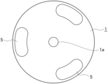
- FIGS. 1 and 2 show shapes of two members of the iron-based green compacts to be bonded by brazing.
- FIG. 1 A is a plan view of a lower member
- FIG. 1 B is a side view of the lower member.
- FIG. 2 A is a plan view of an upper member
- FIG. 2 B is a cross sectional view of the upper member which is taken along line A-A′.
- a lower member 1 with a diameter of 85 mm and a thickness of 3 mm has three columns 5 and a through-hole part 1 a which is arranged at the center.
- Each of the three columns 5 has an upper surface area of 200 mm 2 and a height of 17 mm.
- the upper member with a diameter of 100 mm and a thickness of 10 mm has three through-hole parts 3 and a through-hole part 2 a which is arranged at the center.
- Each of the three through-hole parts 3 has a diameter of 8 mm.
- the lower member 1 and the upper member 2 of the iron-based green compact were combined, and an iron rod 6 covered with Al 2 O 3 was inserted into the central through-hole part to prevent a position displacement.
- the through-hole part 3 of the brazing site was filled with the brazing filler material 4 .
- the iron-based green compact was fired in the ammonia decomposition gas atmosphere at a temperature of 1130° C. for 30 minutes. By firing the iron-based green compact, the iron-based green compact was sintered to become an iron-based sintered compact, and the brazing filler material 4 was melted to braze the lower member 1 and the upper member 2 .
- An ultrasonic inspection was performed by setting the iron-based sintered part on a turntable, moving an ultrasonic sensor in a radial direction while rotating the iron-based sintered compact, and irradiating an upper surface of the brazing site with ultrasonic waves.
- the reflection of the ultrasonic wave is different between a sufficiently brazed portion and a portion where brazing is insufficient, and thus, a brazed area relative to opposite surfaces of the two members can be confirmed.
- a ratio (% by area) of the brazed area to an area obtained by subtracting an area of the through-hole parts 3 of the upper member 2 from an area of the upper surfaces of the columns 5 of the lower member 1 was set as the bonding area ratio.
- Oxidation Oxygen Bonding temperature Oxide concentration area ratio No. (° C.) film (% by mass) (%) 1 No oxidation Non 0.110 40 treatment 2 500 Exist 0.140 75 3 600 Exist 0.142 80 4 700 Exist 0.148 90 5 750 Exist 0.152 100 6 800 Exist 0.164 100 7 850 Exist 0.171 100
- the bonding area ratio was high, and the bonding was able to be performed preferably. As the oxygen concentration of the brazing filler material became high, the bonding area ratio became higher.
- FIGS. 4 A and 4 B Cross sectional SEM (scanning electron microscope) images of the brazing filler materials of Example 1 in which the oxidation treatment was not performed and Example 6 in which the oxidation treatment was performed are shown in FIGS. 4 A and 4 B , respectively.
- FIGS. 4 A and 4 B lower portions are sintered compact portions.
- FIG. 4 B an oxide film layer was observed on a surface layer of the sintered compact portion.
- a cross section of the brazing filler material of Example 6 was observed by using an electron beam microanalyzer “EPMA-1600” produced by Shimadzu Corporation, and an elemental analysis of the oxide film was performed. The results are shown in FIG. 5 .
- FIG. 5 C shows an element analysis image of Mn
- FIG. 5 D shows an element analysis image of Ni
- FIG. 5 E shows an element analysis image of Cu
- FIG. 5 F shows an element analysis image of O.
- a scale on the right side indicates the contrast of the count number.
- no element was observed in a black portion, but as a color became close to white from gray, elements of higher concentration were observed.
- the large amount of Mn and O was observed in the surface layer of the brazing filler material, and it is estimated that a main component of the oxide film on the surface layer of the brazing filler material is MnO. Further, at inside of the brazing filler material, while Mn, Ni, and Cu were distributed in dendritic peripheral bases, no distribution of O was observed.
- the 85.5% of powder containing 40% by mass of Cu, 15% by mass of Mn, 1.5% by mass of Si, 1.5% by mass of B, and a remainder of Ni are blended with 14.5% by mass of Fe powder to prepare a brazing filler material powder having the following composition. 34.2% by mass of Cu, 12.8% by mass of Mn, 14.5% by mass of Fe, 1.54% by mass of Si, 1.28% by mass of B, and a remainder of Ni.
- a predetermined amount of the brazing filler material powder was weighed so that the weight of each sintered compact became 0.66 g and compacting was performed.
- the green compact was fired in the ammonia decomposition gas atmosphere at a temperature of 1120° C. for 30 minutes to obtain the sintered compact. In the firing process, the sintered compact became a spherical body having a diameter of about 6 mm.
- Example 2 to 7 of Production example 1 the oxidation treatment was performed in an experimental small furnace, but in Example 8 of Production example 2, the oxidation treatment was performed in a large furnace for mass production and in a large case.
- Example 8 The oxygen concentration and the bonding area ratio were measured in the similar manner as in Production example 1 described above. The results are shown in Table 2. In Example 8, the oxygen concentration of the brazing filler material became high, and the bonding area ratio was high, and thus, the bonding was able to be performed preferably.
- Example 2 to 7 of Production example 1 described above where the oxidation treatment was performed in the small furnace the brazing filler materials were overlapped with each other, and oxygen is less likely to reach the brazing filler material, and thus, the oxygen concentration after performing the oxidation treatment was limited to some extent, but in Example 8 of Production example 2 where the oxidation treatment was performed in the large furnace, the brazing filler materials were less likely to overlap with each other, and thus, the oxygen concentration became high after the oxidation treatment was performed.
Landscapes
- Chemical & Material Sciences (AREA)
- Engineering & Computer Science (AREA)
- Mechanical Engineering (AREA)
- Materials Engineering (AREA)
- Metallurgy (AREA)
- Organic Chemistry (AREA)
- Composite Materials (AREA)
- Manufacturing & Machinery (AREA)
- Powder Metallurgy (AREA)
Abstract
Description
| TABLE 1 | ||||
| Oxidation | Oxygen | Bonding | ||
| temperature | Oxide | concentration | area ratio | |
| No. | (° C.) | film | (% by mass) | (%) |
| 1 | No oxidation | Non | 0.110 | 40 |
| |
||||
| 2 | 500 | Exist | 0.140 | 75 |
| 3 | 600 | Exist | 0.142 | 80 |
| 4 | 700 | Exist | 0.148 | 90 |
| 5 | 750 | Exist | 0.152 | 100 |
| 6 | 800 | Exist | 0.164 | 100 |
| 7 | 850 | Exist | 0.171 | 100 |
| TABLE 2 | |||||
| Oxygen | |||||
| Oxide | concentration | Bonding | |||
| No. | film | (% by mass) | area ratio (%) | ||
| 8 | Exist | 0.406 | 100 | ||
Claims (9)
Applications Claiming Priority (4)
| Application Number | Priority Date | Filing Date | Title |
|---|---|---|---|
| JPJP2018-190988 | 2018-10-09 | ||
| JP2018190988 | 2018-10-09 | ||
| JP2018-190988 | 2018-10-09 | ||
| PCT/JP2019/039360 WO2020075648A1 (en) | 2018-10-09 | 2019-10-04 | Brazing material for joining iron-based sintered members and method for producing iron-based sintered part |
Publications (2)
| Publication Number | Publication Date |
|---|---|
| US20210339345A1 US20210339345A1 (en) | 2021-11-04 |
| US11623306B2 true US11623306B2 (en) | 2023-04-11 |
Family
ID=70164604
Family Applications (1)
| Application Number | Title | Priority Date | Filing Date |
|---|---|---|---|
| US17/283,818 Active US11623306B2 (en) | 2018-10-09 | 2019-10-04 | Brazing filler material for bonding iron-based sintered member, and method for producing iron-based sintered part |
Country Status (3)
| Country | Link |
|---|---|
| US (1) | US11623306B2 (en) |
| JP (1) | JP7447795B2 (en) |
| WO (1) | WO2020075648A1 (en) |
Citations (9)
| Publication number | Priority date | Publication date | Assignee | Title |
|---|---|---|---|---|
| US4003715A (en) * | 1973-12-21 | 1977-01-18 | A. Johnson & Co. Inc. | Copper-manganese-zinc brazing alloy |
| US4631171A (en) * | 1985-05-16 | 1986-12-23 | Handy & Harman | Copper-zinc-manganese-nickel alloys |
| JPH0215875A (en) * | 1988-07-01 | 1990-01-19 | Sumitomo Electric Ind Ltd | Brazing joining method for iron-based sintered parts |
| US20030062396A1 (en) | 2001-09-28 | 2003-04-03 | Kovacich William L. | Liquid phase sintered braze forms |
| US6605371B1 (en) * | 1998-09-28 | 2003-08-12 | Sumitomo Special Metals Co., Ltd. | Brazing alloy for stainless steel, structure braze-assembled with the brazing alloy, and brazing material for stainless steel |
| JP2009233720A (en) | 2008-03-28 | 2009-10-15 | Hitachi Powdered Metals Co Ltd | Brazing filler metal for joining of iron-based sintered member and joining method of the iron based sintered member |
| JP2011056533A (en) * | 2009-09-09 | 2011-03-24 | Sumitomo Electric Sintered Alloy Ltd | Brazing filler metal for joining sintered component |
| US20120148440A1 (en) * | 2010-12-08 | 2012-06-14 | Kabushiki Kaisha Toyota Chuo Kenkyusho | Copper brazing filler metal |
| US11123825B2 (en) * | 2016-08-31 | 2021-09-21 | Faurecia Emissions Control Technologies, Germany Gmbh | Copper-based brazing material and use of the brazing material |
Family Cites Families (1)
| Publication number | Priority date | Publication date | Assignee | Title |
|---|---|---|---|---|
| JPS63154291A (en) * | 1986-08-05 | 1988-06-27 | Toyota Motor Corp | Brazing filler metal for sintered parts |
-
2019
- 2019-10-04 WO PCT/JP2019/039360 patent/WO2020075648A1/en not_active Ceased
- 2019-10-04 JP JP2020551120A patent/JP7447795B2/en active Active
- 2019-10-04 US US17/283,818 patent/US11623306B2/en active Active
Patent Citations (9)
| Publication number | Priority date | Publication date | Assignee | Title |
|---|---|---|---|---|
| US4003715A (en) * | 1973-12-21 | 1977-01-18 | A. Johnson & Co. Inc. | Copper-manganese-zinc brazing alloy |
| US4631171A (en) * | 1985-05-16 | 1986-12-23 | Handy & Harman | Copper-zinc-manganese-nickel alloys |
| JPH0215875A (en) * | 1988-07-01 | 1990-01-19 | Sumitomo Electric Ind Ltd | Brazing joining method for iron-based sintered parts |
| US6605371B1 (en) * | 1998-09-28 | 2003-08-12 | Sumitomo Special Metals Co., Ltd. | Brazing alloy for stainless steel, structure braze-assembled with the brazing alloy, and brazing material for stainless steel |
| US20030062396A1 (en) | 2001-09-28 | 2003-04-03 | Kovacich William L. | Liquid phase sintered braze forms |
| JP2009233720A (en) | 2008-03-28 | 2009-10-15 | Hitachi Powdered Metals Co Ltd | Brazing filler metal for joining of iron-based sintered member and joining method of the iron based sintered member |
| JP2011056533A (en) * | 2009-09-09 | 2011-03-24 | Sumitomo Electric Sintered Alloy Ltd | Brazing filler metal for joining sintered component |
| US20120148440A1 (en) * | 2010-12-08 | 2012-06-14 | Kabushiki Kaisha Toyota Chuo Kenkyusho | Copper brazing filler metal |
| US11123825B2 (en) * | 2016-08-31 | 2021-09-21 | Faurecia Emissions Control Technologies, Germany Gmbh | Copper-based brazing material and use of the brazing material |
Non-Patent Citations (2)
| Title |
|---|
| Chem Libre; "Chemistry of Manganese." 2020. Aug. 21, 2020. https://chem.libretexts.org/@go/page/644, retrieved from internet on Mar. 9, 2022 (Year: 2020). * |
| EESemi, "Electrode Reduction and Oxidation Potential"; https://www.eesemi.com/ox_potential.htm; retrieved from internet on Mar. 9, 2022 (Year: 2022). * |
Also Published As
| Publication number | Publication date |
|---|---|
| JPWO2020075648A1 (en) | 2021-09-02 |
| WO2020075648A1 (en) | 2020-04-16 |
| US20210339345A1 (en) | 2021-11-04 |
| JP7447795B2 (en) | 2024-03-12 |
Similar Documents
| Publication | Publication Date | Title |
|---|---|---|
| KR101567840B1 (en) | Powder method of manufacturing a component and component | |
| KR100762664B1 (en) | Molybdenum-Copper Powder | |
| KR101101734B1 (en) | Manufacturing method of iron mixed powder and iron powder compact and iron powder sintered compact | |
| EP0187751B1 (en) | Powder mixture free of segregation | |
| JP6297545B2 (en) | High heat conduction valve seat ring | |
| US9334559B2 (en) | Powder, sintered body and sputtering target, each containing elements of Cu, In, Ga and Se, and method for producing the powder | |
| JP5729276B2 (en) | Copper brazing filler metal | |
| EP3118865A1 (en) | Magnetic core, coil component and magnetic core manufacturing method | |
| US9660274B2 (en) | Iron coated chromium powder and SOFC IC made therefrom | |
| JP5073554B2 (en) | Brazing material for joining ferrous sintered members and joining method of ferrous sintered members | |
| CN101516549A (en) | Iron-based powder | |
| US20140331819A1 (en) | Copper alloy for sliding materials | |
| US11623306B2 (en) | Brazing filler material for bonding iron-based sintered member, and method for producing iron-based sintered part | |
| Strauss et al. | Laser additive manufacturing processing of a mixture of iron and nickel powders | |
| KR100475042B1 (en) | Porous agglomerates containing iron and at least one further element from groups 5 or 6 of the periodic table for use as an alloying agent, process for preparing the same, and alloying agent comprising the same | |
| Sundaram | Processing methods for reaching full density powder metallurgical materials | |
| RU2043868C1 (en) | Method to produce sintered pieces from diffusion alloyed iron powders | |
| EP0151185A1 (en) | Tin-containing iron powder and process for its production | |
| US7329380B2 (en) | Method of controlling the dimensional change when sintering an iron-based powder mixture | |
| Zhu et al. | Effect of braze flux on direct laser sintering Cu-based metal powder | |
| JP6690781B2 (en) | Alloy steel powder | |
| EP4269636A1 (en) | Copper alloy powder for additive manufacturing and method for evaluating said copper alloy powder, method for producing copper alloy additively-manufactured article, and copper alloy additively-manufactured article | |
| KR100186931B1 (en) | Method for producing tungsten polymerized gold | |
| JP2026066738A (en) | Metal powder for additive manufacturing, additive products using the same, and methods for manufacturing the same. | |
| JP2024156538A (en) | Copper alloy powder, laminated object using same, and copper alloy molded object made of laminated object |
Legal Events
| Date | Code | Title | Description |
|---|---|---|---|
| AS | Assignment |
Owner name: SHOWA DENKO MATERIALS CO., LTD., JAPAN Free format text: ASSIGNMENT OF ASSIGNORS INTEREST;ASSIGNORS:OHMORI, HIROSHI;YAMANISHI, YUJI;TSUTSUI, TADAYUKI;REEL/FRAME:055867/0643 Effective date: 20201209 |
|
| FEPP | Fee payment procedure |
Free format text: ENTITY STATUS SET TO UNDISCOUNTED (ORIGINAL EVENT CODE: BIG.); ENTITY STATUS OF PATENT OWNER: LARGE ENTITY |
|
| STPP | Information on status: patent application and granting procedure in general |
Free format text: DOCKETED NEW CASE - READY FOR EXAMINATION |
|
| STPP | Information on status: patent application and granting procedure in general |
Free format text: NON FINAL ACTION MAILED |
|
| STPP | Information on status: patent application and granting procedure in general |
Free format text: RESPONSE TO NON-FINAL OFFICE ACTION ENTERED AND FORWARDED TO EXAMINER |
|
| STPP | Information on status: patent application and granting procedure in general |
Free format text: FINAL REJECTION MAILED |
|
| STPP | Information on status: patent application and granting procedure in general |
Free format text: RESPONSE AFTER FINAL ACTION FORWARDED TO EXAMINER |
|
| STPP | Information on status: patent application and granting procedure in general |
Free format text: NOTICE OF ALLOWANCE MAILED -- APPLICATION RECEIVED IN OFFICE OF PUBLICATIONS |
|
| AS | Assignment |
Owner name: RESONAC CORPORATION, JAPAN Free format text: CHANGE OF NAME;ASSIGNOR:SHOWA DENKO MATERIALS CO., LTD.;REEL/FRAME:062992/0805 Effective date: 20230101 |
|
| STCF | Information on status: patent grant |
Free format text: PATENTED CASE |
|
| AS | Assignment |
Owner name: RESONAC CORPORATION, JAPAN Free format text: CHANGE OF ADDRESS;ASSIGNOR:RESONAC CORPORATION;REEL/FRAME:066599/0037 Effective date: 20231001 |