US11620809B2 - Robust fiducial marker for flexible surfaces - Google Patents
Robust fiducial marker for flexible surfaces Download PDFInfo
- Publication number
- US11620809B2 US11620809B2 US16/566,892 US201916566892A US11620809B2 US 11620809 B2 US11620809 B2 US 11620809B2 US 201916566892 A US201916566892 A US 201916566892A US 11620809 B2 US11620809 B2 US 11620809B2
- Authority
- US
- United States
- Prior art keywords
- cells
- area
- dimensional barcode
- corner
- interconnected
- Prior art date
- Legal status (The legal status is an assumption and is not a legal conclusion. Google has not performed a legal analysis and makes no representation as to the accuracy of the status listed.)
- Active, expires
Links
Images


Classifications
-
- G—PHYSICS
- G06—COMPUTING; CALCULATING OR COUNTING
- G06T—IMAGE DATA PROCESSING OR GENERATION, IN GENERAL
- G06T7/00—Image analysis
- G06T7/70—Determining position or orientation of objects or cameras
- G06T7/73—Determining position or orientation of objects or cameras using feature-based methods
- G06T7/74—Determining position or orientation of objects or cameras using feature-based methods involving reference images or patches
-
- G—PHYSICS
- G06—COMPUTING; CALCULATING OR COUNTING
- G06V—IMAGE OR VIDEO RECOGNITION OR UNDERSTANDING
- G06V10/00—Arrangements for image or video recognition or understanding
- G06V10/40—Extraction of image or video features
- G06V10/44—Local feature extraction by analysis of parts of the pattern, e.g. by detecting edges, contours, loops, corners, strokes or intersections; Connectivity analysis, e.g. of connected components
- G06V10/457—Local feature extraction by analysis of parts of the pattern, e.g. by detecting edges, contours, loops, corners, strokes or intersections; Connectivity analysis, e.g. of connected components by analysing connectivity, e.g. edge linking, connected component analysis or slices
-
- G—PHYSICS
- G06—COMPUTING; CALCULATING OR COUNTING
- G06V—IMAGE OR VIDEO RECOGNITION OR UNDERSTANDING
- G06V10/00—Arrangements for image or video recognition or understanding
- G06V10/40—Extraction of image or video features
- G06V10/56—Extraction of image or video features relating to colour
-
- G—PHYSICS
- G06—COMPUTING; CALCULATING OR COUNTING
- G06T—IMAGE DATA PROCESSING OR GENERATION, IN GENERAL
- G06T2207/00—Indexing scheme for image analysis or image enhancement
- G06T2207/10—Image acquisition modality
- G06T2207/10024—Color image
-
- G—PHYSICS
- G06—COMPUTING; CALCULATING OR COUNTING
- G06T—IMAGE DATA PROCESSING OR GENERATION, IN GENERAL
- G06T2207/00—Indexing scheme for image analysis or image enhancement
- G06T2207/30—Subject of image; Context of image processing
- G06T2207/30204—Marker
- G06T2207/30208—Marker matrix
-
- G—PHYSICS
- G06—COMPUTING; CALCULATING OR COUNTING
- G06V—IMAGE OR VIDEO RECOGNITION OR UNDERSTANDING
- G06V10/00—Arrangements for image or video recognition or understanding
- G06V10/20—Image preprocessing
- G06V10/24—Aligning, centring, orientation detection or correction of the image
- G06V10/245—Aligning, centring, orientation detection or correction of the image by locating a pattern; Special marks for positioning
Definitions
- This invention generally relates to visual fiducial marker technology.
- a fiducial marker (also known as tag) is an object placed in the field of view of an imaging system which appears in the image produced, for use as a point of reference or a measure. Such tags are artificial landmarks designed to be easy to recognize and distinguish from one another.
- a fiducial marker system generally includes tags, cameras for capturing images containing these tags, and detection software for detecting and/or identifying these tags.
- Fiducial marker systems have been widely used in applications such as augmented reality, Simultaneous Localization and Mapping (SLAM), human robot interaction, package and human detection and tracking, and factory and warehouse management.
- tags are generally designed as two-dimensional (“2D”) barcodes. When in use, they are attached to or printed on the surface of an object.
- Detection software computes the precise three-dimensional (“3D”) position, orientation, and identity of the tags relative to the camera.
- tags having a square-shaped black border use tags having a square-shaped black border.
- Tag detection is accomplished by detecting square-shaped black border(s) in an image. Once a tag is detected, its payload within the black border is decoded against a database of known tags.
- tags are often attached to or printed on surfaces that may often be warped, bended, or wrinkled. As such, their square-shaped black borders can be easily distorted and lose the square shape, therefore leading to the failure of their detection. This drawback significantly limits the prior art fiducial systems' applications in rough or difficult environments (e.g., applications where tags worn by a human).
- a tag has a square or rectangular shape and is divided into a plurality of cells based on a grid pattern (i.e., arranged in rows and columns).
- the cells are in uniform shape and size and may be in square or rectangular shape.
- Each cell is either dark color or light color. Ideally, black color is used as dark color and white color is used as light color to maximize the success rate of tag detection under real-life lighting conditions of tags, which may not produce ideal images of the tags.
- a cell located along an edge of the tag is called a “border cell”; and a cell not located along any edge of the tag is called an “interior cell.”
- each cell in a first full row of cells along a first edge of the tag being dark color.
- the first full row of cells includes a first corner cell and a second corner cell of the tag.
- the first full row of cells defines a first area of the tag.
- Each cell in a second full row of cells along a second edge of the tag e.g., the bottom edge
- the second full row of cells includes a third corner cell and a fourth corner cell of the tag.
- the second full row of cells defines a second area of the tag.
- the first area and the second area are interconnected by a path of connected cells in dark color, wherein each cell in the path of connected cells is an interior cell.
- Two cells are connected if they share a common cell border and are both in dark color.
- the remaining cells of the plurality of cells are either dark color or light color.
- the present invention detects the four corner cells first in the image. If the four corner cells are detected, the present invention determines whether the first and second corner cells are interconnected in the first area in the image and whether the third and fourth corner cells are interconnected in the second area in the image. If so, the present invention determines whether the first area and the second area are interconnected by a path of connected dark interior cells in the image. If the first area and the second area are interconnected by a path of connected dark interior cells in the image, the tag is detected in the image and the present invention tries to decode the tag in the image.
- the path of connected dark interior cells form a straight line.
- the four corner cells are interconnected by multiple paths of connected dark cells.
- the present invention first detects the four corner cells in the image.
- the present invention determines whether the four corner cells are interconnected by paths containing connected dark cells in the image. If so, the tag is detected in the image and the present invention then tries to decode the tag in the image.
- FIG. 1 A illustrates a prior art tag design
- FIG. 1 B illustrates an example of a prior art tag.
- FIG. 1 C illustrates a problem with the prior art tag design illustrated in FIG. 1 A .
- FIG. 1 D illustrates another problem with the prior art tag design illustrated in FIG. 1 A .
- FIG. 2 A illustrates a tag design, according to one embodiment of the present invention.
- FIG. 2 B illustrates an example of a tag, according to one embodiment of the present invention.
- FIG. 3 illustrates a process of detecting a tag, according to one embodiment of the present invention.
- FIG. 4 A illustrates how the tag design in FIG. 2 A can void the problem illustrated in FIG. 1 C .
- FIG. 4 B illustrates how the tag design in FIG. 2 A can mitigate the problem illustrated in FIG. 1 D .
- FIG. 5 A illustrates a tag design, according to one embodiment of the present invention.
- FIG. 5 B illustrates an example of a tag, according to one embodiment of the present invention.
- FIG. 6 A illustrates a tag design, according to one embodiment of the present invention.
- FIG. 6 B illustrates an example of a tag, according to one embodiment of the present invention.
- FIG. 7 illustrates a tag design, according to one embodiment of the present invention.
- FIG. 8 A illustrates a tag design, according to one embodiment of the present invention.
- FIG. 8 B illustrates an example of a tag, according to one embodiment of the present invention.
- FIG. 9 illustrates a process of detecting a tag, according to one embodiment of the present invention.
- FIG. 1 A illustrates a prior art tag design.
- the prior art tag design embodies a square-shaped 8 ⁇ 8 grid, having a total of 64 square units (a.k.a., cells). Each square unit is either in black color or white color.
- the border section 101 (the hatched section shown in FIG. 1 A ) is always in black color for tag detection. If the detection software cannot detect the square-shaped black border in an image containing the tag, the tag is not detected. Detection is generally accomplished by computer vision algorithms, such as Union-find for boundary detection and principal component analysis (PCA) for corner detection.
- PCA principal component analysis
- the dotted section 102 is used for coding, e.g., by assigning black or white color to each square unit.
- FIG. 1 B illustrates an example of a tag according to this prior art design.
- FIG. 1 C illustrates such a problem where the tag shown in FIG. 1 B is warped such that the square-shaped black border captured in an image is not square-shaped anymore.
- the detection software reconstruct the square-shaped border by simply adjusting the view point because the tag itself has warped. This could happen when the tag is printed on or attached to a soft or uneven surface which may be warped, stretched, distorted, or wrinkled frequently.
- some tags are printed or attached on workers' uniforms or clothes. When a worker moves around, the tag on his/her uniform can get easily warped, stretched, or distorted. As a result, the detection software won't be able to detect the tag. If this kind of failure happens too often and widespread, the whole system may stop working properly.
- FIG. 1 D illustrates another problem with the prior art tag design illustrated in FIG. 1 A .
- the tag's square-shaped black border is partially covered by a person's thumb. The thumb breaks the closed loop of the border, and if any portion of the square-shaped black border is blocked or covered, the detection software will not be able to detect the tag. Because the border section 101 (shown in FIG. 1 A ) takes up 7/16 of the total tag area, the probability that the border section of the tag is blocked or covered compared to the probability that the coding section 102 (shown in FIG. 1 A ) is covered or blocked by an object is 7 to 9.
- the ratio should be even higher because when the coding section 102 is blocked or covered by an object (e.g., a hand), the border section is also likely blocked or covered by the same object or any extension of the object (e.g., forearm). As such, the prior art tag design illustrated in FIG. 1 A is prone to detection failure.
- an object e.g., a hand
- the border section is also likely blocked or covered by the same object or any extension of the object (e.g., forearm).
- the prior art tag design illustrated in FIG. 1 A is prone to detection failure.
- FIG. 2 A illustrates a new tag design, according to one embodiment of the present invention.
- the new tag design embodies a rectangular-shaped 8 ⁇ 7 grid, including 56 square units or cells.
- Section 201 (the hatched area) is a full row of square units (including two corner square units) along the top edge of the tag. It contains 7 square units.
- Section 202 (the crosshatched area) is a full row of square units (including the other two corner square units) along the bottom edge of the tag.
- Section 202 contains 7 square units.
- the top edge is opposite to the bottom edge.
- the middle column, namely section 203 (the dotted area) contains 6 square units.
- Section 201 , section 202 and section 203 (collectively, “the detection area”) are always in black color.
- the detection area is used for tag detection. Specifically, the detection method is to check whether the detection area is interconnected, meaning that it is in continuous black color. This design is more effective and robust in dealing with rough or difficult to control environments.
- the remaining section contains 36 square units and is used for coding. And each of the remaining 36 square units is either black color or white color. It should be noted that although descriptions of the embodiments in the present application use black and white colors for the square units (or cells), other dark and light colors may also be used as long as they have adequate contrast and can be distinguished in an image by processing software.
- the 8 ⁇ 7 grid is used for explaining the embodiment only. Other grid patterns may be used as well.
- the shape of a tag may be square or rectangular, and the tags may have various numbers of rows, columns, and square units.
- FIG. 2 B illustrates an example of a tag according to the design illustrated in FIG. 2 A .
- the top and bottom rows are in black color and there is a middle column which is also in black color.
- the two top corner cells are interconnected by black cells in the top row.
- the two bottom corner cells are interconnected by black cells in the bottom row.
- the top and bottom rows are interconnected by black cells of the middle column. Patterns formed by black and white cells are configured in coding areas.
- a tag may be placed with different orientation settings and may also be rotated sometimes. For instance, if the tag shown in FIG. 2 B is rotated by ninety degrees anticlockwise, the top and bottom rows become the left and right columns and the middle column becomes a middle row.
- the orientation change doesn't affect detection of a tag, since the viewpoint may be adjusted by processing software.
- FIG. 3 illustrates a process 300 of detecting a tag, such as one following the design illustrated in FIG. 2 A .
- a system for using a tag may include the tag, a working camera, and a processing unit (e.g., a computer) having software or program containing instructions for detecting and decoding the tag.
- the tag is attached to a target object.
- the process 300 receives an image of the tag captured by the working camera. As shown in FIGS. 1 C and 1 D , the tag could be warped or occluded.
- the process 300 scans the image to find the four corners of the tag, which should be in black color.
- Various computer vision algorithms may be used for finding the four corners.
- the process 300 may use Harris corner detector to detect the four corners of the tag (e.g., the outermost four corners of all corners detected from the tag image). If the four corners are detected, then the process goes to step 303 . Otherwise, tag detection fails and the process reports failure.
- the process 300 scans the image to determine whether the detection area (as defined in FIG. 2 A ) is interconnected in black color. Specifically, the process 300 determines whether two of the four tag corners are interconnected along the path of the square units of section 201 of the tag (as shown in FIG. 2 A ).
- interconnection does not require that all 7 square units of section 201 be identified, in perfect alignment, or square-shaped in the image. Rather, interconnection is achieved when the square units of section 201 of the tag identified from the image (whether all 7 of them or part of them) together with the two tag corners are interconnected in black color.
- the process 300 determines whether the other two tag corners are interconnected along the path of the square units of section 202 of the detection area (also shown in FIG. 2 A ) and whether the two sections 201 and 202 are interconnected along the path of the square units of section 203 (also shown in FIG. 2 A ). If the detection area is not interconnected, then the process reports failure. Otherwise, the tag is detected, and the process goes to step 304 , where the tag is decoded.
- FIG. 4 A illustrates how the design in FIG. 2 A can void the problem illustrated in FIG. 1 C .
- the tag in FIG. 4 A is warped, similar to the example shown in FIG. 1 C .
- the tag's detection area is still interconnected. As such, the tag in FIG. 4 A can still be detected, whereas the tag in FIG. 1 C could not be detected by the prior art method.
- FIG. 4 B illustrates how the design in FIG. 2 A can mitigate the problem illustrated in FIG. 1 D . Similar to the example in FIG. 1 D , the right edge of the tag in FIG. 4 B is covered by a person's thumb. However, this won't affect the detection of the tag in FIG. 4 B because the detection area of the tag is still interconnected.
- the detection software may still be able to do a partial decoding and narrow down the results to a small range or number of codes. Based on other available information, such as the tag's current location and other tags' historical location data, the system may further narrow down the range or number of codes.
- Another advantage of the tag design illustrated in FIG. 2 A is that its coding area to total tag area ratio is 9:14, which is better than that of the prior art design.
- the coding area is the same, the overall size of the new design is smaller than that of the prior art design.
- FIG. 5 A illustrates another tag design, according to one embodiment of the present invention.
- the design is similar to the design illustrated in FIG. 2 A .
- the middle column of square units (section 203 in FIG. 2 A ) as a designated area for detection purposes, the middle column of square units is now used for coding as well. This further improves the coding area to total tag area ratio to 3:4 or 75%.
- sections 501 and 502 are still designated for detection purposes.
- the coding area should have at least one path of connected square units interconnecting section 501 and section 502 .
- two square units are connected if the two square units are all in black color and share a common border.
- the detection method here is to check whether there is at least one path of connected square units interconnecting section 501 and section 502 .
- the design in FIG. 5 A is more flexible and robust. In addition, it has more coding space than the design in FIG. 2 A does.
- FIG. 5 B illustrates an example of a tag, according to one embodiment of the present invention.
- a modified version of the process 300 may be used for detecting a tag according to the design illustrated in FIG. 5 A .
- the modified version of the process 300 still scans a tag image to identify the four corners. Then, the modified process determines whether two corners are interconnected along the path of the square units of section 501 and whether the other two corners are interconnected along the path of the square units of section 502 . Like the process 300 , the modified process determines whether there is at least one path of connected square units (or connected black cells) that interconnects section 501 and section 502 . If any of the above steps fails, the detection process reports detection failure and abort the detection process.
- a thin white color border 601 is added around the tag.
- the width of the white color border 601 is about 1 ⁇ 3 of the width of the square.
- This white color border creates a sharp contrast with the designated detection area 602 of the tag and makes it easier for detection.
- FIG. 6 B illustrates an example of a fiducial marker, according to one embodiment of the present invention.
- the background 603 may have a color too close to the color of the designated detection area 602 . Adding a thin white color border 601 would create a sharp contrast between the designated detection area 602 and the thin white color border 601 so that it is easier to detect the designated detection area 602 .
- FIG. 7 illustrates another embodiment of the present invention based on the embodiment shown in FIG. 2 A .
- a five-digit code (each digit may be a number or a letter) is added to the bottom of the tag and part of the digits overlap with the square units in section 202 .
- a portion of an image of the code is presented using the bottom row of the tag.
- a portion of the image may also be presented using the top row of the tag.
- the top and bottom rows may be used to present two codes for a tag.
- the five-digit code provides an additional means for error correction on the tag's code. It also provides a convenient way of identification by human eyes.
- the five-digit code if the tag's code cannot be completely identified due to, for example, part of the coding area is covered (as illustrated in FIG. 4 B ), the five-digit code, if can be detected and identified by the detection software, can help to further identifies the tag's code.
- the dimension of a digit number/letter is roughly 1 ⁇ 11 ⁇ 3 of a square unit so the recognition range for the digit number/letter is comparable to 1 ⁇ 2 of the marker in the best case.
- the five-digit code may be recognized by deep leaning algorithms, which provide robust error corrections when the recognition confidence level of traditional computer vision based marker recognition is low.
- the code could be four or other number of digits as well depending on the application.
- the code may contain one or more elements. The elements may include a numerical number, a letter, a character, or a symbol.
- FIG. 8 A illustrates another tag design, according to yet another embodiment of the present invention.
- the four corner square units 801 , 802 , 803 , and 804 are always in black color.
- this design requires that the four corner square units 801 - 804 be interconnected by other black square units in the tag.
- FIG. 8 B illustrates a valid tag under the design illustrated by FIG. 8 A .
- This design further increases the coding space of the tag.
- this tag design improves the robustness for detection because it does not depend on whether a specific detection area can be identified from an image. As such, it can deal with warped or uneven surface better than the above disclosed embodiments.
- a thin border region in white or light color may be placed around the tag shown in FIGS. 8 A and 8 B .
- the thin border region creates a sharp contrast with the corners of the tag and makes it easier for detection.
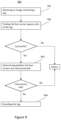
- FIG. 9 illustrates a process 900 of detecting a tag, such as one following the design illustrated in FIG. 8 A .
- the process 900 receives an image of a tag captured by a working camera. As shown in FIGS. 1 C and 1 D , the tag could be warped or occluded.
- the process 900 scans the image to find the four corners of the tag, which should be in black color.
- Various computer vision algorithms may be used for finding the four corners.
- the process 900 may use Harris corner detector to detect the four corners of the tag. If the four corners are detected, then the process goes to step 903 . Otherwise, tag detection fails and the process reports failure.
- the process 300 scans the image to determine whether the four corners are interconnected in black color.
- One way to determine whether the four corners are interconnected is to determine whether there is at least one path of connected square units from one tag corner to the other three tag corners. If the detection area is not interconnected, then the process reports failure. Otherwise, the tag is detected, and the process goes to step 904 , where the tag is decoded.
Abstract
Description
Claims (15)
Priority Applications (1)
| Application Number | Priority Date | Filing Date | Title |
|---|---|---|---|
| US16/566,892 US11620809B2 (en) | 2018-09-11 | 2019-09-11 | Robust fiducial marker for flexible surfaces |
Applications Claiming Priority (2)
| Application Number | Priority Date | Filing Date | Title |
|---|---|---|---|
| US201862729427P | 2018-09-11 | 2018-09-11 | |
| US16/566,892 US11620809B2 (en) | 2018-09-11 | 2019-09-11 | Robust fiducial marker for flexible surfaces |
Publications (2)
| Publication Number | Publication Date |
|---|---|
| US20200082200A1 US20200082200A1 (en) | 2020-03-12 |
| US11620809B2 true US11620809B2 (en) | 2023-04-04 |
Family
ID=69719879
Family Applications (1)
| Application Number | Title | Priority Date | Filing Date |
|---|---|---|---|
| US16/566,892 Active 2039-12-28 US11620809B2 (en) | 2018-09-11 | 2019-09-11 | Robust fiducial marker for flexible surfaces |
Country Status (1)
| Country | Link |
|---|---|
| US (1) | US11620809B2 (en) |
Families Citing this family (1)
| Publication number | Priority date | Publication date | Assignee | Title |
|---|---|---|---|---|
| US10817764B2 (en) * | 2018-09-21 | 2020-10-27 | Beijing Jingdong Shangke Information Technology Co., Ltd. | Robot system for processing an object and method of packaging and processing the same |
Citations (2)
| Publication number | Priority date | Publication date | Assignee | Title |
|---|---|---|---|---|
| US20170193260A1 (en) * | 2015-03-30 | 2017-07-06 | Temptime Corporation | Two dimensional barcode with dynamic environmental data system, method, and apparatus |
| US9727811B2 (en) * | 2014-06-19 | 2017-08-08 | Samsung Pay, Inc. | Methods and apparatus for barcode reading and encoding |
-
2019
- 2019-09-11 US US16/566,892 patent/US11620809B2/en active Active
Patent Citations (2)
| Publication number | Priority date | Publication date | Assignee | Title |
|---|---|---|---|---|
| US9727811B2 (en) * | 2014-06-19 | 2017-08-08 | Samsung Pay, Inc. | Methods and apparatus for barcode reading and encoding |
| US20170193260A1 (en) * | 2015-03-30 | 2017-07-06 | Temptime Corporation | Two dimensional barcode with dynamic environmental data system, method, and apparatus |
Non-Patent Citations (2)
| Title |
|---|
| Walters, Austin, and Bhargava Manja. "ChromaTag-A Colored Fiducial Marker." Internet: https://github. com/lettergram/chromatag, May 16 (2015).http://108.61.119.12/wp-content/uploads/2015/05/cs543_Final-chromatags-awalte9-manja2.pdf (Year: 2015). * |
| Wang, John, and Edwin Olson. "AprilTag 2: Efficient and robust fiducial detection." 2016 IEEE/RSJ International Conference on Intelligent Robots and Systems (IROS). IEEE, 2016. https://ieeexplore.ieee.org/stamp/stamp.jsp?tp=&arnumber=7759617 (Year: 2016). * |
Also Published As
| Publication number | Publication date |
|---|---|
| US20200082200A1 (en) | 2020-03-12 |
Similar Documents
| Publication | Publication Date | Title |
|---|---|---|
| US11455482B2 (en) | Systems and methods for decoding two-dimensional matrix symbols with incomplete or absent fixed patterns | |
| Fiala | Designing highly reliable fiducial markers | |
| US10438036B1 (en) | System and method for reading and decoding ID codes on a curved, sloped and/or annular object | |
| JP5414685B2 (en) | System and method for reading a pattern using a plurality of image frames | |
| US20120145779A1 (en) | Two-dimensional symbol code and method for reading the symbol code | |
| US11948042B2 (en) | System and method for configuring an ID reader using a mobile device | |
| US20040028258A1 (en) | Fiducial detection system | |
| KR100698534B1 (en) | Landmark for location recognition of mobile robot and location recognition device and method using same | |
| US9946947B2 (en) | System and method for finding saddle point-like structures in an image and determining information from the same | |
| TW201339975A (en) | Barcode recognition method and a computer product thereof | |
| CN105512530A (en) | Biometric information correcting apparatus and biometric information correcting method | |
| CN101339604B (en) | Novel mark point graph and its recognition, tracking and positioning algorithm based on visual sense invariance | |
| US11620809B2 (en) | Robust fiducial marker for flexible surfaces | |
| CN110502948B (en) | Restoration method and device for folding two-dimensional code image and code scanning equipment | |
| WO2023193763A1 (en) | Data processing method and apparatus, and tracking mark, electronic device and storage medium | |
| Wang | LFTag: A scalable visual fiducial system with low spatial frequency | |
| Fiala | Artag fiducial marker system applied to vision based spacecraft docking | |
| US20200250855A1 (en) | Fiducial Marker Based on Blocks of Different Grayscales | |
| CN111179347B (en) | Positioning method, positioning equipment and storage medium based on regional characteristics | |
| Nakamura et al. | Multi-agent-based Two-dimensional Barcode Decoding Robust against Non-uniform Geometric Distortion. | |
| US20210192256A1 (en) | Method for optical recognition of markers | |
| CN109976590B (en) | Camera-based touch detection method | |
| US10796183B2 (en) | Fiducial marker, method for forming the fiducial marker, and system for sensing thereof | |
| Tsoy et al. | Recommended Criteria for Qualitative Comparison of Fiducial Markers Performance | |
| US20230394704A1 (en) | Optically Readable Markers |
Legal Events
| Date | Code | Title | Description |
|---|---|---|---|
| FEPP | Fee payment procedure |
Free format text: ENTITY STATUS SET TO UNDISCOUNTED (ORIGINAL EVENT CODE: BIG.); ENTITY STATUS OF PATENT OWNER: SMALL ENTITY |
|
| FEPP | Fee payment procedure |
Free format text: ENTITY STATUS SET TO SMALL (ORIGINAL EVENT CODE: SMAL); ENTITY STATUS OF PATENT OWNER: SMALL ENTITY |
|
| STPP | Information on status: patent application and granting procedure in general |
Free format text: NON FINAL ACTION MAILED |
|
| STPP | Information on status: patent application and granting procedure in general |
Free format text: RESPONSE TO NON-FINAL OFFICE ACTION ENTERED AND FORWARDED TO EXAMINER |
|
| STPP | Information on status: patent application and granting procedure in general |
Free format text: FINAL REJECTION MAILED |
|
| STPP | Information on status: patent application and granting procedure in general |
Free format text: DOCKETED NEW CASE - READY FOR EXAMINATION |
|
| STPP | Information on status: patent application and granting procedure in general |
Free format text: NON FINAL ACTION MAILED |
|
| STPP | Information on status: patent application and granting procedure in general |
Free format text: RESPONSE TO NON-FINAL OFFICE ACTION ENTERED AND FORWARDED TO EXAMINER |
|
| STPP | Information on status: patent application and granting procedure in general |
Free format text: FINAL REJECTION MAILED |
|
| STPP | Information on status: patent application and granting procedure in general |
Free format text: RESPONSE AFTER FINAL ACTION FORWARDED TO EXAMINER |
|
| STPP | Information on status: patent application and granting procedure in general |
Free format text: ADVISORY ACTION MAILED |
|
| STPP | Information on status: patent application and granting procedure in general |
Free format text: DOCKETED NEW CASE - READY FOR EXAMINATION |
|
| STPP | Information on status: patent application and granting procedure in general |
Free format text: NOTICE OF ALLOWANCE MAILED -- APPLICATION RECEIVED IN OFFICE OF PUBLICATIONS |
|
| STCF | Information on status: patent grant |
Free format text: PATENTED CASE |