US11617705B2 - Robotic assistant and method for controlling the same - Google Patents
Robotic assistant and method for controlling the same Download PDFInfo
- Publication number
- US11617705B2 US11617705B2 US17/530,501 US202117530501A US11617705B2 US 11617705 B2 US11617705 B2 US 11617705B2 US 202117530501 A US202117530501 A US 202117530501A US 11617705 B2 US11617705 B2 US 11617705B2
- Authority
- US
- United States
- Prior art keywords
- seat
- actuator
- foldable seat
- robotic assistant
- user
- Prior art date
- Legal status (The legal status is an assumption and is not a legal conclusion. Google has not performed a legal analysis and makes no representation as to the accuracy of the status listed.)
- Active
Links
Images


Classifications
-
- A—HUMAN NECESSITIES
- A61—MEDICAL OR VETERINARY SCIENCE; HYGIENE
- A61H—PHYSICAL THERAPY APPARATUS, e.g. DEVICES FOR LOCATING OR STIMULATING REFLEX POINTS IN THE BODY; ARTIFICIAL RESPIRATION; MASSAGE; BATHING DEVICES FOR SPECIAL THERAPEUTIC OR HYGIENIC PURPOSES OR SPECIFIC PARTS OF THE BODY
- A61H3/00—Appliances for aiding patients or disabled persons to walk about
- A61H3/04—Wheeled walking aids for disabled persons
-
- B—PERFORMING OPERATIONS; TRANSPORTING
- B25—HAND TOOLS; PORTABLE POWER-DRIVEN TOOLS; MANIPULATORS
- B25J—MANIPULATORS; CHAMBERS PROVIDED WITH MANIPULATION DEVICES
- B25J11/00—Manipulators not otherwise provided for
- B25J11/008—Manipulators for service tasks
-
- B—PERFORMING OPERATIONS; TRANSPORTING
- B25—HAND TOOLS; PORTABLE POWER-DRIVEN TOOLS; MANIPULATORS
- B25J—MANIPULATORS; CHAMBERS PROVIDED WITH MANIPULATION DEVICES
- B25J5/00—Manipulators mounted on wheels or on carriages
- B25J5/007—Manipulators mounted on wheels or on carriages mounted on wheels
-
- A—HUMAN NECESSITIES
- A61—MEDICAL OR VETERINARY SCIENCE; HYGIENE
- A61H—PHYSICAL THERAPY APPARATUS, e.g. DEVICES FOR LOCATING OR STIMULATING REFLEX POINTS IN THE BODY; ARTIFICIAL RESPIRATION; MASSAGE; BATHING DEVICES FOR SPECIAL THERAPEUTIC OR HYGIENIC PURPOSES OR SPECIFIC PARTS OF THE BODY
- A61H3/00—Appliances for aiding patients or disabled persons to walk about
- A61H3/04—Wheeled walking aids for disabled persons
- A61H2003/043—Wheeled walking aids for disabled persons with a drive mechanism
-
- A—HUMAN NECESSITIES
- A61—MEDICAL OR VETERINARY SCIENCE; HYGIENE
- A61H—PHYSICAL THERAPY APPARATUS, e.g. DEVICES FOR LOCATING OR STIMULATING REFLEX POINTS IN THE BODY; ARTIFICIAL RESPIRATION; MASSAGE; BATHING DEVICES FOR SPECIAL THERAPEUTIC OR HYGIENIC PURPOSES OR SPECIFIC PARTS OF THE BODY
- A61H2201/00—Characteristics of apparatus not provided for in the preceding codes
- A61H2201/01—Constructive details
- A61H2201/0161—Size reducing arrangements when not in use, for stowing or transport
-
- A—HUMAN NECESSITIES
- A61—MEDICAL OR VETERINARY SCIENCE; HYGIENE
- A61H—PHYSICAL THERAPY APPARATUS, e.g. DEVICES FOR LOCATING OR STIMULATING REFLEX POINTS IN THE BODY; ARTIFICIAL RESPIRATION; MASSAGE; BATHING DEVICES FOR SPECIAL THERAPEUTIC OR HYGIENIC PURPOSES OR SPECIFIC PARTS OF THE BODY
- A61H2201/00—Characteristics of apparatus not provided for in the preceding codes
- A61H2201/01—Constructive details
- A61H2201/0165—Damping, vibration related features
-
- A—HUMAN NECESSITIES
- A61—MEDICAL OR VETERINARY SCIENCE; HYGIENE
- A61H—PHYSICAL THERAPY APPARATUS, e.g. DEVICES FOR LOCATING OR STIMULATING REFLEX POINTS IN THE BODY; ARTIFICIAL RESPIRATION; MASSAGE; BATHING DEVICES FOR SPECIAL THERAPEUTIC OR HYGIENIC PURPOSES OR SPECIFIC PARTS OF THE BODY
- A61H2201/00—Characteristics of apparatus not provided for in the preceding codes
- A61H2201/01—Constructive details
- A61H2201/0192—Specific means for adjusting dimensions
-
- A—HUMAN NECESSITIES
- A61—MEDICAL OR VETERINARY SCIENCE; HYGIENE
- A61H—PHYSICAL THERAPY APPARATUS, e.g. DEVICES FOR LOCATING OR STIMULATING REFLEX POINTS IN THE BODY; ARTIFICIAL RESPIRATION; MASSAGE; BATHING DEVICES FOR SPECIAL THERAPEUTIC OR HYGIENIC PURPOSES OR SPECIFIC PARTS OF THE BODY
- A61H2201/00—Characteristics of apparatus not provided for in the preceding codes
- A61H2201/12—Driving means
- A61H2201/1207—Driving means with electric or magnetic drive
- A61H2201/123—Linear drive
-
- A—HUMAN NECESSITIES
- A61—MEDICAL OR VETERINARY SCIENCE; HYGIENE
- A61H—PHYSICAL THERAPY APPARATUS, e.g. DEVICES FOR LOCATING OR STIMULATING REFLEX POINTS IN THE BODY; ARTIFICIAL RESPIRATION; MASSAGE; BATHING DEVICES FOR SPECIAL THERAPEUTIC OR HYGIENIC PURPOSES OR SPECIFIC PARTS OF THE BODY
- A61H2201/00—Characteristics of apparatus not provided for in the preceding codes
- A61H2201/16—Physical interface with patient
- A61H2201/1602—Physical interface with patient kind of interface, e.g. head rest, knee support or lumbar support
- A61H2201/1628—Pelvis
- A61H2201/1633—Seat
-
- A—HUMAN NECESSITIES
- A61—MEDICAL OR VETERINARY SCIENCE; HYGIENE
- A61H—PHYSICAL THERAPY APPARATUS, e.g. DEVICES FOR LOCATING OR STIMULATING REFLEX POINTS IN THE BODY; ARTIFICIAL RESPIRATION; MASSAGE; BATHING DEVICES FOR SPECIAL THERAPEUTIC OR HYGIENIC PURPOSES OR SPECIFIC PARTS OF THE BODY
- A61H2201/00—Characteristics of apparatus not provided for in the preceding codes
- A61H2201/16—Physical interface with patient
- A61H2201/1602—Physical interface with patient kind of interface, e.g. head rest, knee support or lumbar support
- A61H2201/1635—Hand or arm, e.g. handle
-
- A—HUMAN NECESSITIES
- A61—MEDICAL OR VETERINARY SCIENCE; HYGIENE
- A61H—PHYSICAL THERAPY APPARATUS, e.g. DEVICES FOR LOCATING OR STIMULATING REFLEX POINTS IN THE BODY; ARTIFICIAL RESPIRATION; MASSAGE; BATHING DEVICES FOR SPECIAL THERAPEUTIC OR HYGIENIC PURPOSES OR SPECIFIC PARTS OF THE BODY
- A61H2201/00—Characteristics of apparatus not provided for in the preceding codes
- A61H2201/16—Physical interface with patient
- A61H2201/1657—Movement of interface, i.e. force application means
- A61H2201/1659—Free spatial automatic movement of interface within a working area, e.g. Robot
-
- A—HUMAN NECESSITIES
- A61—MEDICAL OR VETERINARY SCIENCE; HYGIENE
- A61H—PHYSICAL THERAPY APPARATUS, e.g. DEVICES FOR LOCATING OR STIMULATING REFLEX POINTS IN THE BODY; ARTIFICIAL RESPIRATION; MASSAGE; BATHING DEVICES FOR SPECIAL THERAPEUTIC OR HYGIENIC PURPOSES OR SPECIFIC PARTS OF THE BODY
- A61H2201/00—Characteristics of apparatus not provided for in the preceding codes
- A61H2201/16—Physical interface with patient
- A61H2201/1657—Movement of interface, i.e. force application means
- A61H2201/1671—Movement of interface, i.e. force application means rotational
-
- A—HUMAN NECESSITIES
- A61—MEDICAL OR VETERINARY SCIENCE; HYGIENE
- A61H—PHYSICAL THERAPY APPARATUS, e.g. DEVICES FOR LOCATING OR STIMULATING REFLEX POINTS IN THE BODY; ARTIFICIAL RESPIRATION; MASSAGE; BATHING DEVICES FOR SPECIAL THERAPEUTIC OR HYGIENIC PURPOSES OR SPECIFIC PARTS OF THE BODY
- A61H2201/00—Characteristics of apparatus not provided for in the preceding codes
- A61H2201/50—Control means thereof
- A61H2201/5007—Control means thereof computer controlled
-
- A—HUMAN NECESSITIES
- A61—MEDICAL OR VETERINARY SCIENCE; HYGIENE
- A61H—PHYSICAL THERAPY APPARATUS, e.g. DEVICES FOR LOCATING OR STIMULATING REFLEX POINTS IN THE BODY; ARTIFICIAL RESPIRATION; MASSAGE; BATHING DEVICES FOR SPECIAL THERAPEUTIC OR HYGIENIC PURPOSES OR SPECIFIC PARTS OF THE BODY
- A61H2201/00—Characteristics of apparatus not provided for in the preceding codes
- A61H2201/50—Control means thereof
- A61H2201/5023—Interfaces to the user
- A61H2201/5043—Displays
- A61H2201/5046—Touch screens
-
- A—HUMAN NECESSITIES
- A61—MEDICAL OR VETERINARY SCIENCE; HYGIENE
- A61H—PHYSICAL THERAPY APPARATUS, e.g. DEVICES FOR LOCATING OR STIMULATING REFLEX POINTS IN THE BODY; ARTIFICIAL RESPIRATION; MASSAGE; BATHING DEVICES FOR SPECIAL THERAPEUTIC OR HYGIENIC PURPOSES OR SPECIFIC PARTS OF THE BODY
- A61H2201/00—Characteristics of apparatus not provided for in the preceding codes
- A61H2201/50—Control means thereof
- A61H2201/5058—Sensors or detectors
- A61H2201/5061—Force sensors
-
- A—HUMAN NECESSITIES
- A61—MEDICAL OR VETERINARY SCIENCE; HYGIENE
- A61H—PHYSICAL THERAPY APPARATUS, e.g. DEVICES FOR LOCATING OR STIMULATING REFLEX POINTS IN THE BODY; ARTIFICIAL RESPIRATION; MASSAGE; BATHING DEVICES FOR SPECIAL THERAPEUTIC OR HYGIENIC PURPOSES OR SPECIFIC PARTS OF THE BODY
- A61H2201/00—Characteristics of apparatus not provided for in the preceding codes
- A61H2201/50—Control means thereof
- A61H2201/5058—Sensors or detectors
- A61H2201/5064—Position sensors
- A61H2201/5066—Limit switches
-
- A—HUMAN NECESSITIES
- A61—MEDICAL OR VETERINARY SCIENCE; HYGIENE
- A61H—PHYSICAL THERAPY APPARATUS, e.g. DEVICES FOR LOCATING OR STIMULATING REFLEX POINTS IN THE BODY; ARTIFICIAL RESPIRATION; MASSAGE; BATHING DEVICES FOR SPECIAL THERAPEUTIC OR HYGIENIC PURPOSES OR SPECIFIC PARTS OF THE BODY
- A61H2201/00—Characteristics of apparatus not provided for in the preceding codes
- A61H2201/50—Control means thereof
- A61H2201/5058—Sensors or detectors
- A61H2201/5092—Optical sensor
-
- A—HUMAN NECESSITIES
- A61—MEDICAL OR VETERINARY SCIENCE; HYGIENE
- A61H—PHYSICAL THERAPY APPARATUS, e.g. DEVICES FOR LOCATING OR STIMULATING REFLEX POINTS IN THE BODY; ARTIFICIAL RESPIRATION; MASSAGE; BATHING DEVICES FOR SPECIAL THERAPEUTIC OR HYGIENIC PURPOSES OR SPECIFIC PARTS OF THE BODY
- A61H2203/00—Additional characteristics concerning the patient
- A61H2203/04—Position of the patient
- A61H2203/0406—Standing on the feet
-
- G—PHYSICS
- G02—OPTICS
- G02B—OPTICAL ELEMENTS, SYSTEMS OR APPARATUS
- G02B27/00—Optical systems or apparatus not provided for by any of the groups G02B1/00 - G02B26/00, G02B30/00
- G02B27/01—Head-up displays
- G02B27/0179—Display position adjusting means not related to the information to be displayed
Definitions
- the present disclosure generally relates to robots, and particularly to a smart robotic assistant that can provide walking assistance, walking training, and body training.
- one type of a robotic assistant can be designed to help support a portion of the user's bodyweight to reduce the load on the user's legs while walking, leading to reduced fatigue and less physical exertion.
- a robotic assistant can be designed to help support a portion of the user's bodyweight to reduce the load on the user's legs while walking, leading to reduced fatigue and less physical exertion.
- assistive robots including the applications for the upper limb, for the lower limb and for the assisting or training of the whole body.
- robotic assistants typically include wheels for movement and a vertical body having handles for users to grip. Some of the robotic assistants may include a seat that allows a user to sit thereon.
- these robotic assistants are humanoid, which focus on the virtual or psychological interaction with people without addressing too much on the physical interaction, making it difficult to provide a better a human-robot interaction.
- FIG. 2 is a schematic isometric view of the robotic assistant, with certain components omitted for clarity.
- FIG. 3 a is similar to FIG. 2 , but viewed from a different perspective.
- FIG. 4 is an enlarged view of a portion A of FIG. 3 a.
- FIG. 5 is an enlarged view of a portion B of FIG. 3 a.
- FIG. 6 is a schematic diagram showing the display in two different positions.
- FIG. 8 is a schematic flowchart of a method for controlling the robotic assistant according to one embodiment.
- FIG. 10 shows two exemplary images that are successively captured by the camera of the robotic assistant according to one embodiment.
- FIG. 12 shows an exemplary image that shows a key point of the face of a user according to one embodiment.
- FIG. 13 is a schematic diagram of a simplified model of the robotic assistant according to one embodiment.
- FIG. 14 a is a diagram showing the relationship between the face of the user and the image of the face in an image plane when the user is standing at a predetermined location from a camera center.
- FIG. 14 b is a diagram showing the relationship between the face of the user and the image of the face in the image plane when the user is standing at a random location.
- FIG. 15 is a schematic block diagram of the robotic assistant according to one embodiment.
- FIG. 16 is a flowchart of a method for controlling the display in an automatic control mode and in a manual control mode according to one embodiment.
- FIG. 17 shows a robotic assistant according to one embodiment, with a foldable seat in a folded position.
- FIG. 19 is a schematic isometric view of the foldable seat according to one embodiment.
- FIG. 20 is a top view of the foldable seat, with a seat cover omitted for clarity.
- FIG. 21 is an isometric exploded view of an assembly including an actuator and a support member.
- FIG. 23 is an isometric view of an assembly including another support member and components connected to the support member.
- FIG. 24 is an isometric view of the foldable seat, with a door in an open position.
- FIG. 25 is flowchart of a method for controlling the foldable seat according to one embodiment.
- FIG. 26 is a schematic diagram of a dynamic model of the foldable seat according to one embodiment.
- FIG. 27 is a schematic diagram of an admittance control scheme.
- FIG. 28 is a schematic diagram for performing a compliant control according to one embodiment.
- FIG. 1 shows an isometric view of a robotic assistant 100 .
- the robotic assistant 100 can be designed to help support a portion of a user's bodyweight to reduce the load on the user's legs when the user (e.g., a care seeker or a patient) is walking.
- the robotic assistant 100 can provide support/guide to people during their walking, so that they can maintain balance and walk safely.
- the robotic assistant 100 may be employed in facilities, such as a healthcare facility, an elderly care facility, an assisted living facility, and the like, to assist senior people when they are walking.
- the robotic assistant 100 may be employed in other facilities.
- the robotic assistant 100 may be employed in hospitals to provide walking assistance, body training, and fall prevention to people who temporarily lose their walking ability because of accidents or diseases.
- the robotic assistant 100 may include a base 10 , an elevation mechanism 20 positioned on the base 10 , a display 30 rotatably mounted on the elevation mechanism 20 , a camera 40 positioned on the display 30 , and a control system 50 (see FIG. 7 ) that receives command instructions from a host computer and a graphic user interface (GUI) displayed on a display 30 to allow users (e.g., healthcare professionals and care seekers) to directly control the robotic assistant 100 .
- GUI graphic user interface
- the control system 50 controls movement of the elevation mechanism 20 and rotation of the display 30 , and/or other mechanical or software aspects of the robotic assistant 100 .
- the base 10 may provide a movement mechanism for the robotic assistant 100 to move from location to location.
- the base 10 includes a body, two differentially driven wheel mechanisms, and one or more other wheels that are connected to the body.
- the wheel mechanisms allow for movement of the base 10 along a desired path, while the one or more other wheels allow for balance and stability of the base 10 .
- the one or more other wheels may be castor wheels or omni-directional driving wheels.
- the elevation mechanism 20 is positioned on the top of the base 10 . Via actuation of the elevation mechanism 20 , the display 30 can move up and down in a vertical direction. When the display 30 is in a lowermost retracted position, the elevation mechanism 20 enables the robotic assistant 100 to have a limited height, which facilitates stability during movement and travel of the robotic assistant 100 .
- the elevation mechanism 20 can be actuated to adjust the robotic assistant 100 to different heights so that the robotic assistant 100 can have the flexibility to adapt to users of different heights. Further description of the elevation mechanism 20 is provided below.
- the robotic assistant may include sensors that enable the robotic assistant 100 to perceive the environment where the robotic assistant 100 operates.
- the sensors may include ranging sensors that require no physical contact with objects being detected. They allow the robotic assistant 100 to perceive an obstacle without actually having to come into contact with it.
- the ranging sensors may include infrared (IR) sensors, ultrasonic sensors, one or more light detection and ranging (LiDAR) sensors, near field communication (NFC), and RFID sensors/readers.
- the sensors may include inertial measurement unit (IMU) sensors, each of which incorporates at least one accelerometer and at least one gyroscope. The one or more LiDAR sensors are used to create an environment map.
- IMU inertial measurement unit
- the LiDAR sensors are used to determine a real-time position of the robotic assistant 100 in the environment map.
- Data from the ranging sensors are used to detect obstacles, such as bumps, over-hanging objects, spills, and other hazards during movement of the robotic assistant 100 , and the robotic assistant 100 can alert the user to bypass the detected obstacles.
- These sensors can be positioned along the base 10 or other positions of the robotic assistant 100 .
- the control system 50 is electronically connected to the base 10 , the elevation mechanism 20 , and the sensors, and is configured to receive command instructions to control the robotic assistant 100 .
- the command instructions can be received from the control system 50 in response to movement/action of the robotic assistant 100 , or the control system 50 can receive command instructions from a host computer either wirelessly or through a wired connection, or through the GUI on the display 30 .
- the control system 50 can also receive command instructions directly from a user.
- the robotic assistant 100 can detect whether handles of the robotic assistant 100 are held by a user. In some modes, the control system 50 receives a command instruction after a user holds the handles.
- the control system 50 controls movement of the base 10 , and controls the elevation mechanism 20 to actuate vertical movement of the display 30 . Further description of the control system 50 is provided below.
- the base 10 may be a differential drive platform.
- the base 10 may include two independently actuated wheel mechanisms and one castor wheel mechanisms.
- the two wheel mechanisms are spaced apart from each other and arranged at opposite sides of the base 10 , with their rotation axes aligned with each other and extending along a widthwise direction of the base 10 .
- the castor wheel mechanism can include an omi-directional wheel and is arranged adjacent to one end of the base 10 opposite the wheel mechanisms. It should be noted that the number and arrangement of the wheel mechanisms and castor wheel mechanism may change according to actual needs. For example, in an alternative embodiment, two wheel mechanisms and two castor wheel mechanisms may be respectively arranged at four corners of the base 10 .
- the elevation mechanism 20 may include an actuator 21 mounted on the base 10 , a main body 23 that is vertically positioned on the base 10 , and a sliding member 25 slidably received in the main body 23 .
- the actuator 21 is configured to drive the sliding member 25 to move up and down in the vertical direction.
- the display 30 is thus movable between a lowermost retracted position (see FIGS. 1 - 3 a ) and a determined, extended position (see FIG. 3 b ).
- the elevation mechanism 20 may include a lifting mechanism arranged within the main body 23 and the sliding member 25 .
- the actuator 21 may be a linear motor and is configured to drive the lifting mechanism to elongate or retract in the vertical direction.
- the actuator 21 is configured to apply a pushing force or a pulling force to the lifting mechanism to drive the lifting mechanism to elongate or retract in the vertical direction, so as to drive the sliding member 25 to move up and down in the vertical direction.
- the lifting mechanism may include a lead screw that is coupled to the output shaft of the motor, and a threaded collar that is coupled to and slidable along the lead screw. By engagement of the threaded collar with the lead screw, rotary motion from the actuator 21 is converted into translational motion. The elevation mechanism can then drive the display 30 to move up and down.
- the lifting mechanism may be a scissor lift mechanism.
- the lifting mechanism may include one or more pairs of supports and that are rotatably connected to one another and each pair of supports and form a crisscross “X” pattern. The arrangement of these pairs of supports and is well known and will not be described in detail here. It should be noted that the lead screw and threaded collar, and the scissor lift mechanism are just examples of the lifting mechanism. The lifting mechanism may be of other configurations according to actual needs.
- the robotic assistant 100 may further include a first housing 201 (see FIG. 1 ) mounted on the top of the base 10 .
- the elevation mechanism 30 is arranged within the first housing 201 .
- the robotic assistant 100 may further include a display holder 301 positioned on the top of the elevation mechanism 20 and a motor 302 fixed to the display holder 301 .
- the display 30 is indirectly mounted on the elevation mechanism 20 through the display holder 301 .
- the motor 302 is configured to drive the display 30 to rotate with respect to the display holder 301 .
- the display holder 301 is a hollow frame formed by a number of plates including a base plate 3011 and two vertical plates 3012 and 3013 .
- the base plate 3011 is fixed to the top of the sliding member 25 of the elevation mechanism 20 .
- the two vertical plates 3012 and 3013 are arranged at opposite sides of the base plate 3011 .
- the display 30 is rotatably connected to the upper ends of the vertical plates 3012 and 3013 .
- the display 30 may define a U-shaped recess 31 , and the upper ends of the two vertical plates 3012 and 3013 are received in the recess 31 , and are rotatably connected to the inner side surfaces of the recess 31 .
- the motor 302 is arranged between in the space between the vertical plates 3012 and 3013 , and is fixed to the vertical plate 3012 .
- the rotating motor shaft of the motor 302 passes through a hole defined in the vertical plate 3012 , and is fixed to the display 30 .
- the display 30 is thus able to rotate together with the motor shaft.
- the robotic assistant 100 may further include a rotary damper 303 coupled to the display holder 301 .
- the rotary damper 303 is configured to control speed of rotation of the display 30 .
- the rotary damper 303 is fixed to the vertical plate 3013 .
- the display 30 is connected to the vertical plate 3013 through a connecting member 304 and the rotary damper 303 .
- the rotary damper 303 may define a through hole 3031 .
- the through hole 3031 is defined in a rotor of the rotary damper 303 , and is a square hole.
- the connecting member 304 includes a main body 3041 and a shaft 3042 .
- One end of the main body 3041 is fixed to the display 30 , and the other opposite end is provided with the shaft 3042 that is sized and shaped according to the square through hole 3031 of the rotary damper 303 .
- the main body 3041 passes through a through hole 3014 defined in the vertical plate 3013 , and the shaft 3042 passes through the square through hole 3031 of the rotary damper 303 .
- Rotation can thus be transmitted from the display 30 to the rotary damper 303 .
- the connecting member 304 rotates together with the display 30 , the rotor of the rotary damper 303 is thus driven to rotate.
- the rotary damper 303 may utilize the principle of fluid resistance to dampen movement.
- the rotary damper 303 may include a main body, the rotor, a cap, and oil filled in the space defined by the main body, the rotor and the cap.
- the viscosity of the oil is used to provide the braking force to slow down the rotary motion of the display 30 , which can ensure smooth and gentle rotation of the display 30 .
- the damper 303 of FIG. 4 is merely an illustrative example and other types of dampers may be used for speed control of the display 30 according to actual needs.
- the robotic assistant 100 may further include a limit switch 305 securely coupled to the display holder 301 .
- the limit switch 305 is configured to be activated in response to the display 30 rotating to a predetermined position.
- the control system 50 is configured to stop rotation of the display 30 in response to the limit switch 305 being activated.
- the limit switch 305 is an optical limit switch and is arranged adjacent to the rotary damper 303 .
- a block 306 is fixed to the end of the shaft 3042 of the connecting member 304 . The block 306 can thus rotate together with the display 30 .
- the limit switch 305 may he an infrared slotted optical switch and may include an infrared source and a filtered infrared phototransistor detector that are mounted exactly opposite each other with a small, open gap between them.
- the limit switch 305 may detect the presence of an object in the gap that blocks the light.
- the limit switch 305 is activated, and the control system 50 then sends a signal to the motor 302 to stop rotation of the display 30 .
- the limit switch 305 can be other types of switches, such as a mechanical type limit switch.
- the predetermined position refers to an original position as shown in FIGS. 1 and 2 . When the display 30 is in the original position, the end of the block 306 is received in the gap of the limit switch 305 .
- the robotic assistant 100 may further include two handles 60 securely coupled to the elevation mechanism 20 .
- the two handles 60 are configured to be fit into hands of a user to provide two hand grips.
- a user may hold the two handles 60 while walking/standing, which allows the robotic assistant 100 to provide an upward support force to the user, thereby helping the user to maintain balance during his/her walking/standing.
- the two handles 60 are connected to the elevation mechanism 20 through a substantially U-shaped bar 61 .
- the robotic assistant 100 may further include a second housing 62 (see FIG. 1 ) that is arranged above the first housing 201 .
- the second housing 62 receives the U-shaped bar 61 therein and is fixed to the U-shaped bar 61 .
- the display 30 may be a touch-sensitive display device and each provide an input interface and an output interface between the robotic assistant 100 and a user.
- the display 30 can display visual output to the user.
- the visual output may include graphics, text, icons, video, and any combination thereof.
- the display 30 when the display 30 is in the original position as shown in FIG. 1 , the display 30 faces the front of the robotic assistant 100 to display general information, or allow telepresence of a user who is not actively using the walking function. When the display 30 rotates to a position to face backward, the display 30 can display walking/training related information.
- the camera 40 may be an RGB camera and is arranged in the bezel of the display 30 . As shown in FIG. 6 , when the display 30 is in the original position, the camera 40 faces forward, and the camera 40 can rotate together with the display 30 to a desired position to face backward.
- the range of motion of the display 30 /camera 40 can be set to 165 degrees. However, the range of motion of the display 30 /camera 40 may change according to actual needs.
- the control system 50 may include a processor 51 and a storage 52 that stores computer readable instructions.
- the processor 51 runs or executes various software programs and/or sets of instructions stored in storage 52 to perform various functions for the robotic assistant 100 and to process data.
- the processor 51 may be a central processing unit (CPU), a general-purpose processor, a digital signal processor (DSP), an application specific integrated circuit (ASIC), a field-programmable gate array (FPGA), a programmable logic device, a discrete gate, a transistor logic device, a discrete hardware component, or a combination of some of or all of these components.
- the general-purpose processor may be a microprocessor or any conventional processor or the like.
- the storage 52 may store software programs and/or sets of computer readable instructions and may include high-speed random-access memory and may include non-volatile memory, such as one or more magnetic disk storage devices, flash memory devices, or other non-volatile solid-state memory devices.
- the robotic assistant 100 may include a number of sensors 70 including a 3D camera 72 , a LiDAR sensor 73 , a number of sensors 74 , a number of ultrasonic sensors 75 , and a number of IMU sensors 76 .
- the 3D camera 72 may be disposed on the first housing 201 .
- the IR sensors 74 and the ultrasonic sensors 75 may be disposed on the first housing 201 .
- the IMU sensors 76 may be disposed on the base 10 .
- the sensors 72 to 76 are configured to output data to the control system 50 such that the control system 50 can perform localization, motion planning, trajectory tracking control and obstacle avoidance for the robotic assistant 100 .
- electrocardiogram (ECG) sensors 77 may he imbedded in the handles 60 to measure the heartbeat of the user holding the handles 60 . It should be noted that the robotic assistant 100 may have more sensors than shown.
- the robotic assistant 100 further includes a power system 81 that powers all key components of the robotic assistant 100 .
- the power system 81 is mounted on the base 10 , and may include a battery management system (BMS), one or more power sources (e.g., battery, alternating current (AC)), a recharging system, a power failure detection circuit, a power converter or inverter, a power status indicator (e.g., a light-emitting diode (LED)) and any other components associated with the generation, management and distribution of electrical power.
- the power system 81 may further include a self-charging unit that can be engaged with a docking charging station in a fixed location, which allows the robotic assistant 100 to be charged.
- the battery management system manages a rechargeable battery, such as by protecting the battery from operating outside its safe operating area, monitoring its state, calculating secondary data, reporting that data, controlling its environment, authenticating it and/or balancing it.
- the robotic assistant 100 may further include a speaker 82 and a microphone 83 that provide an audio interface between a user and the robotic assistant 100 .
- the microphone 83 receives audio data, converts the audio data to an electrical signal that is transmitted as a command to the control system 50 .
- the speaker 82 converts the electrical signal to human-audible sound waves.
- the speaker 82 and the microphone 83 enable voice interaction between a user and the robotic assistant.
- the speaker 82 may play music or other audio contents to users for entertainment purpose.
- the robotic assistant 100 may further include wireless communication interfaces 84 , such as WIFI and BLUETOOTH modules.
- the robotic assistant 100 may further include wireless communication interfaces 84 , such as WIFI and BLUETOOTH modules.
- the robotic assistant 100 may further include an NFC subsystem 85 that may include an NFC chip and an antenna that communicates with another device/tag, which allows the NFC subsystem 85 to have an NFC reading function.
- the NFC subsystem 85 can be used for authorization purpose. That is, the NFC subsystem 85 can serve as a security mechanism to determine user privileges or access levels related to system resources.
- FIG. 7 shows only one example of the robotic assistant 100 , and that the robotic assistant 100 may have more or fewer components than shown, may combine two or more components, or may have a different configuration or arrangement of the components.
- the robotic assistant 100 may include a front light band and a rear light band to illuminate the path for a user when the environment is dark.
- the robotic assistant 100 may include a storage unit for storing items such that the robotic assistant 100 can deliver the items to a desired location.
- the various components shown in FIG. 7 may be implemented in hardware, software or a combination of both hardware and software, including one or more signal processing and/or application specific integrated circuits.
- FIG. 8 is a flowchart illustrating a method of controlling the robotic assistant 100 according to one embodiment, which includes the following steps. It should be noted that the order of the steps as shown in FIG. 8 is not limited and can change according to actual needs.
- Step S 101 Receive command instructions.
- the processor 51 of the control system 50 receives command instructions.
- the processor 51 may receive a command instruction from a user (e.g., care seeker) that request the robotic assistant 100 to fetch an object from one location and deliver the object to another location.
- a user e.g., care seeker
- Step S 201 Move the base 10 in response to a first command instruction.
- the processor 51 may analyze each command instruction and move the base 10 to a determined location in response to a first command instruction.
- the first command instruction may include descriptions of locations where the robotic assistant 100 needs to reach. For example, when a user (e.g., care seeker) requests the robotic assistant 100 to fetch and deliver an object, the first command instruction may include descriptions of a starting location where the object is stored and a target location where the object needs to be delivered.
- the processor 51 may execute software programs and/or sets of instructions stored in storage 52 to perform localization, motion planning, and trajectory tracking such that the base 10 can determine its real-time position in a known map during movement along a planned path.
- the processor 51 can plan a new path to avoid the obstacle.
- the base 10 may be controlled to follow a prescribed path which will be adjusted if there are obstacles on the path.
- the base 10 can autonomously move first to the starting location and then to the target location. Additionally, the base 10 can be controlled with command on the screen or control inputs inferred from the handles, which could be attached with load cells. This allows a user to directly control movement of the base 10 .
- Step S 301 Control the elevation mechanism 20 to move the display 30 and the handles 60 up and down in response to a second command instruction.
- the processor 51 may analyze each command instruction and control the elevation mechanism 20 to move the display 30 and the handles 60 up and down in response to the second command instruction.
- the processor 51 may receive a command instruction from a user (e.g., care seeker) and control the robotic assistant 100 to move autonomously between determined positions.
- the processor 51 control the elevation mechanism 20 to move the display 30 and the handles 60 down to the lowermost retracted position (see FIG. 1 ) such that the robotic assistant 100 can have a limited height, which facilitates stability during movement and travel of the robotic assistant 100 .
- the processor 51 may receive a command instruction from a user (e.g., care seeker) who requests the robotic assistant 100 to provide assistance when the user is walking, the processor 51 can then determine the height of the user and can move the display 30 and the handles 60 up to an extended position according to the height of the user.
- the extended position is not a fixed position and may change depending on the height of the user.
- the robotic assistant 100 can have the flexibility to adapt to different users of different height, which allows different users to walk and push the robotic assistant 100 in a substantially upright pose.
- Step S 401 Rotate the display 30 in response to a third command instruction.
- the processor 51 may analyze each command instruction and rotate the display 30 according to the third command instruction.
- the processor 51 may receive a command instruction from a user (e.g., care seeker) and control the robotic assistant 100 to move autonomously between determined positions.
- the processor 51 rotates the display 30 to its original position as shown in FIG. 1 such that the camera 40 faces forward and can detect objects in front of the robotic assistant 100 such that the robotic assistant 100 can perceive the environment.
- the processor 51 may receive a command instruction from a user (e.g., care seeker) who requests the robotic assistant 100 to provide assistance when the user is walking, the processor 51 rotates the display 30 to a position where the camera 40 faces backward and can detect the facial expressions or other bio-characters of the user. As a result, the robotic assistant 100 can monitor the tiredness of the user.
- a user e.g., care seeker
- the robotic assistant 100 can operate in different modes.
- the robotic assistant 100 can operate in a first mode or autonomous mode.
- the control system 50 can perform localization, motion planning, trajectory tracking control and obstacle avoidance based on the data outputted by the sensors 72 to 76 , which allows the robotic assistant 100 to move autonomously between a starting location and a target location so as to achieve an assigned task.
- the robotic assistant 100 can operate in a second mode or sleep mode. In this mode, robotic assistant 100 goes into a low power state and remains that way.
- the robotic assistant 100 in the first mode receives no user input for a preset time period (e.g., 10 minutes) or the robotic assistant 100 is charged, the robotic assistant 100 is switched to the second mode.
- the robotic assistant 100 can be switched back to the first mode after receiving a command from the user, such as a voice command, a touch on the display 30 , etc.
- the robotic assistant 100 can operate in a third mode or standing assistive mode. In this mode, the robotic assistant 100 serves as a stable structure where the user can grab the handles 21 and stand up from a sitting position. After the robotic assistant 100 in the first mode approaches the user who is sitting, the robotic assistant 100 can be switched to the third mode. When there is no physical task, the robotic assistant 100 in the third mode can be switched to the first mode.
- the robotic assistant 100 can operate in a fourth mode or walking assistive mode. In this mode, the robotic assistant 100 is ready to be pushed by the user and helps support a portion of the bodyweight of the user when the user is walking. After the robotic assistant 100 in the first mode approaches the user who is standing, the robotic assistant 100 can be switched to the fourth mode. When there is no physical task, the robotic assistant 100 in the fourth mode can be switched to the first mode.
- the robotic assistant 100 can operate in a fifth mode or training mode. In this mode, the robotic assistant 100 is ready to be pushed by the user and helps support a portion of the bodyweight of the user when the user is walking. After the robotic assistant 100 in the first mode approaches the user who is standing, the robotic assistant 100 can be switched to the fifth mode. When there is no physical task, the robotic assistant 100 in the fifth mode can be switched to the first mode.
- the difference between the training mode and the walking assistive mode is that the robotic assistant 100 in the training mode can exert extra resistance to the user so that he/she has to make extra efforts to push the robotic assistant forward or around, thus increasing the muscle strength and coordination capability given enough training sessions.
- the base 10 may further include brakes.
- the processor 51 controls the brakes to press against the moving wheels of the base 10 to create friction.
- the user needs to apply more pushing force to the robotic assistant 100 , thereby increasing the muscle strength and coordination capability given enough training sessions.
- the robotic assistant 100 may have more working modes than discussed above.
- the robotic assistant 100 in the training mode, can provide assistance/guidance for a user doing squats.
- squats mean a strength exercise in which the trainee lowers their hips from a standing position and then stands back up.
- FIG. 9 shows an exemplary flowchart of a method for controlling the robotic assistant when a user is doing squats. The method may include the following steps.
- Step S 1001 Detect movement of a face of the user in a vertical direction based on the images captured by the camera 40 .
- the processor 51 controls the display 30 to rotate such that the camera 40 can face backward to capture images of the environment behind the robotic assistant 100 .
- the camera 40 is controlled to capture images of the environment behind the robotic assistant 100 at predetermined intervals.
- the processor 51 can detect the movement of the face of the user in the vertical direction based on the images of the environment behind the robotic assistant 100 .
- the processor 51 may compare two or more of the images that are captured successively.
- the processor 51 compares two successively captured images. Specifically, image 1 in FIG. 10 represents a previously captured image, and image 2 represents a currently captured image.
- the processor 51 may recognize the face of the user in image 1 and image 2 and determine the positions of the face in image 1 and image 2 . In one embodiment, the positions of the face refer to the centers of the bounding boxes for the face in image 1 and image 2 . By comparing the positions of the face in image 1 and image 2 , the processor 51 may determine that the face of the user is moving downward.
- Step S 1002 In response to detection of the movement of the face of the user in the vertical direction, rotate the display 30 and actuate the elevation mechanism 20 to the move the display 30 up and down to allow the camera 40 to face the face of the user during the movement of the face of the user in the vertical direction.
- the processor 51 controls the elevation mechanism 20 to move the display 30 down a predetermined distance when the face of the user moves downward, and controls the elevation mechanism 20 to move the display 30 up a predetermined distance when the face of the user moves upward.
- the processor 51 then rotates the display 30 until the camera 40 to face the face of the user. In this way, the camera 40 can keep facing the face of the user, which allows the face of the user to he constantly present in the middle of the display 30 for better display operation experience.
- rotating the display 30 may include the following steps.
- Step S 2001 Determine a key point in the face of the user in a current one of the images captured by the camera 40 .
- the key point may be the center between the eyes of the user, the center of the mouth of the user, the nose tip of the user, and the like.
- the key point is the center P between the eyes of the user.
- the processor 51 may first determine the centers of the eyes of the user and then determine the middle point of the line segment that is formed by connecting the two centers of the eyes of the user. The middle point is then determined as the key point.
- points A, B, C, and D in FIG. 12 represent four vertices of the bounding box, and the position of the key point P can be calculated according to the following formulas:
- H the height of the image shown in FIG. 12 .
- the coordinate system in FIG. 12 is defined as follows: the origin of the coordinate system is the upper left corner of the image, and x-axis and y-axis are along the width and height of the image respectively.
- Step S 2002 Determine an angle between a line passing through the key point P and a camera center and an optical axis of the camera 40 .
- FIG. 13 is a schematic diagram showing a simplified model of the robotic assistant 100 with the camera 40 facing backward.
- the simplified model of the robotic assistant 100 has a vertical translational degree of freedom (DOF) and a rotational degree of freedom.
- a coordinate system x 3 y 3 z 3 is built the camera center as an origin C, and the z-axis of the coordinate x 3 y 3 z 3 extends along the optical axis of the camera 40 which is the line from the focus, normal to the image plane.
- the pinhole camera model is used to model the camera 40 . As shown in FIGS. 14 a and 14 b, in this model, conceptually, all light passes through a vanishingly small pinhole placed and illuminates an image plane beneath it.
- the images formed on the image plane follow the laws of projective geometry.
- the pinhole of the pinhole camera model is defined as the “camera center” above.
- the angle ⁇ obj between the z-axis and the line segment CP in FIG. 13 is the angle between the line passing through the key point P and the camera center and the optical axis of the camera 40 .
- the angle ⁇ obj can be also referred to as a pitch angle of the face of the user.
- FIG. 14 a is a diagram showing the relationship between the face of the user and the image of the face of the user in the image plane when the user is standing at a predetermined location from the camera center C.
- FIG. 14 b is a diagram showing the relationship between the face of the user and the image of the face of the user in the image plane when the user is standing at a random, current location.
- the face of the user is represented by a line segment AD that is perpendicular to the principal axis that passes through the camera center C and is perpendicular to the image plane.
- the projected points of the line segment AD onto the principal axis are represent by M 0 and M 1 .
- the points M 0 and M 1 are mapped/projected into N 0 and N 1 in the image plane.
- the endpoints A and D are mapped/projected into A 0 and D 0 in the image plane in FIG. 14 a, and are mapped/projected into A 1 and D 1 in the image plane in FIG. 14 b.
- the key point P in FIGS. 14 a and 14 b is mapped/projected into Q 0 and Q 1 in the image plane in FIGS. 14 a and 14 b. According to triangle similarity theorems,
- ⁇ o ⁇ b ⁇ j 1 arctan ⁇ ( AD ⁇ N 1 ⁇ Q 1 A 0 ⁇ D 0 ⁇ M 0 ⁇ C ) .
- AD and M 0 C are can be measured in advance, A 0 D 0 are determined by counting the number of pixels between the potins A 0 and D 0 , N 1 Q 1 are determined by counting the number of pixels between the potins N 1 and Q 1 . In this way, the pitch angle ⁇ 1 obj of the face of the user standing at the random, current location behind the robotic assistant 100 can thus be determined.
- Step S 2003 Determine the moving direction of the face of the user in the vertical direction.
- the processor 51 may determine the moving direction of the face of the user in the vertical direction by comparing two or more of the images that are captured successively, which has been discussed in conjunction with FIG. 10 .
- Step S 2004 Actuate the elevation mechanism to the move the display up or down based on the moving direction of the face of the user in the vertical direction. Specifically, the elevation mechanism 20 is controlled to move the display 30 down a predetermined distance when the face of the user moves downward, and is controlled to move the display 30 up a predetermined distance when the face of the user moves upward.
- Step S 2005 Rotate the display based on the moving direction of the face of the user in the vertical direction and the angle between a line passing through the key point P and a camera center and an optical axis of the camera 40 .
- the processor 51 rotates the display 30 while controlling the elevation mechanism 20 to move the display 30 up or down a predetermined distance until the camera 40 faces the face of the user.
- the control system 50 may include a visual servoing system that includes a proportional integral derivative (PID) controller.
- the PID controller may receive the difference between a target position of the key point P and a current position of the key point P.
- the target position here is the position where the key point P is in the middle of the display 30 , that is,
- the PID controller may include a proportional controller that applies appropriate proportional changes for the difference between the target position of the key point P and the current position of the key point P.
- the PID controller may include an integral controller that examines the position of the key point P over time and offset of the target position of the key point P and then corrects the controller output if necessary.
- the PID controller may include a derivative controller that monitors the rate of change of the position of the key point P and accordingly changes the controller output when there are unusual changes.
- the control system 50 may include a torso control system that receives the controller output from the PID controller of the visual servoing system.
- the pitch angle ⁇ 1 obj of the face of the user standing at the current location behind the robotic assistant 100 is also inputted into the torso control system.
- the torso control system may include a PID speed controller for controlling the elevation mechanism 20 . After the moving direction of the face of the user is determined, the PID speed controller controls elevation mechanism 20 to move the display 30 up or down a determined distance which causes the pitch angle ⁇ 1 obj to decrease by ⁇ 1 st obj .
- the torso control system may include PID position controller for controlling the display 30 to rotate to cause the pitch angle ⁇ 1 obj to decrease by ⁇ 1 st obj .
- the pitch angle ⁇ 1 obj is equal to zero, which means that the key point P has moved from the current location to the target location.
- the control system 50 may include a dual mode controller that may receive the output from the PID position controller to rotate the display 30 .
- the dual mode controller may also release the motor 302 such that the display 30 can be manually rotated by a user.
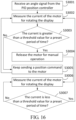
- FIG. 16 is a flowchart of a method for controlling the display 30 in an automatic control mode and in a manual control mode. The method may include the following steps.
- Step S 3001 Receive an angle signal from the PID position controller.
- the dual mode controller receives the angle signal from the PID position controller to rotate the display 30 by an angle of ⁇ 1 obj .
- Step S 3002 Measure the current of the motor 302 for rotating the display 30 .
- the current of the motor 302 When there is no external force applied on the display 30 , the current of the motor 302 will be less than a minimum threshold value. When the user applies an external force to the display 30 to manually rotate the display 30 , the current of the motor 302 will be greater than the maximum threshold value. By measuring and monitoring the current of the motor 302 , it can determine whether the user has applied an external force to the display 30 .
- Step S 3003 Determine whether the current is greater than a threshold value for a preset period of time.
- step S 3004 it is determined that the user has applied an external force to the display 30 if the current is greater than the maximum threshold value for 2 seconds. If so, the procedure goes to step S 3004 ; otherwise, the procedure goes to step S 3005 .
- Step S 3004 Release the motor 302 for manual operation.
- the processor 51 will release the motor 302 .
- the motor 302 can be disengaged from the display 30 , which frees the display 30 and allows the user to manually rotate the display 30 .
- Step S 3005 Keep sending a position command to the motor 302 .
- the processor 51 will keep sending a position command to the motor 302 such that the display 30 can rotate to the desired position according to the angle signal from the PID position controller.
- Step S 3006 Measure the current of the motor 302 for rotating the display 30 .
- the current of the motor 302 will he measured and monitored such that whether the external force is still applied on the display 30 can be determined.
- Step S 3007 Determine whether the current is less than a threshold value for a preset period of time.
- the procedure goes back to step S 3002 . If the current is not less than the minimum threshold value for a preset period of time, the procedure goes back to step S 3006 .
- the method shown in FIG. 16 allows the display 30 to be automatically rotated to a position where the camera 40 faces the face of the user, and allows the user to manually rotate the display 30 to a desired position. After the external force has ceased, the display 30 will be switched from the manual control mode to the automatic control mode. 1
- the robotic assistant 100 can be employed in assisted living facilities or healthcare facilities.
- the disclosure is not limited thereto.
- the robotic assistant 100 may be used in hospitals.
- the robotic assistant can promote an active living life style for the elderly people.
- the robotic assistant can allow them to do more exercise to maintain their mobility capability. Moving around also provide more chances for the elderly people to interact with other people (particularly in the elderly care facility or assistive living facility) so that they feel less isolated.
- the camera can be controlled to constantly face the face of the user, which allows the face of the user to be present in the center of the display.
- the robotic assistant can provide guidance/assistance by display information on the display, such as number of squats.
- the robotic assistant 100 may further include a foldable seat 90 rotatably coupled to the first housing 201 (which is also referred to as body 201 ), and an actuator 80 (see FIG. 21 ) that is configured to rotate the foldable seat 90 with respect to the body 201 .
- the seat 90 is rotatable between a folded position (see FIG. 17 ) and an unfolded position (see FIG. 18 ). The seat 90 in the unfolded position allows a user to sit thereon to have a rest.
- the processor 51 may analyze each command instruction and rotate the seat 90 to the folded or unfolded position.
- the processor 51 may receive a command instruction from a user (e.g., care seeker) to rotate the seat 90 to the unfolded position such that the user can sit on the seat 90 .
- the processor 51 may receive a command instruction from the user to rotate the seat 90 back to the folded position such that the robotic walking assistant 100 is ready to be pushed by the user.
- the processor 51 may rotate the seat 90 when certain conditions are met. For example, when the processor 51 determines that the user is tired according to the output from camera 71 , the processor 51 can rotate the seat 90 to the unfolded position such that the user can sit on the seat 90 .
- the processor 51 may receive a touch on a touch sensitive display, and a voice command via the microphone 83 and rotates the seat 90 accordingly.
- the seat 90 may include a hollow seat body 91 and the actuator 80 is arranged within the seat body 91 .
- the seat body 91 may include a seat base 921 and seat cover 922 that is connected to the seat base 921 .
- the actuator 80 is arranged in the space defined by the seat base 921 and seat cover 922 .
- the robotic walking assistant may include two support members 202 and 203 fixed to the wheeled base 10 .
- the wheeled base 10 may include an upper cover 101 and the two support members 202 and 203 are mounted on the upper cover 101 .
- the two support members 202 and 203 are substantially vertical and spaced apart from each other.
- the two support members 202 and 203 are received in the first housing 201 .
- the seat 90 is arranged between and rotatably connected to the support members 202 and 203 .
- the robotic walking assistant may include a first connecting shaft 93 that is connected the support member 202 .
- the actuator 80 includes a rotating output shaft 801 and the connecting shaft 93 is coaxially connected to the rotating output shaft 801 .
- the upper end of the support member 202 may define a through hole and the connecting shaft 93 passes through the through hole.
- the connecting shaft 93 may include a shank 931 and a head 932 that is formed at one end of the shank 931 and has a diameter greater than the diameter of the shank 931 .
- the head 932 abuts against the support member 202 and may be fixed to the support member 202 by fasteners, such as screws.
- the connecting shaft 93 is thus stationary with respect to the support member 202 .
- the connecting shaft 93 is substantially horizontal.
- the actuator 80 includes an actuator body 802 and the rotating output shaft 801 protrudes from a surface of the actuator body 802 .
- the actuator body 802 is fixed to the seat cover 922 . Since the connecting shaft 93 is stationary with respect to the support member 202 , and the connecting shaft 93 is coaxially connected to the rotating output shaft 801 , the seat 90 can rotate together with the actuator body 802 with respect to the connecting shaft 93 and the output shaft 801 when the actuator 80 is in operation.
- the actuator 80 may be fixed to the seat cover 922 through a first connecting member 941 and a second connecting member 942 .
- the first connecting member 941 may include a vertical tab 9411 defining a through hole and a horizontal tab 9412 fixed to the seat cover 922 .
- the connecting shaft 93 passes through the through hole in the upper end of the support member 202 , a through hole defined in the seat base 921 , and the through hole in the vertical tab 9411 .
- the second connecting member 942 may include a main body 9421 and a number of legs 9422 protruding from a first side of the main body 9421 .
- the legs 9422 are spaced apart form one another and fixed to the vertical tab 9411 .
- the actuator body 802 is fixed to the second side of the main body 9421 opposite the first side.
- the main body 9421 may define a through hole.
- the end of the rotating output shaft 801 passes through the through hole of the main body 9421 and is connected to the first connecting shaft 93 .
- the end of the rotating output shaft 801 may include a first disc 803
- the first connecting shaft 93 may include a second disc 933 at its end.
- the first disc 803 and the second disc 933 may be connected to each other by fasteners, such as screws.
- the first connecting shaft 93 is thus coaxially connected to the rotating output shaft 801 .
- the robotic walking assistant may include a second connecting shaft 95 that is connected the second support member 203 .
- the upper end of the support member 203 may define a through hole and the second connecting shaft 95 passes through the through hole.
- the second connecting shaft 95 may include a shank 951 and a head 952 that is formed at one end of the shank 951 and has a diameter greater than the diameter of the shank 951 .
- the head 952 abuts against the support member 203 and may be fixed to the support member 203 by fasteners, such as screws.
- the second connecting shaft 95 is thus stationary with respect to the support member 203 .
- the second connecting shaft 95 is substantially horizontal.
- the support the seat 90 is supported by and rotatable with respect to the second connecting shaft 95 .
- the seat 90 is rotatably connected to the second connecting shaft 95 through a third connecting member 943 .
- the third connecting member 943 may include a vertical tab 9431 defining a through hole and a horizontal tab 9432 fixed to the seat cover 922 .
- the connecting shaft 95 passes through the through hole in the upper end of the support member 203 , a through hole defined in the seat base 921 , and the through hole in the vertical tab 9431 .
- the second connecting shaft 95 and the first connecting shaft 93 extends along the same axis of rotation, about which the seat 90 rotates.
- the robotic walking assistant may further include a torsion spring 96 that is arranged around the second connecting shaft 9 S.
- the torsion spring 96 has two free ends that respectively abut against the foldable seat 90 and the second connecting shaft 95 .
- the torsion spring 90 is pre-loaded such that the extra spring force generated could counterweight the force (e.g., a pushing force from a user) exerted on the seat 90 when the seat 90 is folded.
- a spring holder 944 is fixed to the distal end of the second connecting shaft 95 , and the torsion spring 96 is arranged between the spring holder 944 and the vertical tab 9431 .
- One leg 961 of the torsion spring 96 abuts against the horizontal tab 9432 , and the other leg 962 is fit in a groove 9441 defined in the spring holder 944 , thereby holding the torsion spring 96 in place.
- the robotic walking assistant may further include an elastic member arranged between the third connecting member 943 and the second connecting shaft 95 .
- the third connecting member 943 may include a protruding portion 9433 protruding from the horizontal tab 9432 and extending away from the vertical tab 9431 .
- the elastic member is a spring-loaded pin 945 that is received in a hole defined in the spring holder 944 . The upper end of the elastic member abuts against the protruding portion 9433 . The elastic member applies a pushing force to the foldable seat 90 , thereby exerting torque to the foldable seat to compensate for gravity during rotation of the foldable seat 90 from the folded position to the unfolded position.
- the seat base 921 may define two chambers 9211 and 9212 .
- the actuator 80 , the first connecting member 941 , and the second connecting member 942 are received in the chamber 9211 , and the first connecting shaft 93 extends into the chamber 9211 to be connected to the rotating output shaft 801 .
- the third connecting member 943 , the spring holder 944 , the torsion spring 96 , and the elastic member 97 are received in the chamber 92112 , and the second connecting shaft 95 extends into the chamber 9212 .
- the seat base 921 may define a storage space 9213 in a lower side and include a door 9214 rotatably connected to the seat base 921 .
- the door 9214 is configured to keep the storage space 9213 closed.
- the storage space 9213 is to store objects, such as medicines, equipment, and food.
- the robotic walking assistant may further include a light sensor 78 arranged within the wheeled base 10 .
- the light sensor 78 may be arranged in a through hole defined in the wheeled base 10 .
- the light sensor 78 is electrically coupled to the control system 50 .
- the control system 50 may control the actuator 80 to rotate the foldable seat 90 to the unfolded position in response to the light sensor 78 detecting presence of a user for a preset time period. For example, after detecting the presence of a leg of the user in the field of view (FOV) of the light sensor 78 for three seconds, the control system 50 controls the actuator 80 to rotate the foldable seat 90 to the unfolded position.
- the light sensor 78 may be an infrared (IR) sensor. It should be noted that in other embodiments multiple IR sensors may be used so as to provide a large range of detection.
- a method for controlling the robotic walking assistant may include the following steps.
- Step S 251 Receive a command indicating rotation of the foldable seat.
- the control system 50 may receive the command from a user, and the command may be a touch input command, a voice command, and the like.
- the processor 51 may receive the command when certain conditions are met. For example, the processor 51 may receive the command after detecting the presence of a leg of the user in the field of view (FOV) of the light sensor 78 for three seconds.
- FOV field of view
- Step S 252 Send a position command to the actuator to rotate the foldable seat to a desired position based on the command indicating rotation of the foldable seat.
- the processor 51 may analyze the command indicating rotation of the foldable seat 90 and send a position command to the actuator 80 . For example, if the command indicates rotating the foldable seat 90 to the unfolded position, the processor 51 may send a position command to the actuator 80 to rotate foldable seat 90 to the unfolded position indicated by the command.
- the actuator 80 may be a servo motor, and the processor 51 may control the actuator 80 to operate in a position mode. In the position mode, processor 51 needs to keep sending position commands to the actuator 80 such that the actuator 80 can drive the foldable seat 90 to rotate to and remain in a desired position.
- the actuator 80 receives a position command, the output shaft of the actuator will rotate to the angular position corresponding to the position command and the actuator 80 will try to keep the output shaft in that angular position, even if an external force pushes against it.
- Step S 253 Detect whether an external force has applied to the foldable seat.
- the processor 51 may determine whether an external force has applied to the foldable seat 90 based on the current of the actuator 80 .
- the external force refers to a force from a user that exerts a torque to the foldable seat 90 .
- a user may push the foldable seat 90 in certain circumstances, thereby generating a torque to the foldable seat 90 .
- step S 253 may include the following steps.
- Step S 2531 Measure current of the actuator.
- Step S 2532 Determine that the external force has applied to the foldable seat in response to the current of the actuator being greater than a preset value for a preset time period.
- the torque generated due to the external force applied to the foldable seat 90 is proportional to the current of the actuator 80 .
- the processor 51 may monitor the current of the actuator 80 and determines that the external force has applied to the foldable seat when the current of the actuator 80 is greater than a preset value for a preset time period (e.g., 2 seconds). Otherwise, the processor 51 determines that no external force has applied to the foldable seat 90 .
- the procedure goes to step S 254 when an external force has applied to the foldable seat, and goes to step S 255 when no external force has applied to the foldable seat.
- Step S 254 Release the actuator to allow the foldable seat to be manually rotated in response to detection of the external force.
- the actuator 80 in the position mode will try to keep its output shaft in that angular position even if an external force pushes against it.
- the processor 51 may send a signal to release the actuator 80 from the position control to allow the output shaft to rotate due to the external force applied to the foldable seat 90 .
- a user can manually rotate the foldable seat 90 to a desired position.
- Step S 255 Send the position command to the actuator.
- the processor 51 When no external force has applied to the foldable seat, the processor 51 will send the position command to the actuator 80 so as to retain the foldable seat in the desired position. After that, the procedure goes back to step S 253 .
- the method may further include the steps as follows: Measure current of the actuator 80 ; determine a position of the foldable seat 90 ; and perform a compliant control to the foldable seat 90 to compensate for the external force in response to the foldable seat 90 being in the folded position or in the unfolded position.
- the compliant control enables the foldable seat 90 to react sally to the manual operation of a user.
- FIG. 26 shows an exemplary dynamic model of the foldable seat 90 .
- the position control for the dynamic model can be implemented by using a PD controller based on an equation as follows:
- I k p ( ⁇ l d - ⁇ l ) + k d ⁇ ⁇ ⁇ l k t ,
- I current of the actuator 80
- ⁇ ld represents a desired angular position of the foldable seat 90
- ⁇ l represents the current angular position of the foldable seat 90
- k p represents proportional gain
- k d represent derivative gain
- k t represents torque constant.
- the current angular position ⁇ t_0 of the foldable seat 90 is input into an admittance controller and the admittance controller outputs an angular position difference, thereby obtaining a new desired angular position ⁇ t_d , which is inputted into seat position control module.
- the seat position control module then generates a torque ⁇ m of the actuator 80 based on the new desired angular position ⁇ t_d , which is input into the dynamic model of the foldable seat 90 .
- the external force F ext from a user which can be estimated based on the measured current of the actuator 80 using the equation above in relation to the dynamic model, is input to the admittance controller.
- the dynamic model of the foldable seat 90 also outputs the actual angular position of the foldable seat 90 to the seat position control module.
- the method may further include the steps as shown in FIG. 28 .
- Step S 281 Measure current of the actuator 80 .
- Step S 282 Determine a position of the foldable seat 90 .
- the processor 51 may determine the position of the foldable seat 90 based on output from a rotary encoder that is mounted to the actuator 90 and provides feedback to the processor 51 by tracking the angular position of the output shaft of the actuator 90 . If the foldable seat 90 is in the folded or unfolded position, the procedure goes to step S 283 . Otherwise, the procedure goes back to step S 253 .
- Step S 283 The admittance controller outputs a new desired angular position ⁇ l_d the scat position control module base on the inputted current angular position ⁇ l_0 of the foldable seat 90 .
- the current angular position ⁇ l_0 is set to 10 degrees when the foldable seat 90 is in the unfolded position, and the current angular position ⁇ l_0 is set to 100 degrees when the foldable seat 90 is in the folded position.
- Step S 284 The seat position control module generates a torque ⁇ m of the actuator 80 and outputs the torque ⁇ m to the seat mechanism dynamics.
- Step S 285 The external force F ext from a user is input to the admittance controller.
- the direction effect of the external force is to increase the motor current, which will in turn generate a high torque, this new torque will be computed by the dynamic model.
- the admittance controller will compute and update fhe new “desired” angular position based on the external force and the dynamic model.
- a compliant control allows deviations from such reference position.
- the compliant control allows the foldable seat 90 to finally rotate to the desired position even after the external force does not act on the foldable seat 90 .
- the robotic walking assistant can measure the current of the actuator and adjust the torque of the actuator to compensate for the external force from a user when the actuator is released.
- the compliant control reflected in steps S 283 to S 285 is only an example, and may change according to actual needs.
- a mechanical damping system may be used for the compliant control.
Abstract
Description
where Px represent the x-coordinate of the key point P, Ax, Bx, Cx, and Dx represent the x-coordinates of the vertices A, B, C, and D, Py represent the y-coordinate of the key point P, Ay, By, Cy, and Dy represent the y-coordinates of the vertices A, B, C, and D. In one embodiment, it is determined that the face of the user is in the middle of the
where H represents the height of the image shown in
where ffocal_length represents the distance between the camera center and the image plane. According to the two equations, it can be obtained the following equation:
According to triangle similarity theorems,
Since
it can be otained the following equation:
AD and M0C are can be measured in advance, A0D0 are determined by counting the number of pixels between the potins A0 and D0, N1Q1 are determined by counting the number of pixels between the potins N1 and Q1. In this way, the pitch angle θ1 obj of the face of the user standing at the random, current location behind the
(see
r=Jlθl+βlθl+mgrcosθ1−ksθl−Fext l,
where r represents toque, θl represents angular position of the
where I represents current of the
Claims (18)
Priority Applications (2)
| Application Number | Priority Date | Filing Date | Title |
|---|---|---|---|
| US17/530,501 US11617705B2 (en) | 2021-09-07 | 2021-11-19 | Robotic assistant and method for controlling the same |
| CN202211422648.9A CN115816475A (en) | 2021-11-19 | 2022-11-14 | Robot assistant and control method thereof |
Applications Claiming Priority (2)
| Application Number | Priority Date | Filing Date | Title |
|---|---|---|---|
| US17/467,461 US11554071B2 (en) | 2020-12-07 | 2021-09-07 | Robotic assistant and method for controlling the same |
| US17/530,501 US11617705B2 (en) | 2021-09-07 | 2021-11-19 | Robotic assistant and method for controlling the same |
Related Parent Applications (1)
| Application Number | Title | Priority Date | Filing Date |
|---|---|---|---|
| US17/467,461 Continuation-In-Part US11554071B2 (en) | 2020-12-07 | 2021-09-07 | Robotic assistant and method for controlling the same |
Publications (2)
| Publication Number | Publication Date |
|---|---|
| US20230072318A1 US20230072318A1 (en) | 2023-03-09 |
| US11617705B2 true US11617705B2 (en) | 2023-04-04 |
Family
ID=85385476
Family Applications (1)
| Application Number | Title | Priority Date | Filing Date |
|---|---|---|---|
| US17/530,501 Active US11617705B2 (en) | 2021-09-07 | 2021-11-19 | Robotic assistant and method for controlling the same |
Country Status (1)
| Country | Link |
|---|---|
| US (1) | US11617705B2 (en) |
Families Citing this family (3)
| Publication number | Priority date | Publication date | Assignee | Title |
|---|---|---|---|---|
| WO2021086471A1 (en) * | 2019-10-28 | 2021-05-06 | Ambulatus Robotics LLC | Autonomous robotic mobile support system for the mobility-impaired |
| USD1014452S1 (en) * | 2021-04-05 | 2024-02-13 | Amazon Technologies, Inc. | Mobile electronic device |
| USD986119S1 (en) * | 2021-06-28 | 2023-05-16 | Ubtech North America Research And Development Center Corp | Robot |
Citations (5)
| Publication number | Priority date | Publication date | Assignee | Title |
|---|---|---|---|---|
| US5569129A (en) * | 1994-06-10 | 1996-10-29 | Mobility Research L.L.C. | Device for patient gait training |
| US20060031984A1 (en) * | 2003-03-04 | 2006-02-16 | Shigeo Takizawa | Motivative Exercise and Lifting Aid Dual Device |
| US20170001656A1 (en) * | 2015-07-02 | 2017-01-05 | RT. WORKS Co., Ltd. | Hand Cart |
| US20200281801A1 (en) * | 2012-08-17 | 2020-09-10 | Robert J. Karlovich | Mobility assistance device |
| US20220047440A1 (en) * | 2018-09-12 | 2022-02-17 | Asp Gmbh | Device for supporting the ability of a person with restricted mobility to move |
-
2021
- 2021-11-19 US US17/530,501 patent/US11617705B2/en active Active
Patent Citations (5)
| Publication number | Priority date | Publication date | Assignee | Title |
|---|---|---|---|---|
| US5569129A (en) * | 1994-06-10 | 1996-10-29 | Mobility Research L.L.C. | Device for patient gait training |
| US20060031984A1 (en) * | 2003-03-04 | 2006-02-16 | Shigeo Takizawa | Motivative Exercise and Lifting Aid Dual Device |
| US20200281801A1 (en) * | 2012-08-17 | 2020-09-10 | Robert J. Karlovich | Mobility assistance device |
| US20170001656A1 (en) * | 2015-07-02 | 2017-01-05 | RT. WORKS Co., Ltd. | Hand Cart |
| US20220047440A1 (en) * | 2018-09-12 | 2022-02-17 | Asp Gmbh | Device for supporting the ability of a person with restricted mobility to move |
Also Published As
| Publication number | Publication date |
|---|---|
| US20230072318A1 (en) | 2023-03-09 |
Similar Documents
| Publication | Publication Date | Title |
|---|---|---|
| US11617705B2 (en) | Robotic assistant and method for controlling the same | |
| Amirabdollahian et al. | Minimum jerk trajectory control for rehabilitation and haptic applications | |
| Hirata et al. | Motion control of intelligent passive-type walker for fall-prevention function based on estimation of user state | |
| US10265227B2 (en) | Mobile human-friendly assistive robot | |
| Grewal et al. | LIDAR-based autonomous wheelchair | |
| Ulrich et al. | The GuideCane-applying mobile robot technologies to assist the visually impaired | |
| US11554071B2 (en) | Robotic assistant and method for controlling the same | |
| US11806303B2 (en) | Robotic walking assistant | |
| US11918537B2 (en) | Robotic walking assistant, method for controlling the same and computer-readable storage medium | |
| Mou et al. | Context-aware assisted interactive robotic walker for parkinson's disease patients | |
| Devigne et al. | Low complex sensor-based shared control for power wheelchair navigation | |
| Yu et al. | An interactive robotic walker for assisting elderly mobility in senior care unit | |
| US10667980B2 (en) | Motorized robotic walker guided by an image processing system for human walking assistance | |
| Di et al. | Fall detection and prevention in the elderly based on the ZMP stability control | |
| Moreira et al. | Smart and assistive walker–asbgo: rehabilitation robotics: a smart–walker to assist ataxic patients | |
| Frizera et al. | The smart walkers as geriatric assistive device. the simbiosis purpose | |
| JP2023524550A (en) | robot assistant | |
| Scheidig et al. | May I keep an eye on your training? Gait assessment assisted by a mobile robot | |
| Fukuda et al. | Motion control and fall detection of intelligent cane robot | |
| TWI382833B (en) | Walking assistive system | |
| Trujillo-León et al. | Robotic cane controlled to adapt automatically to its user gait characteristics | |
| Yan et al. | Laser and force sensors based human motion intent estimation algorithm for walking-aid robot | |
| CN115816475A (en) | Robot assistant and control method thereof | |
| Hirota et al. | IMU sensor based human motion detection and its application to braking control of electric wheeled walker for fall-prevention | |
| Hirata et al. | Standing up and sitting down support using intelligent walker based on estimation of user states |
Legal Events
| Date | Code | Title | Description |
|---|---|---|---|
| AS | Assignment |
Owner name: UBTECH ROBOTICS CORP LTD, CHINA Free format text: ASSIGNMENT OF ASSIGNORS INTEREST;ASSIGNORS:DING, HOUZHU;OHANIAN, ARMEN GARDABAD;LAPLANTE, BRANDON JON;AND OTHERS;REEL/FRAME:058158/0508 Effective date: 20211116 Owner name: UBTECH NORTH AMERICA RESEARCH AND DEVELOPMENT CENTER CORP, CALIFORNIA Free format text: ASSIGNMENT OF ASSIGNORS INTEREST;ASSIGNORS:DING, HOUZHU;OHANIAN, ARMEN GARDABAD;LAPLANTE, BRANDON JON;AND OTHERS;REEL/FRAME:058158/0508 Effective date: 20211116 |
|
| FEPP | Fee payment procedure |
Free format text: ENTITY STATUS SET TO UNDISCOUNTED (ORIGINAL EVENT CODE: BIG.); ENTITY STATUS OF PATENT OWNER: LARGE ENTITY |
|
| AS | Assignment |
Owner name: UBKANG (QINGDAO) TECHNOLOGY CO., LTD., CHINA Free format text: ASSIGNMENT OF ASSIGNORS INTEREST;ASSIGNORS:UBTECH NORTH AMERICA RESEARCH AND DEVELOPMENT CENTER CORP;UBTECH ROBOTICS CORP LTD;REEL/FRAME:062319/0026 Effective date: 20230105 |
|
| STCF | Information on status: patent grant |
Free format text: PATENTED CASE |