US11601475B2 - Rating organization cybersecurity using active and passive external reconnaissance - Google Patents
Rating organization cybersecurity using active and passive external reconnaissance Download PDFInfo
- Publication number
- US11601475B2 US11601475B2 US17/162,683 US202117162683A US11601475B2 US 11601475 B2 US11601475 B2 US 11601475B2 US 202117162683 A US202117162683 A US 202117162683A US 11601475 B2 US11601475 B2 US 11601475B2
- Authority
- US
- United States
- Prior art keywords
- data
- cybersecurity
- reconnaissance
- information
- time
- Prior art date
- Legal status (The legal status is an assumption and is not a legal conclusion. Google has not performed a legal analysis and makes no representation as to the accuracy of the status listed.)
- Active, expires
Links
- 230000008520 organization Effects 0.000 title abstract description 19
- 238000000034 method Methods 0.000 claims description 83
- 230000009466 transformation Effects 0.000 claims description 37
- 230000015654 memory Effects 0.000 claims description 36
- 230000004044 response Effects 0.000 abstract description 21
- 238000010586 diagram Methods 0.000 description 49
- 230000000694 effects Effects 0.000 description 40
- 238000004458 analytical method Methods 0.000 description 37
- 230000008569 process Effects 0.000 description 33
- 230000006870 function Effects 0.000 description 21
- 230000006399 behavior Effects 0.000 description 16
- 238000004891 communication Methods 0.000 description 15
- 238000012545 processing Methods 0.000 description 15
- 238000005516 engineering process Methods 0.000 description 13
- 238000007726 management method Methods 0.000 description 13
- 230000000116 mitigating effect Effects 0.000 description 12
- 238000004088 simulation Methods 0.000 description 12
- 238000000844 transformation Methods 0.000 description 11
- 238000013500 data storage Methods 0.000 description 10
- 230000003542 behavioural effect Effects 0.000 description 8
- 238000004422 calculation algorithm Methods 0.000 description 8
- 239000000523 sample Substances 0.000 description 8
- 230000001010 compromised effect Effects 0.000 description 7
- 238000012986 modification Methods 0.000 description 7
- 230000004048 modification Effects 0.000 description 7
- 238000012544 monitoring process Methods 0.000 description 7
- 230000009471 action Effects 0.000 description 6
- 238000001514 detection method Methods 0.000 description 6
- 238000013459 approach Methods 0.000 description 5
- 238000010801 machine learning Methods 0.000 description 5
- 230000005291 magnetic effect Effects 0.000 description 5
- 238000012800 visualization Methods 0.000 description 5
- 230000002547 anomalous effect Effects 0.000 description 4
- 230000009193 crawling Effects 0.000 description 4
- 238000005259 measurement Methods 0.000 description 4
- 230000003287 optical effect Effects 0.000 description 4
- 238000013439 planning Methods 0.000 description 4
- 230000008859 change Effects 0.000 description 3
- 230000003116 impacting effect Effects 0.000 description 3
- 230000003993 interaction Effects 0.000 description 3
- 230000000670 limiting effect Effects 0.000 description 3
- 238000013507 mapping Methods 0.000 description 3
- 238000013515 script Methods 0.000 description 3
- 239000007787 solid Substances 0.000 description 3
- 238000012550 audit Methods 0.000 description 2
- 238000013475 authorization Methods 0.000 description 2
- 238000010923 batch production Methods 0.000 description 2
- 238000004364 calculation method Methods 0.000 description 2
- 238000013501 data transformation Methods 0.000 description 2
- 238000013461 design Methods 0.000 description 2
- 230000036541 health Effects 0.000 description 2
- 230000007774 longterm Effects 0.000 description 2
- 230000007246 mechanism Effects 0.000 description 2
- 230000035515 penetration Effects 0.000 description 2
- 230000002093 peripheral effect Effects 0.000 description 2
- 238000005067 remediation Methods 0.000 description 2
- 238000011160 research Methods 0.000 description 2
- 238000012502 risk assessment Methods 0.000 description 2
- 238000007790 scraping Methods 0.000 description 2
- 238000012360 testing method Methods 0.000 description 2
- 230000000007 visual effect Effects 0.000 description 2
- 241000239290 Araneae Species 0.000 description 1
- 241000283973 Oryctolagus cuniculus Species 0.000 description 1
- 235000009499 Vanilla fragrans Nutrition 0.000 description 1
- 244000263375 Vanilla tahitensis Species 0.000 description 1
- 235000012036 Vanilla tahitensis Nutrition 0.000 description 1
- 230000000454 anti-cipatory effect Effects 0.000 description 1
- 238000003491 array Methods 0.000 description 1
- 230000005540 biological transmission Effects 0.000 description 1
- 239000006227 byproduct Substances 0.000 description 1
- 230000001413 cellular effect Effects 0.000 description 1
- 238000004590 computer program Methods 0.000 description 1
- 230000001276 controlling effect Effects 0.000 description 1
- 230000002596 correlated effect Effects 0.000 description 1
- 238000007405 data analysis Methods 0.000 description 1
- 238000012517 data analytics Methods 0.000 description 1
- 238000013480 data collection Methods 0.000 description 1
- 238000013479 data entry Methods 0.000 description 1
- 238000013075 data extraction Methods 0.000 description 1
- 238000013499 data model Methods 0.000 description 1
- 230000007123 defense Effects 0.000 description 1
- 238000000605 extraction Methods 0.000 description 1
- 238000000556 factor analysis Methods 0.000 description 1
- 230000002349 favourable effect Effects 0.000 description 1
- 239000000835 fiber Substances 0.000 description 1
- 238000007689 inspection Methods 0.000 description 1
- 230000010354 integration Effects 0.000 description 1
- 230000001788 irregular Effects 0.000 description 1
- 230000037361 pathway Effects 0.000 description 1
- 230000002688 persistence Effects 0.000 description 1
- 230000002085 persistent effect Effects 0.000 description 1
- 230000003449 preventive effect Effects 0.000 description 1
- 230000002829 reductive effect Effects 0.000 description 1
- 230000001105 regulatory effect Effects 0.000 description 1
- 230000001846 repelling effect Effects 0.000 description 1
- 230000002441 reversible effect Effects 0.000 description 1
- 239000010979 ruby Substances 0.000 description 1
- 229910001750 ruby Inorganic materials 0.000 description 1
- 238000012358 sourcing Methods 0.000 description 1
- 238000012732 spatial analysis Methods 0.000 description 1
- 108020001568 subdomains Proteins 0.000 description 1
- 238000006467 substitution reaction Methods 0.000 description 1
- 230000026676 system process Effects 0.000 description 1
- 230000008685 targeting Effects 0.000 description 1
- 210000003813 thumb Anatomy 0.000 description 1
- 238000012876 topography Methods 0.000 description 1
- 238000012546 transfer Methods 0.000 description 1
- 238000011144 upstream manufacturing Methods 0.000 description 1
Images


Classifications
-
- H—ELECTRICITY
- H04—ELECTRIC COMMUNICATION TECHNIQUE
- H04L—TRANSMISSION OF DIGITAL INFORMATION, e.g. TELEGRAPHIC COMMUNICATION
- H04L63/00—Network architectures or network communication protocols for network security
- H04L63/20—Network architectures or network communication protocols for network security for managing network security; network security policies in general
-
- G—PHYSICS
- G06—COMPUTING; CALCULATING OR COUNTING
- G06F—ELECTRIC DIGITAL DATA PROCESSING
- G06F16/00—Information retrieval; Database structures therefor; File system structures therefor
- G06F16/20—Information retrieval; Database structures therefor; File system structures therefor of structured data, e.g. relational data
- G06F16/24—Querying
- G06F16/245—Query processing
- G06F16/2458—Special types of queries, e.g. statistical queries, fuzzy queries or distributed queries
- G06F16/2477—Temporal data queries
-
- G—PHYSICS
- G06—COMPUTING; CALCULATING OR COUNTING
- G06F—ELECTRIC DIGITAL DATA PROCESSING
- G06F16/00—Information retrieval; Database structures therefor; File system structures therefor
- G06F16/90—Details of database functions independent of the retrieved data types
- G06F16/95—Retrieval from the web
- G06F16/951—Indexing; Web crawling techniques
-
- H—ELECTRICITY
- H04—ELECTRIC COMMUNICATION TECHNIQUE
- H04L—TRANSMISSION OF DIGITAL INFORMATION, e.g. TELEGRAPHIC COMMUNICATION
- H04L63/00—Network architectures or network communication protocols for network security
- H04L63/14—Network architectures or network communication protocols for network security for detecting or protecting against malicious traffic
- H04L63/1408—Network architectures or network communication protocols for network security for detecting or protecting against malicious traffic by monitoring network traffic
- H04L63/1425—Traffic logging, e.g. anomaly detection
-
- H—ELECTRICITY
- H04—ELECTRIC COMMUNICATION TECHNIQUE
- H04L—TRANSMISSION OF DIGITAL INFORMATION, e.g. TELEGRAPHIC COMMUNICATION
- H04L63/00—Network architectures or network communication protocols for network security
- H04L63/14—Network architectures or network communication protocols for network security for detecting or protecting against malicious traffic
- H04L63/1441—Countermeasures against malicious traffic
Definitions
- the disclosure relates to the field of computer management, and more particularly to the field of cybersecurity and threat analytics.
- IPv4 address space consists of 2 32 , or almost 4.3 billion possible IP addresses, which is within the giga-order of magnitude.
- Today's computers have CPUs with gigahertz clock rates and gigabytes of RAM and storage.
- Today's networks allow band-widths exceeding 1 gigabit per second. This makes iterations over the entire IPv4 space possible within a comparatively short time period.
- Today's port scanning software is able to perform massive port scans up to the complete IPv4 space within minutes. Once a device is connected to the Internet, it will be almost immediately scanned for open ports and services. Most of these scans are done by anonymous individuals, in particular targeting at finding and exploiting system vulnerabilities. However, there is also a variety of individuals and organizations openly practicing massive port scanning and pursuing different objectives.
- What is needed is a system and method for performing active and passive external reconnaissance using network scanning, that feeds information into a distributed computational graph data pipeline to produce hybrid graph/time-series data for use in producing cybersecurity ratings for organizations.
- the inventor has developed a system and method for rating organization cybersecurity using active and passive external reconnaissance.
- the aspects described herein provide a system and methods for cybersecurity rating using active and passive external reconnaissance, comprising a web crawler that send message prompts to external hosts and receives responses from external hosts, a time-series data store that produces time-series data from the message responses, and a directed computational graph module that analyzes the time-series data to produce a weighted score representing the overall cybersecurity state of an organization.
- an advanced cyber decision platform for external network reconnaissance and cybersecurity rating comprising: a time-series data store comprising at least a processor, a memory, and a plurality of programming instructions stored in the memory and operating on the processor, wherein the programmable instructions, when operating on the processor, cause the processor to: receive a plurality of response messages from external hosts connected via a network; produce time-series data based on at least a portion of a received response message; a directed computational graph module comprising at least a processor, a memory, and a plurality of programming instructions stored in the memory and operating on the processor, wherein the programmable instructions, when operating on the processor, cause the processor to: perform a plurality of analysis and transformation operations on at least a portion of the time-series data; produce a weighted score based at least in part on the output of at least a portion of the analysis and transformation operations; a web crawler comprising at least a processor, a memory, and a plurality of programming instructions stored in the memory
- a method for external network reconnaissance and cybersecurity rating comprising the steps of: a) transmitting, using a web crawler, a plurality of message prompts to a plurality of external hosts via a network; b) receiving at least a message response from an external host; c) producing, using a time-series data store, time-series data based at least in part on at least a portion of the received message response; d) performing, using a directed computational graph module, a plurality of analysis and transformation operations on at least a portion of the time-series data; and e) producing a weighted score based at least in part on the output of at least a portion of the analysis and transformation operations, is disclosed.
- FIG. 1 is a block diagram of an exemplary system architecture for an advanced cyber decision platform for external network reconnaissance and cybersecurity rating.
- FIG. 2 A is a block diagram showing general steps for performing passive network reconnaissance.
- FIG. 2 B is a process diagram showing a general flow of a process for performing active reconnaissance using DNS leak information collection.
- FIG. 2 C is a process diagram showing a general flow of a process for performing active reconnaissance using web application and technology reconnaissance.
- FIG. 2 D is a process diagram showing a general flow of a process for producing a cybersecurity rating using reconnaissance data.
- FIG. 3 is a process diagram showing business operating system functions in use to mitigate cyberattacks.
- FIG. 4 is a process flow diagram of a method for segmenting cyberattack information to appropriate corporation parties.
- FIG. 5 is a diagram of an exemplary architecture for a system for rapid predictive analysis of very large data sets using an actor-driven distributed computational graph, according to one aspect.
- FIG. 6 is a diagram of an exemplary architecture for a system for rapid predictive analysis of very large data sets using an actor-driven distributed computational graph, according to one aspect.
- FIG. 7 is a diagram of an exemplary architecture for a system for rapid predictive analysis of very large data sets using an actor-driven distributed computational graph, according to one aspect.
- FIG. 8 is a flow diagram of an exemplary method for cybersecurity behavioral analytics, according to one aspect.
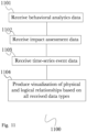
- FIG. 9 is a flow diagram of an exemplary method for measuring the effects of cybersecurity attacks, according to one aspect.
- FIG. 10 is a flow diagram of an exemplary method for continuous cybersecurity monitoring and exploration, according to one aspect.
- FIG. 11 is a flow diagram of an exemplary method for mapping a cyber-physical system graph, according to one aspect.
- FIG. 12 is a flow diagram of an exemplary method for continuous network resilience scoring, according to one aspect.
- FIG. 13 is a flow diagram of an exemplary method for cybersecurity privilege oversight, according to one aspect.
- FIG. 14 is a flow diagram of an exemplary method for cybersecurity risk management, according to one aspect.
- FIG. 15 is a flow diagram of an exemplary method for mitigating compromised credential threats, according to one aspect.
- FIG. 16 is a flow diagram of an exemplary method for dynamic network and rogue device discovery, according to one aspect.
- FIG. 17 is a flow diagram of an exemplary method for Kerberos “golden ticket” attack detection, according to one aspect.
- FIG. 18 is a flow diagram of an exemplary method for risk-based vulnerability and patch management, according to one aspect.
- FIG. 19 is a block diagram illustrating an exemplary hardware architecture of a computing device.
- FIG. 20 is a block diagram illustrating an exemplary logical architecture for a client device.
- FIG. 21 is a block diagram illustrating an exemplary architectural arrangement of clients, servers, and external services.
- FIG. 22 is another block diagram illustrating an exemplary hardware architecture of a computing device.
- the inventor has conceived, and reduced to practice, a system and method for rating organization cybersecurity using active and passive external reconnaissance.
- Devices that are in communication with each other need not be in continuous communication with each other, unless expressly specified otherwise.
- devices that are in communication with each other may communicate directly or indirectly through one or more communication means or intermediaries, logical or physical.
- steps may be performed simultaneously despite being described or implied as occurring non-simultaneously (e.g., because one step is described after the other step).
- the illustration of a process by its depiction in a drawing does not imply that the illustrated process is exclusive of other variations and modifications thereto, does not imply that the illustrated process or any of its steps are necessary to one or more of the aspects, and does not imply that the illustrated process is preferred.
- steps are generally described once per aspect, but this does not mean they must occur once, or that they may only occur once each time a process, method, or algorithm is carried out or executed. Some steps may be omitted in some aspects or some occurrences, or some steps may be executed more than once in a given aspect or occurrence.
- graph is a representation of information and relationships, where each primary unit of information makes up a “node” or “vertex” of the graph and the relationship between two nodes makes up an edge of the graph.
- Nodes can be further qualified by the connection of one or more descriptors or “properties” to that node. For example, given the node “James R,” name information for a person, qualifying properties might be “183 cm tall”, “DOB Aug. 13, 1965” and “speaks English”. Similar to the use of properties to further describe the information in a node, a relationship between two nodes that forms an edge can be qualified using a “label”.
- transformation graphs which are highly variable in size and node, edge composition as the system processes data streams.
- transformation graph may assume many shapes and sizes with a vast topography of edge relationships. The examples given were chosen for illustrative purposes only and represent a small number of the simplest of possibilities. These examples should not be taken to define the possible graphs expected as part of operation of the invention
- transformation is a function performed on zero or more streams of input data which results in a single stream of output which may or may not then be used as input for another transformation. Transformations may comprise any combination of machine, human or machine-human interactions Transformations need not change data that enters them, one example of this type of transformation would be a storage transformation which would receive input and then act as a queue for that data for subsequent transformations. As implied above, a specific transformation may generate output data in the absence of input data. A time stamp serves as a example. In the invention, transformations are placed into pipelines such that the output of one transformation may serve as an input for another. These pipelines can consist of two or more transformations with the number of transformations limited only by the resources of the system.
- transformation pipelines have been linear with each transformation in the pipeline receiving input from one antecedent and providing output to one subsequent with no branching or iteration.
- Other pipeline configurations are possible.
- the invention is designed to permit several of these configurations including, but not limited to: linear, afferent branch, efferent branch and cyclical.
- a “database” or “data storage subsystem” (these terms may be considered substantially synonymous), as used herein, is a system adapted for the long-term storage, indexing, and retrieval of data, the retrieval typically being via some sort of querying interface or language.
- “Database” may be used to refer to relational database management systems known in the art, but should not be considered to be limited to such systems.
- Many alternative database or data storage system technologies have been, and indeed are being, introduced in the art, including but not limited to distributed non-relational data storage systems such as Hadoop, column-oriented databases, in-memory databases, and the like.
- any data storage architecture may be used according to the aspects.
- one or more particular data storage needs are described as being satisfied by separate components (for example, an expanded private capital markets database and a configuration database), these descriptions refer to functional uses of data storage systems and do not refer to their physical architecture.
- any group of data storage systems of databases referred to herein may be included together in a single database management system operating on a single machine, or they may be included in a single database management system operating on a cluster of machines as is known in the art.
- any single database (such as an expanded private capital markets database) may be implemented on a single machine, on a set of machines using clustering technology, on several machines connected by one or more messaging systems known in the art, or in a master/slave arrangement common in the art.
- a “data context”, as used herein, refers to a set of arguments identifying the location of data. This could be a Rabbit queue, a .csv file in cloud-based storage, or any other such location reference except a single event or record. Activities may pass either events or data contexts to each other for processing. The nature of a pipeline allows for direct information passing between activities, and data locations or files do not need to be predetermined at pipeline start.
- Each batch activity may contain a “source” data context (this may be a streaming context if the upstream activities are streaming), and a “destination” data context (which is passed to the next activity).
- Streaming activities may have an optional “destination” streaming data context (optional meaning: caching/persistence of events vs. ephemeral), though this should not be part of the initial implementation.
- FIG. 1 is a block diagram of an advanced cyber decision platform for external network reconnaissance and cybersecurity rating.
- MDTSDB multidimensional time series database
- the directed computational graph module 155 retrieves one or more streams of data from a plurality of sources, which includes, but is in no way not limited to, a plurality of physical sensors, network service providers, web based questionnaires and surveys, monitoring of electronic infrastructure, crowd sourcing campaigns, and human input device information.
- data may be split into two identical streams in a specialized pre-programmed data pipeline 155 a , wherein one sub-stream may be sent for batch processing and storage while the other sub-stream may be reformatted for transformation pipeline analysis.
- the data is then transferred to the general transformer service module 160 for linear data transformation as part of analysis or the decomposable transformer service module 150 for branching or iterative transformations that are part of analysis.
- the directed computational graph module 155 represents all data as directed graphs where the transformations are nodes and the result messages between transformations edges of the graph.
- the high volume web crawling module 115 uses multiple server hosted preprogrammed web spiders, which while autonomously configured are deployed within a web scraping framework 115 a of which SCRAPYTM is an example, to identify and retrieve data of interest from web based sources that are not well tagged by conventional web crawling technology.
- the multiple dimension time series data store module 120 may receive streaming data from a large plurality of sensors that may be of several different types.
- the multiple dimension time series data store module may also store any time series data encountered by the system such as but not limited to enterprise network usage data, component and system logs, performance data, network service information captures such as, but not limited to news and financial feeds, and sales and service related customer data.
- the module is designed to accommodate irregular and high volume surges by dynamically allotting network bandwidth and server processing channels to process the incoming data.
- Inclusion of programming wrappers 120 a for languages examples of which are, but not limited to C++, PERL, PYTHON, and ERLANGTM allows sophisticated programming logic to be added to the default function of the multidimensional time series database 120 without intimate knowledge of the core programming, greatly extending breadth of function.
- Data retrieved by the multidimensional time series database (MDTSDB) 120 and the high volume web crawling module 115 may be further analyzed and transformed into task optimized results by the directed computational graph 155 and associated general transformer service 150 and decomposable transformer service 160 modules.
- data from the multidimensional time series database and high volume web crawling modules may be sent, often with scripted cuing information determining important vertexes 145 a , to the graph stack service module 145 which, employing standardized protocols for converting streams of information into graph representations of that data, for example, open graph internet technology although the invention is not reliant on any one standard.
- the graph stack service module 145 represents data in graphical form influenced by any pre-determined scripted modifications 145 a and stores it in a graph-based data store 145 b such as GIRAPHTM or a key value pair type data store REDISTM, or RIAKTM, among others, all of which are suitable for storing graph-based information.
- a graph-based data store 145 b such as GIRAPHTM or a key value pair type data store REDISTM, or RIAKTM, among others, all of which are suitable for storing graph-based information.
- Results of the transformative analysis process may then be combined with further client directives, additional business rules and practices relevant to the analysis and situational information external to the already available data in the automated planning service module 130 which also runs powerful information theory 130 a based predictive statistics functions and machine learning algorithms to allow future trends and outcomes to be rapidly forecast based upon the current system derived results and choosing each a plurality of possible business decisions.
- the automated planning service module 130 may propose business decisions most likely to result is the most favorable business outcome with a usably high level of certainty.
- the action outcome simulation module 125 with its discrete event simulator programming module 125 a coupled with the end user facing observation and state estimation service 140 which is highly scriptable 140 b as circumstances require and has a game engine 140 a to more realistically stage possible outcomes of business decisions under consideration, allows business decision makers to investigate the probable outcomes of choosing one pending course of action over another based upon analysis of the current available data.
- web crawler 115 may be used to perform a variety of port and service scanning operations on a plurality of hosts. This may be used to target individual network hosts (for example, to examine a specific server or client device) or to broadly scan any number of hosts (such as all hosts within a particular domain, or any number of hosts up to the complete IPv4 address space). Port scanning is primarily used for gathering information about hosts and services connected to a network, using probe messages sent to hosts that prompt a response from that host. Port scanning is generally centered around the transmission control protocol (TCP), and using the information provided in a prompted response a port scan can provide information about network and application layers on the targeted host.
- TCP transmission control protocol
- Port scan results can yield information on open, closed, or undetermined ports on a target host.
- An open port indicated that an application or service is accepting connections on this port (such as ports used for receiving customer web traffic on a web server), and these ports generally disclose the greatest quantity of useful information about the host.
- a closed port indicates that no application or service is listening for connections on that port, and still provides information about the host such as revealing the operating system of the host, which may discovered by fingerprinting the TCP/IP stack in a response. Different operating systems exhibit identifiable behaviors when populating TCP fields, and collecting multiple responses and matching the fields against a database of known fingerprints makes it possible to determine the OS of the host even when no ports are open.
- An undetermined port is one that does not produce a requested response, generally because the port is being filtered by a firewall on the host or between the host and the network (for example, a corporate firewall behind which all internal servers operate).
- Scanning may be defined by scope to limit the scan according to two dimensions, hosts and ports.
- a horizontal scan checks the same port on multiple hosts, often used by attackers to check for an open port on any available hosts to select a target for an attack that exploits a vulnerability using that port. This type of scan is also useful for security audits, to ensure that vulnerabilities are not exposed on any of the target hosts.
- a vertical scan defines multiple ports to examine on a single host, for example a “vanilla scan” which targets every port of a single host, or a “strobe scan” that targets a small subset of ports on the host. This type of scan is usually performed for vulnerability detection on single systems, and due to the single-host nature is impractical for large network scans.
- a block scan combines elements of both horizontal and vertical scanning, to scan multiple ports on multiple hosts. This type of scan is useful for a variety of service discovery and data collection tasks, as it allows a broad scan of many hosts (up to the entire Internet, using the complete IPv4 address space) for a number of desired ports in a single sweep.
- web crawler 115 may employ a variety of software suitable for the task, such as Nmap, ZMap, or masscan.
- Nmap is suitable for large scans as well as scanning individual hosts, and excels in offering a variety of diverse scanning techniques.
- ZMap is a newer application and unlike Nmap (which is more general-purpose), ZMap is designed specifically with Internet-wide scans as the intent. As a result, ZMap is far less customizable and relies on horizontal port scans for functionality, achieving fast scan times using techniques of probe randomization (randomizing the order in which probes are sent to hosts, minimizing network saturation) and asynchronous design (utilizing stateless operation to send and receive packets in separate processing threads).
- Masscan uses the same asynchronous operation model of ZMap, as well as probe randomization. In masscan however, a certain degree of statistical randomness is sacrificed to improve computation time for large scans (such as when scanning the entire IPv4 address space), using the BlackRock algorithm.
- This is a modified implementation of symmetric encryption algorithm DES, with fewer rounds and modulo operations in place of binary ones to allow for arbitrary ranges and achieve faster computation time for large data sets.
- Received scan responses may be collected and processed through a plurality of data pipelines 155 a to analyze the collected information.
- MDTSDB 120 and graph stack 145 may be used to produce a hybrid graph/time-series database using the analyzed data, forming a graph of Internet-accessible organization resources and their evolving state information over time.
- Customer-specific profiling and scanning information may be linked to CPG graphs (as described below in detail, referring to FIG. 11 ) for a particular customer, but this information may be further linked to the base-level graph of internet-accessible resources and information.
- techniques used may involve both passive, semi-passive and active scanning and reconnaissance.
- FIG. 2 A is a block diagram showing general steps 200 for performing passive network reconnaissance. It should be appreciated that the steps illustrated and described may be performed in any order, and that steps may be added or omitted as needed for any particular reconnaissance operation.
- a step 201 network address ranges and domains or sub-domains associated with a plurality of targets may be identified, for example to collect information for defining the scope of further scanning operations.
- external sites may be identified to understand relationships between targets and other third-party content providers, such as trust relationships or authoritative domain name service (DNS) resolution records.
- DNS domain name service
- individual people or groups may be identified using names, email addresses, phone numbers, or other identifying information that may be useful for a variety of social engineering activities.
- technologies used may be identified, such as types or versions of hardware or software used by an organization, and this may include collecting and extracting information from job descriptions (for example) to identify technologies in use by an organization (for example, a job description for an administrator familiar with specific database software indicates that said software is in use within the organization).
- content of interest may be identified, for example including web and email portals, log files, backup or archive files, and other forms of sensitive information that may be contained within HTML comments or client-side scripts, as may be useful for vulnerability discovery and penetration testing activities.
- publicly-available information may be used to identify vulnerabilities that may be exploited with further active penetration testing.
- FIG. 2 B is a process diagram showing a general flow of a process 210 for performing active reconnaissance using DNS leak information collection.
- publicly-available DNS leak disclosure information may be collected to maintain current information regarding known leaks and vulnerabilities.
- third-level domain (TLDR) information may be collected and used to report domain risk factors, such as domains that do not resolve properly (due to malformed DNS records, for example).
- TLDR third-level domain
- a DNS trust map may be created using a hybrid graph/time-series data structure, using a graph stack service 145 and MDTSDB 120 .
- This trust map may be produced as the output of an extraction process performed by a DCG 155 through a plurality of data pipelines 155 a , analyzing collected data and mapping data points to produce hybrid structured output representing each data point over time.
- the trust map may then be analyzed to identify anomalies, for example using community detection algorithms that may discover when new references are being created, and this may be used to identify vulnerabilities that may arise as a byproduct of the referential nature of a DNS hierarchy. In this manner, DCG pipeline processing and time-series data graphing may be used to identify vulnerabilities that would otherwise be obscured within a large dataset.
- FIG. 2 C is a process diagram showing a general flow of a process 220 for performing active reconnaissance using web application and technology reconnaissance.
- a plurality of manual HTTP requests may be transmitted to a host, for example to determine if a web server is announcing itself, or to obtain an application version number from an HTTP response message.
- a robots.txt used to identify and communicate with web crawlers and other automated “bots”, may be searched for to identify portions of an application or site that robots are requested to ignore.
- the host application layer may be fingerprinted, for example using file extensions and response message fields to identify characteristic patterns or markers that may be used to identify host or application details.
- a next step 224 publicly-exposed/admin pages may be checked, to determine if any administrative portals are exposed and therefore potentially-vulnerable, as well as to potentially determine administration policies or capabilities based on exposed information.
- an application may be profiled according to a particular toolset in use, such as WORDPRESSTM (for example) or other specific tools or plugins.
- FIG. 2 D is a process diagram showing a general flow of a process 230 for producing a cybersecurity rating using reconnaissance data.
- external reconnaissance may be performed using DNS and IP information as described above (referring to FIG. 2 B ), collecting information from DNS records, leak announcements, and publicly-available records to produce a DNS trust map from collected information and the DCG-driven analysis thereof.
- web and application recon may be performed (as described in FIG. 2 C ), collecting information on applications, sites, and publicly-available records.
- collected information over time may be analyzed for software version numbers, revealing the patching frequency of target hosts and their respective applications and services.
- timestamps may be associated with ongoing changes to reveal these updates over time.
- a plurality of additional endpoints may be scanned, such as (for example, including but not limited to) internet-of-things (IoT) devices that may be scanned and fingerprinted, end-user devices such as personal smartphones, tablets, or computers, or social network endpoints such as scraping content from user social media pages or feeds.
- IoT internet-of-things
- end-user devices such as personal smartphones, tablets, or computers
- social network endpoints such as scraping content from user social media pages or feeds.
- User devices may be fingerprinted and analyzed similar to organization hosts, and social media content may be retrieved such as collecting sentiment from services like TWITTERTM or LINKEDINTM, or analyzing job description listings and other publicly-available information.
- open-source intelligence feeds may be checked, such as company IP address blacklists, search domains, or information leaks (for example, posted to public records such as PASTEBINTM).
- collected information from all sources may be scored according to a weighted system, producing an overall cybersecurity rating score based on the information collected and the analysis of that information to reveal additional insights, relationships, and vulnerabilities.
- information from initial Internet recon operations may be assigned a score up to 400 points, along with up to 200 additional points for web/application recon results, 100 points for patch frequency, and 50 points each for additional endpoints and open-source intel results.
- this cybersecurity rating may evolve over time to continuously reflect the current state of the organization, reflecting any recent changes, newly-discovered or announced vulnerabilities, software or hardware updates, newly-added or removed devices or services, and any other changes that may occur.
- FIG. 3 is a process diagram showing a general flow 300 of business operating system functions in use to mitigate cyberattacks.
- Input network data which may include network flow patterns 321 , the origin and destination of each piece of measurable network traffic 322 , system logs from servers and workstations on the network 323 , endpoint data 323 a , any security event log data from servers or available security information and event (SIEM) systems 324 , external threat intelligence feeds 324 a , identity or assessment context 325 , external network health or cybersecurity feeds 326 , Kerberos domain controller or ACTIVE DIRECTORYTM server logs or instrumentation 327 and business unit performance related data 328 , among many other possible data types for which the invention was designed to analyze and integrate, may pass into 315 the business operating system 310 for analysis as part of its cyber security function.
- SIEM security information and event
- These multiple types of data from a plurality of sources may be transformed for analysis 311 , 312 using at least one of the specialized cybersecurity, risk assessment or common functions of the business operating system in the role of cybersecurity system, such as, but not limited to network and system user privilege oversight 331 , network and system user behavior analytics 332 , attacker and defender action timeline 333 , SIEM integration and analysis 334 , dynamic benchmarking 335 , and incident identification and resolution performance analytics 336 among other possible cybersecurity functions; value at risk (VAR) modeling and simulation 341 , anticipatory vs.
- VAR value at risk
- Output 317 can be used to configure network gateway security appliances 361 , to assist in preventing network intrusion through predictive change to infrastructure recommendations 362 , to alert an enterprise of ongoing cyberattack early in the attack cycle, possibly thwarting it but at least mitigating the damage 362 , to record compliance to standardized guidelines or SLA requirements 363 , to continuously probe existing network infrastructure and issue alerts to any changes which may make a breach more likely 364 , suggest solutions to any domain controller ticketing weaknesses detected 365 , detect presence of malware 366 , and perform one time or continuous vulnerability scanning depending on client directives 367 .
- These examples are, of course, only a subset of the possible uses of the system, they are exemplary in nature and do not reflect any boundaries in the capabilities of the invention.
- FIG. 4 is a process flow diagram of a method for segmenting cyberattack information to appropriate corporation parties 400 .
- one of the strengths of the advanced cyber-decision platform is the ability to finely customize reports and dashboards to specific audiences, concurrently is appropriate. This customization is possible due to the devotion of a portion of the business operating system's programming specifically to outcome presentation by modules which include the observation and state estimation service 140 with its game engine 140 a and script interpreter 140 b .
- issuance of specialized alerts, updates and reports may significantly assist in getting the correct mitigating actions done in the most timely fashion while keeping all participants informed at predesignated, appropriate granularity.
- Examples of groups that may receive specialized information streams include but may not be limited to front line responders during the attack 404 , incident forensics support both during and after the attack 405 , chief information security officer 406 and chief risk officer 407 the information sent to the latter two focused to appraise overall damage and to implement both mitigating strategy and preventive changes after the attack.
- Front line responders may use the cyber-decision platform's analyzed, transformed and correlated information specifically sent to them 404 a to probe the extent of the attack, isolate such things as: the predictive attacker's entry point onto the enterprise's network, the systems involved or the predictive ultimate targets of the attack and may use the simulation capabilities of the system to investigate alternate methods of successfully ending the attack and repelling the attackers in the most efficient manner, although many other queries known to those skilled in the art are also answerable by the invention. Simulations run may also include the predictive effects of any attack mitigating actions on normal and critical operation of the enterprise's IT systems and corporate users.
- a chief information security officer may use the cyber-decision platform to predictively analyze 406 a what corporate information has already been compromised, predictively simulate the ultimate information targets of the attack that may or may not have been compromised and the total impact of the attack what can be done now and in the near future to safeguard that information.
- the forensic responder may use the cyber-decision platform 405 a to clearly and completely map the extent of network infrastructure through predictive simulation and large volume data analysis.
- the forensic analyst may also use the platform's capabilities to perform a time series and infrastructural spatial analysis of the attack's progression with methods used to infiltrate the enterprise's subnets and servers.
- the chief risk officer would perform analyses of what information 407 a was stolen and predictive simulations on what the theft means to the enterprise as time progresses. Additionally, the system's predictive capabilities may be employed to assist in creation of a plan for changes of the IT infrastructural that should be made that are optimal for remediation of cybersecurity risk under possibly limited enterprise budgetary constraints in place at the company so as to maximize financial outcome.
- FIG. 5 is a diagram of an exemplary architecture for a system for rapid predictive analysis of very large data sets using an actor-driven distributed computational graph 500 , according to one aspect.
- a DCG 500 may comprise a pipeline orchestrator 501 that may be used to perform a variety of data transformation functions on data within a processing pipeline, and may be used with a messaging system 510 that enables communication with any number of various services and protocols, relaying messages and translating them as needed into protocol-specific API system calls for interoperability with external systems (rather than requiring a particular protocol or service to be integrated into a DCG 500 ).
- Pipeline orchestrator 501 may spawn a plurality of child pipeline clusters 502 a - b , which may be used as dedicated workers for streamlining parallel processing. In some arrangements, an entire data processing pipeline may be passed to a child cluster 502 a for handling, rather than individual processing tasks, enabling each child cluster 502 a - b to handle an entire data pipeline in a dedicated fashion to maintain isolated processing of different pipelines using different cluster nodes 502 a - b .
- Pipeline orchestrator 501 may provide a software API for starting, stopping, submitting, or saving pipelines. When a pipeline is started, pipeline orchestrator 501 may send the pipeline information to an available worker node 502 a - b , for example using AKKATM clustering.
- a reporting object with status information may be maintained.
- Streaming activities may report the last time an event was processed, and the number of events processed.
- Batch activities may report status messages as they occur.
- Pipeline orchestrator 501 may perform batch caching using, for example, an IGFSTM caching filesystem. This allows activities 512 a - d within a pipeline 502 a - b to pass data contexts to one another, with any necessary parameter configurations.
- a pipeline manager 511 a - b may be spawned for every new running pipeline, and may be used to send activity, status, lifecycle, and event count information to the pipeline orchestrator 501 .
- a plurality of activity actors 512 a - d may be created by a pipeline manager 511 a - b to handle individual tasks, and provide output to data services 522 a - d .
- Data models used in a given pipeline may be determined by the specific pipeline and activities, as directed by a pipeline manager 511 a - b .
- Each pipeline manager 511 a - b controls and directs the operation of any activity actors 512 a - d spawned by it.
- a pipeline process may need to coordinate streaming data between tasks.
- a pipeline manager 511 a - b may spawn service connectors to dynamically create TCP connections between activity instances 512 a - d .
- Data contexts may be maintained for each individual activity 512 a - d , and may be cached for provision to other activities 512 a - d as needed.
- a data context defines how an activity accesses information, and an activity 512 a - d may process data or simply forward it to a next step. Forwarding data between pipeline steps may route data through a streaming context or batch context.
- a client service cluster 530 may operate a plurality of service actors 521 a - d to serve the requests of activity actors 512 a - d , ideally maintaining enough service actors 521 a - d to support each activity per the service type. These may also be arranged within service clusters 520 a - d , in a manner similar to the logical organization of activity actors 512 a - d within clusters 502 a - b in a data pipeline.
- a logging service 530 may be used to log and sample DCG requests and messages during operation while notification service 540 may be used to receive alerts and other notifications during operation (for example to alert on errors, which may then be diagnosed by reviewing records from logging service 530 ), and by being connected externally to messaging system 510 , logging and notification services can be added, removed, or modified during operation without impacting DCG 500 .
- a plurality of DCG protocols 550 a - b may be used to provide structured messaging between a DCG 500 and messaging system 510 , or to enable messaging system 510 to distribute DCG messages across service clusters 520 a - d as shown.
- a service protocol 560 may be used to define service interactions so that a DCG 500 may be modified without impacting service implementations. In this manner it can be appreciated that the overall structure of a system using an actor-driven DCG 500 operates in a modular fashion, enabling modification and substitution of various components without impacting other operations or requiring additional reconfiguration.
- FIG. 6 is a diagram of an exemplary architecture for a system for rapid predictive analysis of very large data sets using an actor-driven distributed computational graph 500 , according to one aspect.
- a variant messaging arrangement may utilize messaging system 510 as a messaging broker using a streaming protocol 610 , transmitting and receiving messages immediately using messaging system 510 as a message broker to bridge communication between service actors 521 a - b as needed.
- individual services 522 a - b may communicate directly in a batch context 620 , using a data context service 630 as a broker to batch-process and relay messages between services 522 a - b.
- FIG. 7 is a diagram of an exemplary architecture for a system for rapid predictive analysis of very large data sets using an actor-driven distributed computational graph 500 , according to one aspect.
- a variant messaging arrangement may utilize a service connector 710 as a central message broker between a plurality of service actors 521 a - b , bridging messages in a streaming context 610 while a data context service 630 continues to provide direct peer-to-peer messaging between individual services 522 a - b in a batch context 620 .
- FIG. 8 is a flow diagram of an exemplary method 800 for cybersecurity behavioral analytics, according to one aspect.
- behavior analytics may utilize passive information feeds from a plurality of existing endpoints (for example, including but not limited to user activity on a network, network performance, or device behavior) to generate security solutions.
- a web crawler 115 may passively collect activity information, which may then be processed 802 using a DCG 155 to analyze behavior patterns.
- anomalous behavior may be recognized 803 (for example, based on a threshold of variance from an established pattern or trend) such as high-risk users or malicious software operators such as bots.
- anomalous behaviors may then be used 804 to analyze potential angles of attack and then produce 805 security suggestions based on this second-level analysis and predictions generated by an action outcome simulation module 125 to determine the likely effects of the change.
- the suggested behaviors may then be automatically implemented 806 as needed.
- Passive monitoring 801 then continues, collecting information after new security solutions are implemented 806 , enabling machine learning to improve operation over time as the relationship between security changes and observed behaviors and threats are observed and analyzed.
- This method 800 for behavioral analytics enables proactive and high-speed reactive defense capabilities against a variety of cyberattack threats, including anomalous human behaviors as well as nonhuman “bad actors” such as automated software bots that may probe for, and then exploit, existing vulnerabilities.
- Using automated behavioral learning in this manner provides a much more responsive solution than manual intervention, enabling rapid response to threats to mitigate any potential impact.
- Utilizing machine learning behavior further enhances this approach, providing additional proactive behavior that is not possible in simple automated approaches that merely react to threats as they occur.
- FIG. 9 is a flow diagram of an exemplary method 900 for measuring the effects of cybersecurity attacks, according to one aspect.
- impact assessment of an attack may be measured using a DCG 155 to analyze a user account and identify its access capabilities 901 (for example, what files, directories, devices or domains an account may have access to). This may then be used to generate 902 an impact assessment score for the account, representing the potential risk should that account be compromised.
- the impact assessment score for any compromised accounts may be used to produce a “blast radius” calculation 903 , identifying exactly what resources are at risk as a result of the intrusion and where security personnel should focus their attention.
- simulated intrusions may be run 904 to identify potential blast radius calculations for a variety of attacks and to determine 905 high risk accounts or resources so that security may be improved in those key areas rather than focusing on reactive solutions.
- FIG. 10 is a flow diagram of an exemplary method 1000 for continuous cybersecurity monitoring and exploration, according to one aspect.
- a state observation service 140 may receive data from a variety of connected systems 1001 such as (for example, including but not limited to) servers, domains, databases, or user directories. This information may be received continuously, passively collecting events and monitoring activity over time while feeding 1002 collected information into a graphing service 145 for use in producing time-series graphs 1003 of states and changes over time. This collated time-series data may then be used to produce a visualization 1004 of changes over time, quantifying collected data into a meaningful and understandable format.
- connected systems 1001 such as (for example, including but not limited to) servers, domains, databases, or user directories.
- This information may be received continuously, passively collecting events and monitoring activity over time while feeding 1002 collected information into a graphing service 145 for use in producing time-series graphs 1003 of states and changes over time.
- This collated time-series data may then be used to produce
- FIG. 11 is a flow diagram of an exemplary method 50966 for mapping a cyber-physical system graph (CPG), according to one aspect.
- a cyber-physical system graph may comprise a visualization of hierarchies and relationships between devices and resources in a security infrastructure, contextualizing security information with physical device relationships that are easily understandable for security personnel and users.
- behavior analytics information (as described previously, referring to FIG. 8 ) may be received at a graphing service 145 for inclusion in a CPG.
- impact assessment scores (as described previously, referring to FIG. 9 ) may be received and incorporated in the CPG information, adding risk assessment context to the behavior information.
- time-series information (as described previously, referring to FIG. 10 ) may be received and incorporated, updating CPG information as changes occur and events are logged.
- This information may then be used to produce 1104 a graph visualization of users, servers, devices, and other resources correlating physical relationships (such as a user's personal computer or smartphone, or physical connections between servers) with logical relationships (such as access privileges or database connections), to produce a meaningful and contextualized visualization of a security infrastructure that reflects the current state of the internal relationships present in the infrastructure.
- FIG. 12 is a flow diagram of an exemplary method 1200 for continuous network resilience scoring, according to one aspect.
- a baseline score can be used to measure an overall level of risk for a network infrastructure, and may be compiled by first collecting 1201 information on publicly-disclosed vulnerabilities, such as (for example) using the Internet or common vulnerabilities and exploits (CVE) process. This information may then 1202 be incorporated into a CPG as described previously in FIG. 11 , and the combined data of the CPG and the known vulnerabilities may then be analyzed 1203 to identify the relationships between known vulnerabilities and risks exposed by components of the infrastructure. This produces a combined CPG 1204 that incorporates both the internal risk level of network resources, user accounts, and devices as well as the actual risk level based on the analysis of known vulnerabilities and security risks.
- CVE common vulnerabilities and exploits
- FIG. 13 is a flow diagram of an exemplary method 1300 for cybersecurity privilege oversight, according to one aspect.
- time-series data (as described above, referring to FIG. 10 ) may be collected 1301 for user accounts, credentials, directories, and other user-based privilege and access information.
- This data may then 1302 be analyzed to identify changes over time that may affect security, such as modifying user access privileges or adding new users.
- the results of analysis may be checked 1303 against a CPG (as described previously in FIG. 11 ), to compare and correlate user directory changes with the actual infrastructure state.
- CPG as described previously in FIG. 11
- This comparison may be used to perform accurate and context-enhanced user directory audits 1304 that identify not only current user credentials and other user-specific information, but changes to this information over time and how the user information relates to the actual infrastructure (for example, credentials that grant access to devices and may therefore implicitly grant additional access due to device relationships that were not immediately apparent from the user directory alone).
- FIG. 14 is a flow diagram of an exemplary method 1400 for cybersecurity risk management, according to one aspect.
- multiple methods described previously may be combined to provide live assessment of attacks as they occur, by first receiving 1401 time-series data for an infrastructure (as described previously, in FIG. 10 ) to provide live monitoring of network events.
- This data is then enhanced 1402 with a CPG (as described above in FIG. 11 ) to correlate events with actual infrastructure elements, such as servers or accounts.
- an event for example, an attempted attack against a vulnerable system or resource
- the event is logged in the time-series data 1404 , and compared against the CPG 1405 to determine the impact.
- This is enhanced with the inclusion of impact assessment information 1406 for any affected resources, and the attack is then checked against a baseline score 1407 to determine the full extent of the impact of the attack and any necessary modifications to the infrastructure or policies.
- FIG. 15 is a flow diagram of an exemplary method 1500 for mitigating compromised credential threats, according to one aspect.
- impact assessment scores (as described previously, referring to FIG. 9 ) may be collected 1501 for user accounts in a directory, so that the potential impact of any given credential attack is known in advance of an actual attack event.
- This information may be combined with a CPG 1502 as described previously in FIG. 11 , to contextualize impact assessment scores within the infrastructure (for example, so that it may be predicted what systems or resources might be at risk for any given credential attack).
- a simulated attack may then be performed 1503 to use machine learning to improve security without waiting for actual attacks to trigger a reactive response.
- a blast radius assessment (as described above in FIG. 9 ) may be used in response 1504 to determine the effects of the simulated attack and identify points of weakness, and produce a recommendation report 1505 for improving and hardening the infrastructure against future attacks.
- FIG. 16 is a flow diagram of an exemplary method 1600 for dynamic network and rogue device discovery, according to one aspect.
- an advanced cyber decision platform may continuously monitor a network in real-time 1601 , detecting any changes as they occur.
- a CPG may be updated 1603 with the new connection information, which may then be compared against the network's resiliency score 1604 to examine for potential risk.
- the blast radius metric for any other devices involved in the connection may also be checked 1605 , to examine the context of the connection for risk potential (for example, an unknown connection to an internal data server with sensitive information may be considered a much higher risk than an unknown connection to an externally-facing web server). If the connection is a risk, an alert may be sent to an administrator 1606 with the contextual information for the connection to provide a concise notification of relevant details for quick handling.
- FIG. 17 is a flow diagram of an exemplary method 1700 for Kerberos “golden ticket” attack detection, according to one aspect.
- Kerberos is a network authentication protocol employed across many enterprise networks to enable single sign-on and authentication for enterprise services. This makes it an attractive target for attacks, which can result in persistent, undetected access to services within a network in what is known as a “golden ticket” attack.
- behavioral analytics may be employed to detect forged authentication tickets resulting from an attack.
- an advanced cyber decision platform may continuously monitor a network 1701 , informing a CPG in real-time of all traffic associated with people, places, devices, or services 1702 .
- Machine learning algorithms detect behavioral anomalies as they occur in real-time 1703 , notifying administrators with an assessment of the anomalous event 1704 as well as a blast radius score for the particular event and a network resiliency score to advise of the overall health of the network. By automatically detecting unusual behavior and informing an administrator of the anomaly along with contextual information for the event and network, a compromised ticket is immediately detected when a new authentication connection is made.
- FIG. 18 is a flow diagram of an exemplary method 1800 for risk-based vulnerability and patch management, according to one aspect.
- an advanced cyber decision platform may monitor all information about a network 1801 , including (but not limited to) device telemetry data, log files, connections and network events, deployed software versions, or contextual user activity information. This information is incorporated into a CPG 1802 to maintain an up-to-date model of the network in real-time.
- a blast radius score may be assessed 1803 and the network's resiliency score may be updated 1804 as needed.
- a security alert may then be produced 1805 to notify an administrator of the vulnerability and its impact, and a proposed patch may be presented 1806 along with the predicted effects of the patch on the vulnerability's blast radius and the overall network resiliency score. This determines both the total impact risk of any particular vulnerability, as well as the overall effect of each vulnerability on the network as a whole.
- This continuous network assessment may be used to collect information about new vulnerabilities and exploits to provide proactive solutions with clear result predictions, before attacks occur.
- the techniques disclosed herein may be implemented on hardware or a combination of software and hardware. For example, they may be implemented in an operating system kernel, in a separate user process, in a library package bound into network applications, on a specially constructed machine, on an application-specific integrated circuit (ASIC), or on a network interface card.
- ASIC application-specific integrated circuit
- Software/hardware hybrid implementations of at least some of the aspects disclosed herein may be implemented on a programmable network-resident machine (which should be understood to include intermittently connected network-aware machines) selectively activated or reconfigured by a computer program stored in memory.
- a programmable network-resident machine which should be understood to include intermittently connected network-aware machines
- Such network devices may have multiple network interfaces that may be configured or designed to utilize different types of network communication protocols.
- a general architecture for some of these machines may be described herein in order to illustrate one or more exemplary means by which a given unit of functionality may be implemented.
- At least some of the features or functionalities of the various aspects disclosed herein may be implemented on one or more general-purpose computers associated with one or more networks, such as for example an end-user computer system, a client computer, a network server or other server system, a mobile computing device (e.g., tablet computing device, mobile phone, smartphone, laptop, or other appropriate computing device), a consumer electronic device, a music player, or any other suitable electronic device, router, switch, or other suitable device, or any combination thereof.
- at least some of the features or functionalities of the various aspects disclosed herein may be implemented in one or more virtualized computing environments (e.g., network computing clouds, virtual machines hosted on one or more physical computing machines, or other appropriate virtual environments).
- Computing device 10 may be, for example, any one of the computing machines listed in the previous paragraph, or indeed any other electronic device capable of executing software- or hardware-based instructions according to one or more programs stored in memory.
- Computing device 10 may be configured to communicate with a plurality of other computing devices, such as clients or servers, over communications networks such as a wide area network a metropolitan area network, a local area network, a wireless network, the Internet, or any other network, using known protocols for such communication, whether wireless or wired.
- communications networks such as a wide area network a metropolitan area network, a local area network, a wireless network, the Internet, or any other network, using known protocols for such communication, whether wireless or wired.
- computing device 10 includes one or more central processing units (CPU) 12 , one or more interfaces 15 , and one or more busses 14 (such as a peripheral component interconnect (PCI) bus).
- CPU 12 may be responsible for implementing specific functions associated with the functions of a specifically configured computing device or machine.
- a computing device 10 may be configured or designed to function as a server system utilizing CPU 12 , local memory 11 and/or remote memory 16 , and interface(s) 15 .
- CPU 12 may be caused to perform one or more of the different types of functions and/or operations under the control of software modules or components, which for example, may include an operating system and any appropriate applications software, drivers, and the like.
- CPU 12 may include one or more processors 13 such as, for example, a processor from one of the Intel, ARM, Qualcomm, and AMD families of microprocessors.
- processors 13 may include specially designed hardware such as application-specific integrated circuits (ASICs), electrically erasable programmable read-only memories (EEPROMs), field-programmable gate arrays (FPGAs), and so forth, for controlling operations of computing device 10 .
- ASICs application-specific integrated circuits
- EEPROMs electrically erasable programmable read-only memories
- FPGAs field-programmable gate arrays
- a local memory 11 such as non-volatile random access memory (RAM) and/or read-only memory (ROM), including for example one or more levels of cached memory
- RAM non-volatile random access memory
- ROM read-only memory
- Memory 11 may be used for a variety of purposes such as, for example, caching and/or storing data, programming instructions, and the like. It should be further appreciated that CPU 12 may be one of a variety of system-on-a-chip (SOC) type hardware that may include additional hardware such as memory or graphics processing chips, such as a QUALCOMM SNAPDRAGONTM or SAMSUNG EXYNOSTM CPU as are becoming increasingly common in the art, such as for use in mobile devices or integrated devices.
- SOC system-on-a-chip
- processor is not limited merely to those integrated circuits referred to in the art as a processor, a mobile processor, or a microprocessor, but broadly refers to a microcontroller, a microcomputer, a programmable logic controller, an application-specific integrated circuit, and any other programmable circuit.
- interfaces 15 are provided as network interface cards (NICs).
- NICs control the sending and receiving of data packets over a computer network; other types of interfaces 15 may for example support other peripherals used with computing device 10 .
- the interfaces that may be provided are Ethernet interfaces, frame relay interfaces, cable interfaces, DSL interfaces, token ring interfaces, graphics interfaces, and the like.
- interfaces may be provided such as, for example, universal serial bus (USB), Serial, Ethernet, FIREWIRETM, THUNDERBOLTTM, PCI, parallel, radio frequency (RF), BLUETOOTHTM, near-field communications (e.g., using near-field magnetics), 802.11 (WiFi), frame relay, TCP/IP, ISDN, fast Ethernet interfaces, Gigabit Ethernet interfaces, Serial ATA (SATA) or external SATA (ESATA) interfaces, high-definition multimedia interface (HDMI), digital visual interface (DVI), analog or digital audio interfaces, asynchronous transfer mode (ATM) interfaces, high-speed serial interface (HSSI) interfaces, Point of Sale (POS) interfaces, fiber data distributed interfaces (FDDIs), and the like.
- USB universal serial bus
- RF radio frequency
- BLUETOOTHTM near-field communications
- near-field communications e.g., using near-field magnetics
- WiFi wireless FIREWIRETM
- Such interfaces 15 may include physical ports appropriate for communication with appropriate media. In some cases, they may also include an independent processor (such as a dedicated audio or video processor, as is common in the art for high-fidelity AN hardware interfaces) and, in some instances, volatile and/or non-volatile memory (e.g., RAM).
- an independent processor such as a dedicated audio or video processor, as is common in the art for high-fidelity AN hardware interfaces
- volatile and/or non-volatile memory e.g., RAM
- FIG. 19 illustrates one specific architecture for a computing device 10 for implementing one or more of the aspects described herein, it is by no means the only device architecture on which at least a portion of the features and techniques described herein may be implemented.
- architectures having one or any number of processors 13 may be used, and such processors 13 may be present in a single device or distributed among any number of devices.
- a single processor 13 handles communications as well as routing computations, while in other aspects a separate dedicated communications processor may be provided.
- different types of features or functionalities may be implemented in a system according to the aspect that includes a client device (such as a tablet device or smartphone running client software) and server systems (such as a server system described in more detail below).
- the system of an aspect may employ one or more memories or memory modules (such as, for example, remote memory block 16 and local memory 11 ) configured to store data, program instructions for the general-purpose network operations, or other information relating to the functionality of the aspects described herein (or any combinations of the above).
- Program instructions may control execution of or comprise an operating system and/or one or more applications, for example.
- Memory 16 or memories 11 , 16 may also be configured to store data structures, configuration data, encryption data, historical system operations information, or any other specific or generic non-program information described herein.
- At least some network device aspects may include nontransitory machine-readable storage media, which, for example, may be configured or designed to store program instructions, state information, and the like for performing various operations described herein.
- nontransitory machine-readable storage media include, but are not limited to, magnetic media such as hard disks, floppy disks, and magnetic tape; optical media such as CD-ROM disks; magneto-optical media such as optical disks, and hardware devices that are specially configured to store and perform program instructions, such as read-only memory devices (ROM), flash memory (as is common in mobile devices and integrated systems), solid state drives (SSD) and “hybrid SSD” storage drives that may combine physical components of solid state and hard disk drives in a single hardware device (as are becoming increasingly common in the art with regard to personal computers), memristor memory, random access memory (RAM), and the like.
- ROM read-only memory
- flash memory as is common in mobile devices and integrated systems
- SSD solid state drives
- hybrid SSD hybrid SSD
- such storage means may be integral and non-removable (such as RAM hardware modules that may be soldered onto a motherboard or otherwise integrated into an electronic device), or they may be removable such as swappable flash memory modules (such as “thumb drives” or other removable media designed for rapidly exchanging physical storage devices), “hot-swappable” hard disk drives or solid state drives, removable optical storage discs, or other such removable media, and that such integral and removable storage media may be utilized interchangeably.
- swappable flash memory modules such as “thumb drives” or other removable media designed for rapidly exchanging physical storage devices
- hot-swappable hard disk drives or solid state drives
- removable optical storage discs or other such removable media
- program instructions include both object code, such as may be produced by a compiler, machine code, such as may be produced by an assembler or a linker, byte code, such as may be generated by for example a JAVATM compiler and may be executed using a Java virtual machine or equivalent, or files containing higher level code that may be executed by the computer using an interpreter (for example, scripts written in Python, Perl, Ruby, Groovy, or any other scripting language).
- interpreter for example, scripts written in Python, Perl, Ruby, Groovy, or any other scripting language.
- FIG. 20 there is shown a block diagram depicting a typical exemplary architecture of one or more aspects or components thereof on a standalone computing system.
- Computing device 20 includes processors 21 that may run software that carry out one or more functions or applications of aspects, such as for example a client application 24 .
- Processors 21 may carry out computing instructions under control of an operating system 22 such as, for example, a version of MICROSOFT WINDOWSTM operating system, APPLE macOSTM or iOSTM operating systems, some variety of the Linux operating system, ANDROIDTM operating system, or the like.
- an operating system 22 such as, for example, a version of MICROSOFT WINDOWSTM operating system, APPLE macOSTM or iOSTM operating systems, some variety of the Linux operating system, ANDROIDTM operating system, or the like.
- one or more shared services 23 may be operable in system 20 , and may be useful for providing common services to client applications 24 .
- Services 23 may for example be WINDOWSTM services, user-space common services in a Linux environment, or any other type of common service architecture used with operating system 21 .
- Input devices 28 may be of any type suitable for receiving user input, including for example a keyboard, touchscreen, microphone (for example, for voice input), mouse, touchpad, trackball, or any combination thereof.
- Output devices 27 may be of any type suitable for providing output to one or more users, whether remote or local to system 20 , and may include for example one or more screens for visual output, speakers, printers, or any combination thereof.
- Memory 25 may be random-access memory having any structure and architecture known in the art, for use by processors 21 , for example to run software.
- Storage devices 26 may be any magnetic, optical, mechanical, memristor, or electrical storage device for storage of data in digital form (such as those described above, referring to FIG. 19 ). Examples of storage devices 26 include flash memory, magnetic hard drive, CD-ROM, and/or the like.
- systems may be implemented on a distributed computing network, such as one having any number of clients and/or servers.
- FIG. 21 there is shown a block diagram depicting an exemplary architecture 30 for implementing at least a portion of a system according to one aspect on a distributed computing network.
- any number of clients 33 may be provided.
- Each client 33 may run software for implementing client-side portions of a system; clients may comprise a system 20 such as that illustrated in FIG. 20 .
- any number of servers 32 may be provided for handling requests received from one or more clients 33 .
- Clients 33 and servers 32 may communicate with one another via one or more electronic networks 31 , which may be in various aspects any of the Internet, a wide area network, a mobile telephony network (such as CDMA or GSM cellular networks), a wireless network (such as WiFi, WiMAX, LTE, and so forth), or a local area network (or indeed any network topology known in the art; the aspect does not prefer any one network topology over any other).
- Networks 31 may be implemented using any known network protocols, including for example wired and/or wireless protocols.
- servers 32 may call external services 37 when needed to obtain additional information, or to refer to additional data concerning a particular call. Communications with external services 37 may take place, for example, via one or more networks 31 .
- external services 37 may comprise web-enabled services or functionality related to or installed on the hardware device itself. For example, in one aspect where client applications 24 are implemented on a smartphone or other electronic device, client applications 24 may obtain information stored in a server system 32 in the cloud or on an external service 37 deployed on one or more of a particular enterprise's or user's premises.
- clients 33 or servers 32 may make use of one or more specialized services or appliances that may be deployed locally or remotely across one or more networks 31 .
- one or more databases 34 may be used or referred to by one or more aspects. It should be understood by one having ordinary skill in the art that databases 34 may be arranged in a wide variety of architectures and using a wide variety of data access and manipulation means.
- one or more databases 34 may comprise a relational database system using a structured query language (SQL), while others may comprise an alternative data storage technology such as those referred to in the art as “NoSQL” (for example, HADOOP CASSANDRATM, GOOGLE BIGTABLETM, and so forth).
- SQL structured query language
- variant database architectures such as column-oriented databases, in-memory databases, clustered databases, distributed databases, or even flat file data repositories may be used according to the aspect. It will be appreciated by one having ordinary skill in the art that any combination of known or future database technologies may be used as appropriate, unless a specific database technology or a specific arrangement of components is specified for a particular aspect described herein. Moreover, it should be appreciated that the term “database” as used herein may refer to a physical database machine, a cluster of machines acting as a single database system, or a logical database within an overall database management system.
- security and configuration management are common information technology (IT) and web functions, and some amount of each are generally associated with any IT or web systems. It should be understood by one having ordinary skill in the art that any configuration or security subsystems known in the art now or in the future may be used in conjunction with aspects without limitation, unless a specific security 36 or configuration system 35 or approach is specifically required by the description of any specific aspect.
- IT information technology
- FIG. 22 shows an exemplary overview of a computer system 40 as may be used in any of the various locations throughout the system. It is exemplary of any computer that may execute code to process data. Various modifications and changes may be made to computer system 40 without departing from the broader scope of the system and method disclosed herein.
- Central processor unit (CPU) 41 is connected to bus 42 , to which bus is also connected memory 43 , nonvolatile memory 44 , display 47 , input/output (I/O) unit 48 , and network interface card (NIC) 53 .
- I/O unit 48 may, typically, be connected to keyboard 49 , pointing device 50 , hard disk 52 , and real-time clock 51 .
- NIC 53 connects to network 54 , which may be the Internet or a local network, which local network may or may not have connections to the Internet. Also shown as part of system 40 is power supply unit 45 connected, in this example, to a main alternating current (AC) supply 46 . Not shown are batteries that could be present, and many other devices and modifications that are well known but are not applicable to the specific novel functions of the current system and method disclosed herein.
- AC alternating current
- functionality for implementing systems or methods of various aspects may be distributed among any number of client and/or server components.
- various software modules may be implemented for performing various functions in connection with the system of any particular aspect, and such modules may be variously implemented to run on server and/or client components.
Abstract
Description
| Application | ||
| No. | Date Filed | Title |
| Current | Herewith | RATING ORGANIZATION |
| application | CYBERSECURITY USING | |
| ACTIVE AND PASSIVE | ||
| EXTERNAL RECONNAISSANCE | ||
| Is a continuation of: | ||
| 16/720.383 | Dec. 19, | RATING ORGANIZATION |
| 2019 | CYBERSECURITY USING | |
| ACTIVE AND PASSIVE | ||
| EXTERNAL RECONNAISSANCE | ||
| Which is a continuation of: | ||
| 15/823,363 | Nov. 27, | RATING ORGANIZATION |
| Pat. | 2017 | CYBERSECURITY USING |
| 10,560,483 | Issue Date | ACTIVE AND PASSIVE |
| Feb. 11, | EXTERNAL RECONNAISSANCE | |
| 2020 | Which is a continuation-in-part of: | |
| 15/725,274 | Oct. 4, | APPLICATION OF ADVANCED |
| Pat. | 2017 | CYBERSECURITY THREAT |
| 10,609,079 | Issue Date | MITIGATION TO ROGUE |
| Mar 31, | DEVICES, PRIVILEGE | |
| 2020 | ESCALATION, AND RISK- | |
| BASED VULNERABILITY | ||
| AND PATCH MANAGEMENT | ||
| Which is a continuation-in-part of: | ||
| 15/655,113 | Jul. 20, | ADVANCED CYBERSECURITY |
| Pat. | 2017 | THREAT MITIGATION USING |
| 10,735,456 | Issue Date | BEHAVIORAL AND DEEP |
| Aug. 4, | ANALYTICS | |
| 2020 | Which is a continuation-in-part of: | |
| 15/616,427 | Jun. 7, | RAPID PREDICTIVE ANALYSIS |
| 2017 | OF VERY LARGE DATA SETS | |
| USING AN ACTOR-DRIVEN | ||
| DISTRIBUTED COMPUTATIONAL | ||
| GRAPH | ||
| Which is a continuation-in-part of: | ||
| 14/925,974 | Oct. 28, | RAPID PREDICTIVE ANALYSIS |
| 2015 | OF VERY LARGE DATA SETS | |
| USING THE DISTRIBUTED | ||
| COMPUTATIONAL GRAPH | ||
| Current | Herewith | RATING ORGANIZATION |
| application | CYBERSECURITY USING | |
| ACTIVE AND PASSIVE | ||
| EXTERNAL RECONNAISSANCE | ||
| Is a continuation of: | ||
| 16/720,383 | Dec. 19, | RATING ORGANIZATION |
| 2019 | CYBERSECURITY USING | |
| ACTIVE AND PASSIVE | ||
| EXTERNAL RECONNAISSANCE | ||
| Which is a continuation of: | ||
| 15/823,363 | Nov. 27, | RATING ORGANIZATION |
| Pat. | 2017 | CYBERSECURITY USING |
| 10,560,483 | Issue Date | ACTIVE AND PASSIVE |
| Feb 11, | EXTERNAL RECONNAISSANCE | |
| 2020 | Which is a continuation-in-part of: | |
| 15/725,274 | Oct. 4, | APPLICATION OF ADVANCED |
| Pat. | 2017 | CYBERSECURITY THREAT |
| 10,609,079 | Issue Date | MITIGATION TO ROGUE |
| Mar. 31, | DEVICES, PRIVILEGE | |
| 2020 | ESCALATION, AND RISK- | |
| BASED VULNERABILITY | ||
| AND PATCH MANAGEMENT | ||
| Which is a continuation-in-part of: | ||
| 15/655,113 | Jul. 20, | ADVANCED CYBERSECURITY |
| Pat. | 2017 | THREAT MITIGATION USING |
| 10,735,456 | Issue Date | BEHAVIORAL AND DEEP |
| Aug. 4, | ANALYTICS | |
| 2020 | Which is a continuation-in-part of: | |
| 15/237,625 | Aug. 15, | DETECTION MITIGATION |
| Patent: | 2016 | AND REMEDIATION OF |
| 10,248,910 | Issue | CYBERATTACKS EMPLOYING |
| Date: | AN ADVANCED CYBER- | |
| Apr. 2, | DECISION PLATFORM | |
| 2019 | Which is a continuation-in-part of: | |
| 15/206,195 | Jul. 8, | ACCURATE AND DETAILED |
| 2016 | MODELING OF SYSTEMS | |
| WITH LARGE COMPLEX | ||
| DATASETS USING A | ||
| DISTRIBUTED SIMULATION | ||
| ENGINE | ||
| Which is a continuation-in-part of: | ||
| 15/186,453 | Jun. 18, | SYSTEM FOR AUTOMATED |
| 2016 | CAPTURE AND ANALYSIS | |
| OF BUSINESS INFORMATION | ||
| FOR RELIABLE BUSINESS | ||
| VENTURE OUTCOME | ||
| PREDICTION | ||
| Which is a continuation-in-part of: | ||
| 15/166,158 | May 26, | SYSTEM FOR AUTOMATED |
| 2016 | CAPTURE AND ANALYSIS OF | |
| BUSINESS INFORMATION FOR | ||
| SECURITY AND CLIENT- | ||
| FACING INFRASTRUCTURE | ||
| RELIABILITY | ||
| Which is a continuation-in-part of: | ||
| 15/141,752 | Apr. 28, | SYSTEM FOR FULLY |
| Pat. | 2016 | INTEGRATED CAPTURE, AND |
| 10,860,962 | Issue Date | ANALYSIS OF BUSINESS |
| Dec. 8, | INFORMATION RESULTING | |
| 2020 | IN PREDICTIVE DECISION | |
| MAKING AND SIMULATION | ||
| Which is a continuation-in-part of: | ||
| 15/091,563 | Apr. 5, | SYSTEM FOR CAPTURE, |
| Patent: | 2016 | ANALYSIS AND STORAGE OF |
| 10,204,147 | Issue | TIME SERIES DATA FROM |
| Date: | SENSORS WITH | |
| Feb. 12, | HETEROGENEOUS REPORT | |
| 2019 | INTERVAL PROFILES | |
| And is a continuation-in-part of: | ||
| 14/986,536 | Dec. 31, | DISTRIBUTED SYSTEM FOR |
| Patent: | 2015 | LARGE VOLUME DEEP WEB |
| 10,210,255 | Issue | DATA EXTRACTION |
| Date: | And is a continuation-in-part of: | |
| Feb. 19, | ||
| 2019 | ||
| 14/925,974 | Oct. 28, | RAPID PREDICTIVE ANALYSIS |
| 2015 | OF VERY LARGE DATA SETS | |
| USING THE DISTRIBUTED | ||
| COMPUTATIONAL GRAPH | ||
| the entire specification of each of which is incorporated herein by reference. | ||
Claims (2)
Priority Applications (3)
| Application Number | Priority Date | Filing Date | Title |
|---|---|---|---|
| US17/162,683 US11601475B2 (en) | 2015-10-28 | 2021-01-29 | Rating organization cybersecurity using active and passive external reconnaissance |
| US18/171,328 US20230283641A1 (en) | 2015-10-28 | 2023-02-18 | Dynamic cybersecurity scoring using traffic fingerprinting and risk score improvement |
| US18/339,214 US20230362200A1 (en) | 2015-10-28 | 2023-06-21 | Dynamic cybersecurity scoring and operational risk reduction assessment |
Applications Claiming Priority (14)
| Application Number | Priority Date | Filing Date | Title |
|---|---|---|---|
| US14/925,974 US20170124464A1 (en) | 2015-10-28 | 2015-10-28 | Rapid predictive analysis of very large data sets using the distributed computational graph |
| US14/986,536 US10210255B2 (en) | 2015-12-31 | 2015-12-31 | Distributed system for large volume deep web data extraction |
| US15/091,563 US10204147B2 (en) | 2016-04-05 | 2016-04-05 | System for capture, analysis and storage of time series data from sensors with heterogeneous report interval profiles |
| US15/141,752 US10860962B2 (en) | 2015-10-28 | 2016-04-28 | System for fully integrated capture, and analysis of business information resulting in predictive decision making and simulation |
| US15/166,158 US20170124501A1 (en) | 2015-10-28 | 2016-05-26 | System for automated capture and analysis of business information for security and client-facing infrastructure reliability |
| US15/186,453 US20170124497A1 (en) | 2015-10-28 | 2016-06-18 | System for automated capture and analysis of business information for reliable business venture outcome prediction |
| US15/206,195 US20170124492A1 (en) | 2015-10-28 | 2016-07-08 | System for automated capture and analysis of business information for reliable business venture outcome prediction |
| US15/237,625 US10248910B2 (en) | 2015-10-28 | 2016-08-15 | Detection mitigation and remediation of cyberattacks employing an advanced cyber-decision platform |
| US15/616,427 US20170371726A1 (en) | 2015-10-28 | 2017-06-07 | Rapid predictive analysis of very large data sets using an actor-driven distributed computational graph |
| US15/655,113 US10735456B2 (en) | 2015-10-28 | 2017-07-20 | Advanced cybersecurity threat mitigation using behavioral and deep analytics |
| US15/725,274 US10609079B2 (en) | 2015-10-28 | 2017-10-04 | Application of advanced cybersecurity threat mitigation to rogue devices, privilege escalation, and risk-based vulnerability and patch management |
| US15/823,363 US10560483B2 (en) | 2015-10-28 | 2017-11-27 | Rating organization cybersecurity using active and passive external reconnaissance |
| US16/720,383 US10944795B2 (en) | 2015-10-28 | 2019-12-19 | Rating organization cybersecurity using active and passive external reconnaissance |
| US17/162,683 US11601475B2 (en) | 2015-10-28 | 2021-01-29 | Rating organization cybersecurity using active and passive external reconnaissance |
Related Parent Applications (1)
| Application Number | Title | Priority Date | Filing Date |
|---|---|---|---|
| US16/720,383 Continuation US10944795B2 (en) | 2015-10-28 | 2019-12-19 | Rating organization cybersecurity using active and passive external reconnaissance |
Related Child Applications (1)
| Application Number | Title | Priority Date | Filing Date |
|---|---|---|---|
| US18/171,328 Continuation-In-Part US20230283641A1 (en) | 2015-10-28 | 2023-02-18 | Dynamic cybersecurity scoring using traffic fingerprinting and risk score improvement |
Publications (2)
| Publication Number | Publication Date |
|---|---|
| US20210297452A1 US20210297452A1 (en) | 2021-09-23 |
| US11601475B2 true US11601475B2 (en) | 2023-03-07 |
Family
ID=62980920
Family Applications (3)
| Application Number | Title | Priority Date | Filing Date |
|---|---|---|---|
| US15/823,363 Active 2035-10-29 US10560483B2 (en) | 2015-10-28 | 2017-11-27 | Rating organization cybersecurity using active and passive external reconnaissance |
| US16/720,383 Active US10944795B2 (en) | 2015-10-28 | 2019-12-19 | Rating organization cybersecurity using active and passive external reconnaissance |
| US17/162,683 Active 2036-05-31 US11601475B2 (en) | 2015-10-28 | 2021-01-29 | Rating organization cybersecurity using active and passive external reconnaissance |
Family Applications Before (2)
| Application Number | Title | Priority Date | Filing Date |
|---|---|---|---|
| US15/823,363 Active 2035-10-29 US10560483B2 (en) | 2015-10-28 | 2017-11-27 | Rating organization cybersecurity using active and passive external reconnaissance |
| US16/720,383 Active US10944795B2 (en) | 2015-10-28 | 2019-12-19 | Rating organization cybersecurity using active and passive external reconnaissance |
Country Status (1)
| Country | Link |
|---|---|
| US (3) | US10560483B2 (en) |
Families Citing this family (18)
| Publication number | Priority date | Publication date | Assignee | Title |
|---|---|---|---|---|
| US10560483B2 (en) * | 2015-10-28 | 2020-02-11 | Qomplx, Inc. | Rating organization cybersecurity using active and passive external reconnaissance |
| US10812519B2 (en) * | 2016-12-29 | 2020-10-20 | Bce Inc. | Cyber threat intelligence threat and vulnerability assessment of service supplier chain |
| US10565373B1 (en) * | 2017-02-21 | 2020-02-18 | Ca, Inc. | Behavioral analysis of scripting utility usage in an enterprise |
| US10791138B1 (en) * | 2017-03-30 | 2020-09-29 | Fireeye, Inc. | Subscription-based malware detection |
| CN109413050B (en) * | 2018-10-05 | 2020-11-24 | 国网湖南省电力有限公司 | Access rate self-adaptive internet vulnerability information acquisition method and system |
| US11283824B1 (en) * | 2019-02-05 | 2022-03-22 | Cytellix Corporation | Real-time cybersecurity status system with event ticker |
| US11271961B1 (en) | 2019-04-09 | 2022-03-08 | Cytellix Corporation | Cloud-based cybersecurity management of hierarchical network groups |
| US11861692B2 (en) * | 2019-06-04 | 2024-01-02 | Sap Se | Automated hybrid pipeline for customer identification |
| US11757907B1 (en) | 2019-06-18 | 2023-09-12 | Cytellix Corporation | Cybersecurity threat intelligence and remediation system |
| US11588857B2 (en) * | 2019-10-04 | 2023-02-21 | Palo Alto Networks, Inc. | Network asset lifecycle management |
| US11916949B2 (en) * | 2019-11-19 | 2024-02-27 | National Technology & Engineering Solutions Of Sandia, Llc | Internet of things and operational technology detection and visualization platform |
| US11704363B2 (en) * | 2019-12-17 | 2023-07-18 | Paypal, Inc. | System and method for generating highly scalable temporal graph database |
| WO2021243321A1 (en) * | 2020-05-29 | 2021-12-02 | Qomplx, Inc. | A system and methods for score cybersecurity |
| US11586167B2 (en) | 2020-11-11 | 2023-02-21 | Mapped Inc. | Automatic discovery of relationships among equipment through observation over time |
| US20220159029A1 (en) * | 2020-11-13 | 2022-05-19 | Cyberark Software Ltd. | Detection of security risks based on secretless connection data |
| US20220239693A1 (en) * | 2021-01-22 | 2022-07-28 | Comcast Cable Communications, Llc | Systems and methods for improved domain name system security |
| US11372937B1 (en) * | 2021-07-08 | 2022-06-28 | metacluster lt, UAB | Throttling client requests for web scraping |
| WO2023215892A1 (en) | 2022-05-06 | 2023-11-09 | Mapped Inc. | Ensemble learning for extracting semantics of data in building systems |
Citations (35)
| Publication number | Priority date | Publication date | Assignee | Title |
|---|---|---|---|---|
| US6976053B1 (en) * | 1999-10-14 | 2005-12-13 | Arcessa, Inc. | Method for using agents to create a computer index corresponding to the contents of networked computers |
| US20080010683A1 (en) | 2006-07-10 | 2008-01-10 | Baddour Victor L | System and method for analyzing web content |
| US20080126408A1 (en) * | 2006-06-23 | 2008-05-29 | Invensys Systems, Inc. | Presenting continuous timestamped time-series data values for observed supervisory control and manufacturing/production parameters |
| US20080133540A1 (en) * | 2006-12-01 | 2008-06-05 | Websense, Inc. | System and method of analyzing web addresses |
| US7660815B1 (en) | 2006-06-30 | 2010-02-09 | Amazon Technologies, Inc. | Method and system for occurrence frequency-based scaling of navigation path weights among online content sources |
| US7774335B1 (en) | 2005-08-23 | 2010-08-10 | Amazon Technologies, Inc. | Method and system for determining interest levels of online content navigation paths |
| US20100281539A1 (en) * | 2009-04-29 | 2010-11-04 | Juniper Networks, Inc. | Detecting malicious network software agents |
| US20110313956A1 (en) * | 2010-06-16 | 2011-12-22 | Sony Corporation | Information processing apparatus, information processing method and program |
| US20120197911A1 (en) * | 2011-01-28 | 2012-08-02 | Cisco Technology, Inc. | Searching Sensor Data |
| US8281121B2 (en) * | 2010-05-13 | 2012-10-02 | Microsoft Corporation | Private aggregation of distributed time-series data |
| US8386519B2 (en) | 2008-12-30 | 2013-02-26 | Expanse Networks, Inc. | Pangenetic web item recommendation system |
| US20130103657A1 (en) * | 2010-05-14 | 2013-04-25 | Hitachi, Ltd. | Time-series data management device, system, method, and program |
| US20130212638A1 (en) | 2012-02-09 | 2013-08-15 | Aol Inc. | Systems and methods for testing online systems and content |
| US20130304623A1 (en) | 2012-04-18 | 2013-11-14 | The Florida State University Research Foundation, Inc. | Stock ranking & price prediction based on neighborhood model |
| US20140074850A1 (en) | 2012-09-07 | 2014-03-13 | Splunk Inc. | Visualization of data from clusters |
| US20140082730A1 (en) * | 2012-09-18 | 2014-03-20 | Kddi Corporation | System and method for correlating historical attacks with diverse indicators to generate indicator profiles for detecting and predicting future network attacks |
| US20140101763A1 (en) * | 2012-10-09 | 2014-04-10 | Tracevector, Inc. | Systems and methods for capturing or replaying time-series data |
| US8793758B2 (en) | 2009-01-28 | 2014-07-29 | Headwater Partners I Llc | Security, fraud detection, and fraud mitigation in device-assisted services systems |
| US8806361B1 (en) | 2013-09-16 | 2014-08-12 | Splunk Inc. | Multi-lane time-synched visualizations of machine data events |
| US8826426B1 (en) | 2011-05-05 | 2014-09-02 | Symantec Corporation | Systems and methods for generating reputation-based ratings for uniform resource locators |
| US20150020199A1 (en) * | 2012-03-22 | 2015-01-15 | Los Alamos National Security, Llc | Path scanning for the detection of anomalous subgraphs and use of dns requests and host agents for anomaly/change detection and network situational awareness |
| US20150033341A1 (en) | 2013-07-24 | 2015-01-29 | Webroot Inc. | System and method to detect threats to computer based devices and systems |
| US9031870B2 (en) | 2008-12-30 | 2015-05-12 | Expanse Bioinformatics, Inc. | Pangenetic web user behavior prediction system |
| US20150180891A1 (en) * | 2013-12-19 | 2015-06-25 | Splunk Inc. | Using network locations obtained from multiple threat lists to evaluate network data or machine data |
| US20150215332A1 (en) | 2013-01-30 | 2015-07-30 | Skyhigh Networks, Inc. | Cloud service usage risk assessment using darknet intelligence |
| US20150213631A1 (en) * | 2014-01-27 | 2015-07-30 | Splunk Inc. | Time-based visualization of the number of events having various values for a field |
| US20150295775A1 (en) * | 2014-04-15 | 2015-10-15 | Splunk Inc. | Graphical configuration of event streams for network data capture and processing |
| US20150295766A1 (en) * | 2014-04-15 | 2015-10-15 | Splunk Inc. | Transformation of network data at remote capture agents |
| US20150347523A1 (en) | 2012-05-15 | 2015-12-03 | Splunk Inc. | Managing data searches using generation identifiers |
| US20150363840A1 (en) * | 2014-06-13 | 2015-12-17 | Mastercard International Incorporated | Systems and Methods for Recommending Merchants to Consumers |
| US20160127262A1 (en) * | 2014-10-31 | 2016-05-05 | The Nielsen Company (Us), Llc | Method and apparatus to throttle media access by web crawlers |
| US20160140519A1 (en) | 2013-06-04 | 2016-05-19 | Sebastjan Trepca | Aggregating system |
| US20160162543A1 (en) | 2014-12-05 | 2016-06-09 | General Electric Company | Searching for and finding data across industrial time series data |
| US20160306806A1 (en) * | 2014-10-03 | 2016-10-20 | Palantir Technologies Inc. | Data aggregation and analysis system |
| US20210297452A1 (en) * | 2015-10-28 | 2021-09-23 | Qomplx, Inc. | Rating organization cybersecurity using active and passive external reconnaissance |
Family Cites Families (8)
| Publication number | Priority date | Publication date | Assignee | Title |
|---|---|---|---|---|
| DE19632609A1 (en) | 1996-08-13 | 1998-02-19 | Duerr Systems Gmbh | Manufacturing plant |
| US9916133B2 (en) | 2013-03-14 | 2018-03-13 | Microsoft Technology Licensing, Llc | Software release workflow management |
| US9602530B2 (en) | 2014-03-28 | 2017-03-21 | Zitovault, Inc. | System and method for predicting impending cyber security events using multi channel behavioral analysis in a distributed computing environment |
| US20160275123A1 (en) | 2015-03-18 | 2016-09-22 | Hitachi, Ltd. | Pipeline execution of multiple map-reduce jobs |
| US20170124464A1 (en) | 2015-10-28 | 2017-05-04 | Fractal Industries, Inc. | Rapid predictive analysis of very large data sets using the distributed computational graph |
| US10248910B2 (en) | 2015-10-28 | 2019-04-02 | Fractal Industries, Inc. | Detection mitigation and remediation of cyberattacks employing an advanced cyber-decision platform |
| DE102015119597B4 (en) | 2015-11-13 | 2022-07-14 | Kriwan Industrie-Elektronik Gmbh | cyber-physical system |
| US10367829B2 (en) | 2015-11-19 | 2019-07-30 | Anomali Incorporated | Protecting threat indicators from third party abuse |
-
2017
- 2017-11-27 US US15/823,363 patent/US10560483B2/en active Active
-
2019
- 2019-12-19 US US16/720,383 patent/US10944795B2/en active Active
-
2021
- 2021-01-29 US US17/162,683 patent/US11601475B2/en active Active
Patent Citations (39)
| Publication number | Priority date | Publication date | Assignee | Title |
|---|---|---|---|---|
| US6976053B1 (en) * | 1999-10-14 | 2005-12-13 | Arcessa, Inc. | Method for using agents to create a computer index corresponding to the contents of networked computers |
| US7774335B1 (en) | 2005-08-23 | 2010-08-10 | Amazon Technologies, Inc. | Method and system for determining interest levels of online content navigation paths |
| US20080126408A1 (en) * | 2006-06-23 | 2008-05-29 | Invensys Systems, Inc. | Presenting continuous timestamped time-series data values for observed supervisory control and manufacturing/production parameters |
| US7660815B1 (en) | 2006-06-30 | 2010-02-09 | Amazon Technologies, Inc. | Method and system for occurrence frequency-based scaling of navigation path weights among online content sources |
| US8615800B2 (en) | 2006-07-10 | 2013-12-24 | Websense, Inc. | System and method for analyzing web content |
| US20080010683A1 (en) | 2006-07-10 | 2008-01-10 | Baddour Victor L | System and method for analyzing web content |
| US20080133540A1 (en) * | 2006-12-01 | 2008-06-05 | Websense, Inc. | System and method of analyzing web addresses |
| US9031870B2 (en) | 2008-12-30 | 2015-05-12 | Expanse Bioinformatics, Inc. | Pangenetic web user behavior prediction system |
| US8386519B2 (en) | 2008-12-30 | 2013-02-26 | Expanse Networks, Inc. | Pangenetic web item recommendation system |
| US8793758B2 (en) | 2009-01-28 | 2014-07-29 | Headwater Partners I Llc | Security, fraud detection, and fraud mitigation in device-assisted services systems |
| US20100281539A1 (en) * | 2009-04-29 | 2010-11-04 | Juniper Networks, Inc. | Detecting malicious network software agents |
| US8914878B2 (en) | 2009-04-29 | 2014-12-16 | Juniper Networks, Inc. | Detecting malicious network software agents |
| US8281121B2 (en) * | 2010-05-13 | 2012-10-02 | Microsoft Corporation | Private aggregation of distributed time-series data |
| US20130103657A1 (en) * | 2010-05-14 | 2013-04-25 | Hitachi, Ltd. | Time-series data management device, system, method, and program |
| US20110313956A1 (en) * | 2010-06-16 | 2011-12-22 | Sony Corporation | Information processing apparatus, information processing method and program |
| US20120197911A1 (en) * | 2011-01-28 | 2012-08-02 | Cisco Technology, Inc. | Searching Sensor Data |
| US8826426B1 (en) | 2011-05-05 | 2014-09-02 | Symantec Corporation | Systems and methods for generating reputation-based ratings for uniform resource locators |
| US20130212638A1 (en) | 2012-02-09 | 2013-08-15 | Aol Inc. | Systems and methods for testing online systems and content |
| US20150020199A1 (en) * | 2012-03-22 | 2015-01-15 | Los Alamos National Security, Llc | Path scanning for the detection of anomalous subgraphs and use of dns requests and host agents for anomaly/change detection and network situational awareness |
| US20130304623A1 (en) | 2012-04-18 | 2013-11-14 | The Florida State University Research Foundation, Inc. | Stock ranking & price prediction based on neighborhood model |
| US20150347523A1 (en) | 2012-05-15 | 2015-12-03 | Splunk Inc. | Managing data searches using generation identifiers |
| US20140074850A1 (en) | 2012-09-07 | 2014-03-13 | Splunk Inc. | Visualization of data from clusters |
| US20140082730A1 (en) * | 2012-09-18 | 2014-03-20 | Kddi Corporation | System and method for correlating historical attacks with diverse indicators to generate indicator profiles for detecting and predicting future network attacks |
| US20140101763A1 (en) * | 2012-10-09 | 2014-04-10 | Tracevector, Inc. | Systems and methods for capturing or replaying time-series data |
| US20150215332A1 (en) | 2013-01-30 | 2015-07-30 | Skyhigh Networks, Inc. | Cloud service usage risk assessment using darknet intelligence |
| US9674211B2 (en) | 2013-01-30 | 2017-06-06 | Skyhigh Networks, Inc. | Cloud service usage risk assessment using darknet intelligence |
| US20160140519A1 (en) | 2013-06-04 | 2016-05-19 | Sebastjan Trepca | Aggregating system |
| US20150033341A1 (en) | 2013-07-24 | 2015-01-29 | Webroot Inc. | System and method to detect threats to computer based devices and systems |
| US8806361B1 (en) | 2013-09-16 | 2014-08-12 | Splunk Inc. | Multi-lane time-synched visualizations of machine data events |
| US20150180891A1 (en) * | 2013-12-19 | 2015-06-25 | Splunk Inc. | Using network locations obtained from multiple threat lists to evaluate network data or machine data |
| US20150213631A1 (en) * | 2014-01-27 | 2015-07-30 | Splunk Inc. | Time-based visualization of the number of events having various values for a field |
| US20150295766A1 (en) * | 2014-04-15 | 2015-10-15 | Splunk Inc. | Transformation of network data at remote capture agents |
| US20150295775A1 (en) * | 2014-04-15 | 2015-10-15 | Splunk Inc. | Graphical configuration of event streams for network data capture and processing |
| US20150363840A1 (en) * | 2014-06-13 | 2015-12-17 | Mastercard International Incorporated | Systems and Methods for Recommending Merchants to Consumers |
| US20160306806A1 (en) * | 2014-10-03 | 2016-10-20 | Palantir Technologies Inc. | Data aggregation and analysis system |
| US20160127262A1 (en) * | 2014-10-31 | 2016-05-05 | The Nielsen Company (Us), Llc | Method and apparatus to throttle media access by web crawlers |
| US9887933B2 (en) | 2014-10-31 | 2018-02-06 | The Nielsen Company (Us), Llc | Method and apparatus to throttle media access by web crawlers |
| US20160162543A1 (en) | 2014-12-05 | 2016-06-09 | General Electric Company | Searching for and finding data across industrial time series data |
| US20210297452A1 (en) * | 2015-10-28 | 2021-09-23 | Qomplx, Inc. | Rating organization cybersecurity using active and passive external reconnaissance |
Also Published As
| Publication number | Publication date |
|---|---|
| US10944795B2 (en) | 2021-03-09 |
| US20210297452A1 (en) | 2021-09-23 |
| US20200259866A1 (en) | 2020-08-13 |
| US10560483B2 (en) | 2020-02-11 |
| US20180219919A1 (en) | 2018-08-02 |
Similar Documents
| Publication | Publication Date | Title |
|---|---|---|
| US11601475B2 (en) | Rating organization cybersecurity using active and passive external reconnaissance | |
| US11750659B2 (en) | Cybersecurity profiling and rating using active and passive external reconnaissance | |
| US11323471B2 (en) | Advanced cybersecurity threat mitigation using cyberphysical graphs with state changes | |
| US20220014560A1 (en) | Correlating network event anomalies using active and passive external reconnaissance to identify attack information | |
| US10594714B2 (en) | User and entity behavioral analysis using an advanced cyber decision platform | |
| US10609079B2 (en) | Application of advanced cybersecurity threat mitigation to rogue devices, privilege escalation, and risk-based vulnerability and patch management | |
| US10432660B2 (en) | Advanced cybersecurity threat mitigation for inter-bank financial transactions | |
| US20200389495A1 (en) | Secure policy-controlled processing and auditing on regulated data sets | |
| US11570209B2 (en) | Detecting and mitigating attacks using forged authentication objects within a domain | |
| US11570204B2 (en) | Detecting and mitigating golden ticket attacks within a domain | |
| US20210359980A1 (en) | Detecting and mitigating forged authentication object attacks using an advanced cyber decision platform | |
| US11032323B2 (en) | Parametric analysis of integrated operational technology systems and information technology systems | |
| US20210360032A1 (en) | Cybersecurity risk analysis and anomaly detection using active and passive external reconnaissance | |
| US20220014561A1 (en) | System and methods for automated internet-scale web application vulnerability scanning and enhanced security profiling | |
| US20210281609A1 (en) | Rating organization cybersecurity using probe-based network reconnaissance techniques | |
| US20220210202A1 (en) | Advanced cybersecurity threat mitigation using software supply chain analysis | |
| US20230362200A1 (en) | Dynamic cybersecurity scoring and operational risk reduction assessment | |
| US20230283641A1 (en) | Dynamic cybersecurity scoring using traffic fingerprinting and risk score improvement | |
| WO2019018829A1 (en) | Advanced cybersecurity threat mitigation using behavioral and deep analytics | |
| EP3679506A2 (en) | Advanced cybersecurity threat mitigation for inter-bank financial transactions | |
| WO2019113492A1 (en) | Detecting and mitigating forged authentication object attacks using an advanced cyber decision platform | |
| WO2021154460A1 (en) | Cybersecurity profiling and rating using active and passive external reconnaissance | |
| WO2019051131A1 (en) |
Legal Events
| Date | Code | Title | Description |
|---|---|---|---|
| FEPP | Fee payment procedure |
Free format text: ENTITY STATUS SET TO UNDISCOUNTED (ORIGINAL EVENT CODE: BIG.); ENTITY STATUS OF PATENT OWNER: SMALL ENTITY |
|
| FEPP | Fee payment procedure |
Free format text: ENTITY STATUS SET TO SMALL (ORIGINAL EVENT CODE: SMAL); ENTITY STATUS OF PATENT OWNER: SMALL ENTITY |
|
| STPP | Information on status: patent application and granting procedure in general |
Free format text: DOCKETED NEW CASE - READY FOR EXAMINATION |
|
| STPP | Information on status: patent application and granting procedure in general |
Free format text: NOTICE OF ALLOWANCE MAILED -- APPLICATION RECEIVED IN OFFICE OF PUBLICATIONS |
|
| STCF | Information on status: patent grant |
Free format text: PATENTED CASE |
|
| AS | Assignment |
Owner name: FRACTAL INDUSTRIES, INC., VIRGINIA Free format text: ASSIGNMENT OF ASSIGNORS INTEREST;ASSIGNORS:CRABTREE, JASON;SELLERS, ANDREW;REEL/FRAME:064120/0238 Effective date: 20171116 |
|
| AS | Assignment |
Owner name: QOMPLX, INC., VIRGINIA Free format text: CHANGE OF NAME;ASSIGNOR:FRACTAL INDUSTRIES, INC.;REEL/FRAME:064428/0976 Effective date: 20190723 Owner name: QOMPLX, INC., VIRGINIA Free format text: CHANGE OF ADDRESS;ASSIGNOR:QOMPLX, INC.;REEL/FRAME:064428/0451 Effective date: 20230729 |
|
| AS | Assignment |
Owner name: QPX, LLC., NEW YORK Free format text: PATENT ASSIGNMENT AGREEMENT TO ASSET PURCHASE AGREEMENT;ASSIGNOR:QOMPLX, INC.;REEL/FRAME:064674/0407 Effective date: 20230810 |
|
| AS | Assignment |
Owner name: QPX LLC, NEW YORK Free format text: CORRECTIVE ASSIGNMENT TO CORRECT THE RECEIVING PARTY PREVIOUSLY RECORDED AT REEL: 064674 FRAME: 0408. ASSIGNOR(S) HEREBY CONFIRMS THE ASSIGNMENT;ASSIGNOR:QOMPLX, INC.;REEL/FRAME:064966/0863 Effective date: 20230810 |
|
| AS | Assignment |
Owner name: QOMPLX LLC, NEW YORK Free format text: CHANGE OF NAME;ASSIGNOR:QPX LLC;REEL/FRAME:065036/0449 Effective date: 20230824 |
|
| FEPP | Fee payment procedure |
Free format text: ENTITY STATUS SET TO UNDISCOUNTED (ORIGINAL EVENT CODE: BIG.); ENTITY STATUS OF PATENT OWNER: LARGE ENTITY |