US11598876B2 - Segmenting ground points from non-ground points to assist with localization of autonomous vehicles - Google Patents
Segmenting ground points from non-ground points to assist with localization of autonomous vehicles Download PDFInfo
- Publication number
- US11598876B2 US11598876B2 US16/901,655 US202016901655A US11598876B2 US 11598876 B2 US11598876 B2 US 11598876B2 US 202016901655 A US202016901655 A US 202016901655A US 11598876 B2 US11598876 B2 US 11598876B2
- Authority
- US
- United States
- Prior art keywords
- map
- ground points
- lidar
- vehicle
- points
- Prior art date
- Legal status (The legal status is an assumption and is not a legal conclusion. Google has not performed a legal analysis and makes no representation as to the accuracy of the status listed.)
- Active, expires
Links
- 230000004807 localization Effects 0.000 title description 67
- 238000000034 method Methods 0.000 claims description 52
- 238000004422 calculation algorithm Methods 0.000 claims description 35
- 238000012545 processing Methods 0.000 claims description 9
- 230000011218 segmentation Effects 0.000 claims description 9
- 238000001514 detection method Methods 0.000 claims description 6
- 230000009471 action Effects 0.000 description 27
- 230000008569 process Effects 0.000 description 13
- 230000033001 locomotion Effects 0.000 description 9
- 238000003860 storage Methods 0.000 description 8
- 230000000694 effects Effects 0.000 description 7
- 230000008447 perception Effects 0.000 description 7
- 238000004590 computer program Methods 0.000 description 6
- 230000015654 memory Effects 0.000 description 6
- 238000005516 engineering process Methods 0.000 description 5
- 230000001133 acceleration Effects 0.000 description 4
- 230000008901 benefit Effects 0.000 description 4
- 238000005259 measurement Methods 0.000 description 4
- 230000004044 response Effects 0.000 description 4
- 230000009466 transformation Effects 0.000 description 4
- 230000006399 behavior Effects 0.000 description 3
- 230000005540 biological transmission Effects 0.000 description 3
- 230000008859 change Effects 0.000 description 3
- 238000004891 communication Methods 0.000 description 3
- 238000007726 management method Methods 0.000 description 3
- 230000003068 static effect Effects 0.000 description 3
- 238000010276 construction Methods 0.000 description 2
- 238000012986 modification Methods 0.000 description 2
- 230000004048 modification Effects 0.000 description 2
- 241001465754 Metazoa Species 0.000 description 1
- 230000004075 alteration Effects 0.000 description 1
- 238000004458 analytical method Methods 0.000 description 1
- 238000013459 approach Methods 0.000 description 1
- 238000003491 array Methods 0.000 description 1
- 230000004888 barrier function Effects 0.000 description 1
- 230000001413 cellular effect Effects 0.000 description 1
- 238000005094 computer simulation Methods 0.000 description 1
- 238000007796 conventional method Methods 0.000 description 1
- 238000013144 data compression Methods 0.000 description 1
- 238000013500 data storage Methods 0.000 description 1
- 238000000354 decomposition reaction Methods 0.000 description 1
- 238000013461 design Methods 0.000 description 1
- 238000010586 diagram Methods 0.000 description 1
- 230000004069 differentiation Effects 0.000 description 1
- 238000009826 distribution Methods 0.000 description 1
- 230000006870 function Effects 0.000 description 1
- 230000007274 generation of a signal involved in cell-cell signaling Effects 0.000 description 1
- 230000006872 improvement Effects 0.000 description 1
- 230000003993 interaction Effects 0.000 description 1
- 239000004973 liquid crystal related substance Substances 0.000 description 1
- 238000004519 manufacturing process Methods 0.000 description 1
- 238000013507 mapping Methods 0.000 description 1
- 239000003607 modifier Substances 0.000 description 1
- 230000003287 optical effect Effects 0.000 description 1
- 238000005096 rolling process Methods 0.000 description 1
- 238000000926 separation method Methods 0.000 description 1
- 239000000126 substance Substances 0.000 description 1
- 238000006467 substitution reaction Methods 0.000 description 1
- 238000012546 transfer Methods 0.000 description 1
- 230000007704 transition Effects 0.000 description 1
Images


Classifications
-
- G—PHYSICS
- G01—MEASURING; TESTING
- G01S—RADIO DIRECTION-FINDING; RADIO NAVIGATION; DETERMINING DISTANCE OR VELOCITY BY USE OF RADIO WAVES; LOCATING OR PRESENCE-DETECTING BY USE OF THE REFLECTION OR RERADIATION OF RADIO WAVES; ANALOGOUS ARRANGEMENTS USING OTHER WAVES
- G01S17/00—Systems using the reflection or reradiation of electromagnetic waves other than radio waves, e.g. lidar systems
- G01S17/88—Lidar systems specially adapted for specific applications
- G01S17/93—Lidar systems specially adapted for specific applications for anti-collision purposes
- G01S17/931—Lidar systems specially adapted for specific applications for anti-collision purposes of land vehicles
-
- G—PHYSICS
- G01—MEASURING; TESTING
- G01C—MEASURING DISTANCES, LEVELS OR BEARINGS; SURVEYING; NAVIGATION; GYROSCOPIC INSTRUMENTS; PHOTOGRAMMETRY OR VIDEOGRAMMETRY
- G01C21/00—Navigation; Navigational instruments not provided for in groups G01C1/00 - G01C19/00
- G01C21/26—Navigation; Navigational instruments not provided for in groups G01C1/00 - G01C19/00 specially adapted for navigation in a road network
- G01C21/28—Navigation; Navigational instruments not provided for in groups G01C1/00 - G01C19/00 specially adapted for navigation in a road network with correlation of data from several navigational instruments
- G01C21/30—Map- or contour-matching
-
- G—PHYSICS
- G01—MEASURING; TESTING
- G01C—MEASURING DISTANCES, LEVELS OR BEARINGS; SURVEYING; NAVIGATION; GYROSCOPIC INSTRUMENTS; PHOTOGRAMMETRY OR VIDEOGRAMMETRY
- G01C21/00—Navigation; Navigational instruments not provided for in groups G01C1/00 - G01C19/00
- G01C21/38—Electronic maps specially adapted for navigation; Updating thereof
- G01C21/3804—Creation or updating of map data
- G01C21/3833—Creation or updating of map data characterised by the source of data
- G01C21/3837—Data obtained from a single source
-
- G—PHYSICS
- G01—MEASURING; TESTING
- G01S—RADIO DIRECTION-FINDING; RADIO NAVIGATION; DETERMINING DISTANCE OR VELOCITY BY USE OF RADIO WAVES; LOCATING OR PRESENCE-DETECTING BY USE OF THE REFLECTION OR RERADIATION OF RADIO WAVES; ANALOGOUS ARRANGEMENTS USING OTHER WAVES
- G01S17/00—Systems using the reflection or reradiation of electromagnetic waves other than radio waves, e.g. lidar systems
- G01S17/88—Lidar systems specially adapted for specific applications
- G01S17/89—Lidar systems specially adapted for specific applications for mapping or imaging
- G01S17/894—3D imaging with simultaneous measurement of time-of-flight at a 2D array of receiver pixels, e.g. time-of-flight cameras or flash lidar
-
- G—PHYSICS
- G01—MEASURING; TESTING
- G01S—RADIO DIRECTION-FINDING; RADIO NAVIGATION; DETERMINING DISTANCE OR VELOCITY BY USE OF RADIO WAVES; LOCATING OR PRESENCE-DETECTING BY USE OF THE REFLECTION OR RERADIATION OF RADIO WAVES; ANALOGOUS ARRANGEMENTS USING OTHER WAVES
- G01S7/00—Details of systems according to groups G01S13/00, G01S15/00, G01S17/00
- G01S7/48—Details of systems according to groups G01S13/00, G01S15/00, G01S17/00 of systems according to group G01S17/00
- G01S7/4808—Evaluating distance, position or velocity data
-
- B60W2420/408—
-
- B—PERFORMING OPERATIONS; TRANSPORTING
- B60—VEHICLES IN GENERAL
- B60W—CONJOINT CONTROL OF VEHICLE SUB-UNITS OF DIFFERENT TYPE OR DIFFERENT FUNCTION; CONTROL SYSTEMS SPECIALLY ADAPTED FOR HYBRID VEHICLES; ROAD VEHICLE DRIVE CONTROL SYSTEMS FOR PURPOSES NOT RELATED TO THE CONTROL OF A PARTICULAR SUB-UNIT
- B60W2420/00—Indexing codes relating to the type of sensors based on the principle of their operation
- B60W2420/52—Radar, Lidar
-
- B—PERFORMING OPERATIONS; TRANSPORTING
- B60—VEHICLES IN GENERAL
- B60W—CONJOINT CONTROL OF VEHICLE SUB-UNITS OF DIFFERENT TYPE OR DIFFERENT FUNCTION; CONTROL SYSTEMS SPECIALLY ADAPTED FOR HYBRID VEHICLES; ROAD VEHICLE DRIVE CONTROL SYSTEMS FOR PURPOSES NOT RELATED TO THE CONTROL OF A PARTICULAR SUB-UNIT
- B60W2520/00—Input parameters relating to overall vehicle dynamics
- B60W2520/16—Pitch
-
- B—PERFORMING OPERATIONS; TRANSPORTING
- B60—VEHICLES IN GENERAL
- B60W—CONJOINT CONTROL OF VEHICLE SUB-UNITS OF DIFFERENT TYPE OR DIFFERENT FUNCTION; CONTROL SYSTEMS SPECIALLY ADAPTED FOR HYBRID VEHICLES; ROAD VEHICLE DRIVE CONTROL SYSTEMS FOR PURPOSES NOT RELATED TO THE CONTROL OF A PARTICULAR SUB-UNIT
- B60W2520/00—Input parameters relating to overall vehicle dynamics
- B60W2520/18—Roll
-
- B—PERFORMING OPERATIONS; TRANSPORTING
- B60—VEHICLES IN GENERAL
- B60W—CONJOINT CONTROL OF VEHICLE SUB-UNITS OF DIFFERENT TYPE OR DIFFERENT FUNCTION; CONTROL SYSTEMS SPECIALLY ADAPTED FOR HYBRID VEHICLES; ROAD VEHICLE DRIVE CONTROL SYSTEMS FOR PURPOSES NOT RELATED TO THE CONTROL OF A PARTICULAR SUB-UNIT
- B60W60/00—Drive control systems specially adapted for autonomous road vehicles
- B60W60/001—Planning or execution of driving tasks
- B60W60/0025—Planning or execution of driving tasks specially adapted for specific operations
Definitions
- the embodiments discussed herein are related to maps for autonomous vehicles, and more particularly to segmenting ground points from non-ground points to assist with localization of autonomous vehicles.
- Autonomous vehicles also known as self-driving cars, driverless cars, or robotic cars, may drive from a source location to a destination location without requiring a human driver to control or navigate the vehicle.
- Automation of driving may be difficult for several reasons.
- autonomous vehicles may use sensors to make driving decisions on the fly, or with little response time, but vehicle sensors may not be able to observe or detect some or all inputs that may be required or useful to safely control or navigate the vehicle safely in some instances.
- Vehicle sensors may be obscured by corners, rolling hills, other vehicles, etc. Vehicles sensors may not observe certain inputs early enough to make decisions that may be necessary to operate the vehicle safely or to reach a desired destination.
- some inputs such as lanes, road signs, or traffic signals, may be missing on the road, may be obscured from view, or may not be readily visible, and therefore may not be detectable by sensors.
- vehicle sensors may have difficulty detecting emergency vehicles, a stopped obstacle in a given lane of traffic, or road signs for rights of way.
- Autonomous vehicles may use map data to discover some of the above information rather than relying on sensor data.
- conventional maps have several drawbacks that may make them difficult to use for an autonomous vehicle.
- conventional maps may not provide the level of precision or accuracy that for navigation within a certain safety threshold (e.g., accuracy within 30 centimeters (cm) or better).
- GPS systems may provide accuracies of approximately 3-5 meters (m) but have large error conditions that may result in accuracies of over 100 m. This lack of accuracy may make it challenging to accurately determine the location of the vehicle on a map or to identify (e.g., using a map, even a highly precise and accurate one) a vehicle's surroundings at the level of precision and accuracy desired.
- maps may be created by survey teams that may use drivers with specially outfitted survey cars with high resolution sensors that may drive around a geographic region and take measurements.
- the measurements may be provided to a team of map editors that may assemble one or more maps from the measurements.
- This process may be expensive and time consuming (e.g., taking weeks to months to create a comprehensive map).
- maps assembled using such techniques may not have fresh data.
- roads may be updated or modified on a much more frequent basis (e.g., rate of roughly 5-10% per year) than a survey team may survey a given area.
- survey cars may be expensive and limited in number, making it difficult to capture many of these updates or modifications.
- a survey fleet may include a thousand survey cars.
- operations may comprise receiving, from a light detection and ranging sensor (LIDAR) mounted on a vehicle, a first three dimensional (3D) point cloud comprising points of a region around the vehicle as observed by the LIDAR.
- the operations may also comprise accessing a high definition (HD) map comprising a second 3D point cloud comprising points of the region around the vehicle.
- the operations may also comprise segmenting LIDAR ground points from LIDAR non-ground points in the first 3D point cloud.
- the operations may also comprise segmenting map ground points from map non-ground points in the second 3D point cloud.
- the operations may also comprise determining a pose of the vehicle by matching the LIDAR ground points to the map ground points and by matching the LIDAR non-ground points to the map non-ground points.
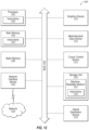
- FIG. 1 illustrates an example overall system environment of an HD map system interacting with multiple vehicle computing systems
- FIG. 2 illustrates an example system architecture of a vehicle computing system
- FIG. 3 illustrates an example of various layers of instructions in an HD map application programming interface of a vehicle computing system
- FIG. 4 illustrates an example of system architecture of an online HD map system
- FIG. 5 illustrates example components of an HD map
- FIGS. 6 A- 6 B illustrate example geographical regions defined in an HD map
- FIG. 7 illustrates example representations of lanes in an HD map
- FIGS. 8 A- 8 B illustrates example lane elements and relationships between lane elements in an HD map
- FIG. 9 illustrates points on dynamic objects in a LIDAR scan inaccurately aligning with points on the ground of an HD map
- FIG. 10 illustrates a ground plane in front of a vehicle
- FIG. 11 illustrates a flow chart of an example method of segmenting ground points from non-ground points to assist with localization of a vehicle
- FIG. 12 illustrates an example embodiment of a computing machine that can read instructions from a machine-readable medium and execute the instructions in a processor or controller.
- Embodiments of the present disclosure may maintain high definition (HD) maps that may include up-to-date information with high accuracy or precision.
- the HD maps may be used by an autonomous vehicle to safely navigate to various destinations without human input or with limited human input.
- safe navigation may refer to performance of navigation within a target safety threshold.
- the target safety threshold may be a certain number of driving hours without an accident.
- Such thresholds may be set by automotive manufacturers or government agencies.
- up-to-date information does not necessarily mean absolutely up-to-date, but up-to-date within a target threshold amount of time.
- a target threshold amount of time may be one week or less such that a map that reflects any potential changes to a roadway that may have occurred within the past week may be considered “up-to-date”. Such target threshold amounts of time may vary anywhere from one month to 1 minute, or possibly even less.
- the autonomous vehicle may be a vehicle capable of sensing its environment and navigating without human input.
- An HD map may refer to a map that may store data with high precision and accuracy, for example, with accuracies of approximately 2-30 cm.
- Some embodiments may generate HD maps that may contain spatial geometric information about the roads on which the autonomous vehicle may travel. Accordingly, the generated HD maps may include the information that may allow the autonomous vehicle to navigate safely without human intervention. Some embodiments may gather and use data from the lower resolution sensors of the self-driving vehicle itself as it drives around rather than relying on data that may be collected by an expensive and time-consuming mapping fleet process that may include a fleet of vehicles outfitted with high resolution sensors to create HD maps. The autonomous vehicles may have no prior map data for these routes or even for the region. Some embodiments may provide location as a service (LaaS) such that autonomous vehicles of different manufacturers may gain access to the most up-to-date map information collected, obtained, or created via the aforementioned processes.
- LaaS location as a service
- Some embodiments may generate and maintain HD maps that may be accurate and may include up-to-date road conditions for safe navigation of the autonomous vehicle.
- the HD maps may provide the current location of the autonomous vehicle relative to one or more lanes of roads precisely enough to allow the autonomous vehicle to drive safely in and to maneuver safety between one or more lanes of the roads.
- HD maps may store a very large amount of information, and therefore may present challenges in the management of the information.
- an HD map for a given geographic region may be too large to store on a local storage of the autonomous vehicle.
- Some embodiments may provide a portion of an HD map to the autonomous vehicle that may allow the autonomous vehicle to determine its current location in the HD map, determine the features on the road relative to the autonomous vehicle's position, determine if it is safe to move the autonomous vehicle based on physical constraints and legal constraints, etc. Examples of such physical constraints may include physical obstacles, such as walls, barriers, medians, curbs, etc. and examples of legal constraints may include an allowed direction of travel for a lane, lane restrictions, speed limits, yields, stops, following distances, etc.
- Some embodiments of the present disclosure may allow safe navigation for an autonomous vehicle by providing relatively low latency, for example, 5-40 milliseconds or less, for providing a response to a request; high accuracy in terms of location, for example, accuracy within 30 cm or better; freshness of data such that a map may be updated to reflect changes on the road within a threshold time frame, for example, within days, hours, minutes or seconds; and storage efficiency by reducing or minimizing the storage used by the HD Map.
- LIDAR localization accuracy may be greatly affected by dynamic objects like cars and trucks, and the effect can be worse when a vehicle upon which the LIDAR is mounted is surrounded by traffic.
- points of vehicles on a LIDAR scan which typically are on points near the tires or the bottom parts of the vehicles, tend to find correspondences to the ground points in the HD map, which may create a large error in the roll, pitch, and altitude (e.g., z value) in the estimated pose of the LIDAR-mounted vehicle.
- a ground-to-ground (G2G) matching and a non-ground-to-non-ground (N2N) matching may be used during localization to reduce the effect of dynamic objects in a LIDAR-based localization and to optimize a runtime performance and increase a convergence radius.
- G2G ground-to-ground
- N2N non-ground-to-non-ground
- FIG. 1 illustrates an example overall system environment of an HD map system 100 that may interact with multiple vehicles, according to one or more embodiments of the present disclosure.
- the HD map system 100 may comprise an online HD map system 110 that may interact with a plurality of vehicles 150 (e.g., vehicles 150 a - d ) of the HD map system 100 .
- the vehicles 150 may be autonomous vehicles or non-autonomous vehicles.
- the online HD map system 110 may be configured to receive sensor data that may be captured by sensors of the vehicles 150 and combine data received from the vehicles 150 to generate and maintain HD maps.
- the online HD map system 110 may be configured to send HD map data to the vehicles 150 for use in driving the vehicles 150 .
- the online HD map system 110 may be implemented as a distributed computing system, for example, a cloud-based service that may allow clients such as a vehicle computing system 120 (e.g., vehicle computing systems 120 a - d ) to make requests for information and services.
- a vehicle computing system 120 may make a request for HD map data for driving along a route and the online HD map system 110 may provide the requested HD map data to the vehicle computing system 120 .
- FIG. 1 and the other figures use like reference numerals to identify like elements.
- the online HD map system 110 may comprise a vehicle interface module 160 and an HD map store 165 .
- the online HD map system 110 may be configured to interact with the vehicle computing system 120 of various vehicles 150 using the vehicle interface module 160 .
- the online HD map system 110 may be configured to store map information for various geographical regions in the HD map store 165 .
- the online HD map system 110 may be configured to include other modules than those illustrated in FIG. 1 , for example, various other modules as illustrated in FIG. 4 and further described herein.
- a module may include code and routines configured to enable a corresponding system (e.g., a corresponding computing system) to perform one or more of the operations described therewith. Additionally or alternatively, any given module may be implemented using hardware including any number of processors, microprocessors (e.g., to perform or control performance of one or more operations), field-programmable gate arrays (FPGAs), application-specific integrated circuits (ASICs) or any suitable combination of two or more thereof. Alternatively or additionally, any given module may be implemented using a combination of hardware and software. In the present disclosure, operations described as being performed by a module may include operations that the module may direct a corresponding system to perform.
- the differentiation and separation of different modules indicated in the present disclosure is to help with explanation of operations being performed and is not meant to be limiting.
- the operations described with respect to two or more of the modules described in the present disclosure may be performed by what may be considered as a same module.
- the operations of one or more of the modules may be divided among what may be considered one or more other modules or submodules depending on the implementation.
- the online HD map system 110 may be configured to receive sensor data collected by sensors of a plurality of vehicles 150 , for example, hundreds or thousands of cars.
- the sensor data may include any data that may be obtained by sensors of the vehicles that may be related to generation of HD maps.
- the sensor data may include LIDAR data, captured images, etc. Additionally or alternatively, the sensor data may include information that may describe the current state of the vehicle 150 , the location and motion parameters of the vehicles 150 , etc.
- the vehicles 150 may be configured to provide the sensor data 115 that may be captured while driving along various routes and to send it to the online HD map system 110 .
- the online HD map system 110 may be configured to use the sensor data 115 received from the vehicles 150 to create and update HD maps describing the regions in which the vehicles 150 may be driving.
- the online HD map system 110 may be configured to build high definition maps based on the collective sensor data 115 that may be received from the vehicles 150 and to store the HD map information in the HD map store 165 .
- the online HD map system 110 may be configured to send HD map data to the vehicles 150 at the request of the vehicles 150 .
- the particular vehicle computing system 120 of the particular vehicle 150 may be configured to provide information describing the route being travelled to the online HD map system 110 .
- the online HD map system 110 may be configured to provide HD map data of HD maps related to the route (e.g., that represent the area that includes the route) that may facilitate navigation and driving along the route by the particular vehicle 150 .
- the online HD map system 110 may be configured to send portions of the HD map data to the vehicles 150 in a compressed format so that the data transmitted may consume less bandwidth.
- the online HD map system 110 may be configured to receive from various vehicles 150 , information describing the HD map data that may be stored at a local HD map store (e.g., the local HD map store 275 of FIG. 2 ) of the vehicles 150 .
- the online HD map system 110 may determine that the particular vehicle 150 may not have certain portions of the HD map data stored locally in a local HD map store of the particular vehicle computing system 120 of the particular vehicle 150 . In these or other embodiments, in response to such a determination, the online HD map system 110 may be configured to send a particular portion of the HD map data to the vehicle 150 .
- the online HD map system 110 may determine that the particular vehicle 150 may have previously received HD map data with respect to the same geographic area as the particular portion of the HD map data. In these or other embodiments, the online HD map system 110 may determine that the particular portion of the HD map data may be an updated version of the previously received HD map data that was updated by the online HD map system 110 since the particular vehicle 150 last received the previous HD map data. In some embodiments, the online HD map system 110 may send an update for that portion of the HD map data that may be stored at the particular vehicle 150 . This may allow the online HD map system 110 to reduce or minimize the amount of HD map data that may be communicated with the vehicle 150 and also to keep the HD map data stored locally in the vehicle updated on a regular basis.
- the vehicle 150 may include vehicle sensors 105 (e.g., vehicle sensors 105 a - d ), vehicle controls 130 (e.g., vehicle controls 130 a - d ), and a vehicle computing system 120 (e.g., vehicle computer systems 120 a - d ).
- vehicle sensors 105 may be configured to detect the surroundings of the vehicle 150 .
- the vehicle sensors 105 may detect information describing the current state of the vehicle 150 , for example, information describing the location and motion parameters of the vehicle 150 .
- the vehicle sensors 105 may comprise a camera, a light detection and ranging sensor (LIDAR), a global navigation satellite system (GNSS) receiver, for example, a global positioning system (GPS) navigation system, an inertial measurement unit (IMU), and others.
- the vehicle sensors 105 may include one or more cameras that may capture images of the surroundings of the vehicle.
- a LIDAR may survey the surroundings of the vehicle by measuring distance to a target by illuminating that target with a laser light pulses and measuring the reflected pulses.
- the GPS navigation system may determine the position of the vehicle 150 based on signals from satellites.
- the IMU may include an electronic device that may be configured to measure and report motion data of the vehicle 150 such as velocity, acceleration, direction of movement, speed, angular rate, and so on using a combination of accelerometers and gyroscopes or other measuring instruments.
- the vehicle controls 130 may be configured to control the physical movement of the vehicle 150 , for example, acceleration, direction change, starting, stopping, etc.
- the vehicle controls 130 may include the machinery for controlling the accelerator, brakes, steering wheel, etc.
- the vehicle computing system 120 may provide control signals to the vehicle controls 130 on a regular and/or continuous basis and may cause the vehicle 150 to drive along a selected route.
- the vehicle computing system 120 may be configured to perform various tasks including processing data collected by the sensors as well as map data received from the online HD map system 110 .
- the vehicle computing system 120 may also be configured to process data for sending to the online HD map system 110 .
- An example of the vehicle computing system 120 is further illustrated in FIG. 2 and further described in connection with FIG. 2 .
- the interactions between the vehicle computing systems 120 and the online HD map system 110 may be performed via a network, for example, via the Internet.
- the network may be configured to enable communications between the vehicle computing systems 120 and the online HD map system 110 .
- the network may be configured to utilize standard communications technologies and/or protocols.
- the data exchanged over the network may be represented using technologies and/or formats including the hypertext markup language (HTML), the extensible markup language (XML), etc.
- all or some of links may be encrypted using conventional encryption technologies such as secure sockets layer (SSL), transport layer security (TLS), virtual private networks (VPNs), Internet Protocol security (IPsec), etc.
- the entities may use custom and/or dedicated data communications technologies.
- FIG. 2 illustrates an example system architecture of the vehicle computing system 120 .
- the vehicle computing system 120 may include a perception module 210 , a prediction module 215 , a planning module 220 , a control module 225 , a localization module 260 , a local HD map store 275 , an HD map system interface 280 , and an HD map application programming interface (API) 205 .
- the various modules of the vehicle computing system 120 may be configured to process various types of data including sensor data 230 , a behavior model 235 , routes 240 , and physical constraints 245 .
- the vehicle computing system 120 may contain more or fewer modules. The functionality described as being implemented by a particular module may be implemented by other modules.
- the vehicle computing system 120 may include a perception module 210 .
- the perception module 210 may be configured to receive sensor data 230 from the vehicle sensors 105 of the vehicles 150 .
- the sensor data 230 may include data collected by cameras of the car, LIDAR, IMU, GPS navigation system, etc.
- the perception module 210 may also be configured to use the sensor data 230 to determine what objects are around the corresponding vehicle 150 , the details of the road on which the corresponding vehicle 150 is travelling, etc.
- the perception module 210 may be configured to process the sensor data 230 to populate data structures storing the sensor data 230 and to provide the information or instructions to a prediction module 215 of the vehicle computing system 120 .
- the prediction module 215 may be configured to interpret the data provided by the perception module 210 using behavior models of the objects perceived to determine whether an object may be moving or likely to move. For example, the prediction module 215 may determine that objects representing road signs may not be likely to move, whereas objects identified as vehicles, people, etc., may either be in motion or likely to move. The prediction module 215 may also be configured to use behavior models 235 of various types of objects to determine whether they may be likely to move. In addition, the prediction module 215 may also be configured to provide the predictions of various objects to a planning module 200 of the vehicle computing system 120 to plan the subsequent actions that the corresponding vehicle 150 may take next.
- the planning module 200 may be configured to receive information describing the surroundings of the corresponding vehicle 150 from the prediction module 215 and a route 240 that may indicate a destination of the vehicle 150 and that may indicate the path that the vehicle 150 may take to get to the destination.
- the planning module 200 may also be configured to use the information from the prediction module 215 and the route 240 to plan a sequence of actions that the vehicle 150 may to take within a short time interval, for example, within the next few seconds.
- the planning module 200 may be configured to specify a sequence of actions as one or more points representing nearby locations that the corresponding vehicle 150 may drive through next.
- the planning module 200 may be configured to provide, to the control module 225 , the details of a plan comprising the sequence of actions to be taken by the corresponding vehicle 150 .
- the plan may indicate the subsequent action or actions of the corresponding vehicle 150 , for example, whether the corresponding vehicle 150 may perform a lane change, a turn, an acceleration by increasing the speed or slowing down, etc.
- the control module 225 may be configured to determine the control signals that may be sent to the vehicle controls 130 of the corresponding vehicle 150 based on the plan that may be received from the planning module 200 . For example, if the corresponding vehicle 150 is currently at point A and the plan specifies that the corresponding vehicle 150 should next proceed to a nearby point B, the control module 225 may determine the control signals for the vehicle controls 130 that may cause the corresponding vehicle 150 to go from point A to point B in a safe and smooth way, for example, without taking any sharp turns or a zig zag path from point A to point B.
- the path that may be taken by the corresponding vehicle 150 to go from point A to point B may depend on the current speed and direction of the corresponding vehicle 150 as well as the location of point B with respect to point A. For example, if the current speed of the corresponding vehicle 150 is high, the corresponding vehicle 150 may take a wider turn compared to another vehicle driving slowly.
- the control module 225 may also be configured to receive physical constraints 245 as input.
- the physical constraints 245 may include the physical capabilities of the corresponding vehicle 150 .
- the corresponding vehicle 150 having a particular make and model may be able to safely make certain types of vehicle movements such as acceleration and turns that another vehicle with a different make and model may not be able to make safely.
- the control module 225 may be configured to incorporate the physical constraints 245 in determining the control signals for the vehicle controls 130 of the corresponding vehicle 150 .
- the control module 225 may be configured to send control signals to the vehicle controls 130 that may cause the corresponding vehicle 150 to execute the specified sequence of actions and may cause the corresponding vehicle 150 to move according to a predetermined set of actions.
- the aforementioned steps may be constantly repeated every few seconds and may cause the corresponding vehicle 150 to drive safely along the route that may have been planned for the corresponding vehicle 150 .
- the various modules of the vehicle computing system 120 including the perception module 210 , prediction module 215 , and planning module 220 may be configured to receive map information to perform their respective computations.
- the corresponding vehicle 150 may store the HD map data in the local HD map store 275 .
- the modules of the vehicle computing system 120 may interact with the map data using an HD map API 205 .
- the HD map API 205 may provide one or more application programming interfaces (APIs) that can be invoked by a module for accessing the map information.
- the HD map system interface 280 may be configured to allow the vehicle computing system 120 to interact with the online HD map system 110 via a network (not illustrated in the Figures).
- the local HD map store 275 may store map data in a format that may be specified by the online HD map system 110 .
- the HD map API 205 may be configured to process the map data format as provided by the online HD map system 110 .
- the HD map API 205 may be configured to provide the vehicle computing system 120 with an interface for interacting with the HD map data.
- the HD map API 205 may include several APIs including a localization API 250 , a landmark map API 255 , a 3D map API 265 , a route API 270 , a map update API 285 , etc.
- the localization API 250 may be configured to determine the current location of the corresponding vehicle 150 , for example, where the corresponding vehicle 150 is with respect to a given route.
- the localization API 250 may be configured to include a localized API that determines a location of the corresponding vehicle 150 within an HD map and within a particular degree of accuracy.
- the vehicle computing system 120 may also be configured to use the location as an accurate (e.g., within a certain level of accuracy) relative position for making other queries, for example, feature queries, navigable space queries, and occupancy map queries further described herein.
- the localization API 250 may be configured to receive inputs comprising one or more of, location provided by GPS, vehicle motion data provided by IMU, LIDAR scanner data, camera images, etc.
- the localization API 250 may be configured to return an accurate location of the corresponding vehicle 150 as latitude and longitude coordinates.
- the coordinates that may be returned by the localization API 250 may be more accurate compared to the GPS coordinates used as input, for example, the output of the localization API 250 may have precision ranging within from 2-30 cm.
- the vehicle computing system 120 may be configured to invoke the localization API 250 to determine the location of the corresponding vehicle 150 periodically based on the LIDAR using scanner data, for example, at a frequency of 10 Hertz (Hz).
- the vehicle computing system 120 may also be configured to invoke the localization API 250 to determine the vehicle location at a higher rate (e.g., 60 Hz) if GPS or IMU data is available at that rate.
- vehicle computing system 120 may be configured to store as internal state, location history records to improve accuracy of subsequent localization calls.
- the location history record may store history of location from the point-in-time, when the corresponding vehicle 150 was turned off/stopped, etc.
- the localization API 250 may include a localize-route API that may be configured to generate an accurate (e.g., within a specified degree of accuracy) route specifying lanes based on the HD maps.
- the localize-route API may be configured to receive as input a route from a source to a destination via one or more third-party maps and may be configured to generate a high precision (e.g., within a specified degree of precision such as within 30 cm) route represented as a connected graph of navigable lanes along the input routes based on HD maps.
- a high precision e.g., within a specified degree of precision such as within 30 cm
- the landmark map API 255 may be configured to provide a geometric and semantic description of the world around the corresponding vehicle 150 , for example, description of various portions of lanes that the corresponding vehicle 150 is currently travelling on.
- the landmark map APIs 255 comprise APIs that may be configured to allow queries based on landmark maps, for example, fetch-lanes API and fetch-features API.
- the fetch-lanes API may be configured to provide lane information relative to the corresponding vehicle 150 and the fetch-features API.
- the fetch-lanes API may also be configured to receive, as input, a location, for example, the location of the corresponding vehicle 150 specified using latitude and longitude and return lane information relative to the input location.
- the fetch-lanes API may be configured to specify a distance parameter indicating the distance relative to the input location for which the lane information may be retrieved.
- the fetch-features API may be configured to receive information identifying one or more lane elements and to return landmark features relative to the specified lane elements.
- the landmark features may include, for each landmark, a spatial description that may be specific to the type of landmark.
- the 3D map API 265 may be configured to provide access to the spatial 3-dimensional (3D) representation of the road and various physical objects around the road as stored in the local HD map store 275 .
- the 3D map APIs 265 may include a fetch-navigable-surfaces API and a fetch-occupancy-grid API.
- the fetch-navigable-surfaces API may be configured to receive as input identifiers for one or more lane elements and return navigable boundaries for the specified lane elements.
- the fetch-occupancy-grid API may also be configured to receive a location as input, for example, a latitude and a longitude of the corresponding vehicle 150 , and return information describing occupancy for the surface of the road and all objects available in the HD map near the location.
- the information describing occupancy may include a hierarchical volumetric grid of some or all positions considered occupied in the HD map.
- the occupancy grid may include information at a high resolution near the navigable areas, for example, at curbs and bumps, and relatively low resolution in less significant areas, for example, trees and walls beyond a curb.
- the fetch-occupancy-grid API may be configured to detect obstacles and to change direction, if necessary.
- the 3D map APIs 265 may also include map-update APIs, for example, download-map-updates API and upload-map-updates API.
- the download-map-updates API may be configured to receive as input a planned route identifier and download map updates for data relevant to all planned routes or for a specific planned route.
- the upload-map-updates API may be configured to upload data collected by the vehicle computing system 120 to the online HD map system 110 .
- the upload-map-updates API may allow the online HD map system 110 to keep the HD map data stored in the online HD map system 110 up-to-date based on changes in map data that may be observed by sensors of vehicles 150 driving along various routes.
- the route API 270 may be configured to return route information including a full route between a source and destination and portions of a route as the corresponding vehicle 150 travels along the route.
- the 3D map API 265 may be configured to allow querying of the online HD map system 110 .
- the route APIs 270 may include an add-planned-routes API and a get-planned-route API.
- the add-planned-routes API may be configured to provide information describing planned routes to the online HD map system 110 so that information describing relevant HD maps may be downloaded by the vehicle computing system 120 and kept up to date.
- the add-planned-routes API may be configured to receive as input, a route specified using polylines expressed in terms of latitudes and longitudes and also a time-to-live (TTL) parameter specifying a time period after which the route data may be deleted. Accordingly, the add-planned-routes API may be configured to allow the vehicle 150 to indicate the route the vehicle 150 is planning on taking in the near future as an autonomous trip. The add-planned-route API may also be configured to align the route to the HD map, record the route and its TTL value, and determine that the HD map data for the route stored in the vehicle computing system 120 is up-to-date. The get-planned-routes API may be configured to return a list of planned routes and to provide information describing a route identified by a route identifier.
- TTL time-to-live
- the map update API 285 may be configured to manage operations related to updating of map data, both for the local HD map store 275 and for the HD map store 165 stored in the online HD map system 110 . Accordingly, modules in the vehicle computing system 120 may be configured to invoke the map update API 285 for downloading data from the online HD map system 110 to the vehicle computing system 120 for storing in the local HD map store 275 .
- the map update API 285 may also be configured to allow the vehicle computing system 120 to determine whether the information monitored by the vehicle sensors 105 indicates a discrepancy in the map information provided by the online HD map system 110 and upload data to the online HD map system 110 that may result in the online HD map system 110 updating the map data stored in the HD map store 165 that is provided to other vehicles 150 .
- FIG. 3 illustrates an example of various layers of instructions in the HD map API 205 of the vehicle computing system 120 .
- Different manufacturers of vehicles may have different procedures or instructions for receiving information from vehicle sensors 105 and for controlling the vehicle controls 130 .
- different vendors may provide different computer platforms with autonomous driving capabilities, for example, collection and analysis of vehicle sensor data. Examples of a computer platform for autonomous vehicles include platforms provided vendors, such as NVIDIA, QUALCOMM, and INTEL. These platforms may provide functionality for use by autonomous vehicle manufacturers in the manufacture of autonomous vehicles 150 .
- a vehicle manufacturer may use any one or several computer platforms for autonomous vehicles 150 .
- the online HD map system 110 may be configured to provide a library for processing HD maps based on instructions specific to the manufacturer of the vehicle and instructions specific to a vendor specific platform of the vehicle.
- the library may provide access to the HD map data and may allow the vehicle 150 to interact with the online HD map system 110 .
- the HD map API 205 may be configured to be implemented as a library that includes a vehicle manufacturer adapter 310 , a computer platform adapter 320 , and a common HD map API layer 330 .
- the common HD map API layer 330 may be configured to include generic instructions that may be used across a plurality of vehicle computer platforms and vehicle manufacturers.
- the computer platform adapter 320 may be configured to include instructions that may be specific to each computer platform.
- the common HD map API layer 330 may be configured to invoke the computer platform adapter 320 to receive data from sensors supported by a specific computer platform.
- the vehicle manufacturer adapter 310 may be configured to include instructions specific to a vehicle manufacturer.
- the common HD map API layer 330 may be configured to invoke functionality provided by the vehicle manufacturer adapter 310 to send specific control instructions to the vehicle controls 130 .
- the online HD map system 110 may be configured to store computer platform adapters 320 for a plurality of computer platforms and vehicle manufacturer adapters 310 for a plurality of vehicle manufacturers.
- the online HD map system 110 may be configured to determine the particular vehicle manufacturer and the particular computer platform for a specific autonomous vehicle 150 .
- the online HD map system 110 may also be configured to select the vehicle manufacturer adapter 310 for the particular vehicle manufacturer and the computer platform adapter 320 the particular computer platform of that specific vehicle 150 .
- the online HD map system 110 may be configured to send instructions of the selected vehicle manufacturer adapter 310 and the selected computer platform adapter 320 to the vehicle computing system 120 of that specific autonomous vehicle.
- the vehicle computing system 120 of that specific autonomous vehicle may be configured to install the received vehicle manufacturer adapter 310 and the computer platform adapter 320 .
- the vehicle computing system 120 may also be configured to periodically verify whether the online HD map system 110 has an update to the installed vehicle manufacturer adapter 310 and the computer platform adapter 320 . In addition, if a more recent update is available compared to the version installed on the vehicle 150 , the vehicle computing system 120 may be configured to request and receive the latest update and to install it.
- FIG. 4 illustrates an example system architecture of the online HD map system 110 .
- the online HD map system 110 may be configured to include a map creation module 410 , a map update module 420 , a map data encoding module 430 , a load balancing module 440 , a map accuracy management module 450 , the vehicle interface module 160 , and the HD map store 165 .
- Some embodiments of online HD map system 110 may be configured to include more or fewer modules than shown in FIG. 4 . Functionality indicated as being performed by a particular module may be implemented by other modules.
- the online HD map system 110 may be configured to be a distributed system comprising a plurality of processing systems.
- the map creation module 410 may be configured to create HD map data of HD maps from the sensor data collected from several vehicles 150 that are driving along various routes.
- the map update module 420 may be configured to update previously computed HD map data by receiving more recent information (e.g., sensor data) from vehicles 150 that recently travelled along routes on which map information changed. For example, certain road signs may have changed or lane information may have changed as a result of construction in a region, and the map update module 420 may be configured to update the HD maps and corresponding HD map data accordingly.
- the map data encoding module 430 may be configured to encode the HD map data to be able to store the data efficiently (e.g., compress the HD map data) as well as send the HD map data to vehicles 150 .
- the load balancing module 440 may be configured to balance loads across vehicles 150 such that requests to receive data from vehicles 150 are distributed across different vehicles 150 in a relatively uniform manner (e.g., the load distribution between different vehicles 150 is within a threshold amount of each other).
- the map accuracy management module 450 may be configured to maintain relatively high accuracy of the HD map data using various techniques even though the information received from individual vehicles may not have the same degree of accuracy.
- FIG. 5 illustrates example components of an HD map 510 .
- the HD map 510 may include HD map data of maps of several geographical regions.
- reference to a map or an HD map, such as HD map 510 may include reference to the map data that corresponds to such map. Further, reference to information of a respective map may also include reference to the map data of that map.
- the HD map 510 of a geographical region may include a landmark map (LMap) 520 and an occupancy map (OMap) 530 .
- the landmark map 520 may comprise information describing lanes including spatial location of lanes and semantic information about each lane.
- the spatial location of a lane may comprise the geometric location in latitude, longitude, and elevation at high prevision, for example, precision within 30 cm or better.
- the semantic information of a lane comprises restrictions such as direction, speed, type of lane (for example, a lane for going straight, a left turn lane, a right turn lane, an exit lane, and the like), restriction on crossing to the left, connectivity to other lanes, etc.
- the landmark map 520 may comprise information describing stop lines, yield lines, spatial location of cross walks, safely navigable space, spatial location of speed bumps, curb, road signs comprising spatial location, type of all signage that is relevant to driving restrictions, etc.
- Examples of road signs described in an HD map 510 may include stop signs, traffic lights, speed limits, one-way, do-not-enter, yield (vehicle, pedestrian, animal), etc.
- the occupancy map 530 may comprise a spatial 3-dimensional (3D) representation of the road and physical objects around the road.
- the data stored in an occupancy map 530 may also be referred to herein as occupancy grid data.
- the 3D representation may be associated with a confidence score indicative of a likelihood of the object existing at the location.
- the occupancy map 530 may be represented in a number of other ways.
- the occupancy map 530 may be represented as a 3D mesh geometry (collection of triangles) which may cover the surfaces.
- the occupancy map 530 may be represented as a collection of 3D points which may cover the surfaces.
- the occupancy map 530 may be represented using a 3D volumetric grid of cells at 5-10 cm resolution. Each cell may indicate whether or not a surface exists at that cell, and if the surface exists, a direction along which the surface may be oriented.
- the occupancy map 530 may take a large amount of storage space compared to a landmark map 520 .
- data of 1 GB/Mile may be used by an occupancy map 530 , resulting in the map of the United States (including 4 million miles of road) occupying 4 ⁇ 10 15 bytes or 4 petabytes. Therefore, the online HD map system 110 and the vehicle computing system 120 may use data compression techniques to be able to store and transfer map data thereby reducing storage and transmission costs. Accordingly, the techniques disclosed herein may help improve the self-driving of autonomous vehicles by improving the efficiency of data storage and transmission with respect to self-driving operations and capabilities.
- the HD map 510 does may not use or rely on data that may typically be included in maps, such as addresses, road names, ability to geo-code an address, and ability to compute routes between place names or addresses.
- the vehicle computing system 120 or the online HD map system 110 may access other map systems, for example, GOOGLE MAPS, to obtain this information.
- a vehicle computing system 120 or the online HD map system 110 may receive navigation instructions from a tool such as GOOGLE MAPS into a route and may convert the information to a route based on the HD map 510 or may convert the information such that it may be compatible for us on the HD map 510 .
- the online HD map system 110 may divide a large physical area into geographical regions and may store a representation of each geographical region. Each geographical region may represent a contiguous area bounded by a geometric shape, for example, a rectangle or square. In some embodiments, the online HD map system 110 may divide a physical area into geographical regions of similar size independent of the amount of data needed to store the representation of each geographical region. In some embodiments, the online HD map system 110 may divide a physical area into geographical regions of different sizes, where the size of each geographical region may be determined based on the amount of information needed for representing the geographical region. For example, a geographical region representing a densely populated area with a large number of streets may represent a smaller physical area compared to a geographical region representing sparsely populated area with very few streets. In some embodiments, the online HD map system 110 may determine the size of a geographical region based on an estimate of an amount of information that may be used to store the various elements of the physical area relevant for the HD map.
- the online HD map system 110 may represent a geographic region using an object or a data record that may include various attributes including: a unique identifier for the geographical region; a unique name for the geographical region; a description of the boundary of the geographical region, for example, using a bounding box of latitude and longitude coordinates; and a collection of landmark features and occupancy grid data.
- FIGS. 6 A- 6 B illustrate example geographical regions 610 a and 610 b that may be defined in an HD map according to one or more embodiments.
- FIG. 6 A illustrates a square geographical region 610 a .
- FIG. 6 B illustrates two neighboring geographical regions 610 a and 610 b .
- the online HD map system 110 may store data in a representation of a geographical region that may allow for transitions from one geographical region to another as a vehicle 150 drives across geographical region boundaries.
- each geographic region may include a buffer of a predetermined width around it.
- the buffer may comprise redundant map data around one or more sides e of a geographic region.
- the buffer may be around every side of a particular geographic region. Therefore, in some embodiments, where the geographic region may be a certain shape, the geographic region may be bounded by a buffer that may be a larger version of that shape.
- FIG. 6 A illustrates a boundary 620 for a buffer of approximately 50 m around the geographic region 610 a and a boundary 630 for a buffer of approximately 100 m around the geographic region 610 a.
- the vehicle computing system 120 may switch the current geographical region of the corresponding vehicle 150 from one geographical region to a neighboring geographical region when the corresponding vehicle 150 crosses a predetermined threshold distance within the buffer. For example, as shown in FIG. 6 B , the corresponding vehicle 150 may start at location 650 a in the geographical region 610 a . The corresponding vehicle 150 may traverse along a route to reach a location 650 b where it may cross the boundary of the geographical region 610 but may stay within the boundary 620 of the buffer. Accordingly, the vehicle computing system 120 of the corresponding vehicle 150 may continue to use the geographical region 610 a as the current geographical region of the vehicle.
- the vehicle computing system 120 may switch the current geographical region of the corresponding vehicle 150 to geographical region 610 b from geographical region 610 a .
- the use of a buffer may reduce or prevent rapid switching of the current geographical region of a vehicle 150 as a result of the vehicle 150 travelling along a route that may closely track a boundary of a geographical region.
- the HD map system 100 may represent lane information of streets in HD maps. Although the embodiments described may refer to streets, the techniques may be applicable to highways, alleys, avenues, boulevards, paths, etc., on which vehicles 150 may travel.
- the HD map system 100 may use lanes as a reference frame for purposes of routing and for localization of the vehicle 150 .
- the lanes represented by the HD map system 100 may include lanes that are explicitly marked, for example, white and yellow striped lanes, lanes that may be implicit, for example, on a country road with no lines or curbs but may nevertheless have two directions of travel, and implicit paths that may act as lanes, for example, the path that a turning car may make when entering a lane from another lane.
- the HD map system 100 may also store information relative to lanes, for example, landmark features such as road signs and traffic lights relative to the lanes, occupancy grids relative to the lanes for obstacle detection, and navigable spaces relative to the lanes so the vehicle 150 may plan/react in emergencies when the vehicle 150 makes an unplanned move out of the lane. Accordingly, the HD map system 100 may store a representation of a network of lanes to allow the vehicle 150 to plan a legal path between a source and a destination and to add a frame of reference for real-time sensing and control of the vehicle 150 .
- landmark features such as road signs and traffic lights relative to the lanes
- occupancy grids relative to the lanes for obstacle detection
- navigable spaces relative to the lanes
- the HD map system 100 stores information and provides APIs that may allow a vehicle 150 to determine the lane that the vehicle 150 is currently in, the precise location of the vehicle 150 relative to the lane geometry, and other relevant features/data relative to the lane and adjoining and connected lanes.
- FIG. 7 illustrates example lane representations in an HD map.
- FIG. 7 illustrates a vehicle 710 at a traffic intersection.
- the HD map system 100 provides the vehicle 710 with access to the map data that may be relevant for autonomous driving of the vehicle 710 . This may include, for example, features 720 a and 720 b that may be associated with the lane but may not be the closest features to the vehicle 710 . Therefore, the HD map system 100 may store a lane-centric representation of data that may represent the relationship of the lane to the feature so that the vehicle 710 can efficiently extract the features given a lane.
- the HD map data may represent portions of the lanes as lane elements.
- the lane elements may specify the boundaries of the lane and various constraints including the legal direction in which a vehicle may travel within the lane element, the speed with which the vehicle may drive within the lane element, whether the lane element may be for left turn only, or right turn only, etc.
- the HD map data may represent a lane element as a continuous geometric portion of a single vehicle lane.
- the HD map system 100 may store objects or data structures that may represents lane elements that may comprise information representing geometric boundaries of the lanes; driving direction along the lane; vehicle restriction for driving in the lane, for example, speed limit, relationships with connecting lanes including incoming and outgoing lanes; a termination restriction, for example, whether the lane ends at a stop line, a yield sign, or a speed bump; and relationships with road features that are relevant for autonomous driving, for example, traffic light locations, road sign locations, etc., as part of the HD map data.
- Examples of lane elements represented by the HD map data may include, a piece of a right lane on a freeway, a piece of a lane on a road, a left turn lane, the turn from a left turn lane into another lane, a merge lane from an on-ramp an exit lane on an off-ramp, and a driveway.
- the HD map data may represent a one-lane road using two lane elements, one for each direction.
- the HD map system 100 may represents median turn lanes that may be shared similar to a one-lane road.
- FIGS. 8 A-B illustrate lane elements and relations between lane elements in an HD map.
- FIG. 8 A illustrates an example of a T-junction in a road illustrating a lane element 810 a that may be connected to lane element 810 c via a turn lane 810 b and is connected to lane 810 e via a turn lane 810 d .
- FIG. 8 B illustrates an example of a Y-junction in a road illustrating label 810 f connected to lane 810 h directly and connected to lane 810 i via lane 810 g .
- the HD map system 100 may determine a route from a source location to a destination location as a sequence of connected lane elements that can be traversed to reach from the source location to the destination location.
- LIDAR localization accuracy may be greatly affected by dynamic objects like cars and trucks.
- the effect can be worse when a vehicle upon which the LIDAR is mounted is surrounded by traffic.
- points of vehicles on a LIDAR scan which typically are on points near the tires or the bottom parts of the vehicles, tend to find correspondences to the ground points in the HD map. These wrong correspondences may cause the localizer to move towards these dynamic objects.
- the effects of the dynamic objects may be more dramatic when the field-of-view (FOV) of the LIDAR is reduced (either by traffic or limited by hardware).
- FOV field-of-view
- FIG. 9 illustrates points on dynamic objects in a LIDAR scan inaccurately aligning with points on the ground of an HD map.
- a relatively small FOV LIDAR scan may align inaccurately to the HD map points.
- the points on the cars surrounding the LIDAR-mounted vehicle may tend to align to the points on the ground in the HD map, which may create a large error in the altitude value (e.g., z value) and the pitch value in the estimated car pose of the LIDAR-mounted vehicle (e.g., the pitch value may be inaccurately raised, and the altitude value may be inaccurately lowered).
- the misalignment may also create a large error in the roll in the estimated car pose of the LIDAR-mounted vehicle.
- a ground-to-ground (G2G) matching and a non-ground-to-non-ground (N2N) matching may be used during localization to reduce the effect of dynamic objects in a LIDAR-based localization and to optimize a runtime performance and increase a convergence radius.
- G2G ground-to-ground
- N2N non-ground-to-non-ground
- the localization module 260 of the vehicle computing system 120 may segment a current LIDAR scan by detecting the ground and clustering the points into two point clouds: ground points and non-ground points. This ground plane segmentation may be achieved relatively fast with reasonable accuracy because of its relatively simple geometry.
- the system may use a random sample consensus (RANSAC) algorithm or a range-based segmentation algorithm.
- RANSAC random sample consensus
- the same segmentation may be applied to the HD map, in the map making process and/or in real-time, so that ground segmentation labels can be looked up and/or generated in live localization.
- the system may match only the points with the consistent labels (e.g., ground or non-ground) between the LIDAR scan and the HD map. By doing this, LIDAR scan points from the cars in FIG. 9 may no longer correspond to the map ground points. As a result, pose errors from incorrect correspondences, especially in the roll, pitch, and altitude of the pose, may be greatly reduced.
- the localization module 260 of the vehicle computing system 120 may determine the roll and the pitch of a vehicle by inspecting the ground plane. For example, if the ground plane is at an angle (e.g., a slope), the vehicle may be likely to be at the same angle and therefore have the same roll and pitch values.
- the localization module 260 may determine a ground plane based on sensor data, for example, using points from a LIDAR scan.
- FIG. 10 illustrates a ground plane in front of a vehicle.
- the localization module 260 may identify points that are close to the vehicle and immediately in front of the vehicle (e.g., the region outlined in FIG. 10 ) and fit a plane through those points.
- the localization module 260 may determine a ground plane by determining an approximate location of the vehicle, for example using GPS, and then loading an OMap point cloud at that location and identifying the ground plane in that portion of the point cloud.
- the localization module 260 may determine a ground plane by collecting sensor data, for example a LIDAR scan, and identifying a ground plane in the LIDAR scan.
- the localization module 260 may have a predetermined estimate of the height of the LIDAR (e.g., based on vehicle manufacturer information).
- the localization module 260 may use the height to determine locations of ground points and may fit a plane through these points.
- GPS data may provide inaccurate altitude values for a vehicle, but the localization module 260 may use GPS data to determine a location (e.g., a latitude and a longitude) of the vehicle, and then may determine the altitude from the OMap data at that location (e.g., that latitude and that longitude). Some embodiments may then determine the roll and pitch value of the vehicle based on a ground plane as follows:
- the localization module 260 may determine the approximate location of the vehicle, for example, based on GNSS or a combination of GNSS and IMU data.
- the localization module 260 may load a portion of the HD map (e.g., OMap data representing a 3D point cloud) including the determined location.
- the HD map may be determined based on vehicles that previously travelled through the region in which the vehicle is present.
- the localization module 260 may determine the points representing the ground plane at the location of the vehicle from the HD map data.
- the localization module 260 may determine the roll, pitch, and altitude values of the ground plane based on the OMap data.
- the localization module 260 may use the roll, pitch, and altitude values of the ground plane as the roll, pitch, and altitude values of the vehicle.
- the localization module 260 may use matching, such as by performing any iterative closet point (ICP) algorithm that matches two point clouds by directly performing a Singular Value Decomposition (SVD) on the correspondences and estimating the transform.
- ICP iterative closet point
- SSD Singular Value Decomposition
- One such algorithm is disclosed in Segal, A., Haehnel, D., & Thrun, S. (2009), Generalized-ICP. Robotics: Science and Systems, 5, 168-176 which is incorporated by reference herein in its entirety for all that it discloses.
- the localization module 260 may detect other vehicles in front of the vehicle, for example in traffic. Performing conventional ICP may result in finding correspondences between points on wheels of these vehicles and ground points since the two types of points are close together.
- the localization module 260 may segment each point cloud into two chunks, ground points and non-ground points. In these embodiments, the localization module 260 may group the ground-to-ground (G2G) and non-ground-to-non-ground (N2N) correspondences together and may perform the normal ICP transform estimation separately for the two sets of points. By doing this, the localization module 260 may reduce the effect of dynamic objects (e.g., other vehicles). In some embodiments, the localization module 260 may apply different weights on the correspondences, for example, by making N2N correspondences have a higher weight than G2G correspondences (e.g., by making N2N correspondences have two times higher weight than G2G correspondences). In some embodiments, this process may be particularly useful for bootstrapping.
- G2G ground-to-ground
- N2N non-ground-to-non-ground
- an ICP algorithm may iteratively repeat the following two steps: (1) compute correspondences between two scans, and (2) compute a transformation which minimizes distance between corresponding points. Iteratively repeating these two steps may typically result in convergence to a desired transformation.
- steps of an ICP algorithm may include the following:
- T 0 The correct transformation, T, which aligns A and B 1 T ⁇ T 0 ; 2 while not converged do 3 for i ⁇ 1 to N do 4 m i ⁇ FindClosestPointInA (T ⁇ b i ); 5 if ⁇ m i ⁇ T ⁇ b i ⁇ ⁇ d max then 6 w i ⁇ 1; 7 else 8 w i ⁇ 0; 9 end 10 end 11 T ⁇ argmin T ⁇ ⁇ ⁇ ⁇ i ⁇ w i ⁇ ⁇ T ⁇ b i - m i ⁇ 2 ⁇ ⁇ ; 12 end
- the point-to-plane variant of ICP may improves performance by taking advantage of surface normal information.
- the point-to-plane algorithm may minimize error along the surface normal (e.g., the projection of (T ⁇ b i ⁇ m i ) onto the sub-space spanned by the surface normal). This improvement may implemented by changing line 11 of above ICP algorithm as follows:
- the localization module 260 may perform ICP or any technique of point cloud matching that separately matches ground points and non-ground points. Separating the ground points from non-ground points may avoid matching of non-ground points (e.g., points on wheels of vehicles) with ground points. In some embodiments, this may be accomplished as follows:
- the localization module 260 may assign higher weights to non-ground points compared to ground points while performing ICP, as follows:
- another way to use the matching is to separate the 6D degree of freedom (DOF) into two sub-problems: one problem for roll, pitch, and altitude (e.g., z coordinate), and another problem from x, y, and yaw coordinates.
- the ground points may usually be flat 2D planes
- the ground-to-ground matching may help the localization module 260 out the correct roll, pitch and z values if the x, y, and yaw value are known.
- the localization module 260 may first use the initial guess pose to do the non-ground matching to fix the correct x, y, and yaw value.
- the localization module 260 may next correct the roll, pitch, and z values by using the ground matching. This may magnify the effect of the non-ground points on the X, Y convergence, but subject to that the environment containing many non-ground features.
- the points on dynamic objects do not match any point in the OMap point cloud, and therefore get eliminated from the result.
- features on the ground e.g., cracks in road, pot holes, curves on the road, etc. may help localization to converge.
- many points on a dynamic object e.g., points on a vehicle
- the nearest neighbor search for those points may be faster (e.g., due to a property of a kd-tree).
- the localization module 260 may perform other actions to help with localization. For example, the localization module 260 may directly uses the ground points from the HD map to reset any localization approach's roll, pitch, and z value by looking-up the ground patch at that x, y, and yaw location (e.g., if a localization algorithm only generates a 2D pose: x, y, and yaw, the localization module 260 may directly look up the ground map, and find the ground patch at the x, y location). The localization module 260 may do a plane fitting on the ground points to find out the roll, pitch, and z values for that ground patch.
- the localization module 260 may do a plane fitting on the ground points to find out the roll, pitch, and z values for that ground patch.
- Roll and pitch values may be less accurate when the vehicle is on the bumps or in holes such as on non-flat roads.
- FIG. 11 illustrates a flow chart of an example method 1100 of segmenting ground points from non-ground points to assist with localization of a vehicle.
- the method 1100 may be employed by the localization module 260 of the vehicle computing system 120 to assist with localization of the vehicle 150 .
- the method 1100 may be performed by any suitable system, apparatus, or device.
- one or more elements of the HD map system 100 of FIG. 1 may be configured to perform one or more of the operations of the method 1100 .
- the computer system 1200 of FIG. 12 may be configured to perform one or more of the operations associated with the method 1100 .
- the actions and operations associated with one or more of the blocks of the method 1100 may be divided into additional blocks, combined into fewer blocks, or eliminated, depending on the particular implementation.
- the method 1100 may include, at action 1102 , receiving, from a LIDAR mounted on a vehicle, a first 3D point cloud comprising points of a region around the vehicle as observed by the LIDAR.
- the localization module 260 may receive, at action 1102 , a first 3D point cloud comprising points of a region around the vehicle 150 from a LIDAR mounted on a vehicle 150 as the vehicle 150 navigates along a road.
- the method 1100 may include, at action 1104 , accessing an HD map comprising a second 3D point cloud comprising points of the region around the vehicle.
- the localization module 260 may access, at action 1104 , an OMap of an HD map comprising a second 3D point cloud comprising points of the region around the vehicle 150 as the vehicle 150 navigates along a road.
- the OMap may be accessed by being downloaded from the online HD map store 165 , or by being previously downloaded and then retrieved from the local HD map store 275 .
- the method 1100 may include, at action 1106 , segmenting LIDAR ground points from LIDAR non-ground points in the first 3D point cloud.
- the method 1100 may include, at action 1108 , segmenting map ground points from map non-ground points in the second 3D point cloud.
- the action 1106 and/or the action 1108 may be performed using a random sample consensus (RANSAC) algorithm.
- the action 1106 and/or the action 1108 may be performed using a range-based segmentation algorithm.
- the localization module 260 may segment, at action 1106 , LIDAR ground points from LIDAR non-ground points in the first 3D point cloud.
- the localization module 260 may segment, at action 1106 , map ground points from map non-ground points in the second 3D point cloud.
- the segmenting of the map ground points from the map non-ground points may be performed at the online HD map system previously, and the localization module 260 may simply access labels or other indicators of this prior segmentation at action 1108 .
- the method 1100 may include, at action 1110 , determining a pose of the vehicle by performing an ICP algorithm to match the LIDAR ground points to the map ground points and by performing the ICP algorithm to match the LIDAR non-ground points to the map non-ground points.
- the performing of the ICP algorithm to match the LIDAR ground points to the map ground points may be performed separately from the performing of the ICP algorithm to match the LIDAR non-ground points to the map non-ground points.
- a higher weight may be applied to correspondences between the LIDAR non-ground points and the map non-ground points than to correspondences between the LIDAR ground points and the map ground points.
- a roll, a pitch, and an altitude of the pose may be determined by performing the ICP algorithm to match the LIDAR ground points to the map ground points.
- an x coordinate, a y coordinate, and a yaw of the pose may be determined by performing the ICP algorithm to match the LIDAR non-ground points to the map non-ground points.
- the matching of the ground points and the non-ground points may be accomplished using a method other than an ICP algorithm.
- the localization module 260 may determine, at action 1110 , a pose of the vehicle 150 by performing an ICP algorithm to match the LIDAR ground points to the map ground points and by performing (either separately or using higher weights) the ICP algorithm to match the LIDAR non-ground points to the map non-ground points.
- the method 1100 may employ the determined roll, pitch, and altitude (e.g., of the vehicle pose) of the vehicle 150 in gathering data to update the HD map store 165 , and/or in navigating the vehicle 150 based on the more determined roll, pitch, and altitude of the vehicle 150 . Further, the method 1100 may be employed repeatedly as the vehicle 150 navigates along a road. For example, the method 1100 may be employed when the vehicle 150 (or another non-autonomous vehicle) starts driving, and then may be employed repeatedly during the navigation of the vehicle 150 (or another non-autonomous vehicle). The vehicle 150 may navigate by sending control signals to controls of the vehicle 150 .
- the vehicle 150 may navigate by sending control signals to controls of the vehicle 150 .
- the method 1100 may be employed by the vehicle computing system 120 of the vehicle 150 to segment the LIDAR ground points from the LIDAR non-ground points to reduce or eliminate inadvertent matching of points on dynamic objects from the LIDAR with points on the ground from the HD map resulting in a more accurate determining of the roll, the pitch, and the altitude of the vehicle 150 .
- FIG. 12 is a block diagram illustrating components of an example computer system able to read instructions from a machine-readable medium and execute them in a processor (or controller). Specifically, FIG. 12 shows a diagrammatic representation of a machine in the example form of a computer system 1200 within which instructions 1224 (e.g., software) for causing the machine to perform any one or more of the methodologies discussed herein may be executed. In alternative embodiments, the machine operates as a standalone device or may be connected (e.g., networked) to other machines. In a networked deployment, the machine may operate in the capacity of a server machine or a client machine in a server-client network environment, or as a peer machine in a peer-to-peer (or distributed) network environment.
- instructions 1224 e.g., software
- the machine operates as a standalone device or may be connected (e.g., networked) to other machines. In a networked deployment, the machine may operate in the capacity of a server machine or a client machine in
- the machine may be a server computer, a client computer, a personal computer (PC), a tablet PC, a set-top box (STB), a personal digital assistant (PDA), a cellular telephone, a smartphone, a web appliance, a network router, switch or bridge, or any machine capable of executing instructions 1224 (sequential or otherwise) that specify actions to be taken by that machine.
- PC personal computer
- PDA personal digital assistant
- STB set-top box
- a cellular telephone a smartphone
- smartphone a web appliance
- network router switch or bridge
- the example computer system 1200 may be part of or may be any applicable system described in the present disclosure.
- the online HD map system 110 and/or the vehicle computing systems 120 described above may comprise the computer system 1200 or one or more portions of the computer system 1200 .
- different implementations of the computer system 1200 may include more or fewer components than those described herein.
- a particular computer system 1200 may not include one or more of the elements described herein and/or may include one or more elements that are not explicitly discussed.
- the example computer system 1200 includes a processor 1202 (e.g., a central processing unit (CPU), a graphics processing unit (GPU), a digital signal processor (DSP), one or more application specific integrated circuits (ASICs), one or more radio-frequency integrated circuits (RFICs), or any combination of these), a main memory 1204 , and a static memory 1206 , which are configured to communicate with each other via a bus 1208 .
- the computer system 1200 may further include graphics display unit 1210 (e.g., a plasma display panel (PDP), a liquid crystal display (LCD), a projector, or a cathode ray tube (CRT)).
- graphics display unit 1210 e.g., a plasma display panel (PDP), a liquid crystal display (LCD), a projector, or a cathode ray tube (CRT)
- the computer system 1200 may also include alphanumeric input device 1212 (e.g., a keyboard), a cursor control device 1214 (e.g., a mouse, a trackball, a joystick, a motion sensor, or other pointing instrument), a storage unit 1216 , a signal generation device 1218 (e.g., a speaker), and a network interface device 1220 , which also are configured to communicate via the bus 1208 .
- alphanumeric input device 1212 e.g., a keyboard
- a cursor control device 1214 e.g., a mouse, a trackball, a joystick, a motion sensor, or other pointing instrument
- storage unit 1216 e.g., a disk drive, or other pointing instrument
- a signal generation device 1218 e.g., a speaker
- network interface device 1220 which also are configured to communicate via the bus 1208 .
- the storage unit 1216 includes a machine-readable medium 1222 on which is stored instructions 1224 (e.g., software) embodying any one or more of the methodologies or functions described herein.
- the instructions 1224 (e.g., software) may also reside, completely or at least partially, within the main memory 1204 or within the processor 1202 (e.g., within a processor's cache memory) during execution thereof by the computer system 1200 , the main memory 1204 and the processor 1202 also constituting machine-readable media.
- the instructions 1224 (e.g., software) may be transmitted or received over a network 1226 via the network interface device 1220 .
- machine-readable medium 1222 is shown in an example embodiment to be a single medium, the term “machine-readable medium” should be taken to include a single medium or multiple media (e.g., a centralized or distributed database, or associated caches and servers) able to store instructions (e.g., instructions 1224 ).
- the term “machine-readable medium” shall also be taken to include any medium that is capable of storing instructions (e.g., instructions 1224 ) for execution by the machine and that cause the machine to perform any one or more of the methodologies disclosed herein.
- the term “machine-readable medium” includes, but not be limited to, data repositories in the form of solid-state memories, optical media, and magnetic media.
- the techniques described herein are applied to autonomous vehicles, the techniques can also be applied to other applications, for example, for displaying HD maps for vehicles with drivers, for displaying HD maps on displays of client devices such as mobile phones, laptops, tablets, or any computing device with a display screen.
- Techniques displayed herein can also be applied for displaying maps for purposes of computer simulation, for example, in computer games, and so on.
- a software module is implemented with a computer program product comprising a computer-readable medium containing computer program code, which can be executed by a computer processor for performing any or all of the steps, operations, or processes described.
- Embodiments of the invention may also relate to an apparatus for performing the operations herein.
- This apparatus may be specially constructed for the required purposes, and/or it may comprise a general-purpose computing device selectively activated or reconfigured by a computer program stored in the computer.
- a computer program may be stored in a tangible computer readable storage medium or any type of media suitable for storing electronic instructions and coupled to a computer system bus.
- any computing systems referred to in the specification may include a single processor or may be architectures employing multiple processor designs for increased computing capability.
- Embodiments of the invention may also relate to a computer data signal embodied in a carrier wave, where the computer data signal includes any embodiment of a computer program product or other data combination described herein.
- the computer data signal is a product that is presented in a tangible medium or carrier wave and modulated or otherwise encoded in the carrier wave, which is tangible, and transmitted according to any suitable transmission method.
- module or “component” may refer to specific hardware implementations configured to perform the operations of the module or component and/or software objects or software routines that may be stored on and/or executed by general-purpose hardware (e.g., computer-readable media, processing devices, etc.) of the computing system.
- general-purpose hardware e.g., computer-readable media, processing devices, etc.
- the different components, modules, engines, and services described herein may be implemented as objects or processes that execute on the computing system (e.g., as separate threads). While some of the system and methods described herein are generally described as being implemented in software (stored on and/or executed by general purpose hardware), specific hardware implementations or a combination of software and specific hardware implementations are also possible and contemplated.
- a “computing entity” may be any computing system as previously defined herein, or any module or combination of modulates running on a computing system.
- any disjunctive word or phrase presenting two or more alternative terms, whether in the description, claims, or drawings, should be understood to contemplate the possibilities of including one of the terms, either of the terms, or both terms.
- the phrase “A or B” should be understood to include the possibilities of “A” or “B” or “A and B” even if the term “and/or” is used elsewhere.
Abstract
Description
3. The
4. The
| input: Two pointclouds: A = {ai}, B = {bi} |
| An initial transformation: T0 |
| output: The correct transformation, T, which aligns A |
| and B |
| 1 | T ← T0; |
| 2 | while not converged |
| 3 | for i ← 1 to N do |
| 4 | mi ← FindClosestPointInA (T · bi); |
| 5 | if ∥mi − T · bi∥ ≤ dmax then |
| 6 | wi ← 1; |
| 7 | else |
| 8 | wi ← 0; |
| 9 | end |
| 10 | end |
| 11 |
|
| 12 | end |
-
- a. GPs is the set of ground points from point cloud Ps and GPt is the set of ground points from point cloud Pt
- b. NPs is the set of non-ground points from point cloud Ps and NPt is the set of non-ground points from point cloud Pt
3. Perform ICP to match GPs with GPs
4. Perform ICP to match matches NPs with NPt
-
- a. GPs is the set of ground points from point cloud Ps and GPt is the set of ground points from point cloud Pt
- b. NPs is the set of non-ground points from point cloud Ps and NPt is the set of non-ground points from point cloud Pt
3. Perform ICP to match Ps with Pt such that points in NPs and NPt are assigned higher weights compared to points of GPs and GPt.
Claims (18)
Priority Applications (2)
| Application Number | Priority Date | Filing Date | Title |
|---|---|---|---|
| US16/901,655 US11598876B2 (en) | 2019-06-14 | 2020-06-15 | Segmenting ground points from non-ground points to assist with localization of autonomous vehicles |
| US18/175,735 US20230204784A1 (en) | 2019-06-14 | 2023-02-28 | Segmenting ground points from non-ground points to assist with localization of autonomous vehicles |
Applications Claiming Priority (2)
| Application Number | Priority Date | Filing Date | Title |
|---|---|---|---|
| US201962861513P | 2019-06-14 | 2019-06-14 | |
| US16/901,655 US11598876B2 (en) | 2019-06-14 | 2020-06-15 | Segmenting ground points from non-ground points to assist with localization of autonomous vehicles |
Related Child Applications (1)
| Application Number | Title | Priority Date | Filing Date |
|---|---|---|---|
| US18/175,735 Continuation US20230204784A1 (en) | 2019-06-14 | 2023-02-28 | Segmenting ground points from non-ground points to assist with localization of autonomous vehicles |
Publications (2)
| Publication Number | Publication Date |
|---|---|
| US20200393566A1 US20200393566A1 (en) | 2020-12-17 |
| US11598876B2 true US11598876B2 (en) | 2023-03-07 |
Family
ID=73744658
Family Applications (2)
| Application Number | Title | Priority Date | Filing Date |
|---|---|---|---|
| US16/901,655 Active 2041-02-13 US11598876B2 (en) | 2019-06-14 | 2020-06-15 | Segmenting ground points from non-ground points to assist with localization of autonomous vehicles |
| US18/175,735 Pending US20230204784A1 (en) | 2019-06-14 | 2023-02-28 | Segmenting ground points from non-ground points to assist with localization of autonomous vehicles |
Family Applications After (1)
| Application Number | Title | Priority Date | Filing Date |
|---|---|---|---|
| US18/175,735 Pending US20230204784A1 (en) | 2019-06-14 | 2023-02-28 | Segmenting ground points from non-ground points to assist with localization of autonomous vehicles |
Country Status (1)
| Country | Link |
|---|---|
| US (2) | US11598876B2 (en) |
Families Citing this family (12)
| Publication number | Priority date | Publication date | Assignee | Title |
|---|---|---|---|---|
| US20220126843A1 (en) * | 2019-02-15 | 2022-04-28 | Eric J. Dean | Proactive vehicular security system |
| US11684005B2 (en) * | 2020-03-06 | 2023-06-27 | Deere & Company | Method and system for estimating surface roughness of ground for an off-road vehicle to control an implement |
| US11718304B2 (en) | 2020-03-06 | 2023-08-08 | Deere & Comoanv | Method and system for estimating surface roughness of ground for an off-road vehicle to control an implement |
| US11667171B2 (en) | 2020-03-12 | 2023-06-06 | Deere & Company | Method and system for estimating surface roughness of ground for an off-road vehicle to control steering |
| US11678599B2 (en) | 2020-03-12 | 2023-06-20 | Deere & Company | Method and system for estimating surface roughness of ground for an off-road vehicle to control steering |
| US11685381B2 (en) | 2020-03-13 | 2023-06-27 | Deere & Company | Method and system for estimating surface roughness of ground for an off-road vehicle to control ground speed |
| US11753016B2 (en) * | 2020-03-13 | 2023-09-12 | Deere & Company | Method and system for estimating surface roughness of ground for an off-road vehicle to control ground speed |
| KR102421519B1 (en) * | 2020-05-26 | 2022-07-15 | 엘지전자 주식회사 | Moving robot system and method for generating boundary information of the same |
| CN112835085B (en) * | 2020-07-09 | 2022-04-12 | 北京京东乾石科技有限公司 | Method and device for determining vehicle position |
| CN113218408A (en) * | 2021-03-26 | 2021-08-06 | 合肥中科智驰科技有限公司 | Multi-sensor fusion 2Dslam method and system suitable for multiple terrains |
| CN113466815A (en) * | 2021-06-29 | 2021-10-01 | 东软睿驰汽车技术(沈阳)有限公司 | Object identification method, device, equipment and storage medium |
| CN116380108B (en) * | 2023-06-02 | 2023-08-11 | 山东科技大学 | Track planning method and device based on laser radar |
Citations (3)
| Publication number | Priority date | Publication date | Assignee | Title |
|---|---|---|---|---|
| US20160171893A1 (en) * | 2014-12-16 | 2016-06-16 | Here Global B.V. | Learning Lanes From Radar Data |
| US20190128677A1 (en) * | 2017-05-11 | 2019-05-02 | Manuj Naman | Autonomously Moving Machine and Method for Operating an Autonomously Moving Machine |
| US20200150233A1 (en) * | 2018-11-09 | 2020-05-14 | Beijing Didi Infinity Technology And Development Co., Ltd. | Vehicle positioning system using lidar |
-
2020
- 2020-06-15 US US16/901,655 patent/US11598876B2/en active Active
-
2023
- 2023-02-28 US US18/175,735 patent/US20230204784A1/en active Pending
Patent Citations (3)
| Publication number | Priority date | Publication date | Assignee | Title |
|---|---|---|---|---|
| US20160171893A1 (en) * | 2014-12-16 | 2016-06-16 | Here Global B.V. | Learning Lanes From Radar Data |
| US20190128677A1 (en) * | 2017-05-11 | 2019-05-02 | Manuj Naman | Autonomously Moving Machine and Method for Operating an Autonomously Moving Machine |
| US20200150233A1 (en) * | 2018-11-09 | 2020-05-14 | Beijing Didi Infinity Technology And Development Co., Ltd. | Vehicle positioning system using lidar |
Non-Patent Citations (6)
| Title |
|---|
| Besl, P. J., & McKay, N. D., A method for registration of 3-D shapes, IEEE Transactions on Pattern Analysis and Machine Intelligence, vol. 14, No. 2, Feb. 1992, pp. 239-256. https://doi.org/10.1109/34.121791. |
| Bogoslavskyi, I., & Stachniss, C., Fast range image-based segmentation of sparse 3D laser scans for online operation, IEEE International Conference on Intelligent Robotsand Systems, Nov. 2016, pp. 163-169. https://doi.org/10.1109/IROS.2016.7759050. |
| Himmelsbach, M., Hundelshausen, F. V., & Wuensche, H. J., Fast segmentation of 3D point clouds for ground vehicles. IEEE Intelligent Vehicles Symposium, Proceedings, Jun. 2010, pp. 560-565. https://doi.org/10.1109/IVS.2010.5548059. |
| Petrovskaya, A., & Thrun, S., Model Based Vehicle Tracking for Autonomous Driving in Urban Environments. In Robotics: Science and Systems IV., Robotics: Science and Systems Foundation, Jun. 2008. https://doi.org/10.15607/RSS.2008.IV.023. |
| Segal, A., Haehnel, D., & Thrun, S., Generalized-ICP. Robotics: Science and Systems, 5, Jun. 2009, pp. 168-176. |
| Serafin, J., & Grisetti, G., NICP: Dense normal based point cloud registration, IEEE International Conference on Intelligent Robots and Systems, Dec. 2015, pp. 742-749. https://doi.org/10.1109/IROS.2015.7353455. |
Also Published As
| Publication number | Publication date |
|---|---|
| US20200393566A1 (en) | 2020-12-17 |
| US20230204784A1 (en) | 2023-06-29 |
Similar Documents
| Publication | Publication Date | Title |
|---|---|---|
| US11598876B2 (en) | Segmenting ground points from non-ground points to assist with localization of autonomous vehicles | |
| US11727272B2 (en) | LIDAR-based detection of traffic signs for navigation of autonomous vehicles | |
| US11353589B2 (en) | Iterative closest point process based on lidar with integrated motion estimation for high definition maps | |
| US11340355B2 (en) | Validation of global navigation satellite system location data with other sensor data | |
| US11340082B2 (en) | Determining localization confidence of vehicles based on convergence ranges | |
| US20220373687A1 (en) | Encoding lidar scanned data for generating high definition maps for autonomous vehicles | |
| US10422639B2 (en) | Enrichment of point cloud data for high-definition maps for autonomous vehicles | |
| US20240005167A1 (en) | Annotating high definition map data with semantic labels | |
| US11514682B2 (en) | Determining weights of points of a point cloud based on geometric features | |
| US11619724B2 (en) | Calibration of multiple lidars mounted on a vehicle using localization based on a high definition map | |
| US20210003683A1 (en) | Interactive sensor calibration for autonomous vehicles | |
| US11367208B2 (en) | Image-based keypoint generation | |
| US11927449B2 (en) | Using map-based constraints for determining vehicle state | |
| US11675083B2 (en) | Removal of ephemeral points from point cloud of a high-definition map for navigating autonomous vehicles | |
| US20230121226A1 (en) | Determining weights of points of a point cloud based on geometric features | |
| US20200408533A1 (en) | Deep learning-based detection of ground features using a high definition map | |
| US11594014B2 (en) | Annotating high definition map points with measure of usefulness for localization | |
| US11835342B2 (en) | Calibration of inertial measurement units of vehicles using localization |
Legal Events
| Date | Code | Title | Description |
|---|---|---|---|
| AS | Assignment |
Owner name: DEEPMAP INC., CALIFORNIA Free format text: ASSIGNMENT OF ASSIGNORS INTEREST;ASSIGNORS:SCHROETER, DERIK;WU, MENGXI;ZENG, DI;REEL/FRAME:052941/0344 Effective date: 20200615 |
|
| FEPP | Fee payment procedure |
Free format text: ENTITY STATUS SET TO UNDISCOUNTED (ORIGINAL EVENT CODE: BIG.); ENTITY STATUS OF PATENT OWNER: LARGE ENTITY |
|
| FEPP | Fee payment procedure |
Free format text: ENTITY STATUS SET TO SMALL (ORIGINAL EVENT CODE: SMAL); ENTITY STATUS OF PATENT OWNER: LARGE ENTITY |
|
| STPP | Information on status: patent application and granting procedure in general |
Free format text: APPLICATION DISPATCHED FROM PREEXAM, NOT YET DOCKETED |
|
| STPP | Information on status: patent application and granting procedure in general |
Free format text: DOCKETED NEW CASE - READY FOR EXAMINATION |
|
| STPP | Information on status: patent application and granting procedure in general |
Free format text: NON FINAL ACTION MAILED |
|
| AS | Assignment |
Owner name: NVIDIA CORPORATION, CALIFORNIA Free format text: ASSIGNMENT OF ASSIGNORS INTEREST;ASSIGNOR:DEEPMAP INC.;REEL/FRAME:061038/0311 Effective date: 20210825 |
|
| STPP | Information on status: patent application and granting procedure in general |
Free format text: RESPONSE TO NON-FINAL OFFICE ACTION ENTERED AND FORWARDED TO EXAMINER |
|
| STPP | Information on status: patent application and granting procedure in general |
Free format text: NOTICE OF ALLOWANCE MAILED -- APPLICATION RECEIVED IN OFFICE OF PUBLICATIONS |
|
| STPP | Information on status: patent application and granting procedure in general |
Free format text: AWAITING TC RESP., ISSUE FEE NOT PAID |
|
| STPP | Information on status: patent application and granting procedure in general |
Free format text: NOTICE OF ALLOWANCE MAILED -- APPLICATION RECEIVED IN OFFICE OF PUBLICATIONS |
|
| FEPP | Fee payment procedure |
Free format text: ENTITY STATUS SET TO UNDISCOUNTED (ORIGINAL EVENT CODE: BIG.); ENTITY STATUS OF PATENT OWNER: LARGE ENTITY |
|
| STCF | Information on status: patent grant |
Free format text: PATENTED CASE |