US11596250B2 - Modular storage system - Google Patents
Modular storage system Download PDFInfo
- Publication number
- US11596250B2 US11596250B2 US17/236,511 US202117236511A US11596250B2 US 11596250 B2 US11596250 B2 US 11596250B2 US 202117236511 A US202117236511 A US 202117236511A US 11596250 B2 US11596250 B2 US 11596250B2
- Authority
- US
- United States
- Prior art keywords
- lid
- receptacle
- suction cup
- base
- cup
- Prior art date
- Legal status (The legal status is an assumption and is not a legal conclusion. Google has not performed a legal analysis and makes no representation as to the accuracy of the status listed.)
- Active
Links
- 239000010902 straw Substances 0.000 claims abstract description 62
- 230000008878 coupling Effects 0.000 claims description 15
- 238000010168 coupling process Methods 0.000 claims description 15
- 238000005859 coupling reaction Methods 0.000 claims description 15
- 230000002093 peripheral effect Effects 0.000 claims description 13
- 239000007788 liquid Substances 0.000 abstract description 34
- 239000012528 membrane Substances 0.000 abstract description 15
- 235000013305 food Nutrition 0.000 description 26
- 230000000712 assembly Effects 0.000 description 19
- 238000000429 assembly Methods 0.000 description 19
- 239000000463 material Substances 0.000 description 13
- 235000011888 snacks Nutrition 0.000 description 9
- 229920001296 polysiloxane Polymers 0.000 description 8
- 239000007787 solid Substances 0.000 description 7
- 230000000670 limiting effect Effects 0.000 description 5
- 235000021055 solid food Nutrition 0.000 description 5
- 230000007704 transition Effects 0.000 description 5
- 230000006378 damage Effects 0.000 description 3
- 235000021056 liquid food Nutrition 0.000 description 3
- 238000000034 method Methods 0.000 description 3
- 208000027418 Wounds and injury Diseases 0.000 description 2
- 208000014674 injury Diseases 0.000 description 2
- 230000003252 repetitive effect Effects 0.000 description 2
- 239000012858 resilient material Substances 0.000 description 2
- 230000004044 response Effects 0.000 description 2
- 238000007789 sealing Methods 0.000 description 2
- 229910052782 aluminium Inorganic materials 0.000 description 1
- XAGFODPZIPBFFR-UHFFFAOYSA-N aluminium Chemical compound [Al] XAGFODPZIPBFFR-UHFFFAOYSA-N 0.000 description 1
- 238000005452 bending Methods 0.000 description 1
- 235000013361 beverage Nutrition 0.000 description 1
- 230000015572 biosynthetic process Effects 0.000 description 1
- 238000004891 communication Methods 0.000 description 1
- 230000003247 decreasing effect Effects 0.000 description 1
- 230000007812 deficiency Effects 0.000 description 1
- 230000009977 dual effect Effects 0.000 description 1
- 230000000694 effects Effects 0.000 description 1
- 239000013013 elastic material Substances 0.000 description 1
- 239000012530 fluid Substances 0.000 description 1
- 230000003993 interaction Effects 0.000 description 1
- 230000002452 interceptive effect Effects 0.000 description 1
- 230000007774 longterm Effects 0.000 description 1
- 238000005259 measurement Methods 0.000 description 1
- 229910052751 metal Inorganic materials 0.000 description 1
- 239000002184 metal Substances 0.000 description 1
- 238000005192 partition Methods 0.000 description 1
- 230000008569 process Effects 0.000 description 1
- 230000000284 resting effect Effects 0.000 description 1
- 230000000717 retained effect Effects 0.000 description 1
- 230000002441 reversible effect Effects 0.000 description 1
- 229910001220 stainless steel Inorganic materials 0.000 description 1
- 239000010935 stainless steel Substances 0.000 description 1
- 239000002023 wood Substances 0.000 description 1
Images


Classifications
-
- A—HUMAN NECESSITIES
- A47—FURNITURE; DOMESTIC ARTICLES OR APPLIANCES; COFFEE MILLS; SPICE MILLS; SUCTION CLEANERS IN GENERAL
- A47G—HOUSEHOLD OR TABLE EQUIPMENT
- A47G19/00—Table service
- A47G19/22—Drinking vessels or saucers used for table service
- A47G19/23—Drinking vessels or saucers used for table service of stackable type
-
- A—HUMAN NECESSITIES
- A47—FURNITURE; DOMESTIC ARTICLES OR APPLIANCES; COFFEE MILLS; SPICE MILLS; SUCTION CLEANERS IN GENERAL
- A47G—HOUSEHOLD OR TABLE EQUIPMENT
- A47G19/00—Table service
- A47G19/22—Drinking vessels or saucers used for table service
- A47G19/2205—Drinking glasses or vessels
- A47G19/2261—Drinking glasses or vessels with integral means to prevent the glass from slipping or tipping-over
-
- A—HUMAN NECESSITIES
- A47—FURNITURE; DOMESTIC ARTICLES OR APPLIANCES; COFFEE MILLS; SPICE MILLS; SUCTION CLEANERS IN GENERAL
- A47G—HOUSEHOLD OR TABLE EQUIPMENT
- A47G19/00—Table service
- A47G19/22—Drinking vessels or saucers used for table service
- A47G19/2205—Drinking glasses or vessels
-
- A—HUMAN NECESSITIES
- A47—FURNITURE; DOMESTIC ARTICLES OR APPLIANCES; COFFEE MILLS; SPICE MILLS; SUCTION CLEANERS IN GENERAL
- A47G—HOUSEHOLD OR TABLE EQUIPMENT
- A47G19/00—Table service
- A47G19/22—Drinking vessels or saucers used for table service
- A47G19/2205—Drinking glasses or vessels
- A47G19/2222—Straw holders therefor
-
- A—HUMAN NECESSITIES
- A47—FURNITURE; DOMESTIC ARTICLES OR APPLIANCES; COFFEE MILLS; SPICE MILLS; SUCTION CLEANERS IN GENERAL
- A47G—HOUSEHOLD OR TABLE EQUIPMENT
- A47G19/00—Table service
- A47G19/22—Drinking vessels or saucers used for table service
- A47G19/2205—Drinking glasses or vessels
- A47G19/2266—Means for facilitating drinking, e.g. for infants or invalids
-
- A—HUMAN NECESSITIES
- A47—FURNITURE; DOMESTIC ARTICLES OR APPLIANCES; COFFEE MILLS; SPICE MILLS; SUCTION CLEANERS IN GENERAL
- A47G—HOUSEHOLD OR TABLE EQUIPMENT
- A47G19/00—Table service
- A47G19/30—Other containers or devices used as table equipment
-
- A—HUMAN NECESSITIES
- A47—FURNITURE; DOMESTIC ARTICLES OR APPLIANCES; COFFEE MILLS; SPICE MILLS; SUCTION CLEANERS IN GENERAL
- A47G—HOUSEHOLD OR TABLE EQUIPMENT
- A47G21/00—Table-ware
- A47G21/18—Drinking straws or the like
-
- B—PERFORMING OPERATIONS; TRANSPORTING
- B65—CONVEYING; PACKING; STORING; HANDLING THIN OR FILAMENTARY MATERIAL
- B65D—CONTAINERS FOR STORAGE OR TRANSPORT OF ARTICLES OR MATERIALS, e.g. BAGS, BARRELS, BOTTLES, BOXES, CANS, CARTONS, CRATES, DRUMS, JARS, TANKS, HOPPERS, FORWARDING CONTAINERS; ACCESSORIES, CLOSURES, OR FITTINGS THEREFOR; PACKAGING ELEMENTS; PACKAGES
- B65D21/00—Nestable, stackable or joinable containers; Containers of variable capacity
- B65D21/02—Containers specially shaped, or provided with fittings or attachments, to facilitate nesting, stacking, or joining together
- B65D21/0209—Containers specially shaped, or provided with fittings or attachments, to facilitate nesting, stacking, or joining together stackable or joined together one-upon-the-other in the upright or upside-down position
- B65D21/0217—Containers with a closure presenting stacking elements
- B65D21/0219—Containers with a closure presenting stacking elements the closure presenting projecting peripheral elements receiving or surrounding the bottom or peripheral elements projecting from the bottom of a superimposed container
-
- F—MECHANICAL ENGINEERING; LIGHTING; HEATING; WEAPONS; BLASTING
- F16—ENGINEERING ELEMENTS AND UNITS; GENERAL MEASURES FOR PRODUCING AND MAINTAINING EFFECTIVE FUNCTIONING OF MACHINES OR INSTALLATIONS; THERMAL INSULATION IN GENERAL
- F16B—DEVICES FOR FASTENING OR SECURING CONSTRUCTIONAL ELEMENTS OR MACHINE PARTS TOGETHER, e.g. NAILS, BOLTS, CIRCLIPS, CLAMPS, CLIPS OR WEDGES; JOINTS OR JOINTING
- F16B47/00—Suction cups for attaching purposes; Equivalent means using adhesives
Definitions
- the present disclosure is directed to a modular storage system with articles that are interchangeably coupleable to each other and articles structured to engage a support surface.
- Food storage systems and devices are generally known. Within the broader category of food storage systems and devices, products have been developed that are specifically designed for toddlers and young children. For example, known products include snack cups with lids that are designed to prevent snacks from spilling if a young child knocks over the snack cup. Further, products have been designed to attach to hard surfaces to prevent the product from being knocked over. However, such products contain a number of deficiencies such as limited functionality and bulky size, among others.
- the present disclosure generally describes modular food storage containers with cups, bowls, plates, lids, and other articles that are interchangeably coupleable to each other.
- a lid for a cup can be used as the lid for a bowl, or a bowl may be coupled to a lid of a cup in a space saving stacking arrangement, among other configurations described herein.
- the modular food storage system includes a cup with a handle for storing materials, such as liquid or solid food items.
- the cup has an opening at the top and a first lid that is designed to close the opening.
- the first lid includes a flexible portion with at least one slit to provide access to the cup through the opening, while retaining solid food stored in the cup in the event the cup is knocked over.
- the system further includes a second lid that is designed to attach to the cup or the first lid in a stacking arrangement.
- the second lid is solid (e.g., does not include any slits or openings) in order to close the cup.
- the second lid includes a suction cup extending from a surface of the second lid and is designed to be reversible, meaning that the second lid can be secured to the first lid to cover the first lid for secure storage of the food in the cup or the second lid can be inverted and secured to a bottom of the cup, with the suction cup attached to an exterior surface, in order to hold the cup in place while in use.
- the system further includes one or more bowls, which are designed to hold solid or liquid food, among other materials.
- the bowls can be coupled to the first or second lids of the cup in a stacking arrangement.
- a third lid is associated with each of the bowls, wherein the third lid is the same as the second lid, in some cases.
- the third lid similarly includes a suction cup, such that the bowl and third lid can be used independent of the cup with the suction cup of the third lid securing the bowl, or the third lid associated with the bowl can be secured to a bottom of the cup, with the bowl stacked on the first and second lids, to increase a height of the system for easier access to the material inside the bowl.
- the system may include a fourth lid that is similar to a “sippy” lid that is designed to be coupled to the cup or bowl and includes a protrusion extending from the fourth lid and an axial bore through the protrusion.
- a layer of material or a membrane with at least one slit covers the axial bore such that the fourth lid prevents liquid from spilling out of the cup when the cup is knocked over, but allows for the passage of liquid through the at least one slit under negative pressure.
- a straw can be inserted through the membrane and the axial bore to add further functionality.
- the straw includes a ridge or stopper to prevent the straw from uncoupling with the axial bore as well as grooves around the stopper and straw for increased airflow during use. In some examples, the straw does not include the ridge or stopper but includes grooves in the straw for increased airflow during use.
- the fourth lid may also include an air hole to prevent a vacuum from forming (i.e., to improve airflow) during use.
- the fourth lid can be used in conjunction with the other lids described above. For example, the straw can be removed and the third lid can be coupled to the fourth lid to cover the protrusion for secure storage of the food or liquid in the cup.
- the system also includes a plate that may include partitions for organizing different types of food and a fifth lid associated with the plate.
- the fifth lid may have similar features to the lids described above.
- the fifth lid may be interchangeably coupleable to opposite sides of the plate and may include a suction cup, such that the fifth lid can be used for secure storage of food or liquid on the plate and reversed to engage the suction cup to a support surface during use.
- Multiple plates and fifth lids can be coupled together in a space-saving stacking arrangement.
- FIG. 1 is a perspective view of an embodiment of a modular storage system including a cup, a plurality of lids, and a plurality of bowls in a stacked configuration.
- FIG. 2 is an exploded perspective view of one of the bowls and one of the lids of FIG. 1 .
- FIG. 3 is a diametric cross-sectional view of one of the bowls and one of the lids of FIG. 1 .
- FIG. 4 is an exploded perspective view of the cup and two of the lids of FIG. 1 .
- FIG. 5 is a diametric cross-sectional view of the cup and two of the lids of FIG. 1 .
- FIG. 6 is a diametric cross-sectional view of the modular storage system of FIG. 1 .
- FIG. 7 is a detailed cross-sectional view of a connection between the cup, two lids, and a bowl of FIG. 6 .
- FIGS. 8 - 11 are views illustrating various use configurations of the cup and lids of the system of FIG. 1 .
- FIG. 12 is a top perspective view of an embodiment of a modular storage system.
- FIG. 13 is a bottom perspective view of a lid of the modular storage system of FIG. 12 .
- FIG. 14 is a diametric cross-sectional view of the lid of FIG. 13 .
- FIG. 15 a diametric cross-sectional view of a bowl of the storage system of FIG. 12 .
- FIG. 16 is a diametric cross-sectional view of the storage system of FIG. 12 .
- FIGS. 17 A and 17 B are diametric cross-sectional views illustrating use configurations of the storage system of FIG. 12 .
- FIG. 18 is an exploded perspective view of an embodiment of a modular storage system including a first receptacle, a first lid, and a second lid.
- FIG. 19 is a diametric cross-sectional view of the modular storage system of FIG. 18 .
- FIG. 20 is a detailed cross-sectional view of a connection between the receptacle, the first lid, and the second lid of FIG. 19 .
- FIG. 21 is a diametric cross-sectional view of the first lid of the modular storage system of FIG. 18 .
- FIG. 22 is a perspective bottom view of the first lid of the modular storage system of FIG. 18 .
- FIG. 23 is a perspective view of an embodiment of a modular storage system including a first receptacle, a first lid, and a second lid in a use configuration.
- FIG. 24 A is a diametric cross-sectional view of the modular storage system of FIG. 23 in the use configuration.
- FIG. 24 B is a diametric cross-sectional view of the modular storage system of FIG. 23 in a storage configuration.
- FIG. 25 is a perspective view of an embodiment of the modular storage system of FIG. 23 .
- FIG. 26 is a perspective view of a straw of the modular storage system of FIG. 25 .
- FIG. 27 is a top plan view of a first lid of the modular storage system of FIG. 25 .
- FIG. 28 is a diametric cross-sectional view of the modular storage system of FIG. 25 .
- FIG. 29 is a detail view of a portion of the first lid of FIG. 27 .
- FIG. 30 is a top perspective view of a second lid of the modular storage system of FIG. 25 .
- FIG. 31 is a bottom perspective view of the modular storage system of FIG. 25 .
- FIG. 32 is a perspective view of an embodiment of a modular storage system including a first receptacle, a second receptacle, a first lid, a second lid, and a third lid coupled together in a stacked arrangement.
- FIG. 33 is a diametric cross-sectional view of the modular storage system of FIG. 32 .
- FIG. 34 is a perspective view of an embodiment of a modular storage system including a first receptacle, a second receptacle, a first lid, and a second lid coupled together in a stacked arrangement.
- FIG. 35 is a diametric cross-sectional view of the modular storage system of FIG. 34 .
- FIG. 36 is a perspective view of an embodiment of a modular storage system including a first receptacle and a first lid coupled to the first receptacle.
- FIG. 37 is a perspective exploded view of the modular storage system of FIG. 36 .
- FIG. 38 is a top plan view of the first receptacle of FIG. 36 .
- FIG. 39 A is a diametric cross-sectional view of the modular storage system of FIG. 36 with the first lid coupled to a first portion of the first receptacle.
- FIG. 39 B is a diametric cross-sectional view of the modular storage system of FIG. 36 with the first lid coupled to a second portion of the first receptacle.
- FIG. 40 is a diametric cross-sectional view of the modular storage system of FIG. 36 coupled to a second receptacle and a second lid in a stacked arrangement.
- FIG. 1 is a perspective view of a modular storage assembly 20 .
- the following description presents embodiments of the storage assembly 20 directed to storing solid and liquid food items.
- the concepts of the embodiments described herein can be applied to storage systems for any number of different types of items.
- the concepts and embodiments described herein can be applied outside of the storage context, such as with any two items that may be coupled together or with any set of items that are designed to be interchangeable with each other.
- the concepts presented herein can be used with any modular or stackable items, and not necessarily food storage containers. As such, the present disclosure is not limited solely to the storage of food.
- the modular storage assembly 20 includes one or more bowl assemblies 100 coupled to a cup assembly 200 .
- the system 20 may include only cup assembly 200 or only one or more bowl assemblies 100 , or more or fewer than two bowl assemblies 100 in conjunction with the cup assembly 200 .
- the bowl assemblies 100 and the cup assembly 200 are illustrated in use together in FIG. 1 , the bowl assemblies 100 can be produced and sold as a separate set from the cup assembly 200 .
- the bowl assemblies 100 can be stacked with the cup assembly 200 , as shown, it is not required for the bowl assembles 100 to be sold as a set or kit with the cup assembly 200 , but rather, each component part can be sold separately.
- each bowl assembly 100 can be sold separately and each cup assembly 200 can be sold separately, such that the user can purchase the correct number of assemblies 100 , 200 for their storage needs.
- the bowl assemblies 100 may be sold with one bowl assembly 100 per set, or with multiple bowl assemblies 100 per set. Further, any of the lids or other component parts discussed herein can be sold as separate replacement parts apart from the entire assemblies 100 , 200 .
- the bowl assemblies 100 and the cup assembly 200 and all of their component parts described herein and are formed of food grade silicone, in one or more embodiments.
- the bowl assemblies 100 and the cup assembly 200 may include any number of different materials, such as wood, plastic, silicone, metal such as aluminum or stainless steel, or others, either alone or in combination.
- the storage assembly 20 is shown in FIG. 1 in a storage configuration wherein the bowl assemblies 100 and cup assembly are sealed to prevent spillage of food or beverage items inside the bowl assemblies 100 and cup assembly 200 .
- FIG. 2 is an exploded view of one of the bowl assemblies 100 illustrated in FIG. 1 .
- FIG. 3 is a cross-sectional view of one of the bowl assemblies 100 in a storage configuration.
- FIGS. 2 and 3 illustrates a single bowl assembly 100 , it is to be appreciated that each of the bowl assemblies 100 described herein can have the same or similar features.
- the bowl assembly 100 includes a base 102 and a lid 104 .
- the base 102 is hollow, in some embodiments. More specifically, the base 102 has a bottom surface 106 and a top surface 108 with a cavity 110 extending from the top surface 108 toward the bottom surface 106 . In some embodiments, the cavity 110 extends at least 50%, at least 60%, at least 70%, at least 80%, or more into the base toward the bottom surface 106 .
- the base 102 further includes an opening 112 in the top surface 108 to provide access to the cavity 110 .
- An upper peripheral edge 114 of the base 102 around the opening 112 is rounded or curved, in some embodiments.
- an internal surface bounding the cavity 110 includes a sidewall surface 116 , a transition surface 118 , and a bottom surface 120 .
- the sidewall surface 116 and the bottom surface 120 are cylindrical, flat and planar, respectively, and at an angle to each other that is within plus or minus 15 degrees of perpendicular, while the transition surface 118 is curved or rounded to transition between the sidewall surface 116 and the bottom surface 120 to make it easier to remove food items stored in the base 102 .
- the base 102 includes a sidewall 122 which has a thickness that may vary along a height of the sidewall 122 .
- a first thickness 124 of the sidewall 122 proximate the top surface 108 and opening 112 may be less than a second thickness 126 of the sidewall 122 proximate the transition surface 118 .
- the thickness of the sidewall 122 transitions continuously from the first thickness 124 to the second thickness 126 , while in one or more embodiments, the thickness may have a step down or step up configuration.
- the first thickness 124 is greater than the second thickness 126 , or the thicknesses 124 , 126 may be equal.
- an upper portion of the sidewall 122 terminates with a protrusion 127 extending radially inward into opening 112 , which may also be referred to herein as a flange 127 .
- the protrusion 127 extends around an entire periphery of the sidewall 122 and within plus or minus 5 degrees of perpendicular to the sidewall 122 , while in one or more embodiments, the protrusion 127 extends along only a portion of the periphery of the sidewall 122 .
- the protrusion 127 may include several portions that are spaced from each about the upper periphery of the sidewall 122 . For example, there may be two, three, four, or more protrusions 127 separate and distinct from each other and spaced from each other about the periphery of the sidewall 122 .
- the base 102 further includes a ridge 128 extending from the base 102 that defines a further cavity or aperture 130 below the bottom internal surface 120 .
- the ridge 128 extends continuously with sidewalls 122 of the base 102 .
- the base 102 includes the ridge 128 and the sidewalls 122 as a single, integral, unitary component.
- the base 102 further includes radial constrictions 132 along sidewalls 122 , such that a thickness of the base 102 proximate the ridge 128 and the top surface 108 is greater than a thickness along the sidewall 122 , in some embodiments.
- a flange 134 extends radially inward from the ridge 128 .
- the flange 134 extends into the aperture 130 bounded by the ridge 128 . In one or more embodiments, the flange 134 extends perpendicularly to the ridge 128 . In the illustrated embodiment, the flange 134 extends into the aperture 130 around an entirety of the ridge 128 and the aperture 130 . However, in some embodiments, the flange 134 extends from the ridge 128 along only a portion of the ridge 128 . As such, there may be more than one flange 134 , such as several flanges spaced from each other about ridge 128 .
- the flange 134 may extend radially outward from the ridge 128 , or may extend at the ridge 128 from any angle, in some embodiments.
- the ridge 128 , aperture 130 , and flange 134 are configured to receive and secure the lid 102 , or other component parts of system 20 , as explained further below.
- the lid 104 includes a body 136 with a top surface 138 and a bottom surface 140 .
- a suction cup 142 extends from the top surface 138 .
- the suction cup 142 is positioned centrally with respect to body 136 of the lid 104 .
- the lid 104 includes a first channel 144 defined by opposing first ridges or sidewalls 146 A, 146 B which each extend from the bottom surface 140 of the body 136 .
- the first ridges 146 A, 146 B extend around an entire periphery of the lid 104 , such that first channel 144 also extends along the entire periphery of lid 104 .
- the ridges 146 A, 146 B and channel 144 extend around only a portion of the periphery of the lid 104 . Still further, the ridges 146 A, 146 B and channel 144 may extend around several portions of the lid 104 , with each portion spaced from the other portions. For example, there may be three sets of ridges 146 A, 146 B and channels 144 spaced equidistant about lid, or two sets, or more or less.
- a second set of opposing ridges 148 A, 148 B extend from the top surface 138 to define a second channel 150 .
- the second set of ridges 148 A, 148 B further define a cavity or aperture 152 between the second ridges 148 A, 148 B and the suction cup 142 .
- the ridges 146 A, 148 A are positioned radially inward toward suction cup 142 relative to ridges 146 B, 148 B.
- the first ridges 146 A, 146 B are aligned with the second ridges 148 A, 148 B, in some embodiments.
- the ridges 148 A, 148 A are positioned radially outward from ridges 146 B, 148 B, and the first and second ridges 146 A, 146 B, 148 A, 148 B are spaced from each other.
- the first ridge 146 A further includes a first flange 154 and the second ridge 148 A further includes a second flange 156 .
- the first and second flanges 154 , 156 extend perpendicularly from corresponding ridges 146 A, 148 A.
- the flanges 154 , 156 extend at a transverse angle to the ridges 146 A, 148 A or, in one or more embodiments, at an angle that is within plus or minus 15 degrees of perpendicular.
- the first channel 144 has a size and a shape to receive the sidewall 122 of the bowl 102 and the protrusion 127 in a friction fit, as shown in FIG. 3 . More specifically, the protrusion 127 of the sidewall 122 of the bowl is received in the first channel 144 in direct contact with, or proximate to, the first flange 154 of the first ridge 146 A. A top of the protrusion 127 and the sidewall 122 is received in the channel 144 in contact with the body 136 of the lid 104 . The second ridge 146 B extends beyond the top surface of the protrusion 127 to cover at least a portion of the sidewall 122 . As shown in FIG.
- an upper surface of the flange 154 is flat and planar and faces a flat and planar bottom surface of protrusion 127 .
- the first flange 154 and the protrusion 127 provide a liquid tight seal in the storage configuration shown, such that liquid in the bowl 102 will not leak out of the lid 104 when the bowl 102 and lid 104 are inverted.
- the lid 104 creates a hermetic seal for the bowl 102 . While a gasket may not be required to form a liquid tight or hermetic seal, some embodiments may include a gasket to further increase the seal between the lid 104 and bowl 102 . The gasket may be coupled to the lid in the channels 144 , 150 or to the sidewall 122 of the bowl 102 .
- first channel 144 and first ridges 146 A, 146 B have a size and shape to receive the ridge 128 and flange 134 of the bowl, such that the lid 104 can be coupled to a base of the bowl 102 via first channel 144 of the lid 104 .
- second channel 150 and second ridges 148 A, 148 B have a size and shape to receive at least a portion of the ridge 128 and the flange 134 , such that the lid can be inverted or flipped over and secured to the base of the bowl 102 with the suction cup 142 facing an external surface (e.g., the surface on which the bowl 102 is resting).
- the ridge 128 and aperture 130 at the base of the bowl 102 provide clearance for receiving the lid 104 , regardless of the orientation of the lid 104 relative to the bowl 102 (e.g., with suction cup 142 facing toward or away from bowl 102 ).
- sidewall 122 of the bowl 102 is spaced from an external surface via ridge 128 and aperture 130 during normal use.
- sidewall 122 at the bottom surface 120 defining cavity 110 is raised from an external surface by ridge 128 in order to receive lid 104 .
- FIG. 4 is an exploded perspective view of the cup assembly 200 and FIG. 5 is a cross-sectional view of the cup assembly 200 in the storage configuration.
- the cup assembly 200 includes a cup 202 having a base 204 with a first surface 206 and a second surface 208 opposite the first surface 206 .
- the first surface 206 is a top surface and the second surface 208 is a bottom surface.
- the base 204 includes an internal cavity 210 , such that the base 204 is configured to store one or more items.
- An opening 212 extends into the first surface 206 of the base 204 in fluid communication with the cavity 210 .
- the cup 202 further includes a handle 214 coupled to and extending from the base 204 .
- a width or diameter of opening 212 is the same as a width or diameter of the cavity 210 . In one or more embodiments, the width of the opening 212 is larger or smaller than the width of the cavity 210 .
- the cup 202 further includes a sidewall 215 defining the cavity 210 , a ridge 216 extending from the sidewall 215 , a first flange 218 extending from the ridge 216 and a second flange 220 extending from a top of sidewall 215 .
- the base 204 has the same or similar features as the base 102 of bowl assembly 100 , except for the differences described herein, such as the handle 214 .
- the base 204 of the cup assembly 200 may have a height that is greater than a height of the base 102 of the bowl assembly 100 , in some embodiments.
- the base 204 of the cup assembly 200 may be different from base 102 of the bowl assembly 100 as well.
- the height of the base 204 of the cup assembly 200 is the same as the height of the base 102 of the bowl assembly 100 .
- the cup assembly 200 further includes a first lid 222 .
- the first lid 222 is coupled directly to the base 204 of the cup assembly 200 .
- the first lid 222 includes a sidewall 224 around an opening 226 .
- a flexible portion 228 is coupled to and extends from the sidewall 224 across opening 226 .
- the flexible portion 228 covers the opening 226 and extends around an entire periphery of sidewall 224 , in some embodiments.
- the flexible portion 228 further includes at least one slit 230 through the flexible portion 228 .
- the slits 230 define flexible protrusions or sections 232 of the flexible portion 228 .
- the protrusions 232 provide access to opening 226 by bending, deflecting, or rotating out of position when an upward or downward force is applied by a user's hand.
- the flexible portion 228 and protrusions 232 are formed of a resilient material such as silicone, food grade silicone, or other like materials. As such, the protrusions 232 can be bent to provide access to opening 226 upon application of a force, but will return to the illustrated position when the force is removed.
- Each of the slits 230 has a first portion 230 A and a second portion 230 B.
- each of the first and second portions 230 A, 230 B is perpendicular to each other and each of the second portions 230 B of the slits 230 intersect at a center of the first lid 222 .
- edges of the protrusions 230 may be rounded in order to improve the tactile response to the user and decrease the likelihood of injury due to contact with sharp edges.
- each of the protrusions 230 may generally have a rounded shape similar to a spade, with a width proximate the sidewall 224 that is less than a width across a center of the protrusion 230 and greater than a width at the tip of the protrusion 230 .
- Other configurations of the slits are contemplated herein, so long as the configuration provides access through opening 226 of the first lid 222 .
- the first lid 222 further includes similar features to lid 104 for attachment to the base 204 of the cup 202 .
- the first lid 222 has a first flange or protrusion 234 extending radially inward from a top of sidewall 224 of the first lid 222 .
- the first lid 222 further includes a ridge 236 extending from a bottom of the sidewall 224 and a channel 238 in the ridge 236 .
- the channel 238 divides the ridge 236 into a first portion 236 A and a second portion 236 B.
- a second flange 240 extends radially outward from the first portion 236 A.
- the second flange 240 extends away from first portion 236 A and into the channel 238 toward the second portion 236 B of the ridge 236 .
- the channel 238 has a size and a shape to receive the top of the sidewall 215 and the second flange 220 extending from the top of the sidewall 215 of the cup 202 .
- the second flange 220 of the cup 202 is in contact with the second flange 240 of the first lid 222 .
- the cup assembly 200 further includes a second lid 242 coupled directly to the first lid 222 in the storage configuration.
- the second lid 242 may be identical or substantially similar to lid 104 described above with reference to bowl assembly 100 .
- the second lid 242 is configured to receive and secure the first flange 234 of the first lid 222 in order to seal the cup assembly 200 .
- the second lid 242 covers the opening 226 and the slits 230 of the first lid 222 , in order to keep food or other items from escaping when the assembly 200 is in the storage configuration shown in FIG. 5 .
- the second lid 242 can also be secured directly to the base 204 of the cup 202 , as illustrated in FIG. 11 .
- each of the cup 202 , the first lid 222 , and the second lid 242 may be circular or cylindrical, in some embodiments. In one or more embodiments, the cup 202 , the first lid 222 , and the second lid 242 may be any other shape, such as square or rectangular, among others.
- FIG. 6 is a cross-sectional view of the storage assembly 20 and FIG. 7 is a detailed view of window A in FIG. 6 showing more detail of the connection between various components described herein.
- FIGS. 6 and 7 illustrate the connection between the base 102 of the bowl assembly 100 and the first lid 222 , the second lid 242 , and the base 204 of the cup assembly 200 as a representative of the connection between each of the modular components described herein.
- the base 204 of the cup 202 includes the second flange 220 extending from the top of sidewall 215 of the base 204 .
- the second flange 220 and the top of the sidewall 215 of the base 204 of the cup 202 is received in the channel 238 of the first lid 222 with a lower surface of the second flange 220 facing and in direct contact with an upper surface of the second flange 240 of the first lid 222 .
- the second flange 220 of the base 204 is received in channel 238 in a friction fit.
- the second flange 220 of the base 204 has a rounded outer surface facing the first lid 222 in order to reduce sharp edges and the risk of injury therefrom when the first lid 22 is removed from the base 204 .
- the surface of the second flange 220 of the base 204 of the cup 202 facing the second flange 240 of the first lid 222 is flat and planar.
- the surface of the second flange 240 of the first lid 222 facing the second flange 220 of the base 204 is flat and planar.
- the flanges described herein can each have a flat and planar portion facing each other as well as a rounded or curved outer portion to improve tactile response to a user in the storage configuration.
- the second portion 236 B of the ridge 236 of the first lid 222 extends toward handle 214 .
- a height of the second portion 236 B of the ridge 236 is equal to, or similar to (e.g., within 5 millimeters) of a height of the sidewall 215 of the base 204 beyond the handle 214 .
- a location or position of the handle 214 relative to the base 204 is selected to accommodate the second portion 236 B of the ridge 236 , in some embodiments.
- the position of the handle 214 is selected to provide a gap or space between a bottom surface of second portion 236 B of ridge 236 and the handle 214 .
- the second portion 236 B of ridge 236 is adjacent to or in direct contact with handle 214 .
- the second lid 242 further includes a first channel 244 and a first flange 246 extending radially inward from the second lid 242 into first channel 244 .
- the first channel 244 of the second lid 242 has a size and shape similar to channel 238 of the first lid 222 and the first flange 234 of the first lid 222 has a similar size and shape to second flange 220 of the base 204 of the cup 202 , such that the first flange 234 of the first lid 222 is received in the first channel 244 of the second lid 242 in a similar manner to that described above with respect first lid 222 and base 204 of cup 202 .
- the second lid 242 further includes a second channel 248 opposite the first channel 244 across a thickness of the second lid 242 , with a similar size and shape to the first channel 244 .
- the second channel 248 is shaped to receive the flange 134 extending from ridge 128 of the base 102 of the bowl assembly 100 , which is similar in size and shape to the first flange 234 of the first lid 222 .
- the sidewall 215 of the base 204 of the cup 202 , the sidewall 224 of the first lid 222 , and the ridge 128 of the base 102 of the bowl assembly 100 are aligned in the storage configuration shown to provide balance and stability to the assembly 20 .
- the lids, bowls, and cups can be used interchangeably with each other.
- the first lid 222 of the cup assembly 200 can be coupled to the base 102 of the bowl assembly 100 .
- the lid 104 of the bowl assembly 100 can be coupled to the top or bottom of the base 204 of the cup assembly 200 .
- Other potential configurations, including any possible coupling between the bowls, lids, and cups of the present disclosure are expressly contemplated herein.
- FIGS. 8 - 11 are perspective views of various use configurations to provide more detail regarding the functionality of the embodiments described herein.
- FIGS. 8 - 11 illustrate configurations of cup assembly 200 , it is to be appreciated that the configurations described herein apply equally to the bowl assembly 100 .
- the lids of the cup assembly 200 can be used in a similar manner with the bowl assembly 100
- the lid of the bowl assembly 100 can be used with the cup assembly 200 .
- FIG. 8 illustrates a perspective view of the cup assembly 200 in the storage configuration with the first lid 222 coupled directly to the cup 202 and the second lid 242 coupled directly to the first lid.
- the second lid 242 is solid, meaning in this non-limiting example only, that there are no holes, apertures, or openings through the body of the second lid 242 .
- the second lid 242 seals the assembly 200 and prevents materials stored in cup 202 , which may be liquid or solid, from leaving the cup through first lid 222 .
- the second lid 242 covers the flexible portion 228 of the first lid 222 to block access to opening 226 through the first lid 222 , thereby sealing the assembly 200 .
- the second lid 242 includes a suction cup 250 extending from the second lid, similar to suction cup 142 described herein with respect to bowl assembly 100 .
- FIG. 9 A is a perspective view of the cup assembly 200 with the second lid 242 secured to the bottom of the cup 202 .
- FIG. 9 B is a cross-sectional view showing the second lid secured to the cup 202 in more detail.
- the user manipulates the assembly 200 in the storage configuration shown in FIG. 8 by removing the second lid 242 from the first lid 222 .
- the user then inverts the second lid 242 , meaning that the user turns the second lid 242 over so that the suction cup 250 faces an external surface 252 .
- the user secures the second lid 242 to external surface 252 by applying a generally downward force on the second lid 242 , which engages suction cup 250 with the surface 252 .
- the downward force on the second lid 242 expels gas out of the concavity in the suction cup 250 , while also creating a seal between the suction cup 250 and surface 252 .
- the expulsion of gas in combination with the sealing effect, creates a vacuum (e.g., negative pressure) in the concavity that secures the suction cup 250 to the surface 252 .
- the user then attaches the cup 202 to the second lid 242 , such that the cup 202 and the first lid 222 are temporarily fixed to the surface 252 .
- Securing the cup 202 to the surface 252 via suction cup 250 prevents the cup 202 from tipping over when the cup 202 is in use.
- the suction cup 250 prevents the child from knocking over the cup 202 and spilling the snacks in the cup 202 .
- the cup 202 holds liquid or gelatinous foods.
- the assembly 200 is illustrated in FIG. 9 A with the second lid 222 open, such that the user can insert their hand through slits 230 in flexible portion 228 to access the contents of the cup 202 .
- the flexible portion 228 and slits 230 further provide an anti-spill functionality, as even if the suction cup 250 is removed from the surface 252 and the cup 202 is knocked over, the flexible portion 228 will retain solid snacks.
- the size of the slits 230 is small enough and the resiliency of the flexible portion 228 is great enough that solid foods can be retained in cup 202 even when it is knocked over.
- the flexible portion 228 prevents snacks that are dropped by a child in the cup 202 from spilling outside of the cup 202 .
- FIGS. 10 A and 10 B illustrate use and storage configurations of the first lid 222 .
- FIG. 10 A is similar to FIG. 9 A , except the first lid 222 has been removed from the cup 202 and stored external to assembly 200 , such as in a user's bag if on the go or cupboard if at home.
- the cup 202 can be used as a bowl, such as for storage and access to liquid or gelatinous foods.
- the first lid 222 may be stored as part of the assembly 200 , as shown in FIG. 10 B .
- the first lid 222 is coupled to the bottom of the cup 202 , between the cup 202 and second lid 242 .
- the first lid 222 can be stored in assembly 200 without interfering with the suction cup 252 (see FIG. 9 B ).
- FIG. 11 illustrates a use configuration of the assembly 200 wherein the second lid 242 is coupled directly to the cup 202 , without the first lid 222 .
- This configuration may be advantageous when only liquid or gelatinous foods are stored in the cup 202 , or where a child is old enough that the first lid 222 is no longer needed.
- the cup assembly 200 is similar to the bowl assembly 100 described herein.
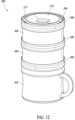
- FIG. 12 illustrates a modular storage system 300 .
- the modular storage system 300 is similar to the storage assembly 20 described herein, except as otherwise noted.
- the storage system 300 includes a cup 302 , a first bowl 304 , and a second bowl 306 and a plurality of lids 308 arranged in a stacked configuration, as described herein.
- Each of the lids 308 may be structurally identical and include a suction cup 310 extending from a top surface 309 of the lid 308 .
- the suction cup 310 is larger in diameter than the suction cups described with reference to assembly 20 . As shown in FIG.
- the suction cup 310 extends to a ridge 312 of each lid 308 , such that there is little or no aperture or gap between the suction cup 310 and the ridge 312 . More specifically, the suction cup 310 extends through aperture 152 described above with reference to bowl assembly 100 (see FIG. 3 ). As such, the suction cup 310 and part of the ridge 312 are a single, unitary, integral component, in some embodiments. Put another way, the suction cup 310 forms a sidewall of a channel for securing the lids 308 to the bowls 304 , 306 , and the cup 302 , or to other lids 308 .
- the larger size of the suction cup 310 increases the suction force to further secure the cup 302 or bowls 304 , 306 to an external surface, as described herein. More specifically, increasing a size of the suction cup 310 increases the volume of the vacuum of the suction cup 310 when the suction cup 310 is applied to a surface. The increased volume of vacuum increases the force required to unseat the suction cup 310 , or increases the suction force.
- FIG. 13 illustrates a bottom perspective view of one of the lids 308 and FIG. 14 is a cross-sectional view of one of the lids 308 .
- Each lid 308 includes a bottom surface 314 and a tower 316 extending from the bottom surface 314 .
- the tower 316 is cylindrical in shape and hollow, in some embodiments. Further, the tower 316 is centered with respect to, and forms part of the suction cup 310 , in one or more embodiments.
- the tower 316 increases the vacuum volume to further increase the suction force of suction cup 310 , among other advantages described herein.
- the tower 316 includes a bottom surface 318 with a depression or cavity 320 in the bottom surface 318 to give the tower 316 a concave appearance at the bottom surface 318 .
- FIG. 15 illustrates a cross-sectional view of the first bowl 304 .
- the second bowl 306 is similar to first bowl 304 , if not identical, in some embodiments, and as such, repetitive description has been omitted.
- the first bowl 304 has an internal cavity 322 with a volume that is the same as the volume described with respect to bowl assembly 100 (see FIGS. 2 and 3 ).
- a height 326 between a bottom 324 of the cavity 322 and a bottommost surface 328 of the first bowl 304 has been decreased in order to provide interaction with the tower 316 , as described below.
- the height 326 is between 3 and 4 mm less than the bowl assembly 100 .
- the decrease in height also allows the system 300 to take up less space in storage, while still retaining the same volume for storage of items.
- FIG. 16 is a cross-sectional view of the system 300 in the storage or stacked configuration.
- the tower 316 of a first one of the lids 308 extends into the cavity 322 of the first bowl 304 .
- the cup 302 includes a second lid 330 between the cup 302 and lid 308 , which may be similar to first lid 222 described herein with reference to cup assembly 200 .
- the tower 316 of the lid 308 attached to the cup 302 extends to deflect a flexible portion 332 of the second lid 330 .
- the flexible portion 332 is silicone, or some other flexible and resilient material, such that deflection of the flexible portion 332 does not create long term issues, such as permanent deformation of flexible portion 332 .
- the tower 316 of the lid 308 associated with the cup 302 extends into contact with, and extends at least partially through, the flexible portion 332 of second lid 330 , in some embodiments.
- FIGS. 17 A and 17 B are cross-sectional views of the cup 302 , lid 308 , and second lid 330 illustrating various use configurations.
- the user removes the lid 308 from the second lid 330 and inverts the lid 308 , such that the tower 316 faces a bottom 334 of the cup 302 .
- the bottom surface 314 of the lid 308 faces the cup 302
- the suction cup 310 and first surface 309 face an external surface.
- the geometry of the cup 302 and tower 316 are such that the tower 316 has a height that is greater than height 326 described with reference to FIG. 15 , which applies equally to cup 302 .
- the tower 316 is in contact with the bottom surface 334 of the cup 302 as the user attaches the cup 302 to the lid 308 .
- the user then presses the cup 302 down to secure the cup 302 to the lid 308 , as described herein and shown in more detail in FIG. 17 B .
- the bottom surface 334 of cup 302 contacts and acts on tower 316 , which is connected to suction cup 310 .
- the downward force flattens the suction cup 310 and secures the suction cup 310 to an external surface.
- the tower 316 engages the suction cup 310 to an external surface when the cup 302 (or one of the bowls 304 , 306 ) are assembled and then pressed onto a surface.
- the user can attach the lid 308 to the cup 302 prior to setting the cup 302 on a surface.
- the tower 316 activates the suction cup 310 to secure the cup 302 .
- the user can first set the lid 308 on a surface with the suction cup 310 facing the surface. Then, the user can attach the cup 302 to the lid 308 , which again, will activate suction cup 310 via tower 316 .
- applying the force to the cup 302 creates an additional suction force between cavity 320 in the tower 316 and the bottom surface 334 of the cup 302 , which further stabilizes the cup 302 .
- the same process described above for FIGS. 17 A and 17 B can be used to attach either of the bowls 304 , 306 to a surface, either with cup 302 in a stacked configuration, or separate and apart from cup 302 .
- the geometry of the system 300 allows for increased functionality of the lids 308 , the cup 302 , and bowls 304 , 306 .
- FIG. 18 is an exploded perspective view of an embodiment of a modular storage system 400 .
- the modular storage system 400 may be similar to any of the other systems described herein, except as otherwise explained below.
- the system 400 includes a first receptacle 402 , a first lid 404 , and a second lid 406 with the first and second lids 404 , 406 structured to be interchangeably coupleable to the first receptacle 402 and each other, as described herein.
- the first receptacle 402 may be a cup that includes an inside surface with volume or measurement indicators 408 . As shown in FIG. 18 , the first receptacle 402 may be a cup with an eight-ounce or one-cup capacity and the number and denomination of the indicators 408 may be selected according to design factors and the volume of the first receptacle 402 .
- FIG. 19 is a diametric cross-sectional view of the modular storage system 400 in an assembled, storage configuration.
- the second lid 406 is coupled to the first receptacle 402 and the first lid 404 is coupled to the second lid 406 to restrict access to the first receptacle 402 and minimize or prevent food or liquid from spilling out of the first receptacle 402 .
- the first receptacle 402 includes a body 410 with a first end 412 and a second end 414 opposite the first end 412 .
- the first end 412 may also be referred to herein as a first portion 412 , an upper end 412 , or a top end 412 of the body 410 .
- the second end 414 may also be referred to herein as a second portion 414 , a lower end 414 , or a bottom end 414 of the body 410 .
- the first and second lids 404 , 406 are coupled to the first end 412 of the body 410 of the receptacle 402 .
- the first receptacle 402 further includes a first cavity 416 (which may also be referred to herein as a first opening 416 ) in the first end 412 of the body 410 and a second cavity 418 (which may also be referred to herein as a second opening 416 ) in the second end 414 of the body 410 .
- the first and second cavities 416 , 418 are separated from each other by the body 410 , and specifically, by a bottom surface or bottom portion of the body 410 , as shown in FIG. 19 .
- the first cavity 416 is sized and shaped to receive one or more food items in solid or liquid form.
- the body 410 of the receptacle 402 further includes a first lip 420 at the first end 412 and a second lip 422 at the second end 414 .
- the first and second lips 420 , 422 extend around an entirety of the circumference of the first and second cavities 416 , 418 respectively. Further, the first and second lips 420 , 422 extend away from an outer surface of the body 410 and into the first and second cavities 416 , 418 , respectively.
- the lips 420 , 422 assist with the interchangeable coupling of the lids 404 , 406 to the receptacle 402 and can differ in shape from the other similar structures described herein.
- FIG. 20 is a detailed cross-sectional view of a connection between the receptacle 402 , the first lid 404 , and the second lid 406 .
- FIG. 20 is a detail view of area B indicated with dashed lines in FIG. 19 .
- the first lip 420 includes a first surface 424 A and a second surface 424 B opposite the first surface 424 A.
- the first surface 424 A is flat and planar and extends horizontally and perpendicularly to the first end 412 of the first receptacle 402 in some embodiments.
- the second surface 424 B is at least partially or continuously curved or rounded in some embodiments to reduce the risk of harm from sharp edges.
- the first surface 424 A forms a ledge or ridge to assist with coupling the first end 412 of the receptacle 402 to the first lid 404 or the second lid 406 .
- the second lid 406 may include a similar structure 426 as the first lip 420 for coupling to the first lid 404 .
- the first and second lids 404 , 406 may include channels that have a corresponding size and shape for receiving the first lip 420 , as described with reference to FIG. 21 .
- the second lip 422 shown in FIG. 19 may be a mirror image of the first lip 420 .
- the first and second lips 420 , 422 have different shapes or structures that are selected to facilitate coupling to one or more lids or for frictional or physical engagement with one or more lids.
- FIG. 21 is a diametric cross-sectional view of the first lid 404 of the modular storage system 400 .
- the first lid 404 includes a suction cup 428 with a first or flat portion 430 and a second or angled portion 432 coupled to and integral with the flat portion 430 as a single, unitary component.
- the angled portion 432 extends radially outward and vertically away from the flat portion 430 . In other words, the angled portion 432 extends continuously from the flat portion 430 at a selected transverse angle that may be between 0 and 90 degrees to horizontal in some embodiments.
- the suction cup 428 further includes a base 434 integral with the suction cup 428 as a single, unitary component.
- the base 434 provides support for the suction cup 428 and is also structured to contact the second end 414 of the body 410 of the first receptacle 402 (see FIG. 24 ) in order to engage the suction cup 428 to a support surface when the first lid 404 is coupled to the receptacle 402 .
- the first lid 404 has a first surface 436 and a second surface 438 opposite the first surface 436 .
- the first and second surfaces 436 , 438 are top and bottom outermost surfaces of the first lid 404 with a height 440 of the first lid 404 extending from the first surface 436 to the second surface 438 .
- the suction cup 428 has an outermost peripheral edge 442 and a height 444 from a bottom of the base 434 to the outermost peripheral edge 442 that is greater than the height 440 of the first lid 404 .
- the outermost peripheral edge 442 extends beyond a horizontal plane represented by dashed line C that includes an upper surface, such as first surface 436 , of the first lid 404 .
- the height of the suction cup 428 relative to the first lid 404 assists with engaging the suction cup 428 to a support surface when the first lid 404 is coupled to the bottom of a receptacle, as explained further herein.
- the height 440 of the first lid 404 is equal to or greater than the height 444 of the suction cup 428 and base 434 .
- the first lid 404 further includes a first channel 446 in the first surface 436 of the first lid 404 that is structured to receive the first lip 420 and the second lip 422 ( FIG. 19 ) of the first lid 404 to facilitate the interchangeable coupling of the first lid 404 to the body 410 of the first receptacle 402 ( FIG. 19 ).
- the first channel 446 extends around at least part of, or all of, the first lid 404 in some embodiments.
- the first lid 404 also includes a second channel 448 in the second surface that is aligned with the first channel and is a mirror image of the first channel 446 .
- the second channel 448 is structured to receive the lip of an additional receptacle in a stacking arrangement, as shown in FIG. 26 .
- a third channel 450 extends into the first surface 436 of the first lid 404 around the suction cup 428 to provide the suction cup 428 with space to expand and contract during attachment to a support surface.
- the third channel 450 is positioned closer to the suction cup 428 and a center of the first lid 404 than the first channel 446 and the second channel 448 .
- FIG. 22 is a perspective bottom view of the first lid 404 of the modular storage system 400 .
- the base 434 of the suction cup 428 includes a cavity 452 , which can reduce the material cost of the first lid 404 .
- the base 434 of the suction cup 428 ( FIG. 21 ) also extends from the bottom of the first lid 404 to assist with engaging the suction cup 428 to a support surface through contact of the base 434 of the suction cup 428 with the bottom of a receptacle.
- FIG. 23 is a perspective view of an embodiment of a modular storage system 500 A including a receptacle 502 A, a first lid 504 A, and a second lid 506 A.
- the first receptacle 502 A and the second lid 506 A may be identical to the receptacle 402 and the first lid 404 of the system 400 described with reference to FIGS. 18 - 22 , in some embodiments.
- the first lid 504 A is configured to be coupled to the receptacle 502 A and includes a protrusion 508 A extending from a top surface 510 A of the first lid 504 A.
- the first lid 504 A is also structured to receive the second lid 506 A in a stacked arrangement to seal the first lid 504 A. As shown in FIG.
- the protrusion 508 A is structured to receive a straw 512 A, such that the first lid 504 A and receptacle 502 A are operable as a “sippy cup” and the second lid 506 A is operable to seal the first lid 504 A to minimize or prevent liquid from escaping through the protrusion 508 A, as further described herein.
- FIG. 24 A is a diametric cross-sectional view of the modular storage system 500 A showing features of the system 500 A in additional detail.
- the protrusion 508 A of the first lid 504 A has an axial bore 514 A through the protrusion 508 A.
- the axial bore 514 A is sized and shaped to receive the straw 512 A with sidewalls of the protrusion 508 A in abutting contact or frictional engagement with the straw 512 A.
- the sidewalls of the protrusion 508 A form a liquid tight seal or substantially liquid tight seal with the straw 512 A such that minimal, if any, liquid will escape the receptacle 502 A if the system 500 A tips over.
- substantially liquid tight seal refers to a volume of liquid escaping through the protrusion 508 A over a selected period of time, wherein the volume of liquid may be 16, 15, 14, 13, 12, 11, 10, 9, 8, 7, 6, 5, 4, 3, 2, 1 or fewer ounces that escape through the protrusion 508 A with the straw 512 A inserted over a period of time of one minute, 45 seconds, 30 seconds, 15 seconds, 10 seconds, 5 seconds, or less when the system 500 A is horizontal or on its side on a support surface.
- the second lid 506 A of the system 500 A includes a suction cup 516 A that is structured to be coupled to the receptacle 502 A and to engage a support surface to prevent the system 500 A from tipping over, which also reduces the likelihood of liquid spilling from the receptacle 502 A to the support surface via the protrusion 508 A and axial bore 514 A.
- the sidewalls of the protrusion 508 A are tapered along at least a portion of, or all of, the height of the protrusion 508 A such that a diameter of the axial bore 514 A is greater proximate the top surface 510 A of the first lid 504 A than a diameter of the bore 514 A at an outer or outermost peripheral edge 518 A of the protrusion 508 A.
- the tapered sidewalls of the protrusion 512 A can assist with engaging the straw 512 A while also enabling some angular or side-to-side movement of the straw 512 A relative to the receptacle 502 A.
- the straw 512 A can include a protrusion 520 A projecting from the straw 512 A to resist or prevent the straw 512 A from sliding completely through the axial bore 514 A of the protrusion 508 A of the first lid 504 A.
- the protrusion 520 A of the straw 512 A may also be referred to herein as a ledge, flange, stopper, or ridge 520 A.
- the protrusion 520 A of the straw 512 A is annular and extends outward from a sidewall 513 A of the straw 512 A around an entirety of the circumference of the straw 512 A.
- the protrusion 520 A extends from only a portion of the circumference of the straw and may include more than one protrusion 520 A spaced about the straw 512 A. In some embodiments, the protrusion 520 A is located on a lower half or upper half of the straw 512 A and is positioned closer to a top or bottom of the straw 512 A than a center of the straw 512 A.
- the first lid 504 A further includes a lip 522 A that may be similar to lip 420 to facilitate interchangeable coupling of the second lid 506 A to the first lid 504 A, or other similar articles in a stacking arrangement.
- the lip 522 A of the first lid 504 A also defines an outer or outermost peripheral surface 524 A of the first lid 504 A.
- the protrusion 508 A of the first lid 504 A extends beyond a plane indicated by dashed line D that includes the outer or outermost peripheral surface 524 A of the first lid 504 A to allow the user to more easily access the protrusion 508 A (i.e., to more easily place their mouth on the protrusion 508 A).
- 506 A is an outer or outermost peripheral surface 524 A of the first lid 504 A to allow the user to more easily access the protrusion 508 A (i.e., to more easily place their mouth on the protrusion 508 A).
- the suction cup 516 A of the second lid 506 A includes a base 526 A that contacts a bottom 528 A (which may also be referred to herein as a bottom portion 528 A or a portion 528 A) of the receptacle 502 A to engage the suction cup 516 A to a support surface.
- the suction cup 516 A and base 526 A have a height that is greater than a depth of the cavity below the bottom 528 A of the receptacle 502 A.
- the suction cup 516 A is structured to automatically contact and engage a support surface during coupling of the various components described herein.
- the user can couple the second lid 506 A to the receptacle 502 A first, and then press the assembly onto the support surface, with the bottom 528 A of the receptacle 502 A again contacting the second lid 506 A and assisting with securing the suction cup 516 A to the support surface.
- FIG. 24 B is a diametric cross-sectional view of the modular storage system of FIG. 23 in a storage configuration.
- the second lid 506 A is coupled to the first lid 504 A with the protrusion 508 A in abutting contact with the second lid 506 A 0 .
- the straw 512 A is removed prior to coupling the second lid 506 A to the first lid 504 A, and can be reinserted through a bottom of the first lid 504 A in the use configuration shown in FIG. 23 and FIG. 24 A .
- the second lid 506 A includes an elastic or flexible material, such as food grade silicone, with a wall thickness that is less than a wall thickness of the second lid 506 A and the protrusion 508 A has a height greater than a depth of a cavity between the first lid 504 A and the second lid 506 A.
- an elastic or flexible material such as food grade silicone
- the second lid 506 A may deform the protrusion 508 A by expanding a diameter of the protrusion 508 A, in which case the second lid 506 A is in abutting contact with the protrusion 508 A and further seals the axial bore 514 A.
- the protrusion 508 A may have a greater wall thickness than the second lid 506 A and will deform a web of the second lid 506 A.
- FIGS. 25 - 31 are various views of an additional embodiment of the modular storage system 500 B.
- the modular system 500 B is the same as system 500 A, except as otherwise described below.
- the system 500 B includes a receptacle 502 B and a first lid 504 B coupled to the receptacle 502 B.
- the first lid 504 B is configured to receive a straw 506 B and includes an air hole 508 B through the lid 504 B to prevent formation of a vacuum in the receptacle 502 B during use.
- FIG. 26 is a perspective view of the straw 506 B which includes a sidewall 510 B and a stopper 512 B extending from the sidewall 510 B of the straw 506 B.
- the stopper 512 B is positioned proximate a center of the straw 506 B relative to its height in order to prevent a user from pulling the straw 506 B out of the first lid 504 B (see FIG. 28 ).
- the position of the stopper 512 B relative to the straw 506 B can be selected according to design factors.
- the straw 506 B includes at least one groove 514 B extending into the sidewall 510 B of the straw 506 B.
- the at least one groove 514 B is a channel extending in a longitudinal direction of the straw 506 B and allows for air flow around the straw 506 B when the straw 506 B is inserted into the first lid 504 B. As shown in FIG.
- the grooves 516 B there are a plurality of grooves 516 B spaced equidistant from each other about a diameter of the straw 506 B with the grooves 516 B generally arranged in a vertical direction in the orientation shown in FIG. 26 .
- the characteristics of the grooves 516 B can also be selected, such that the spacing, size, number, and orientation of the grooves 516 B may be different in some embodiments.
- the at least one groove 516 B also extends across the stopper 512 B such that the stopper 512 B does not restrict airflow during use.
- FIG. 27 is a top plan view of the first lid 504 B that illustrates that the lid 504 B includes a membrane 518 B extending across an opening 520 B of a protrusion 522 B extending from the first lid 504 B and structured to receive the straw 506 B.
- the membrane 518 B may be a layer of elastic and flexible material, such as food grade silicone with a thickness and position relative to the protrusion 522 B that is selected according to design factors.
- the membrane 518 B prevents or restricts liquid from spilling out of the receptacle 502 B if the receptacle 502 B is tipped or knocked over.
- the membrane 518 B includes at least one slit 524 B such that liquid can be dispensed through the opening 520 B when pressure is applied to the membrane 518 B, such as negative pressuring from sucking on the protrusion 522 B during normal use.
- the at least one slit 524 B includes two slits 524 B that are perpendicular to each other in an “X” shape although other numbers of slits 524 B and arrangements of the slits 524 B are contemplated herein, such as a single slit 524 B across the membrane 518 B in one non-limiting example.
- the first lid 504 B can be used without the straw 506 B as a “sippy” lid with the membrane 518 B preventing liquid from spilling or slowing a rate of liquid spills and the slit 524 B allowing for liquid to pass through opening 520 B under pressure during use.
- FIG. 28 is a diametric cross-sectional view of the system 500 B.
- the user removes the first lid 504 B inserts the straw 506 B through a bottom of the protrusion 522 B and through the opening 520 B ( FIG. 27 ). Then, the user couples the first lid 504 B with the straw 506 B to the receptacle 502 B. As shown in FIG. 28 , the straw 506 B passes through the membrane 518 B and via the slits 524 B ( FIG. 27 ) and deflects the membrane 518 B toward the protrusion 522 B.
- the stopper 512 B is positioned proximate to, but below a base or bottom of the protrusion 522 B to prevent the stopper 512 B from restricting airflow via the grooves 516 B and to also limit a range of motion of the straw 506 B.
- the stopper 512 B is proximate to, but does not contact (i.e., is spaced from) the protrusion 522 B to prevent a user from pulling up on the straw 506 B while also allowing air to flow through the protrusion 522 B via the grooves 516 B.
- the straw 506 B can be removed by reversing the steps above and the first lid 504 B can be used as a sippy cup lid, as described above.
- FIG. 29 is a detail view of a portion of the first lid 504 B showing the air hole 508 B in additional detail.
- the air hole 508 B extends completely through a web of the first lid 504 B from a first surface of the web to a second surface of the web to allow air to pass through the air hole 508 B and prevent a vacuum from forming in the receptacle 502 B during use.
- the air hole 508 B has a small diameter in some embodiments to reduce the amount of liquid that passes through the air hole 508 B if the system 500 B is knocked or tipped over.
- the air hole 508 B is positioned proximate an outer peripheral edge of the first lid 504 B in some embodiments, although the size and the position of the air hole 508 B can be selected to be different in some embodiments according to design factors.
- FIG. 30 is a top perspective view of a second lid 526 B that is structured to be coupled to the receptacle 502 B and the first lid 504 B in a stacking arrangement, as described herein.
- the second lid 526 B has a channel 528 B around a suction cup 530 B.
- the straw 506 B is formed from a flexible and elastic material, such as food grade silicone, and has a size and a shape to be received in the channel 528 B.
- the straw 506 B can be bent and coupled to the second lid 526 B with the straw 506 B received within the channel 528 B for storage when the straw 506 B is not in use.
- the second lid 526 B can be coupled to the first lid 504 B (see FIG.
- the second lid 526 B deforms the protrusion 522 B and may cause the membrane 518 B to open slightly.
- the coupling between the first lid 504 B and the second lid 526 B acts as a second seal (between the lids 504 B, 526 B or between the second lid 526 B and the top of the protrusion 522 B, or both) that prevents liquid from spilling.
- the coupling of the second lid 526 B to the first lid 504 B prevents liquid from escaping that may pass through air hole 508 B.
- the second lid 526 B seals the first lid 504 B in the storage configuration with the second lid 526 B also receiving and storing the straw 506 B in the channel 528 B.
- FIG. 31 is a bottom perspective view of the modular storage system 500 B.
- FIG. 31 illustrates a bottom surface 532 B of the receptacle 502 B wherein the bottom surface 532 B includes at least one channel 534 B extending into the bottom surface 532 B.
- the at least one channel 534 B prevents the suction cups described herein from sticking to the bottom of the receptacle 502 B in the stacked arrangement (see FIG. 35 ).
- the number, size, and arrangement of the at least one channel 534 B can be selected.
- FIG. 31 illustrates a bottom surface 532 B of the receptacle 502 B wherein the bottom surface 532 B includes at least one channel 534 B extending into the bottom surface 532 B.
- the at least one channel 534 B prevents the suction cups described herein from sticking to the
- channels 534 B other structures are contemplated herein for preventing the suction cup from coupling to the bottom surface 532 B, such as protrusions, ledges, ridges, apertures, cavities, and other like structures.
- the channels 534 B increase the ease of use of the system 500 B and allow the modular storage system 500 B to be separated more easily from other storage systems while keeping the lids, such as second lid 526 B, coupled to the receptacles 502 B.
- FIG. 32 is a perspective view of an embodiment of a modular storage system 600 including a first receptacle 602 , a second receptacle 604 , a first lid 606 , a second lid 608 , and a third lid 610 coupled together in a space-saving stacked arrangement.
- FIG. 33 is a diametric cross-sectional view of the modular storage system 600 shown in FIG. 32 .
- the first receptacle 602 may be similar to receptacle 402 ( FIG. 19 )
- the first lid 606 may be similar to lid 406 ( FIG. 18 )
- the second lid 608 may be similar to lid 504 A ( FIG.
- FIG. 24 A and the third lid 610 may be similar to lid 404 ( FIG. 21 ).
- FIG. 32 and FIG. 33 are provided to show the interchangeable coupling of the various components described herein as well as features of the second receptacle 604 .
- the second receptacle 604 has a lip 612 that is structured to be received in a first channel 614 of the third lid 610 .
- the first channel 614 of the third lid 610 has a size and a shape to frictionally engage the lip 612 of the second receptacle 604 .
- the third lid 610 also has a second channel 616 that is a mirror image of the first channel 614 and is structured to receive a lip 618 of the first receptacle 602 .
- FIG. 32 and FIG. 33 illustrate that the first lid 606 , which may include one or more slits, can be stacked with other lids described herein, such as the second lid 608 or the third lid 610 .
- the second receptacle 604 can be the same as, or different than, the first receptacle 602 .
- the second receptacle 604 may be a bowl without a handle and having a smaller volume than the first receptacle 602 .
- FIG. 34 is a perspective view of an embodiment of a modular storage system 700 including a first receptacle 702 , a second receptacle 704 , a first lid 706 , and a second lid 708 coupled together in a stacked arrangement.
- FIG. 35 is a diametric cross-sectional view of the modular storage system 700 shown in FIG. 34 .
- FIG. 34 and FIG. 35 illustrate an additional arrangement of the lids 706 , 708 in the stacked arrangement relative to other embodiments described herein.
- the second lid 708 can be arranged in the stacked arrangement with a suction cup 710 of the second lid 708 facing the first receptacle 702 .
- the suction cup 710 may secure, at least partially, to the first receptacle 702 to provide a stronger coupling between the components of the system 700 in the stacked arrangement.
- each of the receptacles 702 , 704 shown in FIG. 34 and FIG. 35 are bowls.
- the system 700 can include any selected number or type of bowls, cups, or lids described herein coupled to each other in a stacked arrangement and in a selected orientation due to the modular nature of the components.
- FIG. 36 is a perspective view of an embodiment of a modular storage system 800 including a first receptacle 802 and a first lid 804 coupled to the first receptacle 802 .
- the first receptacle 802 may be a plate and while the first lid 804 may share some similar aspects with the other lids described herein, the size and shape of the first lid 804 corresponds to the size and shape of the plate. As such, the first lid 804 may be larger than the lids of the other storage systems described herein, in one or more embodiments.
- FIG. 37 is a perspective exploded view of the modular storage system 800 and FIG. 38 is a top plan view of the first receptacle 802 .
- the first receptacle 802 includes a first surface 806 and a first opening 808 in the first surface 806 .
- the first receptacle 802 includes a divider 810 (which may also be referred to herein as a sidewall or a plurality of sidewalls 810 ) that separates an interior of the first receptacle 802 and the first opening 808 into a plurality of cavities 812 A, 812 B, 812 C, 812 D each having a selected volume.
- the fourth cavity 812 D is arranged centrally relative to the first receptacle 802 and the first, second, and third cavities 812 A, 812 B, 812 C are positioned around the fourth cavity 812 D with the first cavity 812 A on an opposite side of the receptacle 802 from the second and third cavities 812 B, 812 C.
- the first cavity 812 A has a volume of eight ounces
- each of the second and third cavities 812 B, 812 C has a volume of four ounces
- the fourth cavity 812 D has a volume of one ounce, although the same is not necessarily required as the cavities 812 A, 812 B, 812 C, 812 D can be selected to have any volume, number, and arrangement.
- the different cavities 812 A, 812 B, 812 C, 812 D can be used to organize and store different food materials in different quantities.
- FIG. 37 and FIG. 38 illustrate that the divider 810 has angled, sloped, curved, rounded, or tapered sidewalls along its height.
- the divider 810 is angled, sloped, curved, rounded, or tapered along at least a first portion of the divider 810 from a bottom surface of each cavity 812 A, 812 B, 812 C, 812 D to an outer or outermost peripheral edge or surface of the divider 810 that is connected to and integral with a second vertical portion.
- the shape of the divider 810 can assist young children with grasping food items in the cavities 812 A, 812 B, 812 C, 812 D.
- FIG. 39 A is a diametric cross-sectional view of the modular storage system 800 with the first lid 804 in a storage configuration
- FIG. 39 B is a diametric cross-sectional view of the system 800 with the first lid 804 in a use configuration and secured to a support surface.
- the first receptacle 802 has a first portion 814 and a second portion 816 wherein the first portion 814 may be an upper portion and the second portion 816 may be a lower portion.
- the first lid 804 is coupled to the first portion 814 of the receptacle 802 in the storage configuration.
- the first lid 804 includes a lip or ridge 818 that extends from a bottom surface of the first lid 804 in frictional engagement with the divider 810 around the fourth cavity 812 D to seal the fourth cavity 812 D and minimize or prevent food or liquid from escaping the fourth cavity 812 D during storage or transport.
- the lip 818 may be annular and extend around an entirety of the fourth cavity 812 D to provide a liquid tight seal between the first lid 804 and the fourth cavity 812 D in some embodiments.
- the receptacle 802 further includes a second surface 807 opposite to the first surface 806 and a second opening 809 in the second portion 816 opposite the first opening 808 .
- the first lid 804 also includes opposing channels 820 , 822 wherein each channel has a lip 824 (which may also be referred to herein as a flange, ridge, or protrusion 824 ) extending into the respective channel 820 , 822 to engage a correspondingly shaped lip 826 of the first receptacle 802 to form a seal, which may be a liquid tight seal, between the first lid 804 and the first, second, and third cavities 812 A, 812 B, 812 C ( FIG. 38 ).
- FIG. 39 A also shows additional detail of the first opening 808 in the first surface 806 of the receptacle 802 and in particular, that the first lid 804 covers the first opening 808 in the storage configuration in FIG. 39 A to selectively provide access to the first opening 808 .
- the first lid 804 is removed to provide access to the first opening 808 and is inverted and coupled to the second portion 816 of the first receptacle 802 in a use configuration.
- the channel 822 and lip 824 of the first lid 804 receive the lip 828 of second portion 816 of the receptacle 802 in a frictional engagement to secure the first lid 804 to the second portion 816 of the receptacle 802 .
- the first lid 804 is coupled to the second surface 807 of the receptacle 802 and restricts access to the second opening 809 .
- at least a portion of the first lid 804 is received in the second opening 809 in the use configuration.
- the lip 818 of the first lid 804 is received in a cavity 811 in the divider 810 that is connected to the second opening 809 and extends around a bottom of the fourth cavity 812 D.
- the first lid 804 further includes a suction cup 830 that may be similar to the other suction cups described herein, except that the suction cup 830 does not have a cavity in its base and does not necessarily have the same base structure as the other suction cups due to differences in size.
- the suction cup 830 has a base 832 that is flat and planar in some embodiments with a cavity 834 in the suction cup 830 instead of in the base 832 to improve the adhesion properties of the suction cup 830 relative to a support surface.
- the first receptacle 802 and the first lid 804 have a size and shape to be interchangeably coupled to the cups, bowls, and lids described herein.
- the first receptacle 802 and first lid 804 are not interchangeably coupleable with the other structures described herein because of their increased size. However, the first receptacle and first lid 804 are interchangeably coupleable in a stacked arrangement with other similarly sized receptacles and lids.
- FIG. 40 is a diametric cross-sectional view of the system 800 with the first receptacle 802 and the first lid 804 coupled to a second receptacle 836 and a second lid 838 in a stacked arrangement.
- the second receptacle 836 and the second lid 838 may be similar to the first receptacle 802 and the first lid 804 , respectively, such that the second lid 838 is adapted to receive the first and second receptacles 802 , 836 in the space saving stacked arrangement shown in FIG. 40 in a similar manner to other systems described herein.
- the systems, devices, and methods described herein provide a modular storage system with bowls, cups, plates, and lids that have a space saving, stackable design.
- the component parts can be configured in a number of different use configurations to prevent spilling of the materials stored in the system.
- the dual functionality of certain component parts, such as the lids described herein, improves the functionality and efficiency of the design over known storage systems.
Abstract
Description
Claims (20)
Priority Applications (2)
| Application Number | Priority Date | Filing Date | Title |
|---|---|---|---|
| US17/236,511 US11596250B2 (en) | 2020-06-15 | 2021-04-21 | Modular storage system |
| CN202121322977.7U CN216494684U (en) | 2020-06-15 | 2021-06-15 | Modular storage system |
Applications Claiming Priority (2)
| Application Number | Priority Date | Filing Date | Title |
|---|---|---|---|
| US202063039353P | 2020-06-15 | 2020-06-15 | |
| US17/236,511 US11596250B2 (en) | 2020-06-15 | 2021-04-21 | Modular storage system |
Publications (2)
| Publication Number | Publication Date |
|---|---|
| US20210386227A1 US20210386227A1 (en) | 2021-12-16 |
| US11596250B2 true US11596250B2 (en) | 2023-03-07 |
Family
ID=78824152
Family Applications (1)
| Application Number | Title | Priority Date | Filing Date |
|---|---|---|---|
| US17/236,511 Active US11596250B2 (en) | 2020-06-15 | 2021-04-21 | Modular storage system |
Country Status (3)
| Country | Link |
|---|---|
| US (1) | US11596250B2 (en) |
| CN (1) | CN216494684U (en) |
| WO (1) | WO2021257175A1 (en) |
Families Citing this family (2)
| Publication number | Priority date | Publication date | Assignee | Title |
|---|---|---|---|---|
| USD1003111S1 (en) * | 2020-12-08 | 2023-10-31 | Feng Liu | Silicone cup |
| WO2023009556A1 (en) * | 2021-07-27 | 2023-02-02 | Quinonez Richard | Multi-chambered shot glass |
Citations (55)
| Publication number | Priority date | Publication date | Assignee | Title |
|---|---|---|---|---|
| US1892140A (en) | 1929-12-02 | 1932-12-27 | Arthur S Fogler | Collapsible container |
| US3091361A (en) * | 1961-03-06 | 1963-05-28 | Paul F Gawron | Containers |
| US4091953A (en) * | 1975-09-10 | 1978-05-30 | Dart Industries Inc. | Multi-purpose bowl set |
| US4143785A (en) * | 1978-03-16 | 1979-03-13 | Sun Coast Plastic Closures, Inc. | Plastic vacuum sealing cap |
| US4869381A (en) | 1988-05-06 | 1989-09-26 | Agner Ann H | Infant feeder and support therefor |
| US4955493A (en) * | 1989-08-15 | 1990-09-11 | Touzani William N | Collapsible expansible plastic hollow articles in a latchable configuration |
| US5255816A (en) * | 1992-12-21 | 1993-10-26 | Trepp Charles A | Article storing apparatus |
| US5273182A (en) * | 1991-10-09 | 1993-12-28 | Laybourne Sidney C | Coaster |
| US5409126A (en) * | 1993-10-13 | 1995-04-25 | Demars; Robert A. | Storage container with reversible lid |
| US5570797A (en) * | 1995-03-06 | 1996-11-05 | Yeh; Frank | Mug and multipurpose lid combination |
| US5775483A (en) * | 1997-01-09 | 1998-07-07 | Flotool Plastics Corporation | Stackable containers with removable cover members |
| US20010022304A1 (en) * | 1999-09-16 | 2001-09-20 | Howard Roche | Container |
| US20020134789A1 (en) * | 2001-01-19 | 2002-09-26 | Shin-Shuoh Lin | Coffee mug with interchangeable accessories |
| US20030155363A1 (en) * | 2002-02-15 | 2003-08-21 | Doug Mercier | Nesting containers and lids |
| US20040069677A1 (en) * | 2002-08-23 | 2004-04-15 | L'oreal | Container with removable protective element |
| US6814250B1 (en) * | 2003-05-12 | 2004-11-09 | Jon W. Madsen | Food serving system |
| US20050072709A1 (en) * | 2002-10-17 | 2005-04-07 | Mann John David | Method and apparatus for stacking cans |
| US20050252923A1 (en) | 2004-05-13 | 2005-11-17 | Woolf Mary P | Spill proof container for non-liquid materials |
| US20060151511A1 (en) * | 2005-01-07 | 2006-07-13 | Progressive International Corp. | Suction cup lid |
| US20070029325A1 (en) * | 2004-11-28 | 2007-02-08 | Consolidated Container Company Lp | Covered containers and related dispensing systems |
| US20070029333A1 (en) * | 2005-08-08 | 2007-02-08 | Dua Gregory C | Bowl with a base layer and a lid as a base |
| US7357273B1 (en) * | 2005-01-19 | 2008-04-15 | Lutz Trent L | Container unit |
| US20090078712A1 (en) * | 2007-09-22 | 2009-03-26 | Israel Harry Zimmerman | Self-anchoring beverage container with directional release and attachment capability |
| US7510096B2 (en) * | 2003-04-09 | 2009-03-31 | Korea Alphaline Co., Ltd. | Multi-layered container with intermediate lid |
| US8002140B2 (en) | 2005-08-18 | 2011-08-23 | Baby Dipper Llc | Baby bowl |
| US20110284537A1 (en) * | 2010-05-18 | 2011-11-24 | M & N Plastics, Inc. | Pastry cradle and cradle/lid combination |
| US20110290815A1 (en) * | 2008-12-18 | 2011-12-01 | Spillip Pty Ltd | Device for sealing a container |
| US8302798B2 (en) | 2001-09-04 | 2012-11-06 | Moss Christine K | Anti-spill container |
| USD675067S1 (en) | 2011-04-15 | 2013-01-29 | Playtex Products, Llc | Container |
| US20130248537A1 (en) * | 2012-03-22 | 2013-09-26 | Thermos L.L.C. | Food transport and storage container having removable inner container and insulating outer sleeve |
| US20130320164A1 (en) * | 2012-05-29 | 2013-12-05 | Munchkin, Inc. | Double acting suction cup |
| US8757426B1 (en) * | 2012-11-05 | 2014-06-24 | German J. Serrano | Beverage container with integrated anchoring system |
| US20140284342A1 (en) * | 2013-03-12 | 2014-09-25 | Hewy Wine Chillers, LLC | Insulated beverage apparatus and cooling device |
| US8985363B2 (en) | 2012-09-10 | 2015-03-24 | Mattel, Inc. | Food/drink container |
| US20150114963A1 (en) * | 2014-12-11 | 2015-04-30 | Ronald J. Billett | Combination Beverage Cup and Lid or Base |
| US20150114964A1 (en) * | 2012-03-26 | 2015-04-30 | Gateway Plastics, Inc. | Closure for a container |
| US20150353241A1 (en) * | 2014-06-06 | 2015-12-10 | Fisher Scientific Company L.L.C. | Tamper-Evident Closure Assembly Including Outer Shell, And Related Systems And Methods |
| US20160000271A1 (en) * | 2013-02-22 | 2016-01-07 | Boru International Co., Ltd. | Container lid for vacuum sealing having locking parts and vacuum-sealed container employing same |
| US20160009465A1 (en) * | 2014-07-10 | 2016-01-14 | Wei-Chih Pan | Cup lid and container with cup lid |
| USD751391S1 (en) | 2014-05-13 | 2016-03-15 | Sienna Group Corporation | Retaining piece for drinking bottle |
| USD751392S1 (en) | 2014-05-13 | 2016-03-15 | Sienna Group Corporation | Retaining piece for drinking bottle |
| US20160075484A1 (en) * | 2014-09-16 | 2016-03-17 | Rieke Corporation | Closure for a container lid |
| US9399297B2 (en) * | 2013-05-24 | 2016-07-26 | Vtec Co., Ltd. | Pad-separable suction cup |
| US20170225843A1 (en) * | 2014-06-06 | 2017-08-10 | Fisher Scientific Company, L.L.C. | Tamper-Evident Closure Assembly Including Outer Shell, And Related Systems And Methods |
| US20170238737A1 (en) * | 2016-01-26 | 2017-08-24 | Munchkin, Inc. | Bowl assembly with masher |
| US9801483B2 (en) * | 2014-05-28 | 2017-10-31 | Binky Enterprises, LLC | Adjustable beverage holder |
| CN107468004A (en) | 2017-09-26 | 2017-12-15 | 无锡市特殊教育学校 | It is a kind of can overturning-preventing pupil's bowl |
| US10053277B2 (en) * | 2015-06-16 | 2018-08-21 | Boehringer Ingelheim Vetmedica Gmbh | Connecting and container system |
| US20180312306A1 (en) * | 2017-04-27 | 2018-11-01 | Enhance Product Development, Inc. | Storage container lid system with attachment device |
| US20190069703A1 (en) | 2017-09-01 | 2019-03-07 | Brooke Boak | Non-slip container with hidden suction cup |
| US20190300236A1 (en) * | 2016-05-23 | 2019-10-03 | Å&R Carton Lund Aktiebolag | Packaging container with stacking members |
| US20210007522A1 (en) * | 2019-07-12 | 2021-01-14 | Brandon Stuart | Surface suctioning receptacle for container |
| US11001423B2 (en) * | 2018-12-07 | 2021-05-11 | The Yankee Candle Company, Inc. | Container vessel with pedestal lid |
| US20210137322A1 (en) * | 2019-11-12 | 2021-05-13 | Gojo Industries, Inc. | Wipes dispensing canisters and wipes dispensing casnister mounting brackets |
| US11021296B2 (en) * | 2012-08-31 | 2021-06-01 | Wilshire Industries, Llc | Collapsible food container |
Family Cites Families (5)
| Publication number | Priority date | Publication date | Assignee | Title |
|---|---|---|---|---|
| IT1247672B (en) * | 1990-01-25 | 1994-12-28 | Olimpio Stocchiero | COVER WITH SEALING DEVICE FOR CONTAINERS |
| US5000123A (en) * | 1990-04-04 | 1991-03-19 | Morse Diana J | Animal food dish construction |
| US8967416B2 (en) * | 2009-01-09 | 2015-03-03 | Rubbermaid Incorporated | Food storage container and container system |
| US20140326630A1 (en) * | 2013-05-06 | 2014-11-06 | A2 Product Development, Inc. | Stackable serving vessel |
| US9150330B1 (en) * | 2013-08-21 | 2015-10-06 | David M Stravitz | Multi-compartment vessel with optional lids |
-
2021
- 2021-04-21 WO PCT/US2021/028374 patent/WO2021257175A1/en active Application Filing
- 2021-04-21 US US17/236,511 patent/US11596250B2/en active Active
- 2021-06-15 CN CN202121322977.7U patent/CN216494684U/en active Active
Patent Citations (61)
| Publication number | Priority date | Publication date | Assignee | Title |
|---|---|---|---|---|
| US1892140A (en) | 1929-12-02 | 1932-12-27 | Arthur S Fogler | Collapsible container |
| US3091361A (en) * | 1961-03-06 | 1963-05-28 | Paul F Gawron | Containers |
| US4091953A (en) * | 1975-09-10 | 1978-05-30 | Dart Industries Inc. | Multi-purpose bowl set |
| US4143785A (en) * | 1978-03-16 | 1979-03-13 | Sun Coast Plastic Closures, Inc. | Plastic vacuum sealing cap |
| US4869381A (en) | 1988-05-06 | 1989-09-26 | Agner Ann H | Infant feeder and support therefor |
| US4955493A (en) * | 1989-08-15 | 1990-09-11 | Touzani William N | Collapsible expansible plastic hollow articles in a latchable configuration |
| US5273182A (en) * | 1991-10-09 | 1993-12-28 | Laybourne Sidney C | Coaster |
| US5255816A (en) * | 1992-12-21 | 1993-10-26 | Trepp Charles A | Article storing apparatus |
| US5409126A (en) * | 1993-10-13 | 1995-04-25 | Demars; Robert A. | Storage container with reversible lid |
| US5570797A (en) * | 1995-03-06 | 1996-11-05 | Yeh; Frank | Mug and multipurpose lid combination |
| US5775483A (en) * | 1997-01-09 | 1998-07-07 | Flotool Plastics Corporation | Stackable containers with removable cover members |
| US20010022304A1 (en) * | 1999-09-16 | 2001-09-20 | Howard Roche | Container |
| US20020134789A1 (en) * | 2001-01-19 | 2002-09-26 | Shin-Shuoh Lin | Coffee mug with interchangeable accessories |
| US8302798B2 (en) | 2001-09-04 | 2012-11-06 | Moss Christine K | Anti-spill container |
| US20030155363A1 (en) * | 2002-02-15 | 2003-08-21 | Doug Mercier | Nesting containers and lids |
| US20040069677A1 (en) * | 2002-08-23 | 2004-04-15 | L'oreal | Container with removable protective element |
| US20050072709A1 (en) * | 2002-10-17 | 2005-04-07 | Mann John David | Method and apparatus for stacking cans |
| US7510096B2 (en) * | 2003-04-09 | 2009-03-31 | Korea Alphaline Co., Ltd. | Multi-layered container with intermediate lid |
| US6814250B1 (en) * | 2003-05-12 | 2004-11-09 | Jon W. Madsen | Food serving system |
| US20050252923A1 (en) | 2004-05-13 | 2005-11-17 | Woolf Mary P | Spill proof container for non-liquid materials |
| US20070029325A1 (en) * | 2004-11-28 | 2007-02-08 | Consolidated Container Company Lp | Covered containers and related dispensing systems |
| US20060151511A1 (en) * | 2005-01-07 | 2006-07-13 | Progressive International Corp. | Suction cup lid |
| US7357273B1 (en) * | 2005-01-19 | 2008-04-15 | Lutz Trent L | Container unit |
| US20070029333A1 (en) * | 2005-08-08 | 2007-02-08 | Dua Gregory C | Bowl with a base layer and a lid as a base |
| US8002140B2 (en) | 2005-08-18 | 2011-08-23 | Baby Dipper Llc | Baby bowl |
| US20100187240A1 (en) * | 2007-09-22 | 2010-07-29 | Israel Harry Zimmerman | Self-anchoring beverage container with directional release and attachment capability |
| US20090078712A1 (en) * | 2007-09-22 | 2009-03-26 | Israel Harry Zimmerman | Self-anchoring beverage container with directional release and attachment capability |
| US20110290815A1 (en) * | 2008-12-18 | 2011-12-01 | Spillip Pty Ltd | Device for sealing a container |
| US20110284537A1 (en) * | 2010-05-18 | 2011-11-24 | M & N Plastics, Inc. | Pastry cradle and cradle/lid combination |
| USD686042S1 (en) | 2011-04-15 | 2013-07-16 | Playtex Products, Llc | Combined container lid and handle |
| USD675067S1 (en) | 2011-04-15 | 2013-01-29 | Playtex Products, Llc | Container |
| USD686044S1 (en) | 2011-04-15 | 2013-07-16 | Playtex Products, Llc | Container |
| USD686043S1 (en) | 2011-04-15 | 2013-07-16 | Playtex Products, Llc | Container |
| US20130248537A1 (en) * | 2012-03-22 | 2013-09-26 | Thermos L.L.C. | Food transport and storage container having removable inner container and insulating outer sleeve |
| US20150114964A1 (en) * | 2012-03-26 | 2015-04-30 | Gateway Plastics, Inc. | Closure for a container |
| US20130320164A1 (en) * | 2012-05-29 | 2013-12-05 | Munchkin, Inc. | Double acting suction cup |
| US11021296B2 (en) * | 2012-08-31 | 2021-06-01 | Wilshire Industries, Llc | Collapsible food container |
| US8985363B2 (en) | 2012-09-10 | 2015-03-24 | Mattel, Inc. | Food/drink container |
| US8757426B1 (en) * | 2012-11-05 | 2014-06-24 | German J. Serrano | Beverage container with integrated anchoring system |
| US20160000271A1 (en) * | 2013-02-22 | 2016-01-07 | Boru International Co., Ltd. | Container lid for vacuum sealing having locking parts and vacuum-sealed container employing same |
| US20140284342A1 (en) * | 2013-03-12 | 2014-09-25 | Hewy Wine Chillers, LLC | Insulated beverage apparatus and cooling device |
| US9399297B2 (en) * | 2013-05-24 | 2016-07-26 | Vtec Co., Ltd. | Pad-separable suction cup |
| USD751392S1 (en) | 2014-05-13 | 2016-03-15 | Sienna Group Corporation | Retaining piece for drinking bottle |
| USD751391S1 (en) | 2014-05-13 | 2016-03-15 | Sienna Group Corporation | Retaining piece for drinking bottle |
| US9801483B2 (en) * | 2014-05-28 | 2017-10-31 | Binky Enterprises, LLC | Adjustable beverage holder |
| US20150353241A1 (en) * | 2014-06-06 | 2015-12-10 | Fisher Scientific Company L.L.C. | Tamper-Evident Closure Assembly Including Outer Shell, And Related Systems And Methods |
| US20170225843A1 (en) * | 2014-06-06 | 2017-08-10 | Fisher Scientific Company, L.L.C. | Tamper-Evident Closure Assembly Including Outer Shell, And Related Systems And Methods |
| US20160009465A1 (en) * | 2014-07-10 | 2016-01-14 | Wei-Chih Pan | Cup lid and container with cup lid |
| US20160075484A1 (en) * | 2014-09-16 | 2016-03-17 | Rieke Corporation | Closure for a container lid |
| US20150114963A1 (en) * | 2014-12-11 | 2015-04-30 | Ronald J. Billett | Combination Beverage Cup and Lid or Base |
| US10053277B2 (en) * | 2015-06-16 | 2018-08-21 | Boehringer Ingelheim Vetmedica Gmbh | Connecting and container system |
| US10206531B2 (en) | 2016-01-26 | 2019-02-19 | Munchkin, Inc. | Bowl assembly with masher |
| US20170238737A1 (en) * | 2016-01-26 | 2017-08-24 | Munchkin, Inc. | Bowl assembly with masher |
| US20190300236A1 (en) * | 2016-05-23 | 2019-10-03 | Å&R Carton Lund Aktiebolag | Packaging container with stacking members |
| US20180312306A1 (en) * | 2017-04-27 | 2018-11-01 | Enhance Product Development, Inc. | Storage container lid system with attachment device |
| US10773861B2 (en) * | 2017-04-27 | 2020-09-15 | Enhance Product Development, Inc | Storage container lid system with attachment device |
| US20190069703A1 (en) | 2017-09-01 | 2019-03-07 | Brooke Boak | Non-slip container with hidden suction cup |
| CN107468004A (en) | 2017-09-26 | 2017-12-15 | 无锡市特殊教育学校 | It is a kind of can overturning-preventing pupil's bowl |
| US11001423B2 (en) * | 2018-12-07 | 2021-05-11 | The Yankee Candle Company, Inc. | Container vessel with pedestal lid |
| US20210007522A1 (en) * | 2019-07-12 | 2021-01-14 | Brandon Stuart | Surface suctioning receptacle for container |
| US20210137322A1 (en) * | 2019-11-12 | 2021-05-13 | Gojo Industries, Inc. | Wipes dispensing canisters and wipes dispensing casnister mounting brackets |
Also Published As
| Publication number | Publication date |
|---|---|
| WO2021257175A1 (en) | 2021-12-23 |
| CN216494684U (en) | 2022-05-13 |
| US20210386227A1 (en) | 2021-12-16 |
Similar Documents
| Publication | Publication Date | Title |
|---|---|---|
| US11596250B2 (en) | Modular storage system | |
| US20140027460A1 (en) | Attachable food container | |
| AU2004278350B2 (en) | Flow control element for use with leak-proof cup assemblies | |
| US3822030A (en) | Lid with straw positioning means | |
| JP3624258B2 (en) | Sealed body for drink containers | |
| US4216862A (en) | Children's lunch box | |
| US6732875B2 (en) | Reclosable container lid | |
| US9387962B2 (en) | Resealable container with collar and lid | |
| US8118187B2 (en) | Lid for a cup-shaped receptacle | |
| US4234097A (en) | Serving plate set or the like | |
| US20050155973A1 (en) | Lid for a container and method of making same | |
| US20080073346A1 (en) | Unitary splash-proof beverage lid | |
| US7757885B2 (en) | Disposable container with deformable brim | |
| JPS61239843A (en) | Container for cooking and preserving sandwich | |
| JPS6090145A (en) | Ball cover, outside thereof is sealed | |
| JP2013530888A (en) | Container lid | |
| US6688463B2 (en) | Disc storage container | |
| US20060255051A1 (en) | Travel mug, hand-held fluid container, and beverage cup | |
| US20050269376A1 (en) | Cap for cup | |
| CA2539528A1 (en) | Disposable container with deformable brim and lid therefor | |
| CN209988367U (en) | Ultrasonic welding formula leak protection beverage bowl cover | |
| US20010019062A1 (en) | Straw attachable to drink lid or container | |
| US20140190966A1 (en) | Container lid | |
| CA2136579A1 (en) | Squeeze open lid | |
| JP3939790B2 (en) | Packaging container |
Legal Events
| Date | Code | Title | Description |
|---|---|---|---|
| FEPP | Fee payment procedure |
Free format text: ENTITY STATUS SET TO UNDISCOUNTED (ORIGINAL EVENT CODE: BIG.); ENTITY STATUS OF PATENT OWNER: SMALL ENTITY |
|
| AS | Assignment |
Owner name: MOREPEAS LLC, WASHINGTON Free format text: ASSIGNMENT OF ASSIGNORS INTEREST;ASSIGNORS:FADDEN, ALLISON JANE;SEVERT, JESSICA LYNE;JOSSEM, ADAM ABRAHAM;REEL/FRAME:056003/0124 Effective date: 20210419 |
|
| FEPP | Fee payment procedure |
Free format text: ENTITY STATUS SET TO SMALL (ORIGINAL EVENT CODE: SMAL); ENTITY STATUS OF PATENT OWNER: SMALL ENTITY |
|
| STPP | Information on status: patent application and granting procedure in general |
Free format text: NON FINAL ACTION MAILED |
|
| STPP | Information on status: patent application and granting procedure in general |
Free format text: NON FINAL ACTION MAILED |
|
| STPP | Information on status: patent application and granting procedure in general |
Free format text: RESPONSE TO NON-FINAL OFFICE ACTION ENTERED AND FORWARDED TO EXAMINER |
|
| STPP | Information on status: patent application and granting procedure in general |
Free format text: FINAL REJECTION MAILED |
|
| STPP | Information on status: patent application and granting procedure in general |
Free format text: ADVISORY ACTION MAILED |
|
| STPP | Information on status: patent application and granting procedure in general |
Free format text: DOCKETED NEW CASE - READY FOR EXAMINATION |
|
| STPP | Information on status: patent application and granting procedure in general |
Free format text: NOTICE OF ALLOWANCE MAILED -- APPLICATION RECEIVED IN OFFICE OF PUBLICATIONS |
|
| STCF | Information on status: patent grant |
Free format text: PATENTED CASE |