US11596079B2 - Methods, controllers, and machine-readable storage media for automated commissioning of equipment - Google Patents
Methods, controllers, and machine-readable storage media for automated commissioning of equipment Download PDFInfo
- Publication number
- US11596079B2 US11596079B2 US17/190,541 US202117190541A US11596079B2 US 11596079 B2 US11596079 B2 US 11596079B2 US 202117190541 A US202117190541 A US 202117190541A US 11596079 B2 US11596079 B2 US 11596079B2
- Authority
- US
- United States
- Prior art keywords
- controller
- expected
- wiring pin
- attempting
- interaction
- Prior art date
- Legal status (The legal status is an assumption and is not a legal conclusion. Google has not performed a legal analysis and makes no representation as to the accuracy of the status listed.)
- Active, expires
Links
Images


Classifications
-
- H—ELECTRICITY
- H05—ELECTRIC TECHNIQUES NOT OTHERWISE PROVIDED FOR
- H05K—PRINTED CIRCUITS; CASINGS OR CONSTRUCTIONAL DETAILS OF ELECTRIC APPARATUS; MANUFACTURE OF ASSEMBLAGES OF ELECTRICAL COMPONENTS
- H05K7/00—Constructional details common to different types of electric apparatus
- H05K7/14—Mounting supporting structure in casing or on frame or rack
- H05K7/1462—Mounting supporting structure in casing or on frame or rack for programmable logic controllers [PLC] for automation or industrial process control
- H05K7/1465—Modular PLC assemblies with separable functional units
-
- F—MECHANICAL ENGINEERING; LIGHTING; HEATING; WEAPONS; BLASTING
- F24—HEATING; RANGES; VENTILATING
- F24F—AIR-CONDITIONING; AIR-HUMIDIFICATION; VENTILATION; USE OF AIR CURRENTS FOR SCREENING
- F24F11/00—Control or safety arrangements
- F24F11/30—Control or safety arrangements for purposes related to the operation of the system, e.g. for safety or monitoring
- F24F11/32—Responding to malfunctions or emergencies
-
- F—MECHANICAL ENGINEERING; LIGHTING; HEATING; WEAPONS; BLASTING
- F24—HEATING; RANGES; VENTILATING
- F24F—AIR-CONDITIONING; AIR-HUMIDIFICATION; VENTILATION; USE OF AIR CURRENTS FOR SCREENING
- F24F11/00—Control or safety arrangements
- F24F11/30—Control or safety arrangements for purposes related to the operation of the system, e.g. for safety or monitoring
- F24F11/49—Control or safety arrangements for purposes related to the operation of the system, e.g. for safety or monitoring ensuring correct operation, e.g. by trial operation or configuration checks
-
- F—MECHANICAL ENGINEERING; LIGHTING; HEATING; WEAPONS; BLASTING
- F24—HEATING; RANGES; VENTILATING
- F24F—AIR-CONDITIONING; AIR-HUMIDIFICATION; VENTILATION; USE OF AIR CURRENTS FOR SCREENING
- F24F11/00—Control or safety arrangements
- F24F11/62—Control or safety arrangements characterised by the type of control or by internal processing, e.g. using fuzzy logic, adaptive control or estimation of values
- F24F11/63—Electronic processing
-
- F—MECHANICAL ENGINEERING; LIGHTING; HEATING; WEAPONS; BLASTING
- F24—HEATING; RANGES; VENTILATING
- F24F—AIR-CONDITIONING; AIR-HUMIDIFICATION; VENTILATION; USE OF AIR CURRENTS FOR SCREENING
- F24F11/00—Control or safety arrangements
- F24F11/88—Electrical aspects, e.g. circuits
-
- G—PHYSICS
- G01—MEASURING; TESTING
- G01R—MEASURING ELECTRIC VARIABLES; MEASURING MAGNETIC VARIABLES
- G01R31/00—Arrangements for testing electric properties; Arrangements for locating electric faults; Arrangements for electrical testing characterised by what is being tested not provided for elsewhere
- G01R31/50—Testing of electric apparatus, lines, cables or components for short-circuits, continuity, leakage current or incorrect line connections
- G01R31/55—Testing for incorrect line connections
-
- G—PHYSICS
- G05—CONTROLLING; REGULATING
- G05B—CONTROL OR REGULATING SYSTEMS IN GENERAL; FUNCTIONAL ELEMENTS OF SUCH SYSTEMS; MONITORING OR TESTING ARRANGEMENTS FOR SUCH SYSTEMS OR ELEMENTS
- G05B13/00—Adaptive control systems, i.e. systems automatically adjusting themselves to have a performance which is optimum according to some preassigned criterion
- G05B13/02—Adaptive control systems, i.e. systems automatically adjusting themselves to have a performance which is optimum according to some preassigned criterion electric
- G05B13/0265—Adaptive control systems, i.e. systems automatically adjusting themselves to have a performance which is optimum according to some preassigned criterion electric the criterion being a learning criterion
-
- G—PHYSICS
- G05—CONTROLLING; REGULATING
- G05B—CONTROL OR REGULATING SYSTEMS IN GENERAL; FUNCTIONAL ELEMENTS OF SUCH SYSTEMS; MONITORING OR TESTING ARRANGEMENTS FOR SUCH SYSTEMS OR ELEMENTS
- G05B15/00—Systems controlled by a computer
- G05B15/02—Systems controlled by a computer electric
-
- G—PHYSICS
- G05—CONTROLLING; REGULATING
- G05B—CONTROL OR REGULATING SYSTEMS IN GENERAL; FUNCTIONAL ELEMENTS OF SUCH SYSTEMS; MONITORING OR TESTING ARRANGEMENTS FOR SUCH SYSTEMS OR ELEMENTS
- G05B19/00—Programme-control systems
- G05B19/02—Programme-control systems electric
- G05B19/04—Programme control other than numerical control, i.e. in sequence controllers or logic controllers
- G05B19/048—Monitoring; Safety
-
- G—PHYSICS
- G05—CONTROLLING; REGULATING
- G05B—CONTROL OR REGULATING SYSTEMS IN GENERAL; FUNCTIONAL ELEMENTS OF SUCH SYSTEMS; MONITORING OR TESTING ARRANGEMENTS FOR SUCH SYSTEMS OR ELEMENTS
- G05B23/00—Testing or monitoring of control systems or parts thereof
- G05B23/02—Electric testing or monitoring
- G05B23/0205—Electric testing or monitoring by means of a monitoring system capable of detecting and responding to faults
- G05B23/0208—Electric testing or monitoring by means of a monitoring system capable of detecting and responding to faults characterized by the configuration of the monitoring system
- G05B23/0216—Human interface functionality, e.g. monitoring system providing help to the user in the selection of tests or in its configuration
-
- G—PHYSICS
- G05—CONTROLLING; REGULATING
- G05B—CONTROL OR REGULATING SYSTEMS IN GENERAL; FUNCTIONAL ELEMENTS OF SUCH SYSTEMS; MONITORING OR TESTING ARRANGEMENTS FOR SUCH SYSTEMS OR ELEMENTS
- G05B23/00—Testing or monitoring of control systems or parts thereof
- G05B23/02—Electric testing or monitoring
- G05B23/0205—Electric testing or monitoring by means of a monitoring system capable of detecting and responding to faults
- G05B23/0259—Electric testing or monitoring by means of a monitoring system capable of detecting and responding to faults characterized by the response to fault detection
- G05B23/0264—Control of logging system, e.g. decision on which data to store; time-stamping measurements
-
- G—PHYSICS
- G05—CONTROLLING; REGULATING
- G05B—CONTROL OR REGULATING SYSTEMS IN GENERAL; FUNCTIONAL ELEMENTS OF SUCH SYSTEMS; MONITORING OR TESTING ARRANGEMENTS FOR SUCH SYSTEMS OR ELEMENTS
- G05B23/00—Testing or monitoring of control systems or parts thereof
- G05B23/02—Electric testing or monitoring
- G05B23/0205—Electric testing or monitoring by means of a monitoring system capable of detecting and responding to faults
- G05B23/0259—Electric testing or monitoring by means of a monitoring system capable of detecting and responding to faults characterized by the response to fault detection
- G05B23/0267—Fault communication, e.g. human machine interface [HMI]
- G05B23/0272—Presentation of monitored results, e.g. selection of status reports to be displayed; Filtering information to the user
-
- G—PHYSICS
- G06—COMPUTING; CALCULATING OR COUNTING
- G06F—ELECTRIC DIGITAL DATA PROCESSING
- G06F1/00—Details not covered by groups G06F3/00 - G06F13/00 and G06F21/00
- G06F1/26—Power supply means, e.g. regulation thereof
- G06F1/32—Means for saving power
- G06F1/3203—Power management, i.e. event-based initiation of a power-saving mode
- G06F1/3206—Monitoring of events, devices or parameters that trigger a change in power modality
- G06F1/3209—Monitoring remote activity, e.g. over telephone lines or network connections
-
- G—PHYSICS
- G06—COMPUTING; CALCULATING OR COUNTING
- G06F—ELECTRIC DIGITAL DATA PROCESSING
- G06F1/00—Details not covered by groups G06F3/00 - G06F13/00 and G06F21/00
- G06F1/26—Power supply means, e.g. regulation thereof
- G06F1/32—Means for saving power
- G06F1/3203—Power management, i.e. event-based initiation of a power-saving mode
- G06F1/3234—Power saving characterised by the action undertaken
- G06F1/3246—Power saving characterised by the action undertaken by software initiated power-off
-
- G—PHYSICS
- G06—COMPUTING; CALCULATING OR COUNTING
- G06F—ELECTRIC DIGITAL DATA PROCESSING
- G06F3/00—Input arrangements for transferring data to be processed into a form capable of being handled by the computer; Output arrangements for transferring data from processing unit to output unit, e.g. interface arrangements
- G06F3/01—Input arrangements or combined input and output arrangements for interaction between user and computer
- G06F3/03—Arrangements for converting the position or the displacement of a member into a coded form
- G06F3/041—Digitisers, e.g. for touch screens or touch pads, characterised by the transducing means
- G06F3/0416—Control or interface arrangements specially adapted for digitisers
- G06F3/0418—Control or interface arrangements specially adapted for digitisers for error correction or compensation, e.g. based on parallax, calibration or alignment
- G06F3/04186—Touch location disambiguation
-
- G—PHYSICS
- G06—COMPUTING; CALCULATING OR COUNTING
- G06F—ELECTRIC DIGITAL DATA PROCESSING
- G06F3/00—Input arrangements for transferring data to be processed into a form capable of being handled by the computer; Output arrangements for transferring data from processing unit to output unit, e.g. interface arrangements
- G06F3/01—Input arrangements or combined input and output arrangements for interaction between user and computer
- G06F3/048—Interaction techniques based on graphical user interfaces [GUI]
- G06F3/0481—Interaction techniques based on graphical user interfaces [GUI] based on specific properties of the displayed interaction object or a metaphor-based environment, e.g. interaction with desktop elements like windows or icons, or assisted by a cursor's changing behaviour or appearance
- G06F3/0482—Interaction with lists of selectable items, e.g. menus
-
- G—PHYSICS
- G06—COMPUTING; CALCULATING OR COUNTING
- G06F—ELECTRIC DIGITAL DATA PROCESSING
- G06F3/00—Input arrangements for transferring data to be processed into a form capable of being handled by the computer; Output arrangements for transferring data from processing unit to output unit, e.g. interface arrangements
- G06F3/01—Input arrangements or combined input and output arrangements for interaction between user and computer
- G06F3/048—Interaction techniques based on graphical user interfaces [GUI]
- G06F3/0484—Interaction techniques based on graphical user interfaces [GUI] for the control of specific functions or operations, e.g. selecting or manipulating an object, an image or a displayed text element, setting a parameter value or selecting a range
- G06F3/04847—Interaction techniques to control parameter settings, e.g. interaction with sliders or dials
-
- G—PHYSICS
- G06—COMPUTING; CALCULATING OR COUNTING
- G06F—ELECTRIC DIGITAL DATA PROCESSING
- G06F3/00—Input arrangements for transferring data to be processed into a form capable of being handled by the computer; Output arrangements for transferring data from processing unit to output unit, e.g. interface arrangements
- G06F3/14—Digital output to display device ; Cooperation and interconnection of the display device with other functional units
- G06F3/147—Digital output to display device ; Cooperation and interconnection of the display device with other functional units using display panels
-
- G—PHYSICS
- G06—COMPUTING; CALCULATING OR COUNTING
- G06F—ELECTRIC DIGITAL DATA PROCESSING
- G06F30/00—Computer-aided design [CAD]
- G06F30/10—Geometric CAD
- G06F30/12—Geometric CAD characterised by design entry means specially adapted for CAD, e.g. graphical user interfaces [GUI] specially adapted for CAD
-
- G—PHYSICS
- G06—COMPUTING; CALCULATING OR COUNTING
- G06F—ELECTRIC DIGITAL DATA PROCESSING
- G06F30/00—Computer-aided design [CAD]
- G06F30/10—Geometric CAD
- G06F30/13—Architectural design, e.g. computer-aided architectural design [CAAD] related to design of buildings, bridges, landscapes, production plants or roads
-
- G—PHYSICS
- G06—COMPUTING; CALCULATING OR COUNTING
- G06F—ELECTRIC DIGITAL DATA PROCESSING
- G06F30/00—Computer-aided design [CAD]
- G06F30/10—Geometric CAD
- G06F30/18—Network design, e.g. design based on topological or interconnect aspects of utility systems, piping, heating ventilation air conditioning [HVAC] or cabling
-
- G—PHYSICS
- G06—COMPUTING; CALCULATING OR COUNTING
- G06F—ELECTRIC DIGITAL DATA PROCESSING
- G06F8/00—Arrangements for software engineering
- G06F8/40—Transformation of program code
- G06F8/41—Compilation
- G06F8/43—Checking; Contextual analysis
- G06F8/436—Semantic checking
-
- G—PHYSICS
- G06—COMPUTING; CALCULATING OR COUNTING
- G06F—ELECTRIC DIGITAL DATA PROCESSING
- G06F8/00—Arrangements for software engineering
- G06F8/40—Transformation of program code
- G06F8/51—Source to source
-
- G—PHYSICS
- G06—COMPUTING; CALCULATING OR COUNTING
- G06F—ELECTRIC DIGITAL DATA PROCESSING
- G06F8/00—Arrangements for software engineering
- G06F8/40—Transformation of program code
- G06F8/53—Decompilation; Disassembly
-
- G—PHYSICS
- G06—COMPUTING; CALCULATING OR COUNTING
- G06F—ELECTRIC DIGITAL DATA PROCESSING
- G06F8/00—Arrangements for software engineering
- G06F8/70—Software maintenance or management
- G06F8/74—Reverse engineering; Extracting design information from source code
-
- G—PHYSICS
- G06—COMPUTING; CALCULATING OR COUNTING
- G06F—ELECTRIC DIGITAL DATA PROCESSING
- G06F9/00—Arrangements for program control, e.g. control units
- G06F9/06—Arrangements for program control, e.g. control units using stored programs, i.e. using an internal store of processing equipment to receive or retain programs
- G06F9/44—Arrangements for executing specific programs
- G06F9/4401—Bootstrapping
- G06F9/4418—Suspend and resume; Hibernate and awake
-
- G—PHYSICS
- G06—COMPUTING; CALCULATING OR COUNTING
- G06Q—INFORMATION AND COMMUNICATION TECHNOLOGY [ICT] SPECIALLY ADAPTED FOR ADMINISTRATIVE, COMMERCIAL, FINANCIAL, MANAGERIAL OR SUPERVISORY PURPOSES; SYSTEMS OR METHODS SPECIALLY ADAPTED FOR ADMINISTRATIVE, COMMERCIAL, FINANCIAL, MANAGERIAL OR SUPERVISORY PURPOSES, NOT OTHERWISE PROVIDED FOR
- G06Q30/00—Commerce
- G06Q30/02—Marketing; Price estimation or determination; Fundraising
- G06Q30/0283—Price estimation or determination
-
- H—ELECTRICITY
- H02—GENERATION; CONVERSION OR DISTRIBUTION OF ELECTRIC POWER
- H02J—CIRCUIT ARRANGEMENTS OR SYSTEMS FOR SUPPLYING OR DISTRIBUTING ELECTRIC POWER; SYSTEMS FOR STORING ELECTRIC ENERGY
- H02J3/00—Circuit arrangements for ac mains or ac distribution networks
-
- H—ELECTRICITY
- H04—ELECTRIC COMMUNICATION TECHNIQUE
- H04B—TRANSMISSION
- H04B3/00—Line transmission systems
- H04B3/02—Details
- H04B3/46—Monitoring; Testing
-
- H—ELECTRICITY
- H04—ELECTRIC COMMUNICATION TECHNIQUE
- H04L—TRANSMISSION OF DIGITAL INFORMATION, e.g. TELEGRAPHIC COMMUNICATION
- H04L43/00—Arrangements for monitoring or testing data switching networks
- H04L43/50—Testing arrangements
-
- H—ELECTRICITY
- H04—ELECTRIC COMMUNICATION TECHNIQUE
- H04L—TRANSMISSION OF DIGITAL INFORMATION, e.g. TELEGRAPHIC COMMUNICATION
- H04L67/00—Network arrangements or protocols for supporting network services or applications
- H04L67/01—Protocols
- H04L67/12—Protocols specially adapted for proprietary or special-purpose networking environments, e.g. medical networks, sensor networks, networks in vehicles or remote metering networks
- H04L67/125—Protocols specially adapted for proprietary or special-purpose networking environments, e.g. medical networks, sensor networks, networks in vehicles or remote metering networks involving control of end-device applications over a network
-
- H—ELECTRICITY
- H04—ELECTRIC COMMUNICATION TECHNIQUE
- H04L—TRANSMISSION OF DIGITAL INFORMATION, e.g. TELEGRAPHIC COMMUNICATION
- H04L67/00—Network arrangements or protocols for supporting network services or applications
- H04L67/50—Network services
- H04L67/75—Indicating network or usage conditions on the user display
-
- H—ELECTRICITY
- H04—ELECTRIC COMMUNICATION TECHNIQUE
- H04M—TELEPHONIC COMMUNICATION
- H04M3/00—Automatic or semi-automatic exchanges
- H04M3/22—Arrangements for supervision, monitoring or testing
- H04M3/26—Arrangements for supervision, monitoring or testing with means for applying test signals or for measuring
- H04M3/28—Automatic routine testing ; Fault testing; Installation testing; Test methods, test equipment or test arrangements therefor
- H04M3/30—Automatic routine testing ; Fault testing; Installation testing; Test methods, test equipment or test arrangements therefor for subscriber's lines, for the local loop
- H04M3/305—Automatic routine testing ; Fault testing; Installation testing; Test methods, test equipment or test arrangements therefor for subscriber's lines, for the local loop testing of physical copper line parameters, e.g. capacitance or resistance
-
- H—ELECTRICITY
- H04—ELECTRIC COMMUNICATION TECHNIQUE
- H04W—WIRELESS COMMUNICATION NETWORKS
- H04W4/00—Services specially adapted for wireless communication networks; Facilities therefor
- H04W4/80—Services using short range communication, e.g. near-field communication [NFC], radio-frequency identification [RFID] or low energy communication
-
- H—ELECTRICITY
- H04—ELECTRIC COMMUNICATION TECHNIQUE
- H04W—WIRELESS COMMUNICATION NETWORKS
- H04W84/00—Network topologies
-
- H—ELECTRICITY
- H05—ELECTRIC TECHNIQUES NOT OTHERWISE PROVIDED FOR
- H05K—PRINTED CIRCUITS; CASINGS OR CONSTRUCTIONAL DETAILS OF ELECTRIC APPARATUS; MANUFACTURE OF ASSEMBLAGES OF ELECTRICAL COMPONENTS
- H05K7/00—Constructional details common to different types of electric apparatus
- H05K7/14—Mounting supporting structure in casing or on frame or rack
- H05K7/1462—Mounting supporting structure in casing or on frame or rack for programmable logic controllers [PLC] for automation or industrial process control
- H05K7/1468—Mechanical features of input/output (I/O) modules
-
- H—ELECTRICITY
- H05—ELECTRIC TECHNIQUES NOT OTHERWISE PROVIDED FOR
- H05K—PRINTED CIRCUITS; CASINGS OR CONSTRUCTIONAL DETAILS OF ELECTRIC APPARATUS; MANUFACTURE OF ASSEMBLAGES OF ELECTRICAL COMPONENTS
- H05K7/00—Constructional details common to different types of electric apparatus
- H05K7/14—Mounting supporting structure in casing or on frame or rack
- H05K7/1462—Mounting supporting structure in casing or on frame or rack for programmable logic controllers [PLC] for automation or industrial process control
- H05K7/1475—Bus assemblies for establishing communication between PLC modules
- H05K7/1477—Bus assemblies for establishing communication between PLC modules including backplanes
-
- H—ELECTRICITY
- H05—ELECTRIC TECHNIQUES NOT OTHERWISE PROVIDED FOR
- H05K—PRINTED CIRCUITS; CASINGS OR CONSTRUCTIONAL DETAILS OF ELECTRIC APPARATUS; MANUFACTURE OF ASSEMBLAGES OF ELECTRICAL COMPONENTS
- H05K7/00—Constructional details common to different types of electric apparatus
- H05K7/14—Mounting supporting structure in casing or on frame or rack
- H05K7/1462—Mounting supporting structure in casing or on frame or rack for programmable logic controllers [PLC] for automation or industrial process control
- H05K7/1481—User interface, e.g. status displays; Programming interface, e.g. connector for computer programming; Monitoring
-
- G—PHYSICS
- G06—COMPUTING; CALCULATING OR COUNTING
- G06F—ELECTRIC DIGITAL DATA PROCESSING
- G06F2111/00—Details relating to CAD techniques
- G06F2111/04—Constraint-based CAD
-
- G—PHYSICS
- G06—COMPUTING; CALCULATING OR COUNTING
- G06F—ELECTRIC DIGITAL DATA PROCESSING
- G06F2111/00—Details relating to CAD techniques
- G06F2111/16—Customisation or personalisation
-
- G—PHYSICS
- G06—COMPUTING; CALCULATING OR COUNTING
- G06F—ELECTRIC DIGITAL DATA PROCESSING
- G06F2113/00—Details relating to the application field
- G06F2113/04—Power grid distribution networks
-
- G—PHYSICS
- G06—COMPUTING; CALCULATING OR COUNTING
- G06F—ELECTRIC DIGITAL DATA PROCESSING
- G06F2113/00—Details relating to the application field
- G06F2113/16—Cables, cable trees or wire harnesses
-
- G—PHYSICS
- G06—COMPUTING; CALCULATING OR COUNTING
- G06F—ELECTRIC DIGITAL DATA PROCESSING
- G06F2115/00—Details relating to the type of the circuit
- G06F2115/12—Printed circuit boards [PCB] or multi-chip modules [MCM]
-
- G—PHYSICS
- G06—COMPUTING; CALCULATING OR COUNTING
- G06F—ELECTRIC DIGITAL DATA PROCESSING
- G06F30/00—Computer-aided design [CAD]
- G06F30/30—Circuit design
- G06F30/39—Circuit design at the physical level
- G06F30/392—Floor-planning or layout, e.g. partitioning or placement
-
- H—ELECTRICITY
- H02—GENERATION; CONVERSION OR DISTRIBUTION OF ELECTRIC POWER
- H02J—CIRCUIT ARRANGEMENTS OR SYSTEMS FOR SUPPLYING OR DISTRIBUTING ELECTRIC POWER; SYSTEMS FOR STORING ELECTRIC ENERGY
- H02J2310/00—The network for supplying or distributing electric power characterised by its spatial reach or by the load
- H02J2310/10—The network having a local or delimited stationary reach
- H02J2310/12—The local stationary network supplying a household or a building
Definitions
- the present disclosure relates to commissioning buildings. More specifically, to setting up sensors in a building and understanding the relationships between devices in the building such that the building can commission itself.
- HVAC heating, ventilation, and air conditioning
- the sensor readings may be close enough to what is assumed to be correct that it is not until the building has already been moved into that the error is noticed, at which point it is very difficult to fix; as the fix may involve tearing out walls to get to underlying wiring.
- the methods used to date have typically required an occupancy-free training period, during which the building is subjected to an artificial test regime, which limits the potential for retro-commissioning, or continuous commissioning. Being able to prove that a building is commissioned correctly is important in getting owners to sign off on construction, can lead to energy savings, and, if done with enough provability, can lead to energy and other sorts of discounts from local and state governments, and power companies.
- Embodiments disclosed herein provide systems, methods, and computer-readable media for automated commissioning of various devices, building portions, sensors, and etc.
- a method of commissioning equipment and sensors in a physical space comprising: providing a controller with computer hardware, and memory in a physical space; providing a device with a device sensor that indicates state of device, the device and the device sensor connected to the controller; providing a space sensor in the physical space, the space sensor indicating state of the physical space, the state of the physical space operationally able to be changed by the device, the space sensor connected to the controller; providing to the controller expected behavior of the device, device sensor, and space sensor; the controller checking that the device is exhibiting expected behavior when turned off; the controller turning the device on, and then checking that the device sensor indicates the device is exhibiting expected behavior when turned on; and the controller checking the state of the space sensor in the physical space to see if state of the physical space has changed as expected by device behavior when turned on.
- the controller turns on a second device to check a value that is correlated with the expected behavior of the device.
- the memory further comprises a wiring protocol for the device, and the controller checking that the device is exhibiting expected behavior when turned on further comprises the controller understanding the wiring protocol of the device, and the controller checking that device connection to the controller is following the wiring protocol when turned on.
- the controller checks that it can communicate with the space sensor and the device sensor, and the controller reports an error when a sensor is not communicating with the controller.
- the controller reports an error when a sensor is not communicating with the controller.
- an error reported by the controller is displayed on a display device associated with the controller.
- the controller reports results on a display device associated with the controller, and wherein the results comprise pass, when expected behavior were produced; there results comprise fail, when expected behavior is not produced; and the results comprise check, when behavior is unclear and manual interpretation is required.
- a controller with connector wires is connected to the device and the device sensor, and a controller tests at least one connector wire, the controller test comprising a short circuit test, a cut wire test, or a proper connection test.
- an incentive checker is also included, which checks which incentives the physical space qualifies for, based on controller reporting results.
- the incentive checker further determines which power company incentives the physical space qualifies for.
- the system turns on when pass results meet a threshold.
- a model of the physical space is provided within the controller that comprises location of the device, device sensor and space sensor within the physical space, and expected behavior of the device, device sensor, and space sensor.
- the model of the physical space further provides information such that sensors can cross-check each other.
- an automated commissioning system for a physical space comprising: at least one controller, each controller comprising; a processor; a memory in operational communication with the processor; a physical space model, the physical space model comprising for each device a least two of: device wiring protocol; device wiring position in controller; device behavioral data; device error data; nearby sensor values expected in response to device behavioral data; and a commissioning engine having instructions which upon execution by the processor: performs operations that select a device; checks that the device is wired to a correct position on the controller; checks that wires of the device wired to the controller follow the device wiring protocol; checks that the controller controlling the device cause a correct relationship behavior in a nearby sensor; and documents device behavior.
- an incentive checker is disclosed and wherein the incentive checker further comprises an incentive database, commissioning results, an incentive display and an incentive deployer.
- the incentive checker checks for incentive available based on commissioning results.
- the physical space model further comprises sensor cross check data and wherein the commissioning engine further comprises performing cross-checks on at least two sensors.
- a computer-readable storage medium configured with instructions which upon execution by one or more processors performs an automated commissioning method, the method comprising: providing a controller with computer hardware, and memory in a physical space; providing a device with a device sensor that indicates state of device, the device and the device sensor connected to the controller; providing a space sensor in the physical space, the space sensor indicating state of the physical space, the state of the physical space operationally able to be changed by the device, the space sensor connected to the controller; providing to the controller expected behavior of the device, device sensor, and space sensor; the controller checking that the device is exhibiting expected behavior when turned off; the controller turning the device on, and then checking that the device sensor indicates the device is exhibiting expected behavior when turned on; and the controller checking the state of the space sensor in the physical space to see if state of the physical space has changed as expected by device behavior when turned on.
- results of the commissioning is reported.
- an automated commissioning system for a physical space with multiple devices comprising: at least one controller, each controller comprising; a processor; a memory in operational communication with the processor; a physical space model, the physical space model comprising for each device a least two of: device wiring protocol; device wiring position in controller; device behavioral data; device error data; nearby sensor values expected in response to device behavioral data; a commissioning engine having instructions which upon execution by the processor: performs operations that select a device; checks that the device is wired to a correct position on the controller; checks that wires of the device wired to the controller follow the device wiring protocol; checks that the controller controlling the device cause a correct relationship behavior in nearby sensor(s); and document device behavior.
- FIG. 1 is a functional block diagram showing an exemplary embodiment of a controller in a physical space in conjunction with which any of the described embodiments can be implemented.
- FIG. 2 is an exemplary flowchart of a commissioning process in conjunction with which some described embodiments can be implemented.
- FIG. 3 is an exemplary block diagram that describes some features of a physical space model.
- FIG. 4 is an exemplary diagram that describes device-controller interaction.
- FIG. 5 is an exemplary diagram showing connections between a device/sensor and a controller.
- FIG. 6 is an exemplary screen shot illustrating some features of commissioning.
- FIG. 7 is an exemplary diagram that describes device-controller interaction.
- FIG. 8 is an exemplary diagram of a simplified location.
- FIG. 9 is an exemplary screen shot illustrating some features of running the sensor commissioning process.
- FIG. 10 is an exemplary screen shot illustrating some features of running the equipment commissioning process.
- FIG. 11 is an exemplary screen shot illustrating some features of running the zone commissioning process.
- FIG. 12 is an exemplary screen shot illustrating some features of handling errors that occur in some implementations of the commissioning process.
- FIG. 13 is an exemplary screen shot illustrating some more features of handling errors that occur in some implementations of the commissioning process.
- FIG. 14 is an exemplary screen shot illustrating some analysis features available in some implementations of the commissioning process.
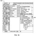
- FIG. 15 is an exemplary screen shot illustrating some more analysis features available in some implementations of the commissioning process.
- FIG. 16 is an exemplary screen shot illustrating some reporting features available in some implementations of the commissioning process.
- FIG. 17 is an exemplary screen shot illustrating some incentive features available in some implementations of the commissioning process.
- FIG. 18 is an exemplary screen shot illustrating applying for incentives available in some implementations of the commissioning process.
- FIG. 19 is an exemplary block diagram illustrating some incentive checker features.
- FIG. 20 is a functional block diagram showing an exemplary embodiment of a controller in a physical space in conjunction with which any of the described embodiments can be implemented.
- FIG. 21 is an exemplary flowchart of a commissioning process in conjunction with which some described embodiments can be implemented.
- FIG. 22 is an exemplary screen shot illustrating some layout features available in some implementations of the commissioning process.
- Described embodiments implement one or more of the described technologies.
- the creation process can include designing the structure and designing and implementing the controllers; teaching the controllers about the devices that will be attached to them; and attaching the building devices to the controllers, such that the building itself understands what is necessary for the commission process.
- the commissioning process then can be done automatically and systematically. As the process is largely automatic, a full history of the commissioning can be created, including a history of each individual device. Once a building has been commissioned, it can be validated such that the quality of commissioning can be shown to outside entities, such as power companies and governmental entities. Such structures can then prove that they can qualify for various incentives.
- FIG. 1 illustrates aspects of a system architecture 100 which is suitable for use with any of the commissioning embodiments described herein.
- the system comprises a physical space 105 .
- a “physical space” should be defined generously. It may refer to a single building, a collection of related buildings, buildings and space around them, an outside space such as a garden with irrigation, a portion of a building, such as a floor, a zone, a room, several rooms, etc.
- the physical space has at least one controller, and maybe many more, deployed within it.
- the controller(s) comprise computer hardware 115 , and memory 120 . If there are multiple controllers, they may be connected using a wired network, a wireless network, or a combination. The multiple controllers may run computer programs using a distributed computing system.
- This distributed computing system may comprise multiple controllers.
- the controllers may be able to choose a master controller by themselves. If the master controller has problems, such as networking problems, the remaining controllers may be able to choose another master controller.
- the master controller may be able to chunk programs and distribute them to the other controllers.
- the memory 120 can be any appropriate volatile or non-volatile storage subsystem.
- the memory may be partially or wholly external, may be volatile memory, e.g., static memory cells, as in FPGAs and some CPLDs; or non-volatile memory, e.g., FLASH memory, as in some CPLDs, or in any other appropriate type of memory cell.
- the memory itself may have within it a model of the physical space 130 .
- This physical space model may be a digital twin, in that the model understands the physical space at a deep level; understanding, for example, the physics of the structure itself, so that it understands how state, such as temperature, diffuses through the structure.
- the physical space model may understand how quickly the heater should heat up, how the heat moves through the building, how the heat from the heater should affect sensors in the physical space, etc.
- Storage 165 may also be included.
- the storage 165 may be removable or non-removable, and includes magnetic disks, magnetic tapes or cassettes, CD-ROMs, CD-RWs, DVDs, flash drives, or any other medium which can be used to store information and which can be accessed within the computing environment 100 .
- the storage 165 stores instructions for the software 185 to implement methods used for automatic commissioning.
- At least one of the controller(s) has an input/output device 155 .
- the input/output device 155 is any sort known to those of skill in the art that allows human/computer interaction to occur, such as some combination of a computer screen, a printer, a touchscreen, a mouse, a screen, a keyboard, a printer, etc.
- the computer controller may also have one or more communication connections 160 . These communication connections may be wired networks, wireless networks, and other types of communication connections as known by those of skill in the art.
- a controller also has a number of devices 135 , 150 associated with it. These devices may be any sort of device that can connect to a controller in a building, as known to those of skill in the art. These may include HVAC equipment, security equipment, entertainment equipment, irrigation equipment, printers, and so on. These devices may pass information from a specific device to the controller and may pass information from the controller to the device. For example, a controller could tell a device to turn on, the device could send the controller error messages, etc. Some devices pass controllers complex information sets about their internal state, etc.
- the controller also has a number of sensors associated with it, such as device sensors 140 , which may pass information from a specific device to the controller and may pass information from the controller to the device. For example, a controller could tell a device sensor to turn on, the sensor device could send the controller messages about the state of the sensor associated with the device, etc. Some device sensors pass controllers complex information sets about their internal state, etc. Space sensors 145 may also be associated with the controller. These, generally, give information about state of the physical space, or some portion of the physical space. They may also accept information from the controller, and pass information to the controller. In some embodiments, the controller can tell whether the space sensor is working as expected by reading the information the space sensor is sending.
- device sensors 140 may pass information from a specific device to the controller and may pass information from the controller to the device. For example, a controller could tell a device sensor to turn on, the sensor device could send the controller messages about the state of the sensor associated with the device, etc. Some device sensors pass controllers complex information sets about their internal state, etc. Space sensors
- the controller can look at the sensors around a specific sensor and see if the values being sent by a sensor are in line with other sensors. In some embodiments, the controller can tell if the space sensor can turn on and off correctly, send information signals correctly etc.
- Example of state that state sensors may read include temperature, humidity, noise levels, air flow noise levels, lighting levels, entertainment noise levels, CO2, VOC, and so on.
- Some of these devices and sensors may be connected by being physically wired to the controller 110 , others may be connected by an interface network connection, e.g., 160 .
- This network connection may be a wired connection, such as an ethernet connection, or may be a wireless connection.
- the controller may be able to determine if the space sensor is wired correctly to the controller.
- Computer-readable storage media 170 any available non-transient tangible media that can be accessed within a computing environment—may also be included.
- Computer readable storage media 170 may comprise instructions 175 and data 180 .
- Data Sources to provide data may be computing devices, such as a general hardware platform servers configured to receive and transmit information over communications connections 160 .
- FIG. 2 illustrates some method embodiments in a general flowchart 200 .
- Technical methods shown in the Figures or otherwise disclosed will be performed automatically, e.g., by computer programs 125 , unless otherwise indicated. Methods may also be performed in part automatically and in part manually to the extent action by a person may be involved, e.g., a person may command that a commissioning process is initiated. No method contemplated as innovative herein is entirely manual. In a given embodiment zero or more illustrated steps of a method may be repeated, perhaps with different devices or models to operate on. Operations in an embodiment may also be done in a different order than the top-to-bottom order that is laid out in FIG. 2 . Operations may be performed serially, in a partially overlapping manner, or fully in parallel.
- flowchart 200 may vary from one performance of the method to another performance of the method.
- the flowchart traversal order may also vary from one method embodiment to another method embodiment.
- Operations may be performed in parallel, serially, or in a partially overlapping manner.
- Operations may also be combined, omitted, renamed, regrouped, or otherwise depart from the illustrated flows, provided that the process performed is operable and conforms to at least one claim.
- a controller is provided. In some embodiments, this may represent multiple controllers. In some embodiments, at operation 210 , multiple devices are provided. In some embodiments, the multiple devices are connected to the controller that is provided in operation 205 or to a different controller in the physical space 105 .
- the controller(s) may control multiple devices. When controlling a device, the controller can, e.g., depending on the device and the controller, turn the devices on, turn the devices off, check that the signals coming from the device in various states is as expected, etc. Examples include the controller signaling a device to enter a certain state (e.g., on, off). The controller may then check to ensure that the device is behaving as expected. For example, the device wires should have certain signals (or lack any signal) when turned off. When the controller turns the device on, other signals may be expected on the wires. Devices may have intermediate states that can be set by the controller, as well.
- a device sensor is provided.
- the controller may also be connected to one or more device sensors that provide information about a device. For example, a controller could tell a hot water heater to turn on high. After a given amount of time, the water in the water heater should have reached some temperature value.
- a device sensor associated with the hot water heater may be able to communicate the water temperature to the controller 110 .
- the controller may know how hot the water should be if the device has been turned on for a specific amount of time at a specific setting.
- the device sensor can help the controller verify or falsify that the device is behaving as expected.
- a space sensor is provided.
- the controller may also control at least one space sensor 145 , within the physical space 105 .
- a space sensor 145 may be used to measure the state of the physical space.
- Common space sensors include temperature sensors, humidity sensors, VOC sensors, noise sensors, water sensors, etc., as discussed above.
- FIG. 4 is a diagram 400 showing a relationship between a controller 405 and an I/O device 410 . Portions of a physical space model may be input into the controller using an I/O device 410 .
- This input device may be any input device as known to those of skill in the art.
- the input device may be a keyboard and/or a mouse which allows a user to input specifications of the physical space, a three dimensional scanner that scans the space and then inputs it directly into the controller, a digital camera that scans the space, determines the coordinates and then inputs those into the controller.
- the input device may be a scanner that scans blueprints, or a wired or wireless connection that sends the model of the physical space in a computer-readable form. This information may be sent to the controller using an optical device, a thumb drive, or another type of device that connects directly or indirectly to the controller.
- a model of device interconnections is provided.
- the controller(s) check if a device is behaving as expected when the device is turned off.
- the controller memory may have information about expected device behavior in various states; this information may be in a model of device interconnections, or in another location. Among other benefits, this checks if the correct wires are wired to the correct controller connectors.
- the controllers turn a device on 235 , using its connection with the controller.
- the controller may then check if the device is behaving as expected. For example, a device should be producing 10V of output along a specific wire when turned on.
- the controller(s) then can check that the appropriate voltage is on a given wire, as well as much other information associated with the device-controller connection.
- a device sensor associated with the device may also be turned on, or if previously turned on, then checked for its state. If a device is behaving as expected, the device state sensor should be at some value, or within some value range. If the device sensor is not within this range, it may indicate a problem with either the device or the device sensor.
- a space sensor is checked to see if it is behaving as expected 240 .
- Space sensors may be checked against the values of other, e.g., nearby space sensors; space sensors may be checked against the behavior of devices that would affect state around the space sensor; if values are not as expected, then there may be problems with the space sensor, the space itself (which may have an undisclosed flaw), a device, which may not be changing state of the space sufficiently, etc.
- devices have specific requirements for validation.
- an HVAC system may have air flow validation requirements, filter leak tests, particle counts, and the like.
- Device sensors or specific state change devices can be placed during construction that allow interaction between the device and the sensor to validate the device.
- some devices for validation require humidity to be reduced within a certain time.
- a humidifier can be built initially into the building that then can be used to raise humidity to a high enough level that the humidity-reducing device (such as an air conditioner) can be validated.
- FIG. 3 is a block diagram 300 that discloses aspects of a physical space model.
- a physical space model 305 (which may be stored in memory 120 ), comprises, for device(s) and sensor(s), expected behavior of the device or sensor 310 , location of the device or sensor 315 , and wiring protocol/expected wiring behavior for the device or sensor 320 .
- Devices may have their own validation requirements 325 ; tests that should be run successfully to officially validate the device. When determining if devices are behaving as expected 230 , 235 , 240 , specific validation tests may be used. When such tests are used, appropriate sensors to test the devices may be incorporated into the initial building design. Correlated behavior 330 between different devices and sensors may also be included. This comprises, for example, sensors that can cross-check each other, sensors whose values should correlate with equipment function, and so on.
- Expected behavior comprises (if applicable) at least some of the signals that the device is expected to send to the controller to indicate functions of the device, current and voltage on the wire connection or connections, signals that the device is expected to send back to the controller when the controller sends signals, current and voltage on the wire(s) associated with the device when the device is turned off, current and voltage on the wire(s) associated with the device when the device is turned on, current and voltage on the wire(s) associated with the device when the device is in various states, the protocol the device is expected to follow for sending messages, etc.
- the controller 505 is wired 515 , 520 to the device and the sensors 510 . Because the physical model understands where each device and sensor is located, what wiring protocols each device and sensor follow and where each should be wired in the controller, the controller can, for a device or a sensor, using software stored within the controller or elsewhere, look at the wiring connection between it and the device and see if it is getting the appropriate signal for each of the wires when the device or sensor is turned off or on.
- the controller understands the signals it should be getting for each wire, in some instances, two devices with the same signal set), if the controller is getting the signals on wire 515 that it expects on 520 , it can determine that the wires have been switched. In some embodiments, the controller also understands the set of signals that the device sends for various states, such as error states, and understands what signals the device understands. These are stored in memory 120 in the controller 110 or within another controller that is part of the same distributed system as this controller 110 , or within a database that the controller 110 can access through a network connection (not shown) or the input/output device 155 , etc.
- the controller can check that it can communicate with the devices (such as sensors) that it is connected to. The controller can then report an error when it finds that a device is not communicating with the controller.
- the controller can send a signal to a device from the device's wiring pin (or pins) and then see what signal it receives back from the device (or device). If it receives the correct signal, then the controller can communicate with the device. In some instances, if the controller receives an incorrect signal or no signal at all, then the controller cannot communicate with the device(s). In such a case, the controller may report this communication error.
- the controller can also perform, for a connector wire, some combination of: a short circuit test, a cut wire test (also known as an open circuit test) or a proper connection test.
- the controller 110 comprises a computer program 125 stored in memory 120 and hardware 115 to be able to run the program 125 and perform such tests when a device or sensor is wired to one or more of its connectors.
- the controller can determine the current and voltage that the wires are expressing, and can also determine the appropriate current and voltage for the wires associated with a device or sensor. If there is an error in any of these, the controller can indicate that an error has occurred. This indication may comprise writing to a file, displaying that an error has occurred on a display device, printing a report, making a noise, or any other error indication as known by those of skill in the art.
- the controller can turn each device and sensor on. Once turned on, the controller can determine that the wiring connection is behaving as expected 515 , 520 when turned on, which may entail giving the correct signal/voltage and current. If there is an error in any of these, the controller can indicate that an error has occurred. This indication may comprise writing to a file, displaying that an error has occurred on a display device, printing a report, making a noise, or any other error indication as known by those of skill in the art. In some embodiment, the errors the controller finds are reported on a display device.
- an illustrative embodiment of an automatic commissioning progress report screen 600 is disclosed. This screen may be shown on a display device associated with the controller.
- the groupings of objects in the physical space that meet certain criteria are shown.
- Some possible groupings are subsystems 605 , zones 610 , equipment 615 , and sensors 620 .
- Subsystems may be large groupings, such as floors in a building. Zones may have smaller groupings within the subsystem such as portions of a floor of a building, e.g., living room, kitchen, laundry, etc.
- Equipment may be devices controllable by the subsystem that are not sensors. Other groupings are possible as well.
- the display changes as portions of the system record their commission results.
- a sensor, equipment, zone, or subsystem When a sensor, equipment, zone, or subsystem is tested, its results are displayed as either pass 625 , check 630 , or fail 635 .
- Pass 625 is indicated where expected behavior was produced. For example, the results could reach a threshold value, such as a numerical value, a percent of a maximum or minimum value, and so on. Pass results, such at the threshold value, may be set by a user, a commissioning standard, a default equipment pass threshold value, etc.
- Fail 635 is indicated when expected behavior is not produced.
- Check 630 is indicated when the behavior of the device is unclear and manual interpretation is required.
- the controller may enable the boiler and then check that the temperature on the boiler output (which may be a sensor) increases properly. Corresponding zones to the boiler are expected to see an increase in temperature. If insufficient temperature increase in the sensors of these corresponding zones is recorded, then the results may comprise “check” or “fail”. If the controller does not detect enough of an increase in the corresponding zones the results are ambiguous and will require human intervention.
- devices that are near each other, connect to each other, or both may perform cross check validation. For example temperature sensors in adjoining areas should have temperature values that are within a range of each other. If one sensor value is off by a certain amount, that sensor may fail commissioning. If there are correct relationship behaviors between the sensors then the sensor may pass. If there is a correct relationship between a device and nearby sensors, then the sensor may pass. Many devices have correlated behavior, and as such may be cross-checked against each other.
- the building may be turned on to run in its normal fashion by selecting a “deploy” button 640 .
- FIG. 7 is an exemplary diagram 700 that describes device-controller interaction.
- the commissioning process can determine when the wiring has been swapped, that is, device wire A was expected to be wired to controller wire A but instead has been wired to controller wire pin B, and vice versa. This also works for devices with more wires.
- the controller can determine when a device A at wire A has instead been wired to controller location C.
- the commissioning process will detect this and determine the correct location for the device.
- FIG. 8 is an exemplary diagram 800 of a simplified model of a physical space.
- the controller can use sensors to cross-check themselves.
- This simplified physical space model 800 comprises the location of multiple sensors 835 , 845 , 850 and a heater 840 within a building portion that has multiple zones 815 , 820 , 825 , 830 .
- Walls 810 , windows 855 , and other features are included in the model of the physical space that affect the way state, such as temperature, moves through the physical space.
- the physical space neural network may know where physical features like walls 810 and windows 855 are, and as such understands how far apart the various devices are from each other.
- the physical space neural network may understand the physical coordinates of devices, such as heaters, 840 , such that the neural network understand how heat (or other state) is transported throughout the physical space, including through such features as walls and ceilings.
- a sensor 835 that is some number of feet away from the heater should register a value within a certain range, or there is a problem with the heater, the sensor, or the physical space configuration.
- Another sensor 845 some number of feet away with a wall between the heater 840 and the sensor 835 , should register a temperature within a certain number of degrees from sensors 835 and 850 .
- sensor 835 reports the expected change in temperature when the heater is turned on, but sensor 850 does not, then one assumption that might be made is that sensor 850 is not working correctly, but sensor 835 and the heater are. If another sensor 845 records temperature in a different location that reflects the expected value when taking into account the distance from the heater, and the walls, etc. between them, then sensor 850 shows a good chance of having a flaw. In this way, sensors 835 , 845 , and 850 can perform cross-checks on each other. Other equipment within a physical structure can perform similar cross-checks.
- Sensors can also be used to check that devices are properly commissioned.
- a device such as a heater 840 may be near a sensor 860 that reports on the state of the device.
- the plans for these sensors that help with commissioning may be put in at the design state, and then built such that the physical space can commission itself, as the sensor 860 will report if a device, e.g., heater 840 is operating correctly.
- These sensors may also help ensure that devices are running properly throughout the lifetime of the physical space.
- the controller may turn on the device for a certain time at a certain speed (if applicable) and then check the associated sensor. If the sensor changes state appropriately, then the device may have passed at least one test towards full commissioning.
- the device may affect multiple sensors, each of which may be checked by the controller. If the physical space uses multiple controllers, they may be connected using a distributed system, and so may be able to communicate such that sensors and devices wired to different controllers can automatically be used in the commissioning process.
- Controllers also have access to databases of the physical space such that they can check that sensors in the space record the correct information for device activity, and sensors can cross-check each other for consistency.
- an exemplary embodiment commissioning screen 900 is shown.
- those sections may be displayed on a panel 930 on the progress report. These may be displayed such that the section of the physical space 915 (e.g., sensors, equipment, zones, subsystems) that is being commissioned is displayed have the portions that have passed, failed, or fall into the check category show up differentiated in some fashion, such as in different colors.
- An exemplary screenshot of such a display is shown. In it, a subsystem that is being commissioned is displayed.
- a list of the components (e.g., resources, sensors, devices) that are being commissioned is displayed, e.g., sequentially, with an icon 910 indicating that the component is being currently commissioned (e.g., as shown with reference to FIG. 2 ), along with the name of the component, e.g. temperature sensor 920 .
- an icon 910 indicating that the component is being currently commissioned (e.g., as shown with reference to FIG. 2 ), along with the name of the component, e.g. temperature sensor 920 .
- FIG. 2 the name of the component
- FIG. 2 temperature sensor
- That portion of the building may be displayed 935 on the screen along with icons of the objects (device, sensor) being commissioned.
- Object names may be displayed in a panel 925 ; a mark is shown in the panel when the sensor is being automatically commissioned (in this case, a dashed-line circle indicting that a humidity sensor is being commissioned) 910 . Another mark is shown (in this case, a check) when the sensor has been successfully commissioned 920 .
- the representation of the object being commissioned may be highlighted on the screen, e.g., 940 , the humidity sensor icon that is currently being commissioned.
- the area of the building being automatically commissioned is shown in the right panel 935 .
- the physical space model may be decided hierarchically, with each hierarchy step from lowest to highest, commissioned in turn.
- the hierarchical elements are shown in the far-left panel 915 from bottom to top, with the bottom sensors 940 , being the lowest of the hierarchy and the first to be commissioned.
- Equipment 945 is at the same level or next level of hierarchy, then 950 zones are a step up in hierarchy, with subsystems 955 being the top of the hierarchy. Sensors are first checked, then the equipment, then zones, then subsystems. Other orders of commissioning are also within the scope of this disclosure.
- an exemplary screenshot 1000 of equipment control loops being commissioned is shown.
- the equipment control loops are shown in the right panel 1010 .
- the names of individual pieces of equipment 1005 in the control loops are shown in a panel 1015 .
- This panel 1015 also shows whether or not a piece of equipment has been commissioned; here the same checks are used as seen in FIG. 9 , though other methods are also envisioned. Whether a piece of equipment is on or off is also noted 1030 .
- the far left panel 1020 shows progress of the automatic commissioning. In this snapshot 1025 47% of the equipment has been commissioned; 9 have passed, 0 checked, and 0 failed.
- an exemplary embodiment screenshot 1100 shows zones of the building being commissioned.
- the floor the zones are on are displayed in the right panel 1110 .
- the zone itself being commissioned is shown in a middle panel 115 .
- a mark is displayed 1120 in the middle panel 1115 indicating that commissioning is currently occurring.
- a spinning circle indicates current commissioning, but other marks are envisioned.
- the zones are commissioned, they are displayed (with a check, by changing color, intensity of color, or by another method) in the middle panel 1115 .
- an error has been found, which is indicated by a distinctive mark 1105 , in this illustrative example, an explanation point.
- an exemplary embodiment commissioning screenshot 1200 is shown.
- the commissioning screen provides information about that specific error.
- the overall location of the error many be indicated with a distinctive mark indicating what larger hierarchical grouping the error has occurred in.
- four major groupings 1245 Outdoor, Floor 1, Floor 2, Floor 3.
- “Floor 3” 1235 has an indication (!) that there is a commissioning error on this floor.
- “Outdoor” 1240 has an indiction ( ⁇ , in the instant case) showing that this grouping has passed commissioning.
- Selecting a device 1205 with an indicated error 1210 brings up a screen 1215 that tells more information 1220 about the device 1205 , such as name, the kind of device, the interface, the manufacturer, the mode, etc. Drop-down menus are also included in the illustrative example 1215 . In the described embodiment, the options are “Manual Mode” 1225 , “Analysis” 1230 , “Analysis Details,” and “Commissioning History”.
- FIG. 13 discloses an exemplary commissioning screenshot 1300 with a commissioning report drawer open to display manual mode 1305 .
- the user can manually choose 1310 to pass the device in question (here a humidity sensor 1320 ), fail the device, or defer until a later time. If the device is manually passed, (by, e.g., selecting the pass button) the automatic commissioning system will pass the device in that it will consider the device correctly commissioned with no further action. If the device is failed, the automatic commissioner will consider the device to have failed the automatic commissioning until the user passes it using this screen, or the device is automatically commissioned again and passes, or until another action happens. If the device is deferred, the device will remain in its current state.
- a user can add notes 1315 , which, in some embodiments, will become part of the permanent record. This allows users at a later date to have a full record at their fingertips of the building behavior down to specifics of commissioning of each device since installation.
- FIG. 14 discloses a commissioning screenshot 1400 with a commissioning report drawer open to display analysis.
- a device has a commissioning challenge, there are many resources to help determine what the matter might be. Opening the drawer “Analysis” 1405 opens the analysis window 1410 . It shows, for the chosen device (in this case, a CO 2 sensor 1415 ), the certainty that the commissioning is accurate 1420 (which is a record of how close the device results were to presumed perfect results), and a pictorial representation indicating more details, such as, if there were errors recorded, what percentage of the time the error(s) occurred, where the errors occurred, etc.
- the chosen device in this case, a CO 2 sensor 1415
- the certainty that the commissioning is accurate 1420 which is a record of how close the device results were to presumed perfect results
- a pictorial representation indicating more details, such as, if there were errors recorded, what percentage of the time the error(s) occurred, where the errors occurred, etc.
- Devices may have components. In some implementations, the components of the device, and the percentage of those components that passed are shown. These may be shown by opening a further drawer, or using some other method. Similar details may be shown about the components that are shown about the device.
- FIG. 15 discloses a screenshot 1500 with analysis details of the CO 2 device at 1505 . Why a specific device failed may involve determining which specific portion of the device failed. This may be able to be determined by looking at provided analysis details.
- the illustrative screenshot 1500 shown in FIG. 15 discloses analysis details 1510 from the analysis drawer 1425 . The components that are tested to commission device, and the percentage of those components that passed are shown. “Passing” may be a statistical function, an artificial intelligence calculation, may use historical data, or may use some combination of all of these to determine passing and failing.
- the data may be represented graphically, may be in text, may be in pictures, or may be some combination of the above.
- FIG. 16 discloses a screenshot 1600 of a commissioning history 1605 of a device, e.g., a CO 2 sensor.
- a history of every commissioning event that happens since installation may be kept.
- the system may maintain an event log, may save snapshots, may save certain types of data, may sample data at certain times or for certain actions, etc. Reports may be available to help to understand the history of a device.
- the information shown is a history of commissioning runs, a name of the person who, e.g. requested the commissioning run, and notes that can be written by a user. Other implementations may have other information stored.
- FIG. 17 discloses an exemplary screenshot 1700 for an an incentive checker.
- the system may determine what type of incentives from government entities, utilities, etc., for which a building may be eligible.
- the types of validation that a building has passed are shown. In this exemplary embodiment, it is shown that the building has been validated, the system has been validated, the wiring has been validated, the system commissioned, and the system deployed.
- the pane shown at 1710 displays incentives that this space is qualified for, and the organization that may give the incentives 1715 .
- FIG. 18 discloses one method that may be used in some embodiments to apply for the incentives that are discovered.
- An “apply” button 1805 can be selected to apply for those incentives 1710 .
- an incentive database may be used to keep track of incentives that are available for the physical space. These incentives may be uploaded automatically into the database from participating organizations, may be hand-input, may be placed in using a combination of automatic and hand input, or may be placed in using another method.
- the commissioning results 1910 are compared with the requirements for the incentives in the incentive database 1905 . Those incentives that are found that meet the requirements are then displayed on an I/O device (e.g., 155 ) using an incentive display 1915 Screenshot 1700 discloses an illustrative example of such a display 1705 .
- the entity offering the incentives, and contact info is shown (e.g., Pacific Gas and Power Company), as well as the specific incentives that the physical space is qualified for, the name of the incentive, and the amount that the incentive is worth 1710 .
- an incentive deployer is disclosed. This, in combination with the incentive database 1905 has the ability to apply for the incentives that the physical space is eligible for. It may do this by filling out forms using information gleaned from the automatic commissioning, and information about the specifics of applying for the incentives. It may create paperwork, and/or send the paperwork to the appropriate location.
- An example of applying for incentives is shown in screenshot 1800 . In this illustrative example, a user checks “I consent to sharing performance data with my utility,” and then is able to select an “apply” button 1805 .
- FIG. 20 depicts one topology 2000 for commissioning a space automatically.
- one or more controllers comprise one or more memories 2010 and one or more processors 2015 .
- the controller(s) 2005 comprises a physical space model 2020 , in some instances stored in memory 2010 , which comprises a digital model of the physical space that is to be commissioned. Within this physical space model, there may be a model of a device 2025 . This device model may be stored in memory 2010 . In some embodiments, the device model is stored outside the physical space model.
- the device model 2025 may comprise a device wiring protocol 2030 , device behavioral data 2035 , device error data 2040 , and past commissioning data 2045 .
- Device wiring protocol 2030 indicates the protocol the device uses; specific device behavioral data 2035 indicates specific data associated with the device that may be useful during commissioning, and device error data indicates error messages that the device may send through its wiring. These categories may or may not overlap.
- a building is often commissioned prior to its first opening, and then commissioned every three to five years after that.
- Some innovative embodiments such as those illustrated in FIGS. 9 - 18 , keep track of previous commissioning information 2045 , such as previous commissioning done using the illustrated examples shown herein, including human-written notes from previous commissioning incidents stored within the system, such as those shown in FIG. 13 at 1315 .
- the previous commissioning information is available when needed, such as when a building is commissioned again.
- Specific validation tests 2050 for certain devices may be included. These validation tests may involve certain other device operations 2055 , such as a specific device being turned on and checked, and certain sensors being checked, and what their values should be 2060 .
- a smoke machine (a device) may be used for a certain amount of time, then after a second period of time a sensor at a certain location with the capability to check indoor air quality checks if the appropriate value is being recorded at the sensor.
- commissioning may require that a certain amount of humidity should be removed from the air within a given period of time. This may require both a vent be opened (a first device) and an air conditioner or other dehumidifier be turned on (a second device).
- Sensors may be built into a building to allow automatic commissioning to occur.
- a sensor that monitors humidity may also need to be checked for within some range of a given value after a period of time.
- Other validation tests may require multiple sensors being checked, or it may require checking multiple functions of a multiple function sensor, such as, for example, indoor air quality and CO 2 concentration.
- commissioning engine 2065 runs the commissioning software using the processor 2015 . In some embodiments, the running of the commissioning engine is divided over multiple processors running a distributed system.
- the device is expected to be wired to the controller at a specific position. If the device has multiple wires, each wire has its own location, its own protocol, etc. In some embodiments, this device wiring position information is stored with relationship to the controller itself.
- FIG. 22 gives an example of an embodiment with which specific devices can be designated to be wired to specific controller locations.
- FIG. 21 illustrates a method 2100 for automatically commissioning a physical space.
- the operations of method 2100 presented below are intended to be illustrative. In some embodiments, method 2100 may be accomplished with one or more additional operations not described, and/or without one or more of the operations discussed. Additionally, the order in which the operations of method 2100 are illustrated in FIG. 21 and described below is not intended to be limiting.
- method 2100 may be implemented in one or more processing devices (e.g., multiple processors running in a distributed system with multiple controllers, a digital processor, an analog processor, a digital circuit designed to process information, an analog circuit designed to process information, a state machine, and/or other mechanisms for electronically processing information).
- the one or more processing devices may include one or more devices executing some or all of the operations of method 2100 in response to instructions stored electronically on an electronic storage medium.
- the one or more processing devices may include one or more devices configured through hardware, firmware, and/or software to be specifically designed for execution of one or more of the operations of method 2100 .
- a device in the physical space that is to be commissioned is selected, e.g., by the commissioning engine.
- the physical space model (or a different location in memory) may have, in memory 2010 , a model of the devices to be commissioned.
- FIG. 22 and the surrounding text gives an example of a screenshot associated with a controller that may be used to determine where a device should be wired on a controller.
- the device wires are checked to see if they follow the correct protocol.
- the correct protocol can be found, e.g., in a device wiring protocol 2030 database location stored with the device model 2025 . There may also be a separate device wiring position 2070 , or those may be included in the device wiring protocol.
- the information about the device may be already understood by the controller, and stored in a database, the information about the device protocol may be input by a user, such that the controller has access to it, or a combination of the two may be used.
- the sensors are checked to see if they are exhibiting expected behaviors, depending on device state.
- a sensor may need to be checked. For example, to check if an air conditioner is working appropriately, a nearby sensor that checks temperature needs to be identified, or may already be identified. The temperature on the sensor then needs to be checked; the air conditioner needs to be turned on for a certain time by the controller using the air conditioner protocol stored in memory in the controller (or a controller within a distributed controller system); then the sensor needs to be checked again to see if the temperature has changed by the desired amount. If it has, the device passes the commissioning, if the temperature has not decreased by the required amount, then the device has either failed, or needs checking.
- device behavior is documented and stored such that it can be retrieved.
- This documentation is such that it can be retrieved when desired. This may be stored by methods known to those of skill in the art.
- FIG. 22 illustrates aspects of a system architecture which is suitable for use with any of the commissioning embodiments described herein.
- the illustrative screenshot embodiment 2200 allows a user to view or specify the expected device layout of a controller.
- a controller is wired to a device through a controller connector, a module connector that itself connects to a controller, etc.
- a controller connector is shown at 2220 .
- This controller connector is attached to a module connector 2205 .
- Modules 2215 are indicated on the screen using grouped, numbered 2235 module connectors 2205 .
- This module 2215 has six module connectors that will connect to devices.
- This controller represented in screen 2200 has eight potential module locations, one of which are currently empty. Other numbers of modules in a controller, and device connectors in a module are also within the scope of this disclosure.
- the specific devices that are to be wired to the controller are shown as device icons attached to their respective module connecters.
- the device is a Three Way Valve, with a 24 VAC (3-wire) protocol. It is attached to module 1 2225 . It has three wires, which are of type ( ⁇ ), (O), and (C) from left to right, and which are in three distinct locations on the controller.
- a device wire is wired to the lower left connection 2230 of the controller, the controller knows that it is to be a wire on a Three-Way Valve, with protocol 24 VAC (3-WIRE) and the specific wire is to be of type ( ⁇ ).
- the controller can see what information is on the wire when connected, what signals the wire accepts, and what signals the wire is expected to return, etc.
- the controller understands what to do to test if the correct wire has been connected to that direct controller location. If wires have been swapped on a device (for example, the ( ⁇ ) and (O) wires are swapped such that the (O) wire is in the far lower left position 2230 , the controller may be able to determine this, as it has the information about what signals can be expected to be sent and received on the wires.
- the controller may send a message to the module (through the module connecter and the circuit board) to tell an indicator 2235 on the module to signal that the correct wire is in place.
- the indicator may indicate that the wire is correct with a light, such as a green LED light, a noise, etc.
- the indicator may indicate that the wire is incorrect with a light, such as a red LED light, a noise, etc.
- the light when a wire is connected in the module (the module in the controller, the controller having been told what wire to expect) the light will light up green if the correct wire is found to be connected (by the controller, module, or a combination) or will light up red if the correct wire is not found to be connected (by the controller, module, or some other combination).
- Embodiments are not limited to the specific implementations, arrangements, displays, features, approaches, or scenarios provided herein.
- a given embodiment may include additional or different technical features, mechanisms, and/or data structures, for instance, and may otherwise depart from the examples provided herein.
Abstract
Description
Claims (20)
Priority Applications (2)
| Application Number | Priority Date | Filing Date | Title |
|---|---|---|---|
| US17/190,541 US11596079B2 (en) | 2020-08-26 | 2021-03-03 | Methods, controllers, and machine-readable storage media for automated commissioning of equipment |
| US18/102,396 US20230180420A1 (en) | 2020-08-26 | 2023-01-27 | Methods, controllers, and machine-readable storage media for automated commissioning of equipment |
Applications Claiming Priority (2)
| Application Number | Priority Date | Filing Date | Title |
|---|---|---|---|
| US202063070460P | 2020-08-26 | 2020-08-26 | |
| US17/190,541 US11596079B2 (en) | 2020-08-26 | 2021-03-03 | Methods, controllers, and machine-readable storage media for automated commissioning of equipment |
Related Child Applications (1)
| Application Number | Title | Priority Date | Filing Date |
|---|---|---|---|
| US18/102,396 Continuation US20230180420A1 (en) | 2020-08-26 | 2023-01-27 | Methods, controllers, and machine-readable storage media for automated commissioning of equipment |
Publications (2)
| Publication Number | Publication Date |
|---|---|
| US20220066434A1 US20220066434A1 (en) | 2022-03-03 |
| US11596079B2 true US11596079B2 (en) | 2023-02-28 |
Family
ID=79293839
Family Applications (21)
| Application Number | Title | Priority Date | Filing Date |
|---|---|---|---|
| US17/021,965 Active US11553618B2 (en) | 2020-08-26 | 2020-09-15 | Methods and systems of building automation state load and user preference via network systems activity |
| US17/135,212 Active 2041-01-05 US11490537B2 (en) | 2020-08-26 | 2020-12-28 | Distributed building automation controllers |
| US17/135,591 Active US11477905B2 (en) | 2020-08-26 | 2020-12-28 | Digital labeling control system terminals that enable guided wiring |
| US17/143,556 Active US11229138B1 (en) | 2020-08-26 | 2021-01-07 | Controller modules |
| US17/151,337 Active 2042-06-16 US11871505B2 (en) | 2020-08-26 | 2021-01-18 | Automated line testing |
| US17/151,365 Active 2041-05-18 US11706891B2 (en) | 2020-08-26 | 2021-01-18 | Perceptible indicators of wires being attached correctly to controller |
| US17/175,944 Abandoned US20220067226A1 (en) | 2020-08-26 | 2021-02-15 | Automated Point Mapping Interface |
| US17/177,061 Pending US20220066432A1 (en) | 2020-08-26 | 2021-02-16 | Control System Having an Adjacent Electronic Display for Auto Labeling and Guided Wiring |
| US17/190,541 Active 2041-05-26 US11596079B2 (en) | 2020-08-26 | 2021-03-03 | Methods, controllers, and machine-readable storage media for automated commissioning of equipment |
| US17/204,668 Pending US20220066722A1 (en) | 2020-08-26 | 2021-03-17 | Controller With Moveable Interactive Screen |
| US17/216,565 Pending US20220067227A1 (en) | 2020-08-26 | 2021-03-29 | Automated Point Mapping Generation |
| US17/224,976 Pending US20220067230A1 (en) | 2020-08-26 | 2021-04-07 | Building Automation Programming Using UI Representations of Physical Models |
| US17/347,672 Pending US20220066528A1 (en) | 2020-08-26 | 2021-06-15 | Energy Efficient Sensor |
| US17/409,636 Pending US20220066754A1 (en) | 2020-08-26 | 2021-08-23 | Semantic Labeling Analysis |
| US17/410,072 Active 2041-08-26 US11737231B2 (en) | 2020-08-26 | 2021-08-24 | Method and apparatus for generalized control of devices |
| US17/842,308 Pending US20220312618A1 (en) | 2020-08-26 | 2022-06-16 | Method of Digital Labeling Control System Terminals That Enables Guided Wiring |
| US17/865,228 Active US11832413B2 (en) | 2020-08-26 | 2022-07-14 | Method of building automation heat load and user preference inferring occupancy via network systems activity |
| US17/820,976 Active US11856723B2 (en) | 2020-08-26 | 2022-08-19 | Distributed building automation controllers |
| US17/990,350 Pending US20230120713A1 (en) | 2020-08-26 | 2022-11-18 | Perceptible Indicators That Wires are Attached Correctly to Controller |
| US18/102,396 Pending US20230180420A1 (en) | 2020-08-26 | 2023-01-27 | Methods, controllers, and machine-readable storage media for automated commissioning of equipment |
| US18/209,383 Pending US20230328912A1 (en) | 2020-08-26 | 2023-06-13 | Method and Apparatus for Generalized Control of Devices |
Family Applications Before (8)
| Application Number | Title | Priority Date | Filing Date |
|---|---|---|---|
| US17/021,965 Active US11553618B2 (en) | 2020-08-26 | 2020-09-15 | Methods and systems of building automation state load and user preference via network systems activity |
| US17/135,212 Active 2041-01-05 US11490537B2 (en) | 2020-08-26 | 2020-12-28 | Distributed building automation controllers |
| US17/135,591 Active US11477905B2 (en) | 2020-08-26 | 2020-12-28 | Digital labeling control system terminals that enable guided wiring |
| US17/143,556 Active US11229138B1 (en) | 2020-08-26 | 2021-01-07 | Controller modules |
| US17/151,337 Active 2042-06-16 US11871505B2 (en) | 2020-08-26 | 2021-01-18 | Automated line testing |
| US17/151,365 Active 2041-05-18 US11706891B2 (en) | 2020-08-26 | 2021-01-18 | Perceptible indicators of wires being attached correctly to controller |
| US17/175,944 Abandoned US20220067226A1 (en) | 2020-08-26 | 2021-02-15 | Automated Point Mapping Interface |
| US17/177,061 Pending US20220066432A1 (en) | 2020-08-26 | 2021-02-16 | Control System Having an Adjacent Electronic Display for Auto Labeling and Guided Wiring |
Family Applications After (12)
| Application Number | Title | Priority Date | Filing Date |
|---|---|---|---|
| US17/204,668 Pending US20220066722A1 (en) | 2020-08-26 | 2021-03-17 | Controller With Moveable Interactive Screen |
| US17/216,565 Pending US20220067227A1 (en) | 2020-08-26 | 2021-03-29 | Automated Point Mapping Generation |
| US17/224,976 Pending US20220067230A1 (en) | 2020-08-26 | 2021-04-07 | Building Automation Programming Using UI Representations of Physical Models |
| US17/347,672 Pending US20220066528A1 (en) | 2020-08-26 | 2021-06-15 | Energy Efficient Sensor |
| US17/409,636 Pending US20220066754A1 (en) | 2020-08-26 | 2021-08-23 | Semantic Labeling Analysis |
| US17/410,072 Active 2041-08-26 US11737231B2 (en) | 2020-08-26 | 2021-08-24 | Method and apparatus for generalized control of devices |
| US17/842,308 Pending US20220312618A1 (en) | 2020-08-26 | 2022-06-16 | Method of Digital Labeling Control System Terminals That Enables Guided Wiring |
| US17/865,228 Active US11832413B2 (en) | 2020-08-26 | 2022-07-14 | Method of building automation heat load and user preference inferring occupancy via network systems activity |
| US17/820,976 Active US11856723B2 (en) | 2020-08-26 | 2022-08-19 | Distributed building automation controllers |
| US17/990,350 Pending US20230120713A1 (en) | 2020-08-26 | 2022-11-18 | Perceptible Indicators That Wires are Attached Correctly to Controller |
| US18/102,396 Pending US20230180420A1 (en) | 2020-08-26 | 2023-01-27 | Methods, controllers, and machine-readable storage media for automated commissioning of equipment |
| US18/209,383 Pending US20230328912A1 (en) | 2020-08-26 | 2023-06-13 | Method and Apparatus for Generalized Control of Devices |
Country Status (1)
| Country | Link |
|---|---|
| US (21) | US11553618B2 (en) |
Cited By (1)
| Publication number | Priority date | Publication date | Assignee | Title |
|---|---|---|---|---|
| US20230120713A1 (en) * | 2020-08-26 | 2023-04-20 | PassiveLogic, Inc. | Perceptible Indicators That Wires are Attached Correctly to Controller |
Families Citing this family (75)
| Publication number | Priority date | Publication date | Assignee | Title |
|---|---|---|---|---|
| US9411327B2 (en) | 2012-08-27 | 2016-08-09 | Johnson Controls Technology Company | Systems and methods for classifying data in building automation systems |
| US10534326B2 (en) | 2015-10-21 | 2020-01-14 | Johnson Controls Technology Company | Building automation system with integrated building information model |
| US11947785B2 (en) | 2016-01-22 | 2024-04-02 | Johnson Controls Technology Company | Building system with a building graph |
| US11268732B2 (en) | 2016-01-22 | 2022-03-08 | Johnson Controls Technology Company | Building energy management system with energy analytics |
| WO2017173167A1 (en) | 2016-03-31 | 2017-10-05 | Johnson Controls Technology Company | Hvac device registration in a distributed building management system |
| US11774920B2 (en) | 2016-05-04 | 2023-10-03 | Johnson Controls Technology Company | Building system with user presentation composition based on building context |
| US10417451B2 (en) | 2017-09-27 | 2019-09-17 | Johnson Controls Technology Company | Building system with smart entity personal identifying information (PII) masking |
| US10505756B2 (en) | 2017-02-10 | 2019-12-10 | Johnson Controls Technology Company | Building management system with space graphs |
| US10684033B2 (en) | 2017-01-06 | 2020-06-16 | Johnson Controls Technology Company | HVAC system with automated device pairing |
| US11900287B2 (en) | 2017-05-25 | 2024-02-13 | Johnson Controls Tyco IP Holdings LLP | Model predictive maintenance system with budgetary constraints |
| US20190361412A1 (en) | 2017-02-10 | 2019-11-28 | Johnson Controls Technology Company | Building smart entity system with agent based data ingestion and entity creation using time series data |
| US11360447B2 (en) | 2017-02-10 | 2022-06-14 | Johnson Controls Technology Company | Building smart entity system with agent based communication and control |
| US11764991B2 (en) | 2017-02-10 | 2023-09-19 | Johnson Controls Technology Company | Building management system with identity management |
| US10095756B2 (en) | 2017-02-10 | 2018-10-09 | Johnson Controls Technology Company | Building management system with declarative views of timeseries data |
| US10515098B2 (en) | 2017-02-10 | 2019-12-24 | Johnson Controls Technology Company | Building management smart entity creation and maintenance using time series data |
| US10740503B1 (en) * | 2019-01-17 | 2020-08-11 | Middle Chart, LLC | Spatial self-verifying array of nodes |
| US11900021B2 (en) | 2017-02-22 | 2024-02-13 | Middle Chart, LLC | Provision of digital content via a wearable eye covering |
| US11468209B2 (en) | 2017-02-22 | 2022-10-11 | Middle Chart, LLC | Method and apparatus for display of digital content associated with a location in a wireless communications area |
| US11900023B2 (en) | 2017-02-22 | 2024-02-13 | Middle Chart, LLC | Agent supportable device for pointing towards an item of interest |
| US11042144B2 (en) | 2017-03-24 | 2021-06-22 | Johnson Controls Technology Company | Building management system with dynamic channel communication |
| US11327737B2 (en) | 2017-04-21 | 2022-05-10 | Johnson Controls Tyco IP Holdings LLP | Building management system with cloud management of gateway configurations |
| US10788229B2 (en) | 2017-05-10 | 2020-09-29 | Johnson Controls Technology Company | Building management system with a distributed blockchain database |
| US11022947B2 (en) | 2017-06-07 | 2021-06-01 | Johnson Controls Technology Company | Building energy optimization system with economic load demand response (ELDR) optimization and ELDR user interfaces |
| WO2018232147A1 (en) | 2017-06-15 | 2018-12-20 | Johnson Controls Technology Company | Building management system with artificial intelligence for unified agent based control of building subsystems |
| EP3655826A1 (en) | 2017-07-17 | 2020-05-27 | Johnson Controls Technology Company | Systems and methods for agent based building simulation for optimal control |
| US11422516B2 (en) | 2017-07-21 | 2022-08-23 | Johnson Controls Tyco IP Holdings LLP | Building management system with dynamic rules with sub-rule reuse and equation driven smart diagnostics |
| US20190034066A1 (en) | 2017-07-27 | 2019-01-31 | Johnson Controls Technology Company | Building management system with central plantroom dashboards |
| US20190096214A1 (en) | 2017-09-27 | 2019-03-28 | Johnson Controls Technology Company | Building risk analysis system with geofencing for threats and assets |
| US11314726B2 (en) | 2017-09-27 | 2022-04-26 | Johnson Controls Tyco IP Holdings LLP | Web services for smart entity management for sensor systems |
| US10962945B2 (en) | 2017-09-27 | 2021-03-30 | Johnson Controls Technology Company | Building management system with integration of data into smart entities |
| US11281169B2 (en) | 2017-11-15 | 2022-03-22 | Johnson Controls Tyco IP Holdings LLP | Building management system with point virtualization for online meters |
| US10809682B2 (en) | 2017-11-15 | 2020-10-20 | Johnson Controls Technology Company | Building management system with optimized processing of building system data |
| US11127235B2 (en) | 2017-11-22 | 2021-09-21 | Johnson Controls Tyco IP Holdings LLP | Building campus with integrated smart environment |
| US11954713B2 (en) | 2018-03-13 | 2024-04-09 | Johnson Controls Tyco IP Holdings LLP | Variable refrigerant flow system with electricity consumption apportionment |
| US11016648B2 (en) | 2018-10-30 | 2021-05-25 | Johnson Controls Technology Company | Systems and methods for entity visualization and management with an entity node editor |
| US11927925B2 (en) | 2018-11-19 | 2024-03-12 | Johnson Controls Tyco IP Holdings LLP | Building system with a time correlated reliability data stream |
| US11775938B2 (en) | 2019-01-18 | 2023-10-03 | Johnson Controls Tyco IP Holdings LLP | Lobby management system |
| US10788798B2 (en) | 2019-01-28 | 2020-09-29 | Johnson Controls Technology Company | Building management system with hybrid edge-cloud processing |
| KR102183309B1 (en) * | 2019-05-21 | 2020-11-26 | 성균관대학교산학협력단 | A multi-type pressure sensor |
| US11894944B2 (en) | 2019-12-31 | 2024-02-06 | Johnson Controls Tyco IP Holdings LLP | Building data platform with an enrichment loop |
| US20210200807A1 (en) | 2019-12-31 | 2021-07-01 | Johnson Controls Technology Company | Building data platform with a graph change feed |
| US11640486B2 (en) | 2021-03-01 | 2023-05-02 | Middle Chart, LLC | Architectural drawing based exchange of geospatial related digital content |
| US11537386B2 (en) | 2020-04-06 | 2022-12-27 | Johnson Controls Tyco IP Holdings LLP | Building system with dynamic configuration of network resources for 5G networks |
| US11874809B2 (en) | 2020-06-08 | 2024-01-16 | Johnson Controls Tyco IP Holdings LLP | Building system with naming schema encoding entity type and entity relationships |
| USD944271S1 (en) * | 2020-06-21 | 2022-02-22 | Apple Inc. | Display screen or portion thereof with graphical user interface |
| US11283669B1 (en) * | 2020-09-04 | 2022-03-22 | Johnson Controls Tyco IP Holdings LLP | Building management system with control framework |
| US11954154B2 (en) | 2020-09-30 | 2024-04-09 | Johnson Controls Tyco IP Holdings LLP | Building management system with semantic model integration |
| US11397773B2 (en) | 2020-09-30 | 2022-07-26 | Johnson Controls Tyco IP Holdings LLP | Building management system with semantic model integration |
| US20220138492A1 (en) | 2020-10-30 | 2022-05-05 | Johnson Controls Technology Company | Data preprocessing and refinement tool |
| AU2022237623A1 (en) | 2021-03-17 | 2023-10-19 | Johnson Controls Tyco IP Holdings LLP | Systems and methods for determining equipment energy waste |
| FR3121289B1 (en) * | 2021-03-26 | 2023-06-30 | Schneider Electric Ind Sas | Electrical connection cabinet |
| USD1002556S1 (en) * | 2021-06-01 | 2023-10-24 | Siemens Aktiengesellschaft | Display module of an overcurrent release |
| US11769066B2 (en) | 2021-11-17 | 2023-09-26 | Johnson Controls Tyco IP Holdings LLP | Building data platform with digital twin triggers and actions |
| US11899723B2 (en) | 2021-06-22 | 2024-02-13 | Johnson Controls Tyco IP Holdings LLP | Building data platform with context based twin function processing |
| US20230071312A1 (en) * | 2021-09-08 | 2023-03-09 | PassiveLogic, Inc. | External Activation of Quiescent Device |
| USD998639S1 (en) * | 2021-11-02 | 2023-09-12 | PassiveLogic, Inc. | Display screen or portion thereof with a graphical user interface |
| USD998638S1 (en) * | 2021-11-02 | 2023-09-12 | Passivelogic, Inc | Display screen or portion thereof with a graphical interface |
| USD997977S1 (en) * | 2021-11-02 | 2023-09-05 | PassiveLogic, Inc. | Display screen or portion thereof with a graphical user interface |
| US11796974B2 (en) | 2021-11-16 | 2023-10-24 | Johnson Controls Tyco IP Holdings LLP | Building data platform with schema extensibility for properties and tags of a digital twin |
| US11934966B2 (en) | 2021-11-17 | 2024-03-19 | Johnson Controls Tyco IP Holdings LLP | Building data platform with digital twin inferences |
| US11704311B2 (en) | 2021-11-24 | 2023-07-18 | Johnson Controls Tyco IP Holdings LLP | Building data platform with a distributed digital twin |
| US11714930B2 (en) | 2021-11-29 | 2023-08-01 | Johnson Controls Tyco IP Holdings LLP | Building data platform with digital twin based inferences and predictions for a graphical building model |
| USD1001832S1 (en) * | 2021-11-30 | 2023-10-17 | Passivelogic, Inc | Display screen or portion thereof with a graphical user interface |
| USD1012100S1 (en) * | 2021-11-30 | 2024-01-23 | PassiveLogic, Inc. | Display screen or portion thereof with a graphical user interface |
| USD1012101S1 (en) * | 2021-12-01 | 2024-01-23 | Passivelogic, Inc | Display screen or portion thereof with a graphical user interface |
| USD998640S1 (en) * | 2021-12-01 | 2023-09-12 | PassiveLogic, Inc. | Display screen or portion thereof with a graphical user interface |
| USD998643S1 (en) * | 2021-12-02 | 2023-09-12 | PassiveLogic, Inc. | Display screen or portion thereof with a graphical user interface |
| USD1023043S1 (en) * | 2021-12-02 | 2024-04-16 | PassiveLogic, Inc. | Display screen or portion thereof with a graphical user interface |
| USD998642S1 (en) * | 2021-12-02 | 2023-09-12 | PassiveLogic, Inc. | Display screen or portion thereof with a graphical user interface |
| USD1023028S1 (en) * | 2021-12-03 | 2024-04-16 | PassiveLogic, Inc. | Display screen or portion thereof with a graphical interface |
| USD999234S1 (en) * | 2021-12-03 | 2023-09-19 | PassiveLogic, Inc. | Display screen or portion thereof with a graphical user interface |
| US11915010B2 (en) * | 2022-03-28 | 2024-02-27 | Microsoft Technology Licensing, Llc | Cross-platform multi-transport remote code activation |
| WO2024028765A1 (en) * | 2022-08-02 | 2024-02-08 | Nutini Sandro | A monitoring system for ventilating machines |
| US20240094696A1 (en) * | 2022-09-20 | 2024-03-21 | Honeywell International Inc. | Building controller with wiring terminals programmable between an input wiring terminal type, an output wiring terminal type, and a communication wiring terminal type |
| CN117007136B (en) * | 2023-10-07 | 2023-12-26 | 深圳市千岩科技有限公司 | Environment perception data detection method, device and equipment |
Citations (128)
| Publication number | Priority date | Publication date | Assignee | Title |
|---|---|---|---|---|
| US5530643A (en) | 1993-08-24 | 1996-06-25 | Allen-Bradley Company, Inc. | Method of programming industrial controllers with highly distributed processing |
| US6275962B1 (en) | 1998-10-23 | 2001-08-14 | Teradyne, Inc. | Remote test module for automatic test equipment |
| US6301341B1 (en) | 1998-06-11 | 2001-10-09 | Conexant Systems, Inc. | System and method for performing telephone line-in-use detection, extension pick-up detection, and remote hang-up detection in a modem |
| US6437692B1 (en) | 1998-06-22 | 2002-08-20 | Statsignal Systems, Inc. | System and method for monitoring and controlling remote devices |
| US6645066B2 (en) | 2001-11-19 | 2003-11-11 | Koninklijke Philips Electronics N.V. | Space-conditioning control employing image-based detection of occupancy and use |
| US20040236547A1 (en) | 2003-01-22 | 2004-11-25 | Rappaport Theodore S. | System and method for automated placement or configuration of equipment for obtaining desired network performance objectives and for security, RF tags, and bandwidth provisioning |
| US20050040247A1 (en) * | 2003-08-18 | 2005-02-24 | Pouchak Michael A. | Thermostat having modulated and non-modulated provisions |
| US6891838B1 (en) | 1998-06-22 | 2005-05-10 | Statsignal Ipc, Llc | System and method for monitoring and controlling residential devices |
| US7102502B2 (en) | 2001-12-05 | 2006-09-05 | Somfy Sas | Method for constituting a home automation network |
| US20070096902A1 (en) | 2005-10-27 | 2007-05-03 | Seeley John E | Method of designing, installing, and operating a fire alarm or security system |
| US20070162288A1 (en) | 2003-05-15 | 2007-07-12 | Endress + Hauser (De) Holding Gmhb | Method for automatically generating a spare parts list |
| US7304855B1 (en) | 2003-03-03 | 2007-12-04 | Storage Technology Corporation | Canister-based storage system |
| WO2008016500A2 (en) | 2006-08-02 | 2008-02-07 | Innovation By Design, Inc. | Method and system for controlling heating ventilation and air conditioning (hvac) units |
| US20080277486A1 (en) | 2007-05-09 | 2008-11-13 | Johnson Controls Technology Company | HVAC control system and method |
| US20090189764A1 (en) * | 2008-01-28 | 2009-07-30 | Tlc Integration, Llc | Universal occupancy adapter |
| US7578135B2 (en) | 2004-11-23 | 2009-08-25 | Mattheis Steven G | Recessed climate controller |
| US7587250B2 (en) | 2003-07-22 | 2009-09-08 | Siemens Building Technologies, Inc. | Controller with configurable connections between data processing components |
| US20100025483A1 (en) | 2008-07-31 | 2010-02-04 | Michael Hoeynck | Sensor-Based Occupancy and Behavior Prediction Method for Intelligently Controlling Energy Consumption Within a Building |
| US7702421B2 (en) | 2007-08-27 | 2010-04-20 | Honeywell International Inc. | Remote HVAC control with building floor plan tool |
| US20100131933A1 (en) | 2008-11-21 | 2010-05-27 | Korea University Industrial & Academic Collaboration Foundation | System and Method for translating high programming level languages code into Hardware Description Language code |
| US7729882B2 (en) | 2007-01-25 | 2010-06-01 | Johnson Controls Technology Company | Method and system for assessing performance of control systems |
| US7734572B2 (en) | 2006-04-04 | 2010-06-08 | Panduit Corp. | Building automation system controller |
| US7917232B2 (en) | 2005-08-22 | 2011-03-29 | Trane International Inc. | Building automation system data management |
| US20110087988A1 (en) | 2009-10-12 | 2011-04-14 | Johnson Controls Technology Company | Graphical control elements for building management systems |
| US20110125930A1 (en) | 2009-11-24 | 2011-05-26 | Microsoft Corporation | Configurable connector for system-level communication |
| US8024054B2 (en) | 2005-08-22 | 2011-09-20 | Trane International, Inc. | Building automation system facilitating user customization |
| US8099178B2 (en) | 2005-08-22 | 2012-01-17 | Trane International Inc. | Building automation system facilitating user customization |
| WO2012019328A1 (en) | 2010-08-13 | 2012-02-16 | 清华大学 | Human-computer interface of two-way interactive architectural environment control system |
| US20120084231A1 (en) | 2010-09-30 | 2012-04-05 | Mcnaught Catherine V | Fiber Project Evaluation Tool and Related Methods, Graphical User Interfaces, and Computer-Readable Media |
| US20120102472A1 (en) | 2010-10-26 | 2012-04-26 | Oracle International Corporation | Extending programming language semantics while maintaining standard syntax through aliasing |
| US20120221986A1 (en) | 2009-11-25 | 2012-08-30 | Draftlogic Inc. | System and process for automated circuiting and branch circuit wiring |
| US8503943B2 (en) | 2008-03-11 | 2013-08-06 | The Regents Of The University Of California | Wireless sensors and applications |
| US8628239B2 (en) | 2009-07-15 | 2014-01-14 | Teradyne, Inc. | Storage device temperature sensing |
| US8643476B2 (en) | 2009-06-29 | 2014-02-04 | Commscope, Inc. Of North Carolina | Dynamic labeling of patch panel ports |
| US20140088772A1 (en) | 2011-06-07 | 2014-03-27 | Koninklijke Philips N.V. | Methods for automatically commissioning of devices of a networked control system |
| US20140101082A1 (en) | 2012-09-30 | 2014-04-10 | Nest Labs, Inc. | Automated presence detection and presence-related control within an intelligent controller |
| US8749959B2 (en) | 2009-09-29 | 2014-06-10 | Nati Brook Ventures, Llc | Modular technology furniture |
| CN103926912A (en) | 2014-05-07 | 2014-07-16 | 桂林赛普电子科技有限公司 | Smart home monitoring system based on home service robot |
| US20140215446A1 (en) | 2013-01-29 | 2014-07-31 | ArtinSoft Corporation | Automated Porting of Application to Mobile Infrastructures |
| US20140277757A1 (en) | 2013-03-14 | 2014-09-18 | Pelco, Inc. | Method and apparatus for an energy saving heating, ventilation, and air conditioning (hvac) control system |
| US20140358291A1 (en) | 2013-05-30 | 2014-12-04 | Honeywell International Inc. | Comfort controller with user feedback |
| US20140364985A1 (en) | 2013-06-05 | 2014-12-11 | Accenture Global Services Limited | Master bill of materials creation |
| US20150005952A1 (en) | 2013-02-20 | 2015-01-01 | Panasonic Intellectual Property Corporation Of America | Method for controlling information apparatus and computer-readable recording medium |
| US8925358B2 (en) | 2011-02-28 | 2015-01-06 | Honeywell International Inc. | Methods and apparatus for configuring scheduling on a wall module |
| US20150059522A1 (en) | 2013-09-04 | 2015-03-05 | J. C. Bamford Excavators Limited | Transmission arrangement |
| US20150081928A1 (en) | 2013-09-16 | 2015-03-19 | Axis Ab | Control system configuration within an operational environment |
| US20150199088A1 (en) | 2014-01-10 | 2015-07-16 | Ciambella Ltd. | Method and apparatus for automatic device program generation |
| US20150198938A1 (en) | 2014-01-15 | 2015-07-16 | Green Edge Technologies, Inc. | Systems, devices, methods and graphical user interface for configuring a building automation system |
| US20150234381A1 (en) | 2014-02-14 | 2015-08-20 | Yokogawa Electric Corporation | Field device commissioning system and field device commissioning method |
| US20160016454A1 (en) | 2014-07-21 | 2016-01-21 | Ford Global Technologies, Llc | Integrated Vehicle Cabin With Driver Or Passengers' Prior Conditions And Activities |
| US20160062753A1 (en) | 2013-03-27 | 2016-03-03 | Netfective Technology Sa | Method for transforming first code instructions in a first programming language into second code instructions in a second programming language |
| US20160073521A1 (en) | 2014-09-08 | 2016-03-10 | Dell Products L.P. | Mezzanine-style structure with integrated wiring harness |
| US20160088438A1 (en) | 2014-09-24 | 2016-03-24 | James Thomas O'Keeffe | Mobile device assisted smart building control |
| US20160086242A1 (en) | 2014-09-23 | 2016-03-24 | Crestron Electronics, Inc. | System and method for modeling a lighting control system |
| US20160092427A1 (en) | 2014-09-30 | 2016-03-31 | Accenture Global Services Limited | Language Identification |
| US20160132308A1 (en) | 2014-11-12 | 2016-05-12 | Bank Of America Corpoaration | Leveraging legacy applications for use with modern applications |
| US20160195856A1 (en) | 2014-01-08 | 2016-07-07 | Yechezkal Evan Spero | Integrated Docking System for Intelligent Devices |
| US20160205784A1 (en) | 2015-01-13 | 2016-07-14 | Dell Products L.P. | Systems and methods for loading of a component |
| US20160209868A1 (en) | 2015-01-21 | 2016-07-21 | Dell Products L.P. | Systems and methods for coupling information handling resource disposed in information handling system bezel |
| US9441847B2 (en) | 2012-03-19 | 2016-09-13 | Wojciech Maciej Grohman | System for controlling HVAC and lighting functionality |
| US20160295663A1 (en) | 2015-04-02 | 2016-10-06 | Elwha Llc | Systems and methods for controlling lighting based on a display |
| US9521724B1 (en) | 2011-09-09 | 2016-12-13 | Universal Lighting Technologies, Inc. | Method for automatically commissioning devices used in building lighting and controls |
| US20170075323A1 (en) * | 2014-03-05 | 2017-03-16 | View, Inc. | Monitoring sites containing switchable optical devices and controllers |
| US9602301B2 (en) | 2014-02-13 | 2017-03-21 | Robert Bosch Gmbh | System and method for commissioning wireless building system devices |
| US20170097259A1 (en) | 2015-10-06 | 2017-04-06 | View, Inc. | Multi-sensor |
| US20170131611A1 (en) | 2015-10-06 | 2017-05-11 | View, Inc. | Controllers for optically-switchable devices |
| US9664400B2 (en) | 2011-11-17 | 2017-05-30 | Trustees Of Boston University | Automated technique of measuring room air change rates in HVAC system |
| US20170176034A1 (en) | 2013-04-09 | 2017-06-22 | Keen Home Inc. | Smartvent and atmospheric controller apparatuses, methods and systems |
| US9740385B2 (en) | 2011-10-21 | 2017-08-22 | Google Inc. | User-friendly, network-connected, smart-home controller and related systems and methods |
| CN206489622U (en) | 2013-11-22 | 2017-09-12 | 霍尼韦尔国际公司 | Architectural controller |
| US20170322579A1 (en) | 2014-04-21 | 2017-11-09 | Amber Flux Private Limited | Cognitive platform and method for energy management for enterprises |
| US20170365908A1 (en) | 2014-11-25 | 2017-12-21 | View, Inc. | Window antennas |
| US9857238B2 (en) | 2014-04-18 | 2018-01-02 | Google Inc. | Thermodynamic model generation and implementation using observed HVAC and/or enclosure characteristics |
| US9860961B2 (en) | 2008-04-14 | 2018-01-02 | Digital Lumens Incorporated | Lighting fixtures and methods via a wireless network having a mesh network topology |
| US20180005195A1 (en) | 2016-07-01 | 2018-01-04 | Crestron Electronics, Inc. | Building automation scheduling system and method |
| US20180075168A1 (en) | 2015-03-24 | 2018-03-15 | Carrier Corporation | System and method for capturing and analyzing multidimensional building information |
| US20180089172A1 (en) | 2016-09-27 | 2018-03-29 | Intel Corporation | Communication system supporting blended-language messages |
| US9952573B2 (en) | 2010-11-19 | 2018-04-24 | Google Llc | Systems and methods for a graphical user interface of a controller for an energy-consuming system having spatially related discrete display elements |
| US20180123272A1 (en) | 2016-10-28 | 2018-05-03 | Dell Products L.P. | Vertical backplane connector |
| US20180202678A1 (en) | 2017-01-17 | 2018-07-19 | International Business Machines Corporation | Regulating environmental conditions within an event venue |
| US10042730B2 (en) | 2014-08-19 | 2018-08-07 | Western Digital Technologies, Inc. | Mass storage chassis assembly configured to accommodate predetermined number of storage drive failures |
| US20180266716A1 (en) | 2017-03-20 | 2018-09-20 | International Business Machines Corporation | Cognitive climate control based on individual thermal-comfort-related data |
| US10094586B2 (en) | 2015-04-20 | 2018-10-09 | Green Power Labs Inc. | Predictive building control system and method for optimizing energy use and thermal comfort for a building or network of buildings |
| US20180307781A1 (en) | 2017-04-24 | 2018-10-25 | General Electric Company | Systems and methods for managing attributes of computer-aided design models |
| US10223721B1 (en) | 2015-02-25 | 2019-03-05 | Amazon Technologies, Inc. | Requesting an item available from a network-based resource |
| US20190087076A1 (en) | 2017-09-21 | 2019-03-21 | Honeywell International Inc. | Using a wireless mobile device and photographic image of a building space to commission and operate devices servicing the building space |
| US20190138704A1 (en) | 2012-04-13 | 2019-05-09 | View, Inc. | Controlling optically-switchable devices |
| US20190156443A1 (en) | 2010-05-05 | 2019-05-23 | Site 10.01, Inc. | System and method for monitoring and managing information |
| US20190173109A1 (en) | 2017-12-04 | 2019-06-06 | General Electric Company | Digital twin based management system and method and digital twin based fuel cell management system and method |
| US10334758B1 (en) * | 2015-06-05 | 2019-06-25 | Amazon Technologies, Inc. | Process for incrementally commissioning mechanical infrastructure in a data center |
| US20190278442A1 (en) | 2018-03-07 | 2019-09-12 | Lutron Technology Company Llc | Configuring a load control system |
| US20190294018A1 (en) | 2009-12-22 | 2019-09-26 | View, Inc. | Automated commissioning of controllers in a window network |
| US10512143B1 (en) * | 2018-01-26 | 2019-12-17 | Universal Lighting Technologies, Inc. | Method for commissioning lighting system components using voice commands |
| US20200003444A1 (en) | 2018-07-02 | 2020-01-02 | Carrier Corporation | Commissioning method and commissioning system |
| US10528016B2 (en) | 2017-02-07 | 2020-01-07 | Johnson Controls Technology Company | Building management system with automatic remote server query for hands free commissioning and configuration |
| US20200018506A1 (en) | 2018-07-10 | 2020-01-16 | Emerson Electric Co. | System and method for dual occupancy detection |
| US10558183B2 (en) | 2014-04-11 | 2020-02-11 | Johnson Controls Technology Company | Systems and methods for creating and using equipment definitions |
| US10558248B2 (en) | 2017-09-09 | 2020-02-11 | Facebook, Inc. | Apparatus, system, and method for indicating the status of and securing hard drives |
| US10557889B2 (en) | 2012-05-07 | 2020-02-11 | Flextronics Ap, Llc | Universal device multi-function test apparatus |
| US10627124B2 (en) | 2014-02-21 | 2020-04-21 | Johnson Controls Technology Company | Systems and methods for auto-commissioning and self-diagnostics |
| US10640211B2 (en) | 2016-07-19 | 2020-05-05 | Eaton Intelligent Power Limited | Automated commissioning and floorplan configuration |
| US20200150508A1 (en) * | 2017-04-26 | 2020-05-14 | View, Inc. | Building network |
| US10672293B2 (en) | 2013-03-15 | 2020-06-02 | Cornell University | Computer system methods for generating combined language content |
| US20200187147A1 (en) | 2017-05-05 | 2020-06-11 | Signify Holding B.V. | Conditionally providing location-based functions |
| US10687435B2 (en) | 2017-08-28 | 2020-06-16 | Facebook, Inc. | Apparatus, system, and method for enabling multiple storage-system configurations |
| US20200221269A1 (en) | 2019-01-06 | 2020-07-09 | Palo Alto Innovation, LLC | User-Configurable Sensor Platform |
| US20200228759A1 (en) | 2017-05-05 | 2020-07-16 | VergeSense, Inc. | Method for monitoring occupancy in a work area |
| US20200226223A1 (en) | 2019-01-10 | 2020-07-16 | Johnson Controls Technology Company | Systems and methods for installing and wiring building equipment |
| US10736228B2 (en) | 2017-08-31 | 2020-08-04 | Facebook, Inc. | Removeable drive-plane apparatus, system, and method |
| US20200279482A1 (en) | 2017-05-16 | 2020-09-03 | Universal Lighting Technologies, Inc. | Method for automatically locating and commissioning lighting system components |
| US20200287786A1 (en) * | 2019-03-08 | 2020-09-10 | Lutron Technology Company Llc | Commissioning and controlling load control devices |
| US20200342526A1 (en) | 2018-02-12 | 2020-10-29 | Michael Ablanczy | Bilateral bidding platform for use in bulk sale of items in an electronic marketplace |
| US20200379730A1 (en) | 2019-05-31 | 2020-12-03 | Apple Inc. | User interfaces for audio media control |
| US20200387129A1 (en) | 2017-12-01 | 2020-12-10 | Ciambella Ltd. | Method and apparatus for creating and managing smart programmable logic controller (plc) solutions |
| US20200387041A1 (en) | 2009-12-22 | 2020-12-10 | View, Inc. | Automated commissioning of controllers in a window network |
| US10892946B2 (en) | 2017-12-05 | 2021-01-12 | Veniam, Inc. | Systems and methods for managing a mobile network infrastructure in a network of moving things |
| US10900489B2 (en) | 2013-11-13 | 2021-01-26 | Schlumberger Technology Corporation | Automatic pumping system commissioning |
| US10943444B2 (en) * | 2013-10-07 | 2021-03-09 | Google Llc | Smart home device providing intuitive illumination-based status signaling |
| US10942871B2 (en) | 2012-04-23 | 2021-03-09 | Geotab Inc. | Intelligent bluetooth beacon I/O expansion system |
| US20210073441A1 (en) * | 2019-09-06 | 2021-03-11 | BeamUp, Ltd. | Structural design systems and methods for automatic selection of equipment and generation of wiring diagrams by modeling and simulation |
| US20210081504A1 (en) | 2019-09-13 | 2021-03-18 | Mccormick Systems, Inc. | System and method for construction cost estimation for non-computer aided design (cad) files |
| US20210081880A1 (en) | 2019-09-13 | 2021-03-18 | Uber Technologies, Inc. | Optimizing service requests in transport supply-constrained sub-regions |
| US10966342B2 (en) | 2019-01-31 | 2021-03-30 | Dell Products, L.P. | System and method for determining location and navigating a datacenter using augmented reality and available sensor data |
| US10969133B2 (en) | 2017-05-31 | 2021-04-06 | PassiveLogic, Inc. | Methodology of occupant comfort management in buildings using occupant comfort models and user interfaces thereof |
| US20210182660A1 (en) | 2019-12-16 | 2021-06-17 | Soundhound, Inc. | Distributed training of neural network models |
| US11088989B2 (en) | 2015-12-25 | 2021-08-10 | Huawei Technologies Co., Ltd. | Semantic validation method and apparatus |
| US20210383041A1 (en) * | 2020-06-05 | 2021-12-09 | PassiveLogic, Inc. | In-situ thermodynamic model training |
| US20210400787A1 (en) * | 2018-08-28 | 2021-12-23 | Signify Holding B.V. | Method for integration of plug load controllers in a lighting system |
Family Cites Families (138)
| Publication number | Priority date | Publication date | Assignee | Title |
|---|---|---|---|---|
| US4353653A (en) | 1979-10-19 | 1982-10-12 | International Business Machines Corporation | Font selection and compression for printer subsystem |
| US4651158A (en) | 1983-09-30 | 1987-03-17 | Rockwell International Corporation | DME morse code identity decoder |
| US5208765A (en) | 1990-07-20 | 1993-05-04 | Advanced Micro Devices, Inc. | Computer-based method and system for product development |
| US5390206A (en) * | 1991-10-01 | 1995-02-14 | American Standard Inc. | Wireless communication system for air distribution system |
| US5301207A (en) * | 1992-04-03 | 1994-04-05 | Integrated Network Corporation | Test apparatus and process for digital data service system |
| US5666378A (en) * | 1994-03-18 | 1997-09-09 | Glenayre Electronics, Inc. | High performance modem using pilot symbols for equalization and frame synchronization |
| US7663607B2 (en) * | 2004-05-06 | 2010-02-16 | Apple Inc. | Multipoint touchscreen |
| US6813777B1 (en) | 1998-05-26 | 2004-11-02 | Rockwell Collins | Transaction dispatcher for a passenger entertainment system, method and article of manufacture |
| US6349235B1 (en) | 1998-11-17 | 2002-02-19 | Rockwell Automation Technologies, Inc. | Programmable logic controller system and method for module number assignment |
| US6425087B1 (en) * | 1999-05-28 | 2002-07-23 | Palm, Inc. | Method and apparatus for using residual energy in a battery-powered computer |
| US6606731B1 (en) | 1999-08-05 | 2003-08-12 | The Boeing Company | Intelligent wiring diagram system |
| US7526539B1 (en) * | 2000-01-04 | 2009-04-28 | Pni Corporation | Method and apparatus for a distributed home-automation-control (HAC) window |
| EP1245085B1 (en) | 2000-01-07 | 2006-07-05 | Aware, Inc. | Systems and methods for loop length and bridged tap length determination of a transmission line |
| US6362734B1 (en) * | 2001-01-31 | 2002-03-26 | Ford Global Technologies, Inc. | Method and apparatus for monitoring seat belt use of rear seat passengers |
| US7418620B1 (en) * | 2001-02-16 | 2008-08-26 | Swsoft Holdings, Ltd. | Fault tolerant distributed storage method and controller using (N,K) algorithms |
| US6970755B2 (en) * | 2001-06-13 | 2005-11-29 | Sumitomo Wiring Systems, Ltd. | Method, computer program and system for designing a wiring harness assembling table |
| US7280558B1 (en) * | 2001-06-28 | 2007-10-09 | Microsoft Corporation | Asynchronous pattern |
| JP4410486B2 (en) * | 2003-05-12 | 2010-02-03 | インターナショナル・ビジネス・マシーンズ・コーポレーション | Machine translation apparatus and program |
| JP4275559B2 (en) * | 2004-03-19 | 2009-06-10 | シャープ株式会社 | Image display device control circuit, display device, program thereof, and recording medium |
| US11049349B2 (en) * | 2004-06-01 | 2021-06-29 | Daniel William Onischuk | Computerized voting system |
| TW200618644A (en) * | 2004-11-18 | 2006-06-01 | Benq Corp | Remote controller capable of controlling a plurality of electric appliances selectively |
| US20080222584A1 (en) | 2006-07-24 | 2008-09-11 | Nazmul Habib | Method in a Computer-aided Design System for Generating a Functional Design Model of a Test Structure |
| US20080183307A1 (en) * | 2007-01-26 | 2008-07-31 | Autani Corporation | Upgradeable Automation Devices, Systems, Architectures, and Methods |
| US7512915B2 (en) | 2007-04-25 | 2009-03-31 | International Business Machines Corporation | Embedded test circuit for testing integrated circuits at the die level |
| US20090065596A1 (en) * | 2007-05-09 | 2009-03-12 | Johnson Controls Technology Company | Systems and methods for increasing building space comfort using wireless devices |
| JP5166773B2 (en) | 2007-05-28 | 2013-03-21 | ソニーモバイルコミュニケーションズ株式会社 | Non-contact power transmission device |
| WO2009067260A1 (en) * | 2007-11-25 | 2009-05-28 | Trilliant Networks, Inc. | Power-conserving network device for advanced metering infrastructure |
| EP2068259A1 (en) * | 2007-12-04 | 2009-06-10 | X-FAB Semiconductor Foundries AG | Method and system for checking the ESD behaviour of integrated circuits at the circuit level |
| US8212377B2 (en) * | 2008-02-05 | 2012-07-03 | J. Baxter Brinkman International Corporation | Smart control device |
| JP2009199283A (en) * | 2008-02-21 | 2009-09-03 | Sony Corp | Information processor |
| US20100005218A1 (en) | 2008-07-01 | 2010-01-07 | International Business Machines Corporation | Enhanced cascade interconnected memory system |
| KR101603363B1 (en) * | 2008-08-21 | 2016-03-14 | 지멘스 인더스트리, 인크. | Input/output module for building automation system with mounting plate |
| US9083548B2 (en) * | 2008-09-23 | 2015-07-14 | Fisher-Rosemount Systems, Inc. | Apparatus and methods to communicatively couple field devices to controllers in a process control system |
| US20100162037A1 (en) | 2008-12-22 | 2010-06-24 | International Business Machines Corporation | Memory System having Spare Memory Devices Attached to a Local Interface Bus |
| US11218854B2 (en) * | 2009-01-28 | 2022-01-04 | Headwater Research Llc | Service plan design, user interfaces, application programming interfaces, and device management |
| TWI560456B (en) | 2009-03-20 | 2016-12-01 | Bravechips Microelectronics | Method of parallel ic test and wafer containing same function dies under test and ic chips containing same function blocks under test |
| CN102349213A (en) * | 2010-01-12 | 2012-02-08 | 松下电器产业株式会社 | Demand/supply control device, demand/supply control method, and demand/supply control system |
| US9183560B2 (en) * | 2010-05-28 | 2015-11-10 | Daniel H. Abelow | Reality alternate |
| KR101166020B1 (en) | 2010-05-31 | 2012-07-19 | 삼성에스디아이 주식회사 | A contactless power charging system and energy storage system including the contactless charging system |
| US9038189B1 (en) * | 2011-02-24 | 2015-05-19 | Rexante, LLC | System and method for programming a trading system |
| US20120233589A1 (en) * | 2011-03-10 | 2012-09-13 | Infosys Technologies Ltd. | Software development kit for blended services |
| US9049582B1 (en) * | 2011-07-19 | 2015-06-02 | Sprint Spectrum L.P. | Method and apparatus to monitor power management efficiency |
| US9360917B2 (en) * | 2011-10-28 | 2016-06-07 | Hewlett-Packard Development Company, L.P. | Report updated threshold level based on parameter |
| US20140143121A1 (en) * | 2012-02-23 | 2014-05-22 | Rexante Systems, Inc. | System and Method for Programming a Trading System |
| JP2013182389A (en) * | 2012-03-01 | 2013-09-12 | Canon Inc | Information processing unit, control method of the same, and program |
| US9154413B2 (en) | 2012-06-21 | 2015-10-06 | Breakingpoint Systems, Inc. | High-speed CLD-based pipeline architecture |
| US8869157B2 (en) | 2012-06-21 | 2014-10-21 | Breakingpoint Systems, Inc. | Systems and methods for distributing tasks and/or processing recources in a system |
| US8891392B2 (en) | 2012-06-21 | 2014-11-18 | Breakingpoint Systems, Inc. | Dynamic latency analysis system |
| US8891528B2 (en) | 2012-06-21 | 2014-11-18 | Breakingpoint Systems, Inc. | Managing the capture of packets in a computing system |
| US8811401B2 (en) | 2012-06-21 | 2014-08-19 | Breakingpoint Systems, Inc. | Binding of network flows to process threads |
| US10199849B1 (en) | 2014-08-21 | 2019-02-05 | Energous Corporation | Method for automatically testing the operational status of a wireless power receiver in a wireless power transmission system |
| US9252628B2 (en) | 2013-05-10 | 2016-02-02 | Energous Corporation | Laptop computer as a transmitter for wireless charging |
| US8806085B2 (en) | 2012-08-09 | 2014-08-12 | Ge Intelligent Platforms, Inc. | Application specific integrated circuit (ASIC) disposed in input/output module connectable to programmable logic controller (PLC) based systems having plurality of connection paths |
| US9461876B2 (en) * | 2012-08-29 | 2016-10-04 | Loci | System and method for fuzzy concept mapping, voting ontology crowd sourcing, and technology prediction |
| CN104823121B (en) | 2012-09-30 | 2017-08-15 | 谷歌公司 | It is automatic in the presence of detection and to there is related control in intelligent controller |
| JP2014099799A (en) * | 2012-11-15 | 2014-05-29 | Canon Inc | Electronic apparatus and control method of the same, and program |
| US10330335B2 (en) * | 2013-02-07 | 2019-06-25 | Honeywell International Inc. | Method and system for detecting an operational mode of a building control component |
| US20140280960A1 (en) * | 2013-03-15 | 2014-09-18 | Apple, Inc. | Methods and apparatus for dynamically allocating devices between multiple controllers |
| US20140277765A1 (en) * | 2013-03-15 | 2014-09-18 | University Of Southern California | Human-building interaction framework for personalized comfort driven system operations in buildings |
| JP5646018B1 (en) * | 2013-08-07 | 2014-12-24 | 三菱電機株式会社 | Installation location development support method, terminal device, installation location development support system, and program |
| US9619217B2 (en) * | 2013-11-20 | 2017-04-11 | Wolfram Research, Inc. | Methods and systems for cloud computing |
| JP6277716B2 (en) * | 2013-12-27 | 2018-02-14 | セイコーエプソン株式会社 | Biological information measuring device, biological information processing method, and program |
| WO2015130234A1 (en) | 2014-02-28 | 2015-09-03 | Agency For Science, Technology And Research | Testing apparatuses, hierarchical priority encoders, methods for controlling a testing apparatus, and methods for controlling a hierarchical priority encoder |
| PT3161527T (en) | 2014-06-30 | 2018-10-19 | Siemens Ag | Solar power forecasting using mixture of probabilistic principal component analyzers |
| US20160020854A1 (en) | 2014-07-15 | 2016-01-21 | Allen Howard Engel | System to enable communication, sometimes called Li-Fi or Visible Light Communication ( V.L.C. ) between computers or broadcast programs and simple microcontroller gadgets with limited user interfaces, to further the "internet of things" |
| WO2016022496A2 (en) * | 2014-08-06 | 2016-02-11 | Apple Inc. | Reduced-size user interfaces for battery management |
| US20160054712A1 (en) * | 2014-08-22 | 2016-02-25 | Siemens Industry, Inc. | Combined statistical and physics based model control and performance method and system |
| US9460442B2 (en) * | 2014-09-19 | 2016-10-04 | Salesforce.Com, Inc. | Sensor data gathering |
| TW202314111A (en) * | 2014-09-29 | 2023-04-01 | 美商唯景公司 | Combi-sensor systems |
| KR102294180B1 (en) * | 2014-10-31 | 2021-08-27 | 삼성전자주식회사 | Electronic device and method for controlling power in electronic device |
| US10196995B2 (en) | 2015-01-12 | 2019-02-05 | Tula Technology, Inc. | Engine torque smoothing |
| US10095210B2 (en) * | 2015-03-06 | 2018-10-09 | Data I/O Corporation | Device programming system with multiple-device interface and method of operation thereof |
| US20180046149A1 (en) * | 2015-03-11 | 2018-02-15 | Siemens Industry, Inc. | Prediction in building automation |
| US9544209B2 (en) | 2015-03-23 | 2017-01-10 | Netapp, Inc. | Verifying communication lanes by individually disconnecting transmit wires by wire polarity |
| US9656621B2 (en) * | 2015-09-14 | 2017-05-23 | Pearl Automation Inc. | System and method for sensor module power management |
| DE112016004669T8 (en) * | 2015-10-12 | 2018-08-23 | Fisher-Rosemount Systems, Inc. | Automatic circle test for a process control loop |
| US10455002B2 (en) * | 2015-10-29 | 2019-10-22 | Tharmalingam Satkunarajah | Apparatus and method for generating customizable software based networking platforms |
| US11088912B2 (en) * | 2015-12-26 | 2021-08-10 | Intel Corporation | Distributed framework for resilient machine-to-machine system management |
| US10055114B2 (en) * | 2016-01-22 | 2018-08-21 | Johnson Controls Technology Company | Building energy management system with ad hoc dashboard |
| DE102016201883A1 (en) * | 2016-02-09 | 2017-08-10 | Siemens Schweiz Ag | Method and arrangement for commissioning a building automation system |
| WO2017176431A1 (en) * | 2016-04-05 | 2017-10-12 | Wellaware Holdings, Inc. | A device for monitoring and controlling industrial equipment |
| US10047971B2 (en) * | 2016-04-15 | 2018-08-14 | Ametros Solutions LLC | Home automation system |
| US20200348662A1 (en) * | 2016-05-09 | 2020-11-05 | Strong Force Iot Portfolio 2016, Llc | Platform for facilitating development of intelligence in an industrial internet of things system |
| US20210157312A1 (en) | 2016-05-09 | 2021-05-27 | Strong Force Iot Portfolio 2016, Llc | Intelligent vibration digital twin systems and methods for industrial environments |
| US20170373875A1 (en) * | 2016-06-22 | 2017-12-28 | Honeywell International Inc. | Point-to-point checkout automation |
| CN206002869U (en) | 2016-08-26 | 2017-03-08 | 特斯联(北京)科技有限公司 | A kind of intelligent domestic system based on wireless sensor network |
| US10761516B2 (en) * | 2016-11-02 | 2020-09-01 | Johnson Controls Technology Company | Systems and methods for real-time detection and communication of health and performance degradation in a distributed building automation network |
| US10496047B2 (en) * | 2016-11-02 | 2019-12-03 | Edison Labs, Inc. | Adaptive control systems methods for buildings with security |
| CN108665933B (en) * | 2016-11-02 | 2020-10-16 | 旺宏电子股份有限公司 | Method for operating a non-volatile memory element and use thereof |
| US10642231B1 (en) * | 2016-11-02 | 2020-05-05 | Edison Labs, Inc. | Switch terminal system with an activity assistant |
| US10241477B2 (en) * | 2016-11-02 | 2019-03-26 | Edison Labs, Inc. | Adaptive control methods for buildings with redundant circuitry |
| US10254641B2 (en) * | 2016-12-01 | 2019-04-09 | Lam Research Corporation | Layout pattern proximity correction through fast edge placement error prediction |
| US11226126B2 (en) * | 2017-03-09 | 2022-01-18 | Johnson Controls Tyco IP Holdings LLP | Building automation system with an algorithmic interface application designer |
| US10458669B2 (en) * | 2017-03-29 | 2019-10-29 | Johnson Controls Technology Company | Thermostat with interactive installation features |
| US11385613B2 (en) * | 2017-05-03 | 2022-07-12 | Siemens Aktiengesellschaft | Process image within controllers enabling visibility and accessibility of real world objects |
| US11726822B2 (en) * | 2017-06-05 | 2023-08-15 | Umajin Inc. | Systems and methods for providing digital twin-enabled applications |
| US10515177B1 (en) * | 2017-06-29 | 2019-12-24 | Cadence Design Systems, Inc. | Method, system, and computer program product for implementing routing aware placement or floor planning for an electronic design |
| EP3428756B1 (en) * | 2017-07-10 | 2019-06-19 | Siemens Aktiengesellschaft | Integrity monitoring in automation systems |
| KR102346944B1 (en) | 2017-07-12 | 2022-01-05 | 오씨아이 주식회사 | Method and system for management charge and discharge of electric energy by prediction photovoltaic power generation and load |
| EP3655826A1 (en) * | 2017-07-17 | 2020-05-27 | Johnson Controls Technology Company | Systems and methods for agent based building simulation for optimal control |
| US11422516B2 (en) * | 2017-07-21 | 2022-08-23 | Johnson Controls Tyco IP Holdings LLP | Building management system with dynamic rules with sub-rule reuse and equation driven smart diagnostics |
| US10855482B2 (en) * | 2017-09-01 | 2020-12-01 | Charter Communications Operating, Llc | Automated methods and apparatus for facilitating the design and deployment of monitoring systems |
| US11262741B2 (en) * | 2017-10-06 | 2022-03-01 | Johnson Controls Tyco IP Holdings LLP | Building management system with automatic binding of equipment data |
| US10564993B2 (en) * | 2017-11-07 | 2020-02-18 | General Electric Company | Contextual digital twin runtime environment |
| WO2019094843A1 (en) | 2017-11-10 | 2019-05-16 | Nvidia Corporation | Systems and methods for safe and reliable autonomous vehicles |
| US10564616B2 (en) * | 2017-11-15 | 2020-02-18 | Johnson Controls Technology Company | Building management system with automatic point mapping validation |
| JP6935740B2 (en) * | 2017-12-20 | 2021-09-15 | トヨタ自動車株式会社 | Solar power generation control device and control method |
| US10579123B2 (en) | 2018-01-12 | 2020-03-03 | Samsara Networks Inc. | Adaptive power management in a battery powered system based on expected solar energy levels |
| US20190258747A1 (en) * | 2018-02-22 | 2019-08-22 | General Electric Company | Interactive digital twin |
| US11131474B2 (en) * | 2018-03-09 | 2021-09-28 | Johnson Controls Tyco IP Holdings LLP | Thermostat with user interface features |
| US20190295125A1 (en) * | 2018-03-26 | 2019-09-26 | Awenyx Inc. | Artificial intelligence autonomous building system |
| US11550299B2 (en) * | 2020-02-03 | 2023-01-10 | Strong Force TX Portfolio 2018, LLC | Automated robotic process selection and configuration |
| US20200133254A1 (en) | 2018-05-07 | 2020-04-30 | Strong Force Iot Portfolio 2016, Llc | Methods and systems for data collection, learning, and streaming of machine signals for part identification and operating characteristics determination using the industrial internet of things |
| US10921760B2 (en) * | 2018-06-12 | 2021-02-16 | PassiveLogic, Inc. | Predictive control loops using time-based simulation and building-automation systems thereof |
| EP3605326B1 (en) * | 2018-07-31 | 2021-09-08 | Hewlett Packard Enterprise Development LP | Combining computer applications |
| US11774925B2 (en) * | 2018-11-05 | 2023-10-03 | Johnson Controls Tyco IP Holdings LLP | Building management system with device twinning, communication connection validation, and block chain |
| US11005870B2 (en) * | 2018-11-27 | 2021-05-11 | General Electric Company | Framework to develop cyber-physical system behavior-based monitoring |
| US20200167442A1 (en) | 2018-11-27 | 2020-05-28 | The Boeing Company | Apparatus and method of processor-aided wiring of components of an electrical system |
| US11775938B2 (en) * | 2019-01-18 | 2023-10-03 | Johnson Controls Tyco IP Holdings LLP | Lobby management system |
| US11323548B2 (en) * | 2019-01-20 | 2022-05-03 | Arilou Information Security Technologies Ltd. | System and method for data compression based on data position in frames structure |
| US11677576B2 (en) * | 2019-03-07 | 2023-06-13 | Honeywell International Inc. | Systems and approaches for establishing relationships between building automation system components |
| US11726184B2 (en) * | 2019-03-08 | 2023-08-15 | Leddartech Inc. | Component for a LIDAR sensor system, LIDAR sensor system, LIDAR sensor device, method for a LIDAR sensor system and method for a LIDAR sensor device |
| US11244123B2 (en) * | 2019-06-05 | 2022-02-08 | International Business Machines Corporation | Addressing additional meanings resulting from language translation |
| WO2021011497A1 (en) * | 2019-07-12 | 2021-01-21 | Johnson Controls Technology Company | Hvac system with design and operational tool for building infection control |
| US20210055716A1 (en) * | 2019-08-20 | 2021-02-25 | Gafcon, Inc. | Data harmonization across building lifecycle |
| US11163536B2 (en) * | 2019-09-26 | 2021-11-02 | Rockwell Automation Technologies, Inc. | Maintenance and commissioning |
| US20210096975A1 (en) * | 2019-09-30 | 2021-04-01 | International Business Machines Corporation | Digital twin maturation tracking |
| US11119882B2 (en) * | 2019-10-09 | 2021-09-14 | International Business Machines Corporation | Digital twin workflow simulation |
| WO2021102761A1 (en) * | 2019-11-27 | 2021-06-03 | 北京小米移动软件有限公司 | Information processing method and apparatus, communication device, and storage medium |
| US11087890B2 (en) * | 2019-12-19 | 2021-08-10 | Sap Se | Automatic onboarding of digital twins of physical assests in Internet-of-Things (IoT) systems |
| US20210248286A1 (en) * | 2020-02-11 | 2021-08-12 | Honeywell International Inc. | Hvac system configuration with automatic schematics and graphics generation |
| US11749572B2 (en) | 2020-05-19 | 2023-09-05 | Macronix International Co., Ltd. | Testing bonding pads for chiplet systems |
| US20220058306A1 (en) * | 2020-08-19 | 2022-02-24 | Rockwell Automation Technologies, Inc. | Line connector extraction from p&id |
| US20220058497A1 (en) * | 2020-08-21 | 2022-02-24 | Siemens Industry, Inc. | Systems and methods for fault diagnostics in building automation systems |
| US11553618B2 (en) * | 2020-08-26 | 2023-01-10 | PassiveLogic, Inc. | Methods and systems of building automation state load and user preference via network systems activity |
| US11895564B2 (en) * | 2020-09-22 | 2024-02-06 | Lutron Technology Company Llc | Transmission of control data on wireless network communication links |
| US20220138684A1 (en) * | 2020-10-29 | 2022-05-05 | PassiveLogic, Inc. | Automated Bill of Materials |
| US11573262B2 (en) * | 2020-12-31 | 2023-02-07 | Advantest Test Solutions, Inc. | Multi-input multi-zone thermal control for device testing |
-
2020
- 2020-09-15 US US17/021,965 patent/US11553618B2/en active Active
- 2020-12-28 US US17/135,212 patent/US11490537B2/en active Active
- 2020-12-28 US US17/135,591 patent/US11477905B2/en active Active
-
2021
- 2021-01-07 US US17/143,556 patent/US11229138B1/en active Active
- 2021-01-18 US US17/151,337 patent/US11871505B2/en active Active
- 2021-01-18 US US17/151,365 patent/US11706891B2/en active Active
- 2021-02-15 US US17/175,944 patent/US20220067226A1/en not_active Abandoned
- 2021-02-16 US US17/177,061 patent/US20220066432A1/en active Pending
- 2021-03-03 US US17/190,541 patent/US11596079B2/en active Active
- 2021-03-17 US US17/204,668 patent/US20220066722A1/en active Pending
- 2021-03-29 US US17/216,565 patent/US20220067227A1/en active Pending
- 2021-04-07 US US17/224,976 patent/US20220067230A1/en active Pending
- 2021-06-15 US US17/347,672 patent/US20220066528A1/en active Pending
- 2021-08-23 US US17/409,636 patent/US20220066754A1/en active Pending
- 2021-08-24 US US17/410,072 patent/US11737231B2/en active Active
-
2022
- 2022-06-16 US US17/842,308 patent/US20220312618A1/en active Pending
- 2022-07-14 US US17/865,228 patent/US11832413B2/en active Active
- 2022-08-19 US US17/820,976 patent/US11856723B2/en active Active
- 2022-11-18 US US17/990,350 patent/US20230120713A1/en active Pending
-
2023
- 2023-01-27 US US18/102,396 patent/US20230180420A1/en active Pending
- 2023-06-13 US US18/209,383 patent/US20230328912A1/en active Pending
Patent Citations (136)
| Publication number | Priority date | Publication date | Assignee | Title |
|---|---|---|---|---|
| US5530643A (en) | 1993-08-24 | 1996-06-25 | Allen-Bradley Company, Inc. | Method of programming industrial controllers with highly distributed processing |
| US6301341B1 (en) | 1998-06-11 | 2001-10-09 | Conexant Systems, Inc. | System and method for performing telephone line-in-use detection, extension pick-up detection, and remote hang-up detection in a modem |
| US6437692B1 (en) | 1998-06-22 | 2002-08-20 | Statsignal Systems, Inc. | System and method for monitoring and controlling remote devices |
| US6891838B1 (en) | 1998-06-22 | 2005-05-10 | Statsignal Ipc, Llc | System and method for monitoring and controlling residential devices |
| US6275962B1 (en) | 1998-10-23 | 2001-08-14 | Teradyne, Inc. | Remote test module for automatic test equipment |
| US6645066B2 (en) | 2001-11-19 | 2003-11-11 | Koninklijke Philips Electronics N.V. | Space-conditioning control employing image-based detection of occupancy and use |
| US7102502B2 (en) | 2001-12-05 | 2006-09-05 | Somfy Sas | Method for constituting a home automation network |
| US20040236547A1 (en) | 2003-01-22 | 2004-11-25 | Rappaport Theodore S. | System and method for automated placement or configuration of equipment for obtaining desired network performance objectives and for security, RF tags, and bandwidth provisioning |
| US7304855B1 (en) | 2003-03-03 | 2007-12-04 | Storage Technology Corporation | Canister-based storage system |
| US20070162288A1 (en) | 2003-05-15 | 2007-07-12 | Endress + Hauser (De) Holding Gmhb | Method for automatically generating a spare parts list |
| US7587250B2 (en) | 2003-07-22 | 2009-09-08 | Siemens Building Technologies, Inc. | Controller with configurable connections between data processing components |
| US20050040247A1 (en) * | 2003-08-18 | 2005-02-24 | Pouchak Michael A. | Thermostat having modulated and non-modulated provisions |
| US7578135B2 (en) | 2004-11-23 | 2009-08-25 | Mattheis Steven G | Recessed climate controller |
| US8099178B2 (en) | 2005-08-22 | 2012-01-17 | Trane International Inc. | Building automation system facilitating user customization |
| US8024054B2 (en) | 2005-08-22 | 2011-09-20 | Trane International, Inc. | Building automation system facilitating user customization |
| US7917232B2 (en) | 2005-08-22 | 2011-03-29 | Trane International Inc. | Building automation system data management |
| US20070096902A1 (en) | 2005-10-27 | 2007-05-03 | Seeley John E | Method of designing, installing, and operating a fire alarm or security system |
| US7734572B2 (en) | 2006-04-04 | 2010-06-08 | Panduit Corp. | Building automation system controller |
| WO2008016500A2 (en) | 2006-08-02 | 2008-02-07 | Innovation By Design, Inc. | Method and system for controlling heating ventilation and air conditioning (hvac) units |
| US7729882B2 (en) | 2007-01-25 | 2010-06-01 | Johnson Controls Technology Company | Method and system for assessing performance of control systems |
| US20080277486A1 (en) | 2007-05-09 | 2008-11-13 | Johnson Controls Technology Company | HVAC control system and method |
| US7702421B2 (en) | 2007-08-27 | 2010-04-20 | Honeywell International Inc. | Remote HVAC control with building floor plan tool |
| US20090189764A1 (en) * | 2008-01-28 | 2009-07-30 | Tlc Integration, Llc | Universal occupancy adapter |
| US8503943B2 (en) | 2008-03-11 | 2013-08-06 | The Regents Of The University Of California | Wireless sensors and applications |
| US9860961B2 (en) | 2008-04-14 | 2018-01-02 | Digital Lumens Incorporated | Lighting fixtures and methods via a wireless network having a mesh network topology |
| US20100025483A1 (en) | 2008-07-31 | 2010-02-04 | Michael Hoeynck | Sensor-Based Occupancy and Behavior Prediction Method for Intelligently Controlling Energy Consumption Within a Building |
| US20100131933A1 (en) | 2008-11-21 | 2010-05-27 | Korea University Industrial & Academic Collaboration Foundation | System and Method for translating high programming level languages code into Hardware Description Language code |
| US8643476B2 (en) | 2009-06-29 | 2014-02-04 | Commscope, Inc. Of North Carolina | Dynamic labeling of patch panel ports |
| US8628239B2 (en) | 2009-07-15 | 2014-01-14 | Teradyne, Inc. | Storage device temperature sensing |
| US8749959B2 (en) | 2009-09-29 | 2014-06-10 | Nati Brook Ventures, Llc | Modular technology furniture |
| US20110087988A1 (en) | 2009-10-12 | 2011-04-14 | Johnson Controls Technology Company | Graphical control elements for building management systems |
| US20110125930A1 (en) | 2009-11-24 | 2011-05-26 | Microsoft Corporation | Configurable connector for system-level communication |
| US20120221986A1 (en) | 2009-11-25 | 2012-08-30 | Draftlogic Inc. | System and process for automated circuiting and branch circuit wiring |
| US20190294018A1 (en) | 2009-12-22 | 2019-09-26 | View, Inc. | Automated commissioning of controllers in a window network |
| US20200387041A1 (en) | 2009-12-22 | 2020-12-10 | View, Inc. | Automated commissioning of controllers in a window network |
| US20190156443A1 (en) | 2010-05-05 | 2019-05-23 | Site 10.01, Inc. | System and method for monitoring and managing information |
| WO2012019328A1 (en) | 2010-08-13 | 2012-02-16 | 清华大学 | Human-computer interface of two-way interactive architectural environment control system |
| US20120084231A1 (en) | 2010-09-30 | 2012-04-05 | Mcnaught Catherine V | Fiber Project Evaluation Tool and Related Methods, Graphical User Interfaces, and Computer-Readable Media |
| US20120102472A1 (en) | 2010-10-26 | 2012-04-26 | Oracle International Corporation | Extending programming language semantics while maintaining standard syntax through aliasing |
| US8782619B2 (en) | 2010-10-26 | 2014-07-15 | Oracle International Corporation | Extending programming language semantics while maintaining standard syntax through aliasing |
| US9952573B2 (en) | 2010-11-19 | 2018-04-24 | Google Llc | Systems and methods for a graphical user interface of a controller for an energy-consuming system having spatially related discrete display elements |
| US8925358B2 (en) | 2011-02-28 | 2015-01-06 | Honeywell International Inc. | Methods and apparatus for configuring scheduling on a wall module |
| US20140088772A1 (en) | 2011-06-07 | 2014-03-27 | Koninklijke Philips N.V. | Methods for automatically commissioning of devices of a networked control system |
| US9521724B1 (en) | 2011-09-09 | 2016-12-13 | Universal Lighting Technologies, Inc. | Method for automatically commissioning devices used in building lighting and controls |
| US9740385B2 (en) | 2011-10-21 | 2017-08-22 | Google Inc. | User-friendly, network-connected, smart-home controller and related systems and methods |
| US9664400B2 (en) | 2011-11-17 | 2017-05-30 | Trustees Of Boston University | Automated technique of measuring room air change rates in HVAC system |
| US9441847B2 (en) | 2012-03-19 | 2016-09-13 | Wojciech Maciej Grohman | System for controlling HVAC and lighting functionality |
| US20190138704A1 (en) | 2012-04-13 | 2019-05-09 | View, Inc. | Controlling optically-switchable devices |
| US10942871B2 (en) | 2012-04-23 | 2021-03-09 | Geotab Inc. | Intelligent bluetooth beacon I/O expansion system |
| US10557889B2 (en) | 2012-05-07 | 2020-02-11 | Flextronics Ap, Llc | Universal device multi-function test apparatus |
| US20140101082A1 (en) | 2012-09-30 | 2014-04-10 | Nest Labs, Inc. | Automated presence detection and presence-related control within an intelligent controller |
| US20140215446A1 (en) | 2013-01-29 | 2014-07-31 | ArtinSoft Corporation | Automated Porting of Application to Mobile Infrastructures |
| US20150005952A1 (en) | 2013-02-20 | 2015-01-01 | Panasonic Intellectual Property Corporation Of America | Method for controlling information apparatus and computer-readable recording medium |
| US9791872B2 (en) | 2013-03-14 | 2017-10-17 | Pelco, Inc. | Method and apparatus for an energy saving heating, ventilation, and air conditioning (HVAC) control system |
| US20140277757A1 (en) | 2013-03-14 | 2014-09-18 | Pelco, Inc. | Method and apparatus for an energy saving heating, ventilation, and air conditioning (hvac) control system |
| US10672293B2 (en) | 2013-03-15 | 2020-06-02 | Cornell University | Computer system methods for generating combined language content |
| US20160062753A1 (en) | 2013-03-27 | 2016-03-03 | Netfective Technology Sa | Method for transforming first code instructions in a first programming language into second code instructions in a second programming language |
| US20170176034A1 (en) | 2013-04-09 | 2017-06-22 | Keen Home Inc. | Smartvent and atmospheric controller apparatuses, methods and systems |
| US20140358291A1 (en) | 2013-05-30 | 2014-12-04 | Honeywell International Inc. | Comfort controller with user feedback |
| US20140364985A1 (en) | 2013-06-05 | 2014-12-11 | Accenture Global Services Limited | Master bill of materials creation |
| US20150059522A1 (en) | 2013-09-04 | 2015-03-05 | J. C. Bamford Excavators Limited | Transmission arrangement |
| US20150081928A1 (en) | 2013-09-16 | 2015-03-19 | Axis Ab | Control system configuration within an operational environment |
| US10943444B2 (en) * | 2013-10-07 | 2021-03-09 | Google Llc | Smart home device providing intuitive illumination-based status signaling |
| US10900489B2 (en) | 2013-11-13 | 2021-01-26 | Schlumberger Technology Corporation | Automatic pumping system commissioning |
| CN206489622U (en) | 2013-11-22 | 2017-09-12 | 霍尼韦尔国际公司 | Architectural controller |
| US20160195856A1 (en) | 2014-01-08 | 2016-07-07 | Yechezkal Evan Spero | Integrated Docking System for Intelligent Devices |
| US20150199088A1 (en) | 2014-01-10 | 2015-07-16 | Ciambella Ltd. | Method and apparatus for automatic device program generation |
| US20150198938A1 (en) | 2014-01-15 | 2015-07-16 | Green Edge Technologies, Inc. | Systems, devices, methods and graphical user interface for configuring a building automation system |
| US9602301B2 (en) | 2014-02-13 | 2017-03-21 | Robert Bosch Gmbh | System and method for commissioning wireless building system devices |
| US20150234381A1 (en) | 2014-02-14 | 2015-08-20 | Yokogawa Electric Corporation | Field device commissioning system and field device commissioning method |
| US10627124B2 (en) | 2014-02-21 | 2020-04-21 | Johnson Controls Technology Company | Systems and methods for auto-commissioning and self-diagnostics |
| US20170075323A1 (en) * | 2014-03-05 | 2017-03-16 | View, Inc. | Monitoring sites containing switchable optical devices and controllers |
| US10558183B2 (en) | 2014-04-11 | 2020-02-11 | Johnson Controls Technology Company | Systems and methods for creating and using equipment definitions |
| US9857238B2 (en) | 2014-04-18 | 2018-01-02 | Google Inc. | Thermodynamic model generation and implementation using observed HVAC and/or enclosure characteristics |
| US20170322579A1 (en) | 2014-04-21 | 2017-11-09 | Amber Flux Private Limited | Cognitive platform and method for energy management for enterprises |
| CN103926912A (en) | 2014-05-07 | 2014-07-16 | 桂林赛普电子科技有限公司 | Smart home monitoring system based on home service robot |
| US20160016454A1 (en) | 2014-07-21 | 2016-01-21 | Ford Global Technologies, Llc | Integrated Vehicle Cabin With Driver Or Passengers' Prior Conditions And Activities |
| US10042730B2 (en) | 2014-08-19 | 2018-08-07 | Western Digital Technologies, Inc. | Mass storage chassis assembly configured to accommodate predetermined number of storage drive failures |
| US20160073521A1 (en) | 2014-09-08 | 2016-03-10 | Dell Products L.P. | Mezzanine-style structure with integrated wiring harness |
| US20160086242A1 (en) | 2014-09-23 | 2016-03-24 | Crestron Electronics, Inc. | System and method for modeling a lighting control system |
| US20160088438A1 (en) | 2014-09-24 | 2016-03-24 | James Thomas O'Keeffe | Mobile device assisted smart building control |
| US20160092427A1 (en) | 2014-09-30 | 2016-03-31 | Accenture Global Services Limited | Language Identification |
| US20160132308A1 (en) | 2014-11-12 | 2016-05-12 | Bank Of America Corpoaration | Leveraging legacy applications for use with modern applications |
| US20170365908A1 (en) | 2014-11-25 | 2017-12-21 | View, Inc. | Window antennas |
| US20160205784A1 (en) | 2015-01-13 | 2016-07-14 | Dell Products L.P. | Systems and methods for loading of a component |
| US20160209868A1 (en) | 2015-01-21 | 2016-07-21 | Dell Products L.P. | Systems and methods for coupling information handling resource disposed in information handling system bezel |
| US10223721B1 (en) | 2015-02-25 | 2019-03-05 | Amazon Technologies, Inc. | Requesting an item available from a network-based resource |
| US20180075168A1 (en) | 2015-03-24 | 2018-03-15 | Carrier Corporation | System and method for capturing and analyzing multidimensional building information |
| US20160295663A1 (en) | 2015-04-02 | 2016-10-06 | Elwha Llc | Systems and methods for controlling lighting based on a display |
| US9678494B2 (en) | 2015-04-02 | 2017-06-13 | Elwha Llc | Systems and methods for controlling lighting based on a display |
| US10094586B2 (en) | 2015-04-20 | 2018-10-09 | Green Power Labs Inc. | Predictive building control system and method for optimizing energy use and thermal comfort for a building or network of buildings |
| US10334758B1 (en) * | 2015-06-05 | 2019-06-25 | Amazon Technologies, Inc. | Process for incrementally commissioning mechanical infrastructure in a data center |
| US20170097259A1 (en) | 2015-10-06 | 2017-04-06 | View, Inc. | Multi-sensor |
| US20170131611A1 (en) | 2015-10-06 | 2017-05-11 | View, Inc. | Controllers for optically-switchable devices |
| US11088989B2 (en) | 2015-12-25 | 2021-08-10 | Huawei Technologies Co., Ltd. | Semantic validation method and apparatus |
| US20180005195A1 (en) | 2016-07-01 | 2018-01-04 | Crestron Electronics, Inc. | Building automation scheduling system and method |
| US20200255142A1 (en) | 2016-07-19 | 2020-08-13 | Signify Holding B.V. | Automated commissioning and floorplan configuration |
| US10640211B2 (en) | 2016-07-19 | 2020-05-05 | Eaton Intelligent Power Limited | Automated commissioning and floorplan configuration |
| US20180089172A1 (en) | 2016-09-27 | 2018-03-29 | Intel Corporation | Communication system supporting blended-language messages |
| US20180123272A1 (en) | 2016-10-28 | 2018-05-03 | Dell Products L.P. | Vertical backplane connector |
| US20180202678A1 (en) | 2017-01-17 | 2018-07-19 | International Business Machines Corporation | Regulating environmental conditions within an event venue |
| US10528016B2 (en) | 2017-02-07 | 2020-01-07 | Johnson Controls Technology Company | Building management system with automatic remote server query for hands free commissioning and configuration |
| US20200050161A1 (en) | 2017-02-07 | 2020-02-13 | Johnson Controls Technology Company | Building management system with automatic remote server query for hands free commissioning and configuration |
| US20180266716A1 (en) | 2017-03-20 | 2018-09-20 | International Business Machines Corporation | Cognitive climate control based on individual thermal-comfort-related data |
| US20180307781A1 (en) | 2017-04-24 | 2018-10-25 | General Electric Company | Systems and methods for managing attributes of computer-aided design models |
| US11294254B2 (en) * | 2017-04-26 | 2022-04-05 | View, Inc. | Building network |
| US20200150508A1 (en) * | 2017-04-26 | 2020-05-14 | View, Inc. | Building network |
| US20200228759A1 (en) | 2017-05-05 | 2020-07-16 | VergeSense, Inc. | Method for monitoring occupancy in a work area |
| US20200187147A1 (en) | 2017-05-05 | 2020-06-11 | Signify Holding B.V. | Conditionally providing location-based functions |
| US20200279482A1 (en) | 2017-05-16 | 2020-09-03 | Universal Lighting Technologies, Inc. | Method for automatically locating and commissioning lighting system components |
| US10969133B2 (en) | 2017-05-31 | 2021-04-06 | PassiveLogic, Inc. | Methodology of occupant comfort management in buildings using occupant comfort models and user interfaces thereof |
| US10687435B2 (en) | 2017-08-28 | 2020-06-16 | Facebook, Inc. | Apparatus, system, and method for enabling multiple storage-system configurations |
| US10736228B2 (en) | 2017-08-31 | 2020-08-04 | Facebook, Inc. | Removeable drive-plane apparatus, system, and method |
| US10558248B2 (en) | 2017-09-09 | 2020-02-11 | Facebook, Inc. | Apparatus, system, and method for indicating the status of and securing hard drives |
| US20190087076A1 (en) | 2017-09-21 | 2019-03-21 | Honeywell International Inc. | Using a wireless mobile device and photographic image of a building space to commission and operate devices servicing the building space |
| US20200387129A1 (en) | 2017-12-01 | 2020-12-10 | Ciambella Ltd. | Method and apparatus for creating and managing smart programmable logic controller (plc) solutions |
| US20190173109A1 (en) | 2017-12-04 | 2019-06-06 | General Electric Company | Digital twin based management system and method and digital twin based fuel cell management system and method |
| US10892946B2 (en) | 2017-12-05 | 2021-01-12 | Veniam, Inc. | Systems and methods for managing a mobile network infrastructure in a network of moving things |
| US10512143B1 (en) * | 2018-01-26 | 2019-12-17 | Universal Lighting Technologies, Inc. | Method for commissioning lighting system components using voice commands |
| US20200342526A1 (en) | 2018-02-12 | 2020-10-29 | Michael Ablanczy | Bilateral bidding platform for use in bulk sale of items in an electronic marketplace |
| US20190278442A1 (en) | 2018-03-07 | 2019-09-12 | Lutron Technology Company Llc | Configuring a load control system |
| US20200003444A1 (en) | 2018-07-02 | 2020-01-02 | Carrier Corporation | Commissioning method and commissioning system |
| US20200018506A1 (en) | 2018-07-10 | 2020-01-16 | Emerson Electric Co. | System and method for dual occupancy detection |
| US20210400787A1 (en) * | 2018-08-28 | 2021-12-23 | Signify Holding B.V. | Method for integration of plug load controllers in a lighting system |
| US10966068B2 (en) | 2019-01-06 | 2021-03-30 | Palo Alto Innovation, LLC | User-configurable sensor platform |
| US20200221269A1 (en) | 2019-01-06 | 2020-07-09 | Palo Alto Innovation, LLC | User-Configurable Sensor Platform |
| US20200226223A1 (en) | 2019-01-10 | 2020-07-16 | Johnson Controls Technology Company | Systems and methods for installing and wiring building equipment |
| US10966342B2 (en) | 2019-01-31 | 2021-03-30 | Dell Products, L.P. | System and method for determining location and navigating a datacenter using augmented reality and available sensor data |
| US20200287786A1 (en) * | 2019-03-08 | 2020-09-10 | Lutron Technology Company Llc | Commissioning and controlling load control devices |
| US20200288558A1 (en) * | 2019-03-08 | 2020-09-10 | Lutron Technology Company Llc | Commissioning and controlling load control devices |
| US20200379730A1 (en) | 2019-05-31 | 2020-12-03 | Apple Inc. | User interfaces for audio media control |
| US20210073441A1 (en) * | 2019-09-06 | 2021-03-11 | BeamUp, Ltd. | Structural design systems and methods for automatic selection of equipment and generation of wiring diagrams by modeling and simulation |
| US20210081880A1 (en) | 2019-09-13 | 2021-03-18 | Uber Technologies, Inc. | Optimizing service requests in transport supply-constrained sub-regions |
| US20210081504A1 (en) | 2019-09-13 | 2021-03-18 | Mccormick Systems, Inc. | System and method for construction cost estimation for non-computer aided design (cad) files |
| US20210182660A1 (en) | 2019-12-16 | 2021-06-17 | Soundhound, Inc. | Distributed training of neural network models |
| US20210383041A1 (en) * | 2020-06-05 | 2021-12-09 | PassiveLogic, Inc. | In-situ thermodynamic model training |
Non-Patent Citations (18)
| Title |
|---|
| Amin, Massoud, "Toward self-healing energy infrastructure systems," IEEE Computer Applications in Power 14.1 (2002): pp. 20-28. |
| BigLadder Software Full Ref, Occupant Thermal Comfort: Engineering Reference, 2014, The Board of Trustees of the University of Illinois and the Regents of the University of California through the Ernest Orlando Lawrence Berkeley National Laboratory (Year: 2014). |
| De Meester et al., SERIF:A Semantic ExeRcise Interchange FormatConference: Proceedings of the 1st International Workshop on LINKed EDucation, Oct. 2015. |
| Gou, Wendy et al., "Wireless mesh networks in intelligent building automation control: a survey." International Journal of Intelligent Control and Systems, vol. 16, No. 1, Mar. 2011, 28-36. |
| Gou, Wenqi, and Mengchu Zhou, "An emerging technology for improved building automation control," 2009, IEEE International Conference on Systems, Man and Cybernetics, IEEE, 2009, pp. 337-342. |
| Gungor et al., "Industrial Wireless Sensor Networks: Challenges, Design Principles, and Technical Approaches," IEEE Transactions on Industrial Electronics, vol. 56, No. 10, Oct. 2009. |
| Hagentoft et al. Full Reference, Assessment Method of Numerical Prediction Models for Combined Heat, Air and Moisture Transfer in Building Components: Benchmarks for One-dimensional Cases, Journal of Thermal Env. & Bldg. Sci., vol. 27, No. 4, Apr. 2004. |
| Kalagnanam et al., "A System For Automated Mapping of Bill-of_Materials Part Numbers", KDD '04: Proceedings of the tenth ACM SIGKDD international conference on Knowledge discovery and data mining, Aug. 2004, pp. 805-810. |
| Kastner, Wolfgang, et al., "Building Automation System Integration into the Internet of Things, The IoT6 Approach, Its Realization and Validation," Proceedings of the 2014 IEEE Emerging Technology and Factory Automation (ETFA), IEEE, 2014, pp. 1-9 (Year:2014). |
| Mouser Electronics News Release, Aug. 16, 2018. |
| Ouf et al., Effectiveness of using WiFi technologies to detect and predict building occupancy, Sust. Buildi. 2, 7 (2017). |
| Serale G., et al., Model Predictive Control (MPC) for Enhancing Building and HVAC System Energy Efficiency: Problem Formulation, Applications and Opportunities, Energies 2018, 11, 631; doi:10.3390, Mar. 12, 2018. |
| Shailendra, Eshan et al., "Analyzing home automation and networking technologies," IEEE Potentials 37.1 (2018): pp. 27-33, (Year: 2018). |
| Siano, P, "Demand response and smart grids—A survey", Renewable and Sustainable Energy Reviews 30 (2014) 461-478. |
| U.S. Appl. No. 15/995,019 Office Action dated Apr. 15, 2020. |
| U.S. Appl. No. 15/995,019 Office Action dated Jul. 26, 2019. |
| U.S. Appl. No. 15/995,019 Office Action dated Oct. 8, 2020. |
| Wang et al., "A Practical Multi-Sensor Cooling Demand Estimation Approach Based on Visual Indoor and Outdoor Information Sensing," Sensors 2018, 18, 3591; doi: 10.3390. |
Cited By (1)
| Publication number | Priority date | Publication date | Assignee | Title |
|---|---|---|---|---|
| US20230120713A1 (en) * | 2020-08-26 | 2023-04-20 | PassiveLogic, Inc. | Perceptible Indicators That Wires are Attached Correctly to Controller |
Also Published As
| Publication number | Publication date |
|---|---|
| US11832413B2 (en) | 2023-11-28 |
| US11553618B2 (en) | 2023-01-10 |
| US11856723B2 (en) | 2023-12-26 |
| US20220070293A1 (en) | 2022-03-03 |
| US20220408584A1 (en) | 2022-12-22 |
| US20220312618A1 (en) | 2022-09-29 |
| US20220067261A1 (en) | 2022-03-03 |
| US20220066754A1 (en) | 2022-03-03 |
| US20220066722A1 (en) | 2022-03-03 |
| US11229138B1 (en) | 2022-01-18 |
| US20230328912A1 (en) | 2023-10-12 |
| US20220067226A1 (en) | 2022-03-03 |
| US20220418141A1 (en) | 2022-12-29 |
| US20230120713A1 (en) | 2023-04-20 |
| US20220066761A1 (en) | 2022-03-03 |
| US20220066402A1 (en) | 2022-03-03 |
| US11490537B2 (en) | 2022-11-01 |
| US20220066432A1 (en) | 2022-03-03 |
| US20220066528A1 (en) | 2022-03-03 |
| US20220066405A1 (en) | 2022-03-03 |
| US20220067227A1 (en) | 2022-03-03 |
| US20230180420A1 (en) | 2023-06-08 |
| US20220067230A1 (en) | 2022-03-03 |
| US11871505B2 (en) | 2024-01-09 |
| US20220069863A1 (en) | 2022-03-03 |
| US11477905B2 (en) | 2022-10-18 |
| US11706891B2 (en) | 2023-07-18 |
| US11737231B2 (en) | 2023-08-22 |
| US20220066434A1 (en) | 2022-03-03 |
Similar Documents
| Publication | Publication Date | Title |
|---|---|---|
| US11596079B2 (en) | Methods, controllers, and machine-readable storage media for automated commissioning of equipment | |
| CA2879090C (en) | Mobile device with automatic acquisition and analysis of building automation system | |
| CN1774679B (en) | Process control system and method for configuring a process control system | |
| US7451606B2 (en) | HVAC system analysis tool | |
| Bang et al. | Novel real-time model-based fault detection method for automatic identification of abnormal energy performance in building ventilation units | |
| Bengea et al. | Fault-tolerant optimal control of a building HVAC system | |
| US20140325292A1 (en) | Virtual data point creation mechanism for a building management fault detection system | |
| CN108352038A (en) | Building energy management system with energy spectrometer and ad hoc instrument board | |
| Yang et al. | Sequential rule based algorithms for temperature sensor fault detection in air handling units | |
| KR101655247B1 (en) | Energy analysis system using BEMS data | |
| Alexandersen et al. | A stair-step probabilistic approach for automatic anomaly detection in building ventilation system operation | |
| US20220278865A1 (en) | Rule-based modeling for building control systems | |
| KR101591300B1 (en) | Apparatus and method for verification human factors of nuclear energy instrument | |
| Katipamula et al. | Automated proactive techniques for commissioning air-handling units | |
| Rosato et al. | Experimental studies of air-handling units’ faulty operation for the development of data-driven fault detection and diagnosis tools: A systematic review | |
| Liu et al. | An integrated performance analysis framework for HVAC systems using heterogeneous data models and building automation systems | |
| KR102655494B1 (en) | Apparatus and method for managing air quality | |
| Bursill | An approach to data-driven sensing and predictive supervisory control for commercial buildings with in-situ evaluation | |
| Al Shalabi | BIM framework for energy and maintenance performance assessment for facility management | |
| Alavi | Building information modeling for facility managers | |
| Su et al. | Fault-detection through integrating real-time sensor data into BIM | |
| US20240061975A1 (en) | Composable digital twins | |
| Adetola et al. | Scalable deployment of advanced building energy management systems | |
| Behravan et al. | Component-Based System Model Design of Multiple-Fault Injection Framework for DCV and Heating Systems | |
| Gursel et al. | A computational framework for integration of performance information during the building lifecycle |
Legal Events
| Date | Code | Title | Description |
|---|---|---|---|
| AS | Assignment |
Owner name: PASSIVELOGIC, INC., UTAH Free format text: ASSIGNMENT OF ASSIGNORS INTEREST;ASSIGNORS:HARVEY, TROY AARON;FILLINGIM, JEREMY DAVID;REEL/FRAME:055473/0554 Effective date: 20210303 |
|
| FEPP | Fee payment procedure |
Free format text: ENTITY STATUS SET TO UNDISCOUNTED (ORIGINAL EVENT CODE: BIG.); ENTITY STATUS OF PATENT OWNER: SMALL ENTITY |
|
| FEPP | Fee payment procedure |
Free format text: ENTITY STATUS SET TO SMALL (ORIGINAL EVENT CODE: SMAL); ENTITY STATUS OF PATENT OWNER: SMALL ENTITY |
|
| STPP | Information on status: patent application and granting procedure in general |
Free format text: DOCKETED NEW CASE - READY FOR EXAMINATION |
|
| STPP | Information on status: patent application and granting procedure in general |
Free format text: NON FINAL ACTION MAILED |
|
| STPP | Information on status: patent application and granting procedure in general |
Free format text: RESPONSE TO NON-FINAL OFFICE ACTION ENTERED AND FORWARDED TO EXAMINER |
|
| STPP | Information on status: patent application and granting procedure in general |
Free format text: NOTICE OF ALLOWANCE MAILED -- APPLICATION RECEIVED IN OFFICE OF PUBLICATIONS |
|
| STCF | Information on status: patent grant |
Free format text: PATENTED CASE |