US11595743B2 - Methods, devices, apparatuses and computer storage media for transmission of a time synchronization message - Google Patents
Methods, devices, apparatuses and computer storage media for transmission of a time synchronization message Download PDFInfo
- Publication number
- US11595743B2 US11595743B2 US17/036,507 US202017036507A US11595743B2 US 11595743 B2 US11595743 B2 US 11595743B2 US 202017036507 A US202017036507 A US 202017036507A US 11595743 B2 US11595743 B2 US 11595743B2
- Authority
- US
- United States
- Prior art keywords
- time synchronization
- line terminal
- optical network
- message
- threshold rate
- Prior art date
- Legal status (The legal status is an assumption and is not a legal conclusion. Google has not performed a legal analysis and makes no representation as to the accuracy of the status listed.)
- Active
Links
Images


Classifications
-
- H—ELECTRICITY
- H04—ELECTRIC COMMUNICATION TECHNIQUE
- H04Q—SELECTING
- H04Q11/00—Selecting arrangements for multiplex systems
- H04Q11/0001—Selecting arrangements for multiplex systems using optical switching
- H04Q11/0062—Network aspects
- H04Q11/0067—Provisions for optical access or distribution networks, e.g. Gigabit Ethernet Passive Optical Network (GE-PON), ATM-based Passive Optical Network (A-PON), PON-Ring
-
- H—ELECTRICITY
- H04—ELECTRIC COMMUNICATION TECHNIQUE
- H04J—MULTIPLEX COMMUNICATION
- H04J3/00—Time-division multiplex systems
- H04J3/02—Details
- H04J3/06—Synchronising arrangements
- H04J3/0635—Clock or time synchronisation in a network
- H04J3/0638—Clock or time synchronisation among nodes; Internode synchronisation
- H04J3/0658—Clock or time synchronisation among packet nodes
- H04J3/0661—Clock or time synchronisation among packet nodes using timestamps
- H04J3/0667—Bidirectional timestamps, e.g. NTP or PTP for compensation of clock drift and for compensation of propagation delays
-
- H—ELECTRICITY
- H04—ELECTRIC COMMUNICATION TECHNIQUE
- H04J—MULTIPLEX COMMUNICATION
- H04J3/00—Time-division multiplex systems
- H04J3/02—Details
- H04J3/06—Synchronising arrangements
- H04J3/0635—Clock or time synchronisation in a network
- H04J3/0638—Clock or time synchronisation among nodes; Internode synchronisation
-
- H—ELECTRICITY
- H04—ELECTRIC COMMUNICATION TECHNIQUE
- H04Q—SELECTING
- H04Q11/00—Selecting arrangements for multiplex systems
- H04Q11/0001—Selecting arrangements for multiplex systems using optical switching
- H04Q11/0005—Switch and router aspects
-
- H—ELECTRICITY
- H04—ELECTRIC COMMUNICATION TECHNIQUE
- H04Q—SELECTING
- H04Q11/00—Selecting arrangements for multiplex systems
- H04Q11/0001—Selecting arrangements for multiplex systems using optical switching
- H04Q11/0062—Network aspects
- H04Q11/0066—Provisions for optical burst or packet networks
-
- H—ELECTRICITY
- H04—ELECTRIC COMMUNICATION TECHNIQUE
- H04Q—SELECTING
- H04Q11/00—Selecting arrangements for multiplex systems
- H04Q11/0001—Selecting arrangements for multiplex systems using optical switching
- H04Q11/0005—Switch and router aspects
- H04Q2011/0037—Operation
- H04Q2011/0045—Synchronisation
-
- H—ELECTRICITY
- H04—ELECTRIC COMMUNICATION TECHNIQUE
- H04Q—SELECTING
- H04Q11/00—Selecting arrangements for multiplex systems
- H04Q11/0001—Selecting arrangements for multiplex systems using optical switching
- H04Q11/0062—Network aspects
- H04Q2011/0079—Operation or maintenance aspects
-
- H—ELECTRICITY
- H04—ELECTRIC COMMUNICATION TECHNIQUE
- H04Q—SELECTING
- H04Q11/00—Selecting arrangements for multiplex systems
- H04Q11/0001—Selecting arrangements for multiplex systems using optical switching
- H04Q11/0062—Network aspects
- H04Q2011/0088—Signalling aspects
-
- H—ELECTRICITY
- H04—ELECTRIC COMMUNICATION TECHNIQUE
- H04Q—SELECTING
- H04Q2213/00—Indexing scheme relating to selecting arrangements in general and for multiplex systems
- H04Q2213/1336—Synchronisation
Definitions
- Embodiments of the present disclosure generally relate to communication technologies, and in particular, to methods, devices, apparatuses and computer storage media for transmission of a time synchronization message.
- PONs passive optical networks
- EPON Ethernet Passive Optical Network
- GPON Gigabit Passive Optical Network
- the xPON, the optical line terminal (OLT) and the optical network unit (ONU), acting as a pair of cascaded media converters are a part of chains of the Telecom Boundary Clock (T-BC) and are used to achieve time synchronization in xPON.
- T-BC Telecom Boundary Clock
- G.8273.2 defines performance requirements of the OLT and the ONU as TBC cascaded media converters, including performance requirements related to noise transfer.
- the OLT and the ONU may work as a distributed T-BC synchronization device, or the equivalent of two T-BC synchronization devices.
- Existing standards related to the xPON e.g., G.984.3 amd2, G.9807.1, G.989.3, etc.
- G.984.3 amd2, G.9807.1, G.989.3, etc. only specify the frequency and phase transfer manner from the OLT to the ONU, but do not involve how to meet the noise transfer performance between the OLT and the ONU.
- example embodiments of the present disclosure provide methods, OLTs, ONUs, apparatuses and computer storage media for transmission of a time synchronization message.
- the example embodiments of the present disclosure provide an optical line terminal.
- the optical line terminal comprises at least one processor and at least one memory having computer program codes stored thereon.
- the at least one memory and the computer program codes are configured to, with the at least one processor, cause the optical line terminal to: determine a threshold rate to be N messages per second for transmission of a time synchronization message to an optical network unit, N being greater than or equal to 0.1.
- the optical line terminal is further caused to: transmit, to the optical network unit, the time synchronization message at the threshold rate or a rate above the threshold rate, to enable the optical network unit to perform time synchronization with the optical line terminal.
- the example embodiments of the present disclosure provide an optical network unit.
- the optical network unit comprises at least one processor and at least one memory having computer program codes stored thereon.
- the at least one memory and the computer program codes are configured to, with the at least one processor, cause the optical network unit to: receive, from an optical line terminal, a time synchronization message at a threshold rate or a rate above the threshold rate, the threshold rate being N messages per second, N being greater than or equal to 0.1.
- the optical line terminal is further caused to: perform time synchronization with the optical line terminal based on the time synchronization message.
- the example embodiments of the present disclosure provide an optical line terminal.
- the optical line terminal comprises at least one processor and at least one memory having computer program codes stored thereon.
- the at least one memory and the computer program codes are configured to, with the at least one processor, cause the optical line terminal to: select a plurality of optical network units for transmitting time synchronization information.
- the optical line terminal is further caused to transmit, to the plurality of optical network units, a broadcast or multicast message comprising the time synchronization information, to enable the plurality of optical network units to perform time synchronization with the optical line terminal.
- the example embodiments of the present disclosure provide an optical network unit.
- the optical network unit comprises at least one processor and at least one memory having computer program codes stored thereon.
- the at least one memory and the computer program codes are configured to, with the at least one processor, cause the optical network unit to: receive, from an optical line terminal, a broadcast or multicast message comprising time synchronization information, and perform time synchronization with the optical line terminal based on the time synchronization information.
- the example embodiments of the present disclosure provide a method implemented at an optical line terminal.
- the optical line terminal determines a threshold rate to be N messages per second for transmission of a time synchronization message to an optical network unit, N being greater than or equal to 0.1.
- the optical line terminal transmits, to the optical network unit, the time synchronization message at the threshold rate or a rate above the threshold rate, to enable the optical network unit to perform time synchronization with the optical line terminal.
- the example embodiments of the present disclosure provide a method implemented at an optical network unit.
- the optical network unit receives, from an optical line terminal, a time synchronization message at a threshold rate or a rate above the threshold rate, the threshold rate being N messages per second, N being greater than or equal to 0.1.
- the optical network unit performs time synchronization with the optical line terminal based on the time synchronization message.
- the example embodiments of the present disclosure provide a method implemented at an optical line terminal.
- the optical line terminal selects a plurality of optical network units for transmitting time synchronization information.
- the optical line terminal transmits, to the plurality of optical network units, a broadcast or multicast message comprising the time synchronization information, to enable the plurality of optical network units to perform time synchronization with the optical line terminal.
- the example embodiments of the present disclosure provide a method implemented at an optical network unit.
- the optical network unit receives, from an optical line terminal, a broadcast or multicast message comprising time synchronization information, and performs time synchronization with the optical line terminal based on the time synchronization information.
- the example embodiments of the present disclosure provide an apparatus.
- the apparatus comprises means for performing the method according to the fifth, sixth, seventh or eighth aspect.
- the embodiments of the present disclosure provide a computer-readable storage medium having a computer program stored thereon.
- the computer program comprises instructions, when executed by a processor on a device, that cause the device to perform the method according to the fifth, sixth, seventh or eighth aspect.
- FIG. 1 ( a ) illustrates a frequency and phase transfer process implemented at the OLT
- FIG. 1 ( b ) illustrates a frequency and phase transfer process implemented at the ONU
- FIGS. 2 ( a ), 2 ( b ) and 2 ( c ) illustrate the noise transfer performance requirements in the xPON
- FIG. 3 illustrates an example environment in which example embodiments of the present disclosure can be implemented
- FIG. 4 illustrates a flow chart of an example method implemented at the OLT according to some example embodiments of the present disclosure
- FIG. 5 illustrates a flow chart of an example method implemented at the OLT according to some other example embodiments of the present disclosure
- FIG. 6 illustrates a flow chart of an example method implemented at the ONU according to some example embodiments of the present disclosure
- FIG. 7 illustrates a flow chart of an example method implemented at the ONU according to some other example embodiments of the present disclosure.
- FIG. 8 illustrates a block diagram of a device that can be used to implement some example embodiments of the present disclosure.
- optical line terminal refers to a device that serves as a service provider node for end-users in an optical network.
- the OLT may, for example, provide an electrical-optical conversion function for converting the optical signal of the user terminal into the electrical signal of a device used by the network operator.
- the OLT may also coordinate multiplexing between the ONUs.
- optical network unit or “ONU” refers to a client node connected to the OLT via an optical fiber to receive user data from the OLT.
- circuit refers to one or more of the following:
- a combination of hardware circuits and software such as (if applicable): (i) a combination of analog and/or digital hardware circuits and software/firmware, and (ii) any part of a hardware processor and software (comprising digital signal processors, software, and memory that work together to make devices such as OLTs or other computing devices perform various functions); and
- circuit used herein also covers only a hardware circuit or a processor (or multiple processors), or a part of a hardware circuit or a processor, or an implementation of software or firmware accompanying thereof.
- circuitry also covers baseband integrated circuits or processor integrated circuits or similar integrated circuits in the OLT or other computing devices.
- the term “include” and its variants are to be read as open-ended terms that mean “includes, but is not limited to.”
- the term “based on” is to be read as “based at least in part on.”
- the terms “one example embodiment” and “one embodiment” are to be read as “at least one example embodiment.”
- the term “another embodiment” is to be read as “at least one other embodiment.”
- first may refer to describe various elements, and these elements should not be limited by these terms. These terms are only used to distinguish one element from another. For example, without departing from the scope of example embodiments, a first element may be referred to as a second element, and similarly, the second element may be referred to as the first element. As used herein, the term “and/or” includes any and all combinations of one or more of the listed items.
- the OLT and the ONU in the xPON is regarded as equivalent to two T-BC synchronization devices.
- the OLT and the ONU typically need the frequency and phase transfer to achieve synchronization in the xPON.
- the frequency and phase transfer process at the OLT and the ONU is described below with reference to FIGS. 1 ( a ) and 1 ( b ) .
- FIG. 1 ( a ) illustrates a frequency and phase transfer process 102 from a PTP port to a native-access medium implemented at the OLT.
- the OLT receives a PTP packet 106 at a physical port 104 through a PTP port 108 . Subsequently, the OLT, as a synchronization slave, performs a PTP synchronization processing 110 , and extracts a phase clock and 1PPS 112 by parsing the PTP packet. Then, at a native-access subsystem 114 , the OLT, as a synchronization master, performs a phase synchronization processing 116 , generates a native phase/time message 122 , and transmits it to the downstream ONU through a special port 118 and a physical port 120 .
- the OLT may receive a synchronization device (SyncE) layer 1 (L1) frequency 124 through the same physical port 104 (or a different physical port).
- a SyncE synchronization processing 126 to extract a frequency clock 128
- the OLT achieves physical layer frequency synchronization processing 130 in the native-access subsystem 114 , and then transmits native L1 frequency 132 through the special port 118 and the physical port 122 .
- FIG. 1 ( b ) illustrates a frequency and phase transfer process 134 from the native-access media to the PTP port implemented at the ONU.
- the ONU receives a native phase/time message 138 through a physical port 136 on a special port 142 in the native-access subsystem 140 . Subsequently, the ONU, as the synchronization slave, performs a phase synchronization processing 144 , extracts a phase clock and 1PPS 146 , and performs a PTP synchronization processing 148 , thereby generating PTP synchronization information.
- the ONU as the synchronization master transmits a PTP packet 154 including PTP synchronization information to a downstream node or device through a PTP port 150 and a physical port 152 .
- the ONU For the frequency transfer, after receipt of a native L1 frequency 156 , the ONU performs a physical layer frequency synchronization processing 158 , and performs a SyncE synchronization processing 162 based on the extracted frequency clock 160 to generate SyncE synchronization information.
- the ONU includes the SyncE synchronization information in the SyncE L1 frequency 164 and transmits it out.
- the noise transfer comprising the phase shift and frequency offset is also required to be performed between the OLT and the ONU.
- the current standards have already proposed performance requirements regarding the noise transfer. The following describes the noise transfer performance requirements in the xPON with reference to FIGS. 2 ( a ), 2 ( b ) and 2 ( c ) .
- FIG. 2 ( a ) illustrates a transfer function 205 from the PTP input port to the PTP or 1PPS output port.
- the function 205 describes a low-pass filtering process with a cutoff frequency of 0.05 Hz to 0.1 Hz.
- FIG. 2 ( b ) illustrates a transfer function 210 from the SyncE L1 interface to the SyncE L1 interface.
- the function 210 also describes the low-pass filtering process with a cutoff frequency of 1 Hz to 10 Hz, for example, 1 Hz, 3 Hz, or 10 Hz.
- FIG. 2 ( c ) illustrates a transfer function 215 from the SyncE L1 interface to the PTP or 1PPS output port.
- the function 215 describes a band-pass filtering process with an upper cutoff frequency of 1 Hz to 10 Hz and a lower cutoff frequency of 0.05 Hz to 0.1 Hz.
- the minimum bandwidth specified for a TBC synchronization device is 0.05 Hz. If two clock signals whose 3 dB bandwidth are 0.05 Hz are cascaded, a total gain of the cascaded clock signal is ⁇ 6 dB for frequencies less than or equal to 0.05 Hz. The 3 dB bandwidth of the cascaded clock signal is less than 0.05 Hz.
- the xPON standard proposes to distribute time of day (ToD) information at a transmission convergence (TC) layer.
- ToD time of day
- TC transmission convergence
- G.988 specifies that the ToD information in OLT-G may provide information required to achieve ToD synchronization between the reference clock of the OLT and a local clock of the ONU.
- the ONU determines timing relations with the OLT and performs the timing error analysis based on the ToD information.
- the ToD information may include two fields, respectively denoted as (N, TstampN).
- the first field is a superframe count field, for example, including 4 bytes, which indicates a sequence number N of a specific GPON encapsulation mode (GEM) superframe or a GTC frame.
- the second field includes, for example, 10 bytes, which indicates the timestamp information TstampN, for example, as specified in clause 10.4.6 of ITU-T G. 984.3, clause 13.2 of ITU-T G. 987.3 and clause 13.2 of ITU-T G. 989.3, which utilizes the timestamp format specified in clause 5.3.3 of IEEE 1588.
- TstampN may indicate the exact ToD at which the first bit of the GTC frame N arrives at the ONU.
- the arrival of the signal at the ONU is defined to be an instant at which the signal crosses the optical connector or slice that is the boundary between the ODN and the ONU.
- the value 0 in all bytes of the ToD information is reserved as a null value.
- the superframe count fields of the ToD information includes the 32 least significant bits (LSB) of an actual counter.
- the OLT may select a timing reference frame 37 hours in advance. It is recommended that the OLT performs this process at least once every 24 hours.
- a suggested delay time in the standard for the ONU to process the superframes is 10 seconds.
- G.9807.1 and G.989.3 suggest that the selected physical layer frame is within a 10-second window of the current time. However, the inventor noticed that if the superframe processing is completed in 10 seconds as recommended, the maximum superframe rate is only 0.1 pps, which cannot meet the noise transfer performance requirements.
- the embodiments of the present disclosure provide a solution that meets requirements of noise transfer from the OLT to the ONU by adjusting a threshold rate for transmission of a time synchronization message and changing the transmission manner from the OLT to the ONU.
- the example embodiments of the present disclosure propose a fast transmission mechanism for time synchronization information (e.g., the ToD information), so that, for example, the ToD distribution transfer in the xPON can meet the noise transfer performance requirements for the cascaded media converters.
- the OLT transmits a time synchronization message (e.g., a ToD message) to the ONU at a rate equal to or greater than the threshold rate.
- the threshold rate is N messages per second, where N is greater than or equal to 0.1.
- the threshold rate may be determined, for example, according to the upper cutoff frequency of the noise signal of the reference clock phase signal for generation of the time synchronization message and/or OLT-related PTP event packet rate. In this way, the OLT can timely and effectively deliver the noise signal that changes quickly to the ONU.
- the example embodiment of the present disclosure further proposes a multicast or broadcast transmission mechanism of time synchronization information.
- the OLT concurrently transmits broadcast or multicast messages comprising time synchronization information to a plurality of ONUs.
- the OLT transmits the ToD information per ONU in a unicast mode through a Management Control Interface (e.g., OMCI).
- OMCI Management Control Interface
- the xPON line card of the OLT supports a plurality of PONs (e.g., 16 PONs), and each of the PONs may support a plurality of ONUs (e.g., 32 ONUs).
- the OLT transmits the ToD information to each of the ONUs at a higher rate, if the ToD information is transmitted in the multicast or broadcast manner instead of the unicast manner, the transmission efficiency of the ToD information can be significantly improved and the load of the OLT can be efficiently reduced.
- FIG. 3 illustrates an example environment 300 in which example embodiments of the present disclosure can be implemented.
- the environment 300 may be a part of an optical network, which includes an OLT 310 and a plurality of ONUs 320 - 1 , 320 - 2 to 320 -M (collectively referred to as the ONU 320 ), where M may be any suitable positive integer that is greater than 2.
- the OLT 310 and the ONU 320 communicate through a PON 330 .
- the communication may adopt any appropriate optical communication technologies currently known or to be developed in the future.
- the OLT 310 as shown in FIG. 3 to supports one PON 330 and connects M ONUs through one PON 330 .
- the OLT 310 can support one or more PONs, and each of the PONs may be connected to one or more ONUs.
- the OLT 310 can quickly transmit a time synchronization message to the ONU 320 .
- the transmitted time synchronization message can reflect changes of the noise signal more accurately, thereby ensuring that the transfer performance requirements for the noise signal can be met.
- FIG. 4 illustrates a flowchart of a method 400 implemented at the OLT according to some example embodiments of the present disclosure.
- the method 400 can be implemented at the OLT 310 in FIG. 3 .
- the method 400 will be described below in conjunction with FIG. 3 .
- the OLT 310 determines a threshold rate for transmission of the time synchronization message to the ONU 320 , which is denoted as N messages per second, where N is greater than or equal to 0.1.
- the time synchronization message may be implemented by a message comprising any appropriate information for time synchronization, for example, a ToD message comprising the ToD information, such as an OMCI message.
- the OLT 310 may consider any appropriate factors in determining the threshold rate. In some example embodiments, the requirements of noise transfer performance may be taken into consideration. For example, the threshold rate may be determined based on the upper cutoff frequency of the noise signal of the reference clock phase signal for generation of the time synchronization message.
- the reference clock phase signal may be received by the OLT 310 from an upstream device, and maybe from a global or local clock source.
- sampling rate 4 times the sampling rate is only an example and not a limitation. In practice, any appropriate sampling rate that satisfies the Nyquist sampling theorem can be utilized. Certainly, the higher the sampling rate, the higher the noise transfer accuracy is.
- the ToD transmission between the OLT and the ONU is similar to the PTP packet transmission between two TBC nodes, and the OLT 310 may determine the threshold rate N for transmission of the time synchronization message based on the rate for receiving PTP event packets.
- the PTP event packets rate is defined to be 16 per second in the G.8275.1 standard.
- the threshold rate N of the ToD message may be set to be 16 pps.
- the OLT 310 transmits, to the ONU 320 , the time synchronization message at the threshold rate N or a rate above the threshold rate N, to enable the ONU 320 to perform time synchronization with the OLT 310 .
- the OLT 310 may transmit, to the ONU 320 , the time synchronization message at a rate of 16 pps or a rate higher than 16 pps. Accordingly, the ONU 320 may need to complete the superframe processing in 1/16 of a second or a period less than 1/16 of a second.
- the time synchronization information of all the ONUs synchronized with the same clock source is the same.
- (N, TstampN) of the ToD information are the same, and the OLT 310 is enabled to transmit the time synchronization message comprising ToD information to a plurality of ONUs 320 - 1 , 320 - 2 to 320 -M in a multicast or broadcast manner.
- a plurality of ONUs 320 - 1 , 320 - 2 to 320 -M can perform time synchronization with the OLT 310 based on the ToD information.
- FIG. 5 illustrates a flow chart of a method 500 implemented at the OLT according to some other example embodiments of the present disclosure.
- the method 500 can be implemented at the OLT 310 in FIG. 3 .
- the method 500 will be described below with reference to FIG. 3 .
- the OLT 310 selects a plurality of ONUs, such as a plurality of ONUs 320 - 1 , 320 - 2 to 320 -M communicating through the PON 330 , for transmitting time synchronization information, such as the ToD information.
- time synchronization information such as the ToD information.
- the OLT 310 may select more ONUs connected to the plurality of PONs to transmit the ToD information.
- the OLT 310 transmits, to the plurality of ONUs 320 - 1 , 320 - 2 to 320 -M, a broadcast or multicast message comprising the time synchronization information, so that the plurality of ONUs 320 - 1 , 320 - 2 to 320 -M is enabled to perform time synchronization with the OLT 310 .
- the OLT 310 may transmit the time synchronization information to these ONUs 320 in a broadcast manner.
- the OLT 310 may transmit time synchronization information to the ONUs 320 - 1 , 320 - 2 to 320 -M in a multicast manner. At the same time, the OLT 310 transmits time synchronization information for synchronization with other clock sources to a further plurality of ONUs in a multicast manner.
- the multicast or broadcast message may be implemented by any suitable multicast or broadcast message supported in the optical network.
- a multicast or broadcast OMCI message may be used for carrying the time synchronization information.
- a multicast or broadcast Physical Layer Operations, Administration and Maintenance (PLOAM) message may be used. Since the PLOAM message does not need to be transferred through cloud services, using the multicast or broadcast PLOAM message to transmit time synchronization information may further improve the transmission speed and efficiency of the time synchronization information.
- PLOAM Physical Layer Operations, Administration and Maintenance
- the broadcast or multicast message may include a group identifier for identifying the plurality of ONUs 320 - 1 , 320 - 2 to 320 -M, to enable each of the ONU 320 - 1 , 320 -M 2 to 320 -M to receive according to the group identifier.
- Table 1 below shows an example structure of a broadcast/multicast PLOAM message.
- the ONU identification is the group identifier for identifying a plurality of ONUs.
- An example structure of a broadcast/multicast OMCI message is shown as follows.
- FIG. 6 illustrates a flow chart of a method 600 implemented at the ONU according to some example embodiments of the present disclosure.
- the method 600 can be implemented at the ONU 320 in FIG. 3 .
- the method 600 will be described below in conjunction with FIG. 3 .
- the ONU 320 receives, from the OLT 310 , the time synchronization message at a threshold rate or a rate above the threshold rate.
- the threshold rate is N messages per second, where N is greater than or equal to 0.1.
- the ONU 320 performs time synchronization with the OLT 310 based on the time synchronization message.
- the time synchronization message may be generated by the OLT 310 based on the reference clock phase signal.
- the threshold rate may be associated with the upper cutoff frequency of the noise signal of the reference clock phase signal.
- the threshold rate may be associated with the rate at which the optical line terminal receives the PTP event packet.
- the ONU 320 completes the processing of the received time synchronization message in 1/N of a second or a period less than 1/N of a second.
- FIG. 7 illustrates a flow chart of a method 700 implemented at the ONU according to some other example embodiments of the present disclosure.
- the method 700 can be implemented at the ONU 320 in FIG. 7 .
- the method 700 will be described below in conjunction with FIG. 3 .
- the ONU 320 receives, from OLT 310 , a broadcast or multicast message comprising time synchronization information.
- the ONU 320 performs time synchronization with the OLT 310 based on the time synchronization information.
- the broadcast or multicast message may include at least one of a PLOAM message and an OMCI message. In some example embodiments, the broadcast or multicast message may include a group identifier for identifying the plurality of ONUs 320 .
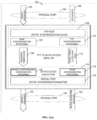
- FIG. 8 illustrates a block diagram of a device 800 that is suitable for implementing some example embodiments of the present disclosure.
- the device 800 can be used to implement, for example, the OLT 310 or the ONU 320 shown in FIG. 3 .
- the device 800 includes a processor 810 .
- the processor 810 controls operations and functions of the device 800 .
- the processor 810 may perform various operations by means of instructions 830 stored in the memory 820 coupled thereto.
- the memory 820 may be of any suitable type suitable for the local technical environment, and may be implemented using any suitable data storage technology, including but not limited to, a semiconductor-based storage device, a magnetic storage device and system, and an optical storage device and system. Although only one memory unit is shown in FIG. 8 , there may be multiple physically different memory units in the device 800 .
- the processor 810 may be of any suitable type suitable for the local technical environment, and may include, but is not limited to, general-purpose computers, special-purpose computers, microcontrollers, digital signal controllers (DSP), and one or more of controller-based multi-core controller architectures.
- the device 800 may also include multiple processors 810 .
- the processor 810 is coupled to the transceiver 840 which may receive and send information by means of optical fibers, cables, and/or other components.
- the processor 810 may implement the methods 400 and 500 described above with reference to FIGS. 3 to 5 by executing instructions. In a case where the device 800 acts as the ONU 320 , the processor 810 may implement the methods 600 and 700 described above with reference to FIGS. 6 and 7 by executing instructions. All the features described above with reference to FIG. 1 to FIG. 7 are applicable to the device 800 and will not be repeated herein.
- various example embodiments of the present disclosure may be implemented in hardware or special purpose circuits, software, logic, or any combination thereof. Some aspects may be implemented in hardware, while other aspects may be implemented in firmware or software that may be executed by a controller, microprocessor, or other computing devices. While the various aspects of the example embodiments of the present disclosure are illustrated and described as block diagrams, flowcharts, or using some other graphical representation, it is to be understood that the blocks, apparatuses, systems, techniques, or methods described herein can be regarded as non-limiting examples implemented in hardware, software, firmware, special purpose circuits or logic, general-purpose hardware or controllers or other computing devices, or some combination thereof.
- example embodiments of the present disclosure may be described in the context of machine-executable instructions, such as those included in program modules, being executed in a device on a target real or virtual processor.
- program modules include routines, programs, libraries, objects, classes, components, data structures, and etc., which perform particular tasks or implement specific abstract data types.
- the functionality of the program modules may be combined or split between the described program modules.
- the machine-executable instructions for the program modules may be executed within a local or distributed device. In a distributed device, program modules may be located in both local and remote storage media.
- the computer program codes for carrying out the methods of the present disclosure may be written in one or more programming languages.
- the computer program codes may be provided to a processor of a general purpose computer, a special purpose computer or other programmable data processing apparatus such that the program codes, when executed by the computer or other programmable data processing apparatus, cause the functions/operations specified in flowcharts and/or block diagrams to be implemented.
- the program codes may be executed entirely on a computer, partly on the computer, as a stand-alone software package, partly on the computer and partly on a remote computer or entirely on the remote computer or server.
- a machine-readable medium may be any tangible medium that includes or stores a program for use with or in connection with an instruction execution system, apparatus, or device.
- the computer-readable medium may be a machine-readable signal medium or a machine-readable storage medium.
- the computer-readable medium may include, but is not limited to, an electronic, magnetic, optical, electromagnetic, infrared, or semiconductor system, apparatus, or device, or any suitable combination of the foregoing.
- Computer-readable storage media would include electrical connections having one or more wires, a portable computer diskette, a hard disk, a random access memory (RAM), a read only memory (ROM), an erasable programmable read-only memory (EPROM or flash memory), an optical storage device, a magnetic storage device, or any suitable combination of the foregoing.
- RAM random access memory
- ROM read only memory
- EPROM erasable programmable read-only memory
- optical storage device a magnetic storage device, or any suitable combination of the foregoing.
- the optical line terminal comprising: at least one processor, and at least one memory having computer program codes stored thereon, the at least one memory and the computer program codes are configured to, with the at least one processor, cause the optical line terminal to: determine a threshold rate to be N messages per second for transmission of a time synchronization message to an optical network unit, N being greater than or equal to 0.1; and transmitting, to the optical network unit, the time synchronization message at the threshold rate or a rate above the threshold rate, to enable the optical network unit to perform time synchronization with the optical line terminal.
- the optical line terminal is further caused to: receive a reference clock phase signal for generation of the time synchronization message.
- the optical line terminal is caused to determine the threshold rate by: determining the threshold rate for the transmission of the time synchronization message based on an upper cutoff frequency of a noise signal of the reference clock phase signal.
- the reference clock phase signal is transmitted via a PTP packet
- the optical line terminal is caused to determine the threshold rate by: determining the threshold rate for the transmission of the time synchronization message based on a rate at which the optical line terminal receives a PTP event packet.
- the time synchronization message comprises ToD information.
- an optical network unit comprising: at least one processor, and at least one memory having computer program codes stored thereon, the at least one memory and the computer program codes are configured to, with the at least one processor, cause the optical network unit to: receive, from an optical line terminal, a time synchronization message at a threshold rate or a rate above the threshold rate, the threshold rate being N messages per second, N being an integer greater than or equal to 1; and perform time synchronization with the optical line terminal based on the time synchronization message.
- the time synchronization message is generated by the optical line terminal based on a reference clock phase signal.
- the threshold rate is associated with an upper cutoff frequency of a noise signal of the reference clock phase signal.
- the reference clock phase signal is transmitted via a PTP packet
- the threshold rate is associated with a rate at which the optical line terminal receives a PTP event packet.
- the time synchronization message comprises ToD information.
- the optical network unit is further caused to: complete processing of the received time synchronization message in 1/N of a second or a period less than 1/N of a second.
- an optical line terminal comprising: at least one processor, and at least one memory having computer program codes stored thereon, the at least one memory and the computer program codes are configured to, with the at least one processor, cause the optical line terminal to: select a plurality of optical network units for transmitting time synchronization information; and transmitting, to the plurality of optical network units, a broadcast or multicast message comprising the time synchronization information, to enable the plurality of optical network units to perform time synchronization with the optical line terminal.
- the broadcast or multicast message comprises at least one of a PLOAM message and an optical network unit OMCI message.
- the broadcast or multicast message comprises a group identifier for identifying the plurality of optical network units.
- the time synchronization information includes ToD information.
- an optical network unit comprising: at least one processor, and at least one memory having computer program codes stored thereon, the at least one memory and the computer program codes are configured to, with the at least one processor, cause the optical network unit to: receive, from an optical line terminal, a broadcast or multicast message comprising time synchronization information; and perform time synchronization with the optical line terminal based on the time synchronization information.
- the broadcast or multicast message comprises at least one of a PLOAM message and an optical network unit OMCI message.
- the broadcast or multicast message comprises a group identifier for identifying the plurality of optical network units.
- the time synchronization information comprises ToD information.
- the method implemented at an optical line terminal comprises: determining a threshold rate to be N messages per second for transmission of a time synchronization message to an optical network unit, N being greater than or equal to 0.1; and transmitting, to the optical network unit, the time synchronization message at the threshold rate or a rate above the threshold rate, to enable the optical network unit to perform time synchronization with the optical line terminal.
- the method further comprises: receiving a reference clock phase signal for generation of the time synchronization message.
- determining the threshold rate comprises:
- determining the threshold rate for the transmission of the time synchronization message based on an upper cutoff frequency of a noise signal of the reference clock phase signal.
- the reference clock phase signal is transmitted via a PTP packet
- determining the threshold rate comprises: determining the threshold rate for the transmission of the time synchronization message based on a rate at which the optical line terminal receives a PTP event packet.
- the time synchronization message comprises ToD information.
- a method implemented at an optical network unit comprising: receiving, from an optical line terminal, a time synchronization message at a threshold rate or a rate above the threshold rate, the threshold rate being N messages per second, N being greater than or equal to 0.1; and performing time synchronization with the optical line terminal based on the time synchronization message.
- the time synchronization message is generated by the optical line terminal based on a reference clock phase signal.
- the threshold rate is associated with an upper cutoff frequency of a noise signal of the reference clock phase signal.
- the reference clock phase signal is transmitted via a PTP packet
- the threshold rate is associated with a rate at which the optical line terminal receives a PTP event packet.
- the time synchronization message comprises ToD information.
- the method further comprises: completing processing of the received time synchronization message in 1/N of a second or a period less than 1/N of a second.
- a method implemented at an optical line terminal comprising: selecting a plurality of optical network units for transmitting time synchronization information; and transmitting, to the plurality of optical network units, a broadcast or multicast message comprising the time synchronization information, to enable the plurality of optical network units to perform time synchronization with the optical line terminal.
- the broadcast or multicast message comprises at least one of a PLOAM message and an optical network unit OMCI message.
- the broadcast or multicast message comprises a group identifier for identifying the plurality of optical network units.
- the time synchronization information comprises ToD information.
- a method implemented at an optical network unit comprising: receiving, from an optical line terminal, a broadcast or multicast message comprising time synchronization information; and performing time synchronization with the optical line terminal based on the time synchronization information.
- the broadcast or multicast message comprises at least one of a PLOAM message and an optical network unit OMCI message.
- the broadcast or multicast message comprises a group identifier for identifying the plurality of optical network units.
- the time synchronization information comprises ToD information.
- an apparatus comprising: means for determining a threshold rate to be N messages per second for transmission of a time synchronization message to an optical network unit, N being greater than or equal to 0.1; and means for transmitting, to the optical network unit, the time synchronization message at the threshold rate or a rate above the threshold rate, to enable the optical network unit to perform time synchronization with the optical line terminal.
- the apparatus further comprises: means for receiving a reference clock phase signal for generation of the time synchronization message.
- the means for determining the threshold rate comprises: means for determining the threshold rate for the transmission of the time synchronization message based on an upper cutoff frequency of a noise signal of the reference clock phase signal.
- the reference clock phase signal is transmitted via a PTP packet
- the means for determining the threshold rate comprises: means for determining the threshold rate for the transmission of the time synchronization message based on a rate at which the optical line terminal receives a PTP event packet.
- the time synchronization message comprises ToD information.
- an apparatus comprising: means for receiving, from an optical line terminal, a time synchronization message at a threshold rate or a rate above the threshold rate, the threshold rate being N messages per second, N being greater than or equal to 0.1; and means for performing time synchronization with the optical line terminal based on the time synchronization message.
- the time synchronization message is generated by the optical line terminal based on a reference clock phase signal.
- the threshold rate is associated with an upper cutoff frequency of a noise signal of the reference clock phase signal.
- the reference clock phase signal is transmitted via a
- the threshold rate is associated with a rate at which the optical line terminal receives a PTP event packet.
- the time synchronization message comprises ToD information.
- an apparatus comprising: means for selecting a plurality of optical network units for transmitting time synchronization information; and means for transmitting, to the plurality of optical network units, a broadcast or multicast message comprising the time synchronization information, to enable the plurality of optical network units to perform time synchronization with the optical line terminal.
- the broadcast or multicast message comprises at least one of a PLOAM message and an optical network unit OMCI message.
- the broadcast or multicast message comprises a group identifier for identifying the plurality of optical network units.
- the time synchronization information comprises ToD information.
- an apparatus comprising: means for receiving, from an optical line terminal, a broadcast or multicast message comprising time synchronization information; and means for performing time synchronization with the optical line terminal based on the time synchronization information.
- the broadcast or multicast message comprises at least one of a PLOAM message and an optical network unit OMCI message.
- the broadcast or multicast message comprises a group identifier for identifying the plurality of optical network units.
- the time synchronization information comprises ToD information.
- a computer-readable storage medium having program instructions stored thereon, the instructions, when executed by a processor on a device, cause the device to perform the method of some example embodiments of the present disclosure.
Abstract
Description
-
- The noise PTP-to-PTP and PTP-to-1PPS transfer of the output of the cascaded media converter equipment clock signal would have:
- A maximum gain of 0.2 dB,
- A maximum bandwidth of 0.1 Hz, and
- A minimum gain of −6 dB for frequencies less than or equal to 0.05 Hz.
N=0.1×4=0.4 pps (1)
In the case of using superframes for transmission of the ToD information, the threshold rate N is 0.4 superframes per second.
N=10×4=40 pps (2)
In the case of using superframes for transmission of the ToD information, the threshold rate N is 40 superframes per second. In order to satisfy the noise transfer of phase and frequency simultaneously, the threshold rate N should be 40 superframes per second on the basis of 4 times the sampling rate.
| TABLE 1 | ||
| Octet | Content | Descriptions |
| 1-2 | ONU-ID | 0x03FF, Broadcast ONU-ID. |
| 3 | Message type ID | 0xxx, “PLOAM message name”. |
| 4-7 | Superframe ID | the sequence number of the |
| specified GEM superframe. | ||
| 8-17 | The timestamp of | TstampN as defined in clause |
| Superframe | 10.4.6 of [ITU-T G.984.3], | |
| clause C 13.2 of [ITU-T G.9807.1] and | ||
| clause 13.2 of [ITU-T G.989.3], | ||
| using the timestamp format of | ||
| clause 5.3.3 of [IEEE 1588]. | ||
| 18-40 | Padding | Set to 0x00 by the transmitter; |
| treated as “don't care” by the | ||
| receiver. | ||
| 41-48 | MIC | Message integrity check (MIC), |
| computed using the default | ||
| PLOAM integrity key. | ||
-
- ToD message
- This message (ME) provides a way for the OLT to transmit the ToD information to the ONU.
- The ONU that supports this ME automatically creates an instance. After the startup phase, the OLT should periodically set the ONU to a desired value.
- Association
- A single instance of this ME is associated with a broadcast/multicast Gem port ID.
- Attributes
- Managed entity ID: This attribute uniquely identifies each instance of this ME. There is only one instance, numbered 0, (R) (mandatory) (2 bytes).
- ToD information: This attribute provides information required to achieve ToD synchronization between the reference clock on the OLT and the local clock on the ONU. This attribute includes two fields: the first field (4 bytes) is the sequence number of the specified GEM superframe. The second field (10 bytes) is TstampN, as defined in clause 10.4.6 of ITU-T G.984.3, clause 13.2 of ITU-T G.987.3 and clause 13.2 of ITU-T G.989.3, which utilizes the timestamp format as specified in clause 5.3.3 of IEEE 1588. The value 0 in all the bytes is reserved as a null value. (R, W) (optional) (14 bytes).
- Note: In the ITU-T G.987/ITU-T G.989 system, the superframe count field of the ToD information attribute includes 32 LSBs of the actual counter.
- Action
- obtain, set
- Notice
- None
- ToD message
Claims (15)
Applications Claiming Priority (2)
| Application Number | Priority Date | Filing Date | Title |
|---|---|---|---|
| CN201910944797.3 | 2019-09-30 | ||
| CN201910944797.3A CN112584260B (en) | 2019-09-30 | 2019-09-30 | Method, device, apparatus and medium for transmitting time synchronization message |
Publications (2)
| Publication Number | Publication Date |
|---|---|
| US20210099777A1 US20210099777A1 (en) | 2021-04-01 |
| US11595743B2 true US11595743B2 (en) | 2023-02-28 |
Family
ID=75117283
Family Applications (1)
| Application Number | Title | Priority Date | Filing Date |
|---|---|---|---|
| US17/036,507 Active US11595743B2 (en) | 2019-09-30 | 2020-09-29 | Methods, devices, apparatuses and computer storage media for transmission of a time synchronization message |
Country Status (2)
| Country | Link |
|---|---|
| US (1) | US11595743B2 (en) |
| CN (1) | CN112584260B (en) |
Citations (4)
| Publication number | Priority date | Publication date | Assignee | Title |
|---|---|---|---|---|
| US20100040369A1 (en) * | 2008-08-13 | 2010-02-18 | Jun Zhao | Time synchronization method and device in passive optical network and passive optical network |
| US20100098433A1 (en) * | 2008-10-21 | 2010-04-22 | Teknovus, Inc. | Synchronization transport over passive optical networks |
| US20100158527A1 (en) * | 2007-06-07 | 2010-06-24 | Hitachi, Ltd. | Optical communication system using wdma and cdma |
| US20120027414A1 (en) * | 2010-08-02 | 2012-02-02 | Futurewei Technologies, Inc. | Transparent Clocks in Access Networks |
Family Cites Families (4)
| Publication number | Priority date | Publication date | Assignee | Title |
|---|---|---|---|---|
| CN101552663B (en) * | 2008-04-02 | 2012-12-19 | 中兴通讯股份有限公司 | Passive optical network system and frequency and time synchronizing method thereof |
| CN101577600B (en) * | 2008-05-09 | 2013-04-24 | 华为技术有限公司 | Time synchronization method, system and optical network equipment for passive optical network system |
| CN102075238B (en) * | 2010-12-02 | 2015-04-01 | 中兴通讯股份有限公司 | Passive optical network and protection switching method thereof |
| CN110198197B (en) * | 2018-02-27 | 2020-11-17 | 浙江广欣网络科技有限公司 | Time synchronization method of Ethernet passive optical network and Ethernet passive optical network |
-
2019
- 2019-09-30 CN CN201910944797.3A patent/CN112584260B/en active Active
-
2020
- 2020-09-29 US US17/036,507 patent/US11595743B2/en active Active
Patent Citations (4)
| Publication number | Priority date | Publication date | Assignee | Title |
|---|---|---|---|---|
| US20100158527A1 (en) * | 2007-06-07 | 2010-06-24 | Hitachi, Ltd. | Optical communication system using wdma and cdma |
| US20100040369A1 (en) * | 2008-08-13 | 2010-02-18 | Jun Zhao | Time synchronization method and device in passive optical network and passive optical network |
| US20100098433A1 (en) * | 2008-10-21 | 2010-04-22 | Teknovus, Inc. | Synchronization transport over passive optical networks |
| US20120027414A1 (en) * | 2010-08-02 | 2012-02-02 | Futurewei Technologies, Inc. | Transparent Clocks in Access Networks |
Non-Patent Citations (1)
| Title |
|---|
| International Telecommunication Union, ITU-T G.8273.2, "Series G: Transmission Systems and Media, Digital Systems and Networks", Aug. 2019, 56 pgs. |
Also Published As
| Publication number | Publication date |
|---|---|
| CN112584260A (en) | 2021-03-30 |
| CN112584260B (en) | 2023-06-13 |
| US20210099777A1 (en) | 2021-04-01 |
Similar Documents
| Publication | Publication Date | Title |
|---|---|---|
| CN105075177B (en) | Downlink burst transmits in passive optical network | |
| JP5314768B2 (en) | Passive optical network system time synchronization method and synchronization system thereof | |
| CN109660311B (en) | Optical line terminal communication method and equipment with data structure | |
| US9025949B2 (en) | Equalization delay agnostic protection switching in protected passive optical networks | |
| US9071394B2 (en) | Remote timing communications | |
| US8600228B2 (en) | Optical communication | |
| JP4882614B2 (en) | Bit rate mixed optical communication method, optical subscriber unit and optical station side unit | |
| Han et al. | Development of efficient dynamic bandwidth allocation algorithm for XGPON | |
| US8953940B2 (en) | Method, apparatus, and system for time synchronization on passive optical network | |
| US8472801B2 (en) | Upgraded bandwidth map for ten gigabit passive optical network | |
| EP2862299B1 (en) | Time domains in a pon | |
| US10171227B2 (en) | Method and apparatus for configuring ONU as IEEE 1588 master clock in PON | |
| CN113556203B (en) | Time synchronization method in PON system, OLT, ONU and PON system | |
| CN108370271A (en) | Detection method, device and the passive optical network of optical network unit | |
| US11595743B2 (en) | Methods, devices, apparatuses and computer storage media for transmission of a time synchronization message | |
| CN110708135B (en) | Communication control system and method of passive optical network | |
| KR101679628B1 (en) | System and method for synchronizing precision time in passive optical network | |
| JP2018019378A (en) | Communication device, information notification method, and computer program | |
| CN102045602B (en) | Method, optical line terminal and optical network unit that frame is delimited | |
| CN108668183B (en) | Optical network synchronization test method and system | |
| JP2007189356A (en) | Burst bit synchronization circuit |
Legal Events
| Date | Code | Title | Description |
|---|---|---|---|
| FEPP | Fee payment procedure |
Free format text: ENTITY STATUS SET TO UNDISCOUNTED (ORIGINAL EVENT CODE: BIG.); ENTITY STATUS OF PATENT OWNER: LARGE ENTITY |
|
| AS | Assignment |
Owner name: NOKIA SHANGHAI BELL CO., LTD., CHINA Free format text: ASSIGNMENT OF ASSIGNORS INTEREST;ASSIGNORS:SUN, LIFEI;ZOU, JIABAO;GUO, SHENPING;AND OTHERS;REEL/FRAME:054015/0041 Effective date: 20191011 Owner name: NOKIA SOLUTIONS AND NETWORKS OY, FINLAND Free format text: ASSIGNMENT OF ASSIGNORS INTEREST;ASSIGNORS:SUN, LIFEI;ZOU, JIABAO;GUO, SHENPING;AND OTHERS;REEL/FRAME:054015/0041 Effective date: 20191011 |
|
| STPP | Information on status: patent application and granting procedure in general |
Free format text: APPLICATION DISPATCHED FROM PREEXAM, NOT YET DOCKETED |
|
| STPP | Information on status: patent application and granting procedure in general |
Free format text: DOCKETED NEW CASE - READY FOR EXAMINATION |
|
| STPP | Information on status: patent application and granting procedure in general |
Free format text: NON FINAL ACTION MAILED |
|
| STPP | Information on status: patent application and granting procedure in general |
Free format text: RESPONSE TO NON-FINAL OFFICE ACTION ENTERED AND FORWARDED TO EXAMINER |
|
| STPP | Information on status: patent application and granting procedure in general |
Free format text: FINAL REJECTION MAILED |
|
| STPP | Information on status: patent application and granting procedure in general |
Free format text: RESPONSE AFTER FINAL ACTION FORWARDED TO EXAMINER |
|
| STPP | Information on status: patent application and granting procedure in general |
Free format text: NOTICE OF ALLOWANCE MAILED -- APPLICATION RECEIVED IN OFFICE OF PUBLICATIONS |
|
| AS | Assignment |
Owner name: NOKIA TECHNOLOGIES OY, FINLAND Free format text: ASSIGNMENT OF ASSIGNORS INTEREST;ASSIGNORS:NOKIA SHANGHAI BELL CO., LTD.;NOKIA SOLUTIONS AND NETWORKS OY;REEL/FRAME:061369/0802 Effective date: 20220927 |
|
| STCB | Information on status: application discontinuation |
Free format text: ABANDONMENT FOR FAILURE TO CORRECT DRAWINGS/OATH/NONPUB REQUEST |
|
| STCF | Information on status: patent grant |
Free format text: PATENTED CASE |