US11595376B2 - Surveillance camera setting method, method of controlling an installation of a surveillance camera and surveillance camera system - Google Patents
Surveillance camera setting method, method of controlling an installation of a surveillance camera and surveillance camera system Download PDFInfo
- Publication number
- US11595376B2 US11595376B2 US15/446,717 US201715446717A US11595376B2 US 11595376 B2 US11595376 B2 US 11595376B2 US 201715446717 A US201715446717 A US 201715446717A US 11595376 B2 US11595376 B2 US 11595376B2
- Authority
- US
- United States
- Prior art keywords
- surveillance camera
- set value
- management device
- surveillance
- items
- Prior art date
- Legal status (The legal status is an assumption and is not a legal conclusion. Google has not performed a legal analysis and makes no representation as to the accuracy of the status listed.)
- Active, expires
Links
Images


Classifications
-
- H—ELECTRICITY
- H04—ELECTRIC COMMUNICATION TECHNIQUE
- H04L—TRANSMISSION OF DIGITAL INFORMATION, e.g. TELEGRAPHIC COMMUNICATION
- H04L63/00—Network architectures or network communication protocols for network security
- H04L63/08—Network architectures or network communication protocols for network security for authentication of entities
- H04L63/083—Network architectures or network communication protocols for network security for authentication of entities using passwords
-
- G—PHYSICS
- G01—MEASURING; TESTING
- G01S—RADIO DIRECTION-FINDING; RADIO NAVIGATION; DETERMINING DISTANCE OR VELOCITY BY USE OF RADIO WAVES; LOCATING OR PRESENCE-DETECTING BY USE OF THE REFLECTION OR RERADIATION OF RADIO WAVES; ANALOGOUS ARRANGEMENTS USING OTHER WAVES
- G01S19/00—Satellite radio beacon positioning systems; Determining position, velocity or attitude using signals transmitted by such systems
- G01S19/01—Satellite radio beacon positioning systems transmitting time-stamped messages, e.g. GPS [Global Positioning System], GLONASS [Global Orbiting Navigation Satellite System] or GALILEO
- G01S19/13—Receivers
-
- G—PHYSICS
- G06—COMPUTING; CALCULATING OR COUNTING
- G06F—ELECTRIC DIGITAL DATA PROCESSING
- G06F16/00—Information retrieval; Database structures therefor; File system structures therefor
- G06F16/80—Information retrieval; Database structures therefor; File system structures therefor of semi-structured data, e.g. markup language structured data such as SGML, XML or HTML
- G06F16/84—Mapping; Conversion
-
- G—PHYSICS
- G06—COMPUTING; CALCULATING OR COUNTING
- G06K—GRAPHICAL DATA READING; PRESENTATION OF DATA; RECORD CARRIERS; HANDLING RECORD CARRIERS
- G06K19/00—Record carriers for use with machines and with at least a part designed to carry digital markings
- G06K19/06—Record carriers for use with machines and with at least a part designed to carry digital markings characterised by the kind of the digital marking, e.g. shape, nature, code
- G06K19/06009—Record carriers for use with machines and with at least a part designed to carry digital markings characterised by the kind of the digital marking, e.g. shape, nature, code with optically detectable marking
- G06K19/06037—Record carriers for use with machines and with at least a part designed to carry digital markings characterised by the kind of the digital marking, e.g. shape, nature, code with optically detectable marking multi-dimensional coding
-
- G—PHYSICS
- G06—COMPUTING; CALCULATING OR COUNTING
- G06K—GRAPHICAL DATA READING; PRESENTATION OF DATA; RECORD CARRIERS; HANDLING RECORD CARRIERS
- G06K7/00—Methods or arrangements for sensing record carriers, e.g. for reading patterns
- G06K7/10—Methods or arrangements for sensing record carriers, e.g. for reading patterns by electromagnetic radiation, e.g. optical sensing; by corpuscular radiation
- G06K7/14—Methods or arrangements for sensing record carriers, e.g. for reading patterns by electromagnetic radiation, e.g. optical sensing; by corpuscular radiation using light without selection of wavelength, e.g. sensing reflected white light
- G06K7/1404—Methods for optical code recognition
- G06K7/1408—Methods for optical code recognition the method being specifically adapted for the type of code
- G06K7/1417—2D bar codes
-
- H—ELECTRICITY
- H04—ELECTRIC COMMUNICATION TECHNIQUE
- H04L—TRANSMISSION OF DIGITAL INFORMATION, e.g. TELEGRAPHIC COMMUNICATION
- H04L67/00—Network arrangements or protocols for supporting network services or applications
- H04L67/14—Session management
- H04L67/141—Setup of application sessions
-
- H—ELECTRICITY
- H04—ELECTRIC COMMUNICATION TECHNIQUE
- H04N—PICTORIAL COMMUNICATION, e.g. TELEVISION
- H04N23/00—Cameras or camera modules comprising electronic image sensors; Control thereof
- H04N23/60—Control of cameras or camera modules
- H04N23/66—Remote control of cameras or camera parts, e.g. by remote control devices
- H04N23/661—Transmitting camera control signals through networks, e.g. control via the Internet
-
- H—ELECTRICITY
- H04—ELECTRIC COMMUNICATION TECHNIQUE
- H04N—PICTORIAL COMMUNICATION, e.g. TELEVISION
- H04N7/00—Television systems
- H04N7/18—Closed-circuit television [CCTV] systems, i.e. systems in which the video signal is not broadcast
- H04N7/181—Closed-circuit television [CCTV] systems, i.e. systems in which the video signal is not broadcast for receiving images from a plurality of remote sources
-
- H—ELECTRICITY
- H04—ELECTRIC COMMUNICATION TECHNIQUE
- H04W—WIRELESS COMMUNICATION NETWORKS
- H04W12/00—Security arrangements; Authentication; Protecting privacy or anonymity
- H04W12/60—Context-dependent security
- H04W12/69—Identity-dependent
-
- H—ELECTRICITY
- H04—ELECTRIC COMMUNICATION TECHNIQUE
- H04W—WIRELESS COMMUNICATION NETWORKS
- H04W12/00—Security arrangements; Authentication; Protecting privacy or anonymity
- H04W12/60—Context-dependent security
- H04W12/69—Identity-dependent
- H04W12/77—Graphical identity
-
- G—PHYSICS
- G01—MEASURING; TESTING
- G01S—RADIO DIRECTION-FINDING; RADIO NAVIGATION; DETERMINING DISTANCE OR VELOCITY BY USE OF RADIO WAVES; LOCATING OR PRESENCE-DETECTING BY USE OF THE REFLECTION OR RERADIATION OF RADIO WAVES; ANALOGOUS ARRANGEMENTS USING OTHER WAVES
- G01S19/00—Satellite radio beacon positioning systems; Determining position, velocity or attitude using signals transmitted by such systems
- G01S19/38—Determining a navigation solution using signals transmitted by a satellite radio beacon positioning system
- G01S19/39—Determining a navigation solution using signals transmitted by a satellite radio beacon positioning system the satellite radio beacon positioning system transmitting time-stamped messages, e.g. GPS [Global Positioning System], GLONASS [Global Orbiting Navigation Satellite System] or GALILEO
- G01S19/42—Determining position
-
- H—ELECTRICITY
- H04—ELECTRIC COMMUNICATION TECHNIQUE
- H04N—PICTORIAL COMMUNICATION, e.g. TELEVISION
- H04N7/00—Television systems
- H04N7/18—Closed-circuit television [CCTV] systems, i.e. systems in which the video signal is not broadcast
- H04N7/183—Closed-circuit television [CCTV] systems, i.e. systems in which the video signal is not broadcast for receiving images from a single remote source
Definitions
- Exemplary embodiments relate to a surveillance camera setting method and a surveillance camera system.
- a surveillance camera system may include multiple surveillance cameras. To set specific set values for the surveillance cameras, users may generally have to set an access address for each of the surveillance cameras and access the surveillance cameras by using the set access addresses.
- Such an installation method may involve increased installation time with the increased number of surveillance cameras as well as increased time for maintenance thereof, as repeated checks on installation status and settings may be required for correct and exact installation.
- Exemplary embodiments include a surveillance camera setting method and a surveillance camera system that enable setting of surveillance cameras at the same time as the surveillance cameras are installed.
- Exemplary embodiments also include a surveillance camera configured to update a set value or set values of one or more set items by reading an object included in an image and configured to transmit the set value or set values in response to a set value transmission request from an external device.
- a surveillance camera configured to update a set value or set values of one or more set items by reading an object included in an image and configured to transmit the set value or set values in response to a set value transmission request from an external device.
- a method of setting a surveillance camera includes the steps of recognizing a readable object in an image captured by the surveillance camera, updating a set value of one or more set items of the surveillance camera associated with the readable object, and transmitting the set value of an at least one set item to an external device in response to receiving a request therefrom.
- the set value of the readable object may be in a visually recognizable form.
- the one or more set items may include at least one of an address of the surveillance camera in a network, an account for establishing connection to the surveillance camera from the at least one external device, a password for establishing connection to the surveillance camera from the at least one external device, and installation information on the surveillance camera.
- the readable object may include a quick response (QR) code.
- QR quick response
- the method may further include the step of checking whether the surveillance camera satisfies a first condition, in which the step of recognizing the readable object is performed when the first condition is satisfied.
- the first condition may be whether a time period from which the surveillance camera is powered on is within a first time range.
- the first condition may be whether the set value of the one or more set items is initialized.
- a method of controlling an installation of a surveillance camera includes the steps of detecting the surveillance camera connected to a network, generating mapping data of the detected surveillance camera, sending a request for a set value of one or more set items of the detected surveillance camera to the detected surveillance camera, receiving the set value from the detected surveillance camera, and updating the mapping data of the detected surveillance camera based on the received set value.
- a surveillance camera system includes at least one surveillance camera configured to update a set value of one or more set items by reading a readable object in a captured image, and transmit the set value of the one or more set items to an external device in response to receiving a request for the set value therefrom, a user terminal configured to display the readable object on a display based on at least one of user's input and a surveillance camera database, and a surveillance camera management device configured to send the request for the set value of the one or more set items to the at least one surveillance camera, and update mapping data of the at least one surveillance camera by receiving the set value from the at least one surveillance camera.
- the surveillance camera system may further include a network design device configured to set a connection relationship between the at least one surveillance camera and the network, and a set value of the at least one set item of the at least one surveillance camera according to a user's input.
- the network design device may be configured to generate the surveillance camera database including the set value of the at least one set item of the at least one surveillance camera.
- the installation information may include global positioning system (GPS) information with respect to a location of the at least one surveillance camera.
- GPS global positioning system
- FIG. 2 is a schematic view illustrating a surveillance camera according to an exemplary embodiment.
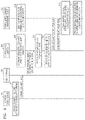
- FIG. 3 is a flowchart illustrating a method of processing information between elements of the surveillance camera system according to an exemplary embodiment.
- FIG. 5 is a view illustrating a screen for setting network connections using the network design device according to an exemplary embodiment.
- FIG. 7 is a view illustrating screens of a user terminal according to an exemplary embodiment.
- FIG. 8 is a view illustrating a screen of a surveillance camera management device according to an exemplary embodiment.
- FIG. 1 is a schematic view illustrating a surveillance camera system according to an exemplary embodiment.
- the user terminal 200 may be, for example, a personal computer (PC) or a portable terminal.
- the user terminal 200 is shown as a portable terminal including a display, such as a smartphone.
- any device capable of displaying a readable object based on at least one of a user's input and a surveillance camera database may be used as the user terminal 200 .
- the surveillance camera management device 300 may update mapping data of the surveillance camera 100 by requesting the surveillance camera 100 to send a set value or set values of one or more set items, and receiving the set value or set values of the one or more set items.
- the mapping data may be a data structure containing information about the surveillance camera 100 .
- the surveillance camera management device 300 may detect at least one surveillance camera connected to the network 500 and may create mapping data of the newly detected surveillance camera.
- the “newly detected surveillance camera” may be a surveillance camera in which mapping data thereof is not stored in the surveillance camera management device 300 , such as a surveillance camera newly connected to the network 500 .
- the surveillance camera management device 300 may have other functions, such as a function of receiving captured images from the surveillance camera 100 , a function of storing received images, and/or a function of providing stored images to a user in response to a user's request.
- the surveillance camera management device 300 may include, for example, one or more of a video management system (VMS), a content management system (CMS), a network video recorder (NVR), and a digital video recorder (DVR), to facilitate the above-described functions.
- VMS video management system
- CMS content management system
- NVR network video recorder
- DVR digital video recorder
- the network design device 400 may perform the above-described setting operations before the surveillance camera system is installed.
- a user may perform the above-described setting operations using the network design device 400 before the surveillance camera system is installed, so as to virtually configure the surveillance camera system in advance and check whether the surveillance camera system has errors, stability in operation, etc.
- the network design device 400 may create a database including a set value of at least one of set items of a surveillance camera based on the above-described settings.
- the database generated may be provided to the user terminal 200 , and a user may use the database when the user installs a surveillance camera using the user terminal 200 . More particularly, when a user actually installs a surveillance camera, the user may update set values of the surveillance camera using a database, which is created based on connection settings and set items input into the network design device 400 during a system design stage.
- the surveillance camera 100 may recognize and/or read a readable object included in a captured image so as to update a set value or set values of one or more set items.
- the surveillance camera 100 may receive a request for a set value or set values of one or more set items from at least one external device, and may send the set value or set values of the one or more set items to the at least one external device upon receiving the request.
- the external device may be the surveillance camera management device 300 , for example.
- FIG. 2 is a schematic view illustrating the surveillance camera 100 according to an exemplary embodiment.
- the optical unit 110 may include a lens and an image sensor, and may convert light into an electric signal.
- the optical unit 110 may include a lens group including at least one lens.
- the image sensor may convert images input through the lens into electric signals.
- the image sensor may be a semiconductor device such as a charge-coupled device (CCD) or a complementary metal oxide semiconductor (CMOS) device capable of converting optical signals, such as images, into electric signals.
- CCD charge-coupled device
- CMOS complementary metal oxide semiconductor
- the controller 130 may include any kind of devices, such as a processor, that may be capable of processing data.
- a processor may refer to a data processing device included in a hardware and having a physically structured circuit to execute codes of programs or functions expressed with instructions. Examples of the data processing device included in a hardware may include a microprocessor, a central processing unit (CPU), a processor core, a multiprocessor, an application-specific integrated circuit (ASIC), and a field programmable gate array (FPGA).
- CPU central processing unit
- ASIC application-specific integrated circuit
- FPGA field programmable gate array
- the memory 140 may temporarily or permanently store data, instructions, programs, program codes, or combinations thereof that the controller 130 processes.
- the memory 140 may include, for example, a magnetic storage medium and/or a flash storage medium.
- the memory 140 may temporarily or permanently store a set value or set values for one or more set items of the surveillance camera 100 in addition to data and instructions, and may also temporarily or permanently store images captured by the surveillance camera 100 .
- the “particular condition” may be whether a time period from which the surveillance camera 100 has been powered on is within a preset critical time range.
- the controller 130 may determine that the surveillance camera 100 satisfies the particular condition when the surveillance camera 100 has been powered on within the last 1000 seconds.
- the controller 130 may recognize a readable object included in an image captured by the surveillance camera 100 .
- the term “object” may refer to an object in which a set value or set values for one or more set items of the surveillance camera 100 are included in a visually recognizable form.
- an object may be one of a quick response (QR) code or a bar code. It is contemplated that, however, any object having a shape, in which a set value or set values for one or more set items of the surveillance camera 100 are included in a visually recognizable form, may be used as the object.
- an object may be a character string denoting a set value or set values for one or more set items of the surveillance camera 100 .
- “one or more set items of the surveillance camera 100 ” may be an item or items that may not be set by a user, such as the model name or MAC address of the surveillance camera 100 . It is contemplated that, however, any item denoting a property of the surveillance camera 100 may be a set item according to exemplary embodiments.
- the expression “recognizing a readable object included in an image” may be referred to as the controller 130 identifying a recognizable object in an image.
- the expression “recognizing a readable object included in an image” may refer that the controller 130 identifies the QR code in the image.
- the controller 130 may read a recognized object and may update a set value or set values of one or more set items of the surveillance camera 100 .
- an “object” may include a set value or set values for one or more set items of the surveillance camera 100 in a visually recognizable form, and thus, the controller 130 may obtain information about a set value or set values by reading the object.
- the controller 130 may obtain set values such as an address “192.168.10.10” of the surveillance camera 100 in the network 500 and an account “admin” for establishing connection to the surveillance camera 100 , and may update a set value or set values of one or more set items based on the obtained set values.
- the surveillance camera 100 may photograph an object as described above, a user may rapidly and simply update set values of multiple set items of the surveillance camera 100 .
- the controller 130 may receive a request for a set value of at least one set item, among a set value or set values of one or more set items, from at least one external device. In addition, the controller 130 may send the set value of the at least one set item to the at least one external device in response to receiving the request for the set value received from the at least one external device.
- the controller 130 may receive a request from an external device such as the surveillance camera management device 300 for an address of the surveillance camera 100 in the network 500 , an account for establishing connection to the surveillance camera 100 from the surveillance camera management device 300 , a password for establishing connection to the surveillance camera 100 from the surveillance camera management device 300 , and a set value for a set item of the surveillance camera 100 . Then, the controller 130 may send set values for set items corresponding to the request to the surveillance camera management device 300 .
- an external device such as the surveillance camera management device 300 for an address of the surveillance camera 100 in the network 500 , an account for establishing connection to the surveillance camera 100 from the surveillance camera management device 300 , a password for establishing connection to the surveillance camera 100 from the surveillance camera management device 300 , and a set value for a set item of the surveillance camera 100 .
- a user when a user installs a surveillance camera system, a user may typically have to carry out cumbersome procedures such as setting address of each surveillance camera and checking images sent from the respective surveillance cameras.
- cumbersome procedures such as setting address of each surveillance camera and checking images sent from the respective surveillance cameras.
- multiple surveillance cameras of the same model are included in a surveillance camera system, it may be difficult to distinguish the surveillance cameras by using the model name alone, and thus, a user may have to perform several conformation procedures to distinguish between the surveillance cameras.
- a conventional surveillance camera to be installed at a specific position may be previously designated, and after individually setting surveillance cameras according to installation positions, the designated surveillance camera may be installed at the specific position.
- a designated surveillance camera should be installed at a specific position according to conventional methods, and thus, it would take much time to arrange surveillance cameras and find the designated surveillance camera.
- the surveillance cameras may capture images of objects, by which set items of the surveillance cameras may be simply changed.
- the set items of the surveillance cameras may be precisely checked using an external device such as the surveillance camera management device 300 .
- set items of surveillance cameras may be immediately changed while the surveillance cameras are installed, and thus, any one of the surveillance cameras may be installed at any position without positional limitations as long as the surveillance cameras are of the same model, thereby reducing time and costs associated with the installation process.
- individually inputting set items of the surveillance cameras may be obviated, and thus, the surveillance camera system may be effectively installed.
- FIG. 3 is a flowchart illustrating a method of processing information between elements of the surveillance camera system according to an exemplary embodiment.
- the network design device 400 may create a database including a set value of at least one of set items of at least one surveillance camera (S 31 ). As described above, the network design device 400 may set a network connection relationship regarding at least one surveillance camera, and a set value or set values of one or more set items of the at least one surveillance camera according to a user's input. In addition, the network design device 400 may create a database including a set value of at least one of set items of the at least one surveillance camera based on the above-described settings.
- the network design device 400 may transmit the database to the user terminal 200 (S 32 ). In this case, the network design device 400 may send the database to the user terminal 200 using the network 500 , another network (not shown), or any other communication method.
- the surveillance camera 100 may determine whether the state of the surveillance camera 100 satisfies a particular condition (S 33 ).
- the surveillance camera 100 may perform an object recognizing operation at step S 36 , only when the state of the surveillance camera 100 satisfies the particular condition at step S 33 .
- the “particular condition” may be whether a time period from which the surveillance camera 100 is powered on is within a preset critical time range. For example, it may be determined that the surveillance camera 100 satisfies the particular condition when the surveillance camera 100 has been powered on within last 1000 seconds.
- the “particular condition” may alternatively or additionally be a condition in which all set values of one or more set items of the surveillance camera 100 have not been set. For example, if set values of all set items of the surveillance camera 100 are initialized into a non-set state using the reset button (not shown) of the surveillance camera 100 , it may be determined that the surveillance camera 100 satisfies the particular condition at step S 33 .
- the surveillance camera 100 performs the object recognizing operation at step S 36 only when the state of the surveillance camera 100 satisfies the particular condition, resources of the surveillance camera 100 may be effectively used, and malfunctioning of the surveillance camera 100 may be prevented.
- the surveillance camera management device 300 may detect at least one surveillance camera connected to the network 500 and may create mapping data of the newly detected surveillance camera (S 34 ).
- the “newly detected surveillance camera” may be a surveillance camera of which mapping data thereof is not stored in the surveillance camera management device 300 , such as a surveillance camera newly connected to the network 500 . Thereafter, the surveillance camera management device 300 may request the newly detected surveillance camera 100 to send a set value or set values of one or more set items thereof.
- the user terminal 200 may display a readable object on the display of the user terminal 200 based on the database received from the network design device 400 and a user's input (S 35 ).
- step S 33 if the state of the surveillance camera 100 is determined as satisfying the particular condition, the surveillance camera 100 may recognize the readable object included in an image captured by the surveillance camera 100 (S 36 ).
- the “object” may refer to an object having a shape in which a set value or set values for one or more set items of the surveillance camera 100 are included in a visually recognizable form.
- the expression “recognizing a readable object included in an image” may be referred as to the controller 130 identifying a recognizable object in an image.
- the expression “recognizing a readable object included in an image” may refer that the controller 130 identifies the QR code included in the image.
- the surveillance camera 100 may read the readable object and update a set value or set values of one or more set items of the surveillance camera 100 (S 37 ). For example, if an object is a QR code and set items of the surveillance camera 100 are an address of the surveillance camera 100 in the network 500 and an account for connecting to the surveillance camera 100 from an external device, the controller 130 may obtain set values such as an address “192.168.10.10” of the surveillance camera 100 in the network 500 and an account “admin” for establishing connection to the surveillance camera 100 , and may update a set value or set values of one or more set items. In this manner, since the surveillance camera 100 may photograph an object as described above, a user may rapidly and simply update set values of set items of the surveillance camera 100 .
- the surveillance camera 100 may receive a request for a set value of at least one set item among a set value or set values of one or more set items from the surveillance camera management device 300 (S 38 ). The surveillance camera 100 may then send the set value of the at least one set item to the surveillance camera management device 300 in response to receiving the request (S 39 ).
- the surveillance camera 100 may receive a request from the surveillance camera management device 300 for an address of the surveillance camera 100 in the network 500 , an account for establishing connection to the surveillance camera 100 from an external device, a password for establishing connection to the surveillance camera 100 from an external device, and a set value of a set item of the surveillance camera 100 . Then, the surveillance camera 100 may send set values of set items corresponding to the request to the surveillance camera management device 300 .
- the surveillance camera management device 300 may update mapping data of the surveillance camera 100 based on a set value of at least one set item received from the surveillance camera 100 (S 40 ).
- the surveillance camera management device 300 may provide installation information on the surveillance camera 100 to a user based on the updated mapping data (S 41 ).
- FIGS. 4 to 8 are views illustrating processes of installing a surveillance camera system according to exemplary embodiments.
- FIG. 4 is a view illustrating the surveillance camera system installed according to an exemplary embodiment.
- the surveillance cameras 41 to 47 may recognize objects such as QR codes at the same time a user installs the surveillance camera management device 300 and the surveillance cameras 41 to 47 . In this manner, installation and setting of the surveillance cameras 41 to 47 may be completed at one time. More particularly, in the case shown in FIG. 4 , a user may complete the installation of the surveillance camera system by moving once along a path 40 . As described above, according to an exemplary embodiment, the surveillance camera system may be efficiently installed in a precise and rapid manner.
- FIG. 5 is a view illustrating a screen 50 for setting network connections using a network design device 400 according to an exemplary embodiment.
- the screen 50 may include a taskpad 51 for network design and a window 52 displaying elements that may be added to the taskpad 51 .
- a user may virtually configure a system using the network design device 400 before installing a surveillance camera system, so as to check system errors, the number of necessary elements, operational stability, etc.
- a user may add elements of a surveillance camera system to the taskpad 51 and may set a connection relationship between the elements. At this time, the user may select elements of the surveillance camera system such as surveillance cameras, check set items of the elements, and input set values for the set items.
- the network design device 400 may create a database including a set value for at least one of set items of a surveillance camera based on a surveillance camera system that has been configured via the taskpad 51 .
- FIG. 6 is a view including a database created by the network design device 400 according to an exemplary embodiment.
- the database may include a set value for at least one of set items of one or more surveillance cameras.
- the database may include a surveillance camera installation information item 61 in addition to an address of at least one surveillance camera in a network, an account for establishing connection to the at least one surveillance camera from an external device, and a password for establishing connection to the at least one surveillance camera from an external device.
- the surveillance camera installation information item 61 and the other items may be converted into a visually recognizable form such as a QR code by a user terminal 200 , and may then be input into a surveillance camera.
- a user may virtually configure a system using the network design device 400 and may create a database based on the virtually configured system.
- the database created may be transmitted to the user terminal 200 , and the user terminal 200 may convert information about each surveillance camera into a visually recognizable form such as a QR code, such that a set value for each set item of the surveillance camera may be input.
- FIG. 7 illustrates screens 71 and 72 of the user terminal 200 according to an exemplary embodiment.
- the user terminal 200 may display a database 711 generated by the network design device 400 .
- a user may roughly figure out a system by referring to the database 711 displayed on the screen 71 .
- a user may start system installation by touching a begin setup button 712 .
- the user terminal 200 may display a QR code 721 and a detailed description 722 of the QR code 721 as shown in the screen 72 based on set values of at least one surveillance camera included in the database 711 .
- a user may immediately complete setting of the surveillance camera by taking a picture of the QR code 721 displayed on the screen 72 by using the surveillance camera.
- a user may return to a screen for the previous surveillance camera, or may move on to a screen for the next surveillance camera or a list screen, such as the screen 71 , by using a manipulation button 723 .
- FIG. 8 is a view illustrating a screen 80 of a surveillance camera management device 300 according to an exemplary embodiment.
- the screen 80 may include a window 81 displaying surveillance cameras connected to a network, a window 82 displaying detailed information about a selected surveillance camera, and a window 83 showing the location of the selected surveillance camera.
- the user may complete setting of the surveillance camera by taking a picture of a QR code displayed on a screen of the user terminal 200 by using the surveillance camera. In this manner, a user may check installed surveillance cameras using the surveillance camera management device 300 without any additional setting operation.
- the window 82 of the surveillance camera management device 300 may display detailed information about the first main room camera 811 and real time images 821 captured by the first main room camera 811 , and the window 83 may display the location 831 of the first main room camera 811 .
- non-transitory computer readable media may include: magnetic media such as hard disks, floppy disks, and magnetic tapes; optical recording media such as CD-ROMs and DVDs; magneto-optical media such as floptical disks; and hardware such as ROMs, RAMs, and flash memories specifically configured to store program instructions and execute the program instructions.
- Examples of the non-transitory computer readable media may include intangible media that may be transferred over network.
- the non-transitory computer readable media may be implemented in the form of software or applications that may also be transferred and distributed over network.
- the computer programs may be those designed and configured according to the embodiments or well known in the computer software industry.
- Examples of the computer programs may include machine codes made by compilers and high-level language codes executable on computers using interpreters.
- connection lines or members between elements are exemplary functional, physical, and/or electric connections that may be replaced with or used together with other functional, physical, and/or electrical connections. Elements described without using terms such as “essential” and “important” may not be necessary for constituting the inventive concept.
- one or more exemplary embodiments may provide a surveillance camera setting method and a surveillance camera system that may provide setting of surveillance cameras at the same time as the surveillance cameras are installed.
- one or more exemplary embodiments may provide a surveillance camera configured to update a set value or set values of one or more set items by reading an object included in an image and configured to transmit the set value or set values in response to a set value transmission request from an external device.
- one or more exemplary embodiments may provide a user terminal that may display an object for setting a surveillance camera by receiving a database from a network design device.
- one or more exemplary embodiments may provide a surveillance camera management device configured to send a request for a set value or set values to a surveillance camera and update mapping data of the surveillance camera by receiving the set value or set values from the surveillance camera.
Abstract
Description
Claims (14)
Applications Claiming Priority (2)
| Application Number | Priority Date | Filing Date | Title |
|---|---|---|---|
| KR10-2016-0108382 | 2016-08-25 | ||
| KR1020160108382A KR102568996B1 (en) | 2016-08-25 | 2016-08-25 | Surveillance camera setting method, method and system for surveillance camera management |
Publications (2)
| Publication Number | Publication Date |
|---|---|
| US20180063120A1 US20180063120A1 (en) | 2018-03-01 |
| US11595376B2 true US11595376B2 (en) | 2023-02-28 |
Family
ID=61243968
Family Applications (1)
| Application Number | Title | Priority Date | Filing Date |
|---|---|---|---|
| US15/446,717 Active 2037-10-29 US11595376B2 (en) | 2016-08-25 | 2017-03-01 | Surveillance camera setting method, method of controlling an installation of a surveillance camera and surveillance camera system |
Country Status (2)
| Country | Link |
|---|---|
| US (1) | US11595376B2 (en) |
| KR (1) | KR102568996B1 (en) |
Families Citing this family (5)
| Publication number | Priority date | Publication date | Assignee | Title |
|---|---|---|---|---|
| CN108712631A (en) * | 2018-04-27 | 2018-10-26 | 宁夏佳圣工贸有限公司 | A kind of monitoring system based on Internet of Things |
| CN111600732B (en) * | 2019-02-20 | 2023-06-20 | 浙江宇视科技有限公司 | Method and device for automatically activating and adding front-end equipment by front-end management equipment |
| KR102029855B1 (en) * | 2019-07-09 | 2019-10-08 | 주형진 | Video surveillance apparatus supporting optimization for operating environment of camera and operating method of the same |
| US11190737B2 (en) | 2020-04-30 | 2021-11-30 | Genetec Inc. | Method and system for identifying a video camera of a video surveillance environment |
| US20230300447A1 (en) * | 2022-03-18 | 2023-09-21 | Johnson Controls Tyco IP Holdings LLP | Systems and methods for camera configuration |
Citations (14)
| Publication number | Priority date | Publication date | Assignee | Title |
|---|---|---|---|---|
| US20080198159A1 (en) * | 2007-02-16 | 2008-08-21 | Matsushita Electric Industrial Co., Ltd. | Method and apparatus for efficient and flexible surveillance visualization with context sensitive privacy preserving and power lens data mining |
| US20110317016A1 (en) * | 2010-06-28 | 2011-12-29 | Takashi Saeki | Camera layout determination support device |
| US20130120571A1 (en) * | 2011-11-14 | 2013-05-16 | Itx Security Co., Ltd. | Security camera and method for controlling auto-focusing of the same |
| US20130169801A1 (en) * | 2011-12-28 | 2013-07-04 | Pelco, Inc. | Visual Command Processing |
| KR101386591B1 (en) | 2012-09-13 | 2014-04-28 | 서울특별시 성동구 | CCTV integrated management system |
| KR20140109108A (en) | 2013-03-05 | 2014-09-15 | 유넷시스템주식회사 | Network automatic connecting method using qr code |
| KR20140124289A (en) | 2013-04-16 | 2014-10-24 | 삼성테크윈 주식회사 | Method for controlling surveillance camera |
| KR20150074309A (en) * | 2013-12-23 | 2015-07-02 | 주식회사 케이티 | Management server, registration terminal and method for registering installation position of surveillance camera |
| KR20160054930A (en) | 2014-11-07 | 2016-05-17 | 현대모비스 주식회사 | Pattern-detect AVM system |
| US20160343137A1 (en) * | 2015-05-19 | 2016-11-24 | Axis Ab | Method and system for determining spatial characteristics of a camera |
| US20170200356A1 (en) * | 2014-06-11 | 2017-07-13 | San Kim | Surveillance camera capable of outputting video and video transmission/reception system including same |
| US20170278365A1 (en) * | 2016-03-22 | 2017-09-28 | Tyco International Management Company | System and method for configuring surveillance cameras using mobile computing devices |
| US20170278367A1 (en) * | 2016-03-22 | 2017-09-28 | Tyco International Management Company | System and method for overlap detection in surveillance camera network |
| US20180270763A1 (en) * | 2016-01-11 | 2018-09-20 | Hanwha Techwin Co., Ltd. | Surveillance system and method of controlling the same |
Family Cites Families (3)
| Publication number | Priority date | Publication date | Assignee | Title |
|---|---|---|---|---|
| JP2010114584A (en) * | 2008-11-05 | 2010-05-20 | Mitsubishi Electric Corp | Camera device |
| US20140211018A1 (en) * | 2013-01-29 | 2014-07-31 | Hewlett-Packard Development Company, L.P. | Device configuration with machine-readable identifiers |
| EP3487342A2 (en) * | 2016-07-21 | 2019-05-29 | NIKE Innovate C.V. | Article of footwear with multiple layers, retention system for an article of footwear, and methods of manufacture |
-
2016
- 2016-08-25 KR KR1020160108382A patent/KR102568996B1/en active IP Right Grant
-
2017
- 2017-03-01 US US15/446,717 patent/US11595376B2/en active Active
Patent Citations (14)
| Publication number | Priority date | Publication date | Assignee | Title |
|---|---|---|---|---|
| US20080198159A1 (en) * | 2007-02-16 | 2008-08-21 | Matsushita Electric Industrial Co., Ltd. | Method and apparatus for efficient and flexible surveillance visualization with context sensitive privacy preserving and power lens data mining |
| US20110317016A1 (en) * | 2010-06-28 | 2011-12-29 | Takashi Saeki | Camera layout determination support device |
| US20130120571A1 (en) * | 2011-11-14 | 2013-05-16 | Itx Security Co., Ltd. | Security camera and method for controlling auto-focusing of the same |
| US20130169801A1 (en) * | 2011-12-28 | 2013-07-04 | Pelco, Inc. | Visual Command Processing |
| KR101386591B1 (en) | 2012-09-13 | 2014-04-28 | 서울특별시 성동구 | CCTV integrated management system |
| KR20140109108A (en) | 2013-03-05 | 2014-09-15 | 유넷시스템주식회사 | Network automatic connecting method using qr code |
| KR20140124289A (en) | 2013-04-16 | 2014-10-24 | 삼성테크윈 주식회사 | Method for controlling surveillance camera |
| KR20150074309A (en) * | 2013-12-23 | 2015-07-02 | 주식회사 케이티 | Management server, registration terminal and method for registering installation position of surveillance camera |
| US20170200356A1 (en) * | 2014-06-11 | 2017-07-13 | San Kim | Surveillance camera capable of outputting video and video transmission/reception system including same |
| KR20160054930A (en) | 2014-11-07 | 2016-05-17 | 현대모비스 주식회사 | Pattern-detect AVM system |
| US20160343137A1 (en) * | 2015-05-19 | 2016-11-24 | Axis Ab | Method and system for determining spatial characteristics of a camera |
| US20180270763A1 (en) * | 2016-01-11 | 2018-09-20 | Hanwha Techwin Co., Ltd. | Surveillance system and method of controlling the same |
| US20170278365A1 (en) * | 2016-03-22 | 2017-09-28 | Tyco International Management Company | System and method for configuring surveillance cameras using mobile computing devices |
| US20170278367A1 (en) * | 2016-03-22 | 2017-09-28 | Tyco International Management Company | System and method for overlap detection in surveillance camera network |
Also Published As
| Publication number | Publication date |
|---|---|
| KR20180023300A (en) | 2018-03-07 |
| US20180063120A1 (en) | 2018-03-01 |
| KR102568996B1 (en) | 2023-08-21 |
Similar Documents
| Publication | Publication Date | Title |
|---|---|---|
| US11595376B2 (en) | Surveillance camera setting method, method of controlling an installation of a surveillance camera and surveillance camera system | |
| US9911002B2 (en) | Method of modifying image including photographing restricted element, and device and system for performing the method | |
| EP3287866A1 (en) | Electronic device and method of providing image acquired by image sensor to application | |
| CN105308648A (en) | Systems and methods to super resolve a user-selected region of interest | |
| CN103167258B (en) | For selecting the method for the image that image capture apparatus is caught, system and equipment | |
| US20170324893A1 (en) | Network system and control method for network system | |
| US20160286134A1 (en) | Method for configuring a camera | |
| JP7367812B2 (en) | Information processing system, information processing method and program | |
| CN106537799A (en) | Camera control and image streaming | |
| WO2020098431A1 (en) | Method and device for establishing map model | |
| US20200014591A1 (en) | Method and system of device deployment integrating with automatic configuration and asset management | |
| JP6620232B2 (en) | Technology for attaching media captured by a mobile computing device to an electronic document | |
| US11811976B2 (en) | Information processing system to obtain and manage images of a property | |
| US9179056B2 (en) | Image capturing systems with context control and related methods | |
| US20170195129A1 (en) | Method and device to control secondary devices | |
| US20180012410A1 (en) | Display control method and device | |
| US20170126951A1 (en) | Updating an exposure table of an image sensor | |
| US10754663B2 (en) | Dynamic determination of hardware | |
| JP5891828B2 (en) | Mobile terminal, photographed image disclosure method, program | |
| JP7279416B2 (en) | Intermediary terminal, communication system, input system, intermediary control method, and program | |
| JP6026703B2 (en) | Router access control method, apparatus, router, program, and recording medium | |
| KR102154434B1 (en) | Apparatus for capturing an image and operating method thereof | |
| US9247419B2 (en) | Communication apparatus, information processing apparatus, control methods therefor, and system | |
| KR102264185B1 (en) | SYSTEM and METHOD FOR controling multiple drone camera and video proccessing | |
| US11163856B2 (en) | Offline license activation for barcode decoders |
Legal Events
| Date | Code | Title | Description |
|---|---|---|---|
| AS | Assignment |
Owner name: HANWHA TECHWIN CO., LTD., KOREA, REPUBLIC OF Free format text: ASSIGNMENT OF ASSIGNORS INTEREST;ASSIGNORS:KIM, HYUN HO;KIM, KYUNG DUK;SHIM, MIN JUNG;REEL/FRAME:041425/0791 Effective date: 20170227 |
|
| AS | Assignment |
Owner name: HANWHA AEROSPACE CO., LTD., KOREA, REPUBLIC OF Free format text: CHANGE OF NAME;ASSIGNOR:HANWHA TECHWIN CO., LTD;REEL/FRAME:046927/0019 Effective date: 20180401 |
|
| AS | Assignment |
Owner name: HANWHA AEROSPACE CO., LTD., KOREA, REPUBLIC OF Free format text: CORRECTIVE ASSIGNMENT TO CORRECT THE APPLICATION NUMBER 10/853,669. IN ADDITION PLEASE SEE EXHIBIT A PREVIOUSLY RECORDED ON REEL 046927 FRAME 0019. ASSIGNOR(S) HEREBY CONFIRMS THE CHANGE OF NAME;ASSIGNOR:HANWHA TECHWIN CO., LTD.;REEL/FRAME:048496/0596 Effective date: 20180401 |
|
| STPP | Information on status: patent application and granting procedure in general |
Free format text: RESPONSE TO NON-FINAL OFFICE ACTION ENTERED AND FORWARDED TO EXAMINER |
|
| AS | Assignment |
Owner name: HANWHA TECHWIN CO., LTD., KOREA, REPUBLIC OF Free format text: ASSIGNMENT OF ASSIGNORS INTEREST;ASSIGNOR:HANWHA AEROSPACE CO., LTD.;REEL/FRAME:049013/0723 Effective date: 20190417 |
|
| STPP | Information on status: patent application and granting procedure in general |
Free format text: FINAL REJECTION MAILED |
|
| STPP | Information on status: patent application and granting procedure in general |
Free format text: ADVISORY ACTION MAILED |
|
| STCV | Information on status: appeal procedure |
Free format text: NOTICE OF APPEAL FILED |
|
| STCV | Information on status: appeal procedure |
Free format text: APPEAL BRIEF (OR SUPPLEMENTAL BRIEF) ENTERED AND FORWARDED TO EXAMINER |
|
| STCV | Information on status: appeal procedure |
Free format text: EXAMINER'S ANSWER TO APPEAL BRIEF MAILED |
|
| STCV | Information on status: appeal procedure |
Free format text: ON APPEAL -- AWAITING DECISION BY THE BOARD OF APPEALS |
|
| STCV | Information on status: appeal procedure |
Free format text: REQUEST RECONSIDERATION AFTER BOARD OF APPEALS DECISION |
|
| STCV | Information on status: appeal procedure |
Free format text: BOARD OF APPEALS DECISION RENDERED AFTER REQUEST FOR RECONSIDERATION |
|
| STPP | Information on status: patent application and granting procedure in general |
Free format text: DOCKETED NEW CASE - READY FOR EXAMINATION |
|
| STPP | Information on status: patent application and granting procedure in general |
Free format text: NON FINAL ACTION MAILED |
|
| STPP | Information on status: patent application and granting procedure in general |
Free format text: RESPONSE TO NON-FINAL OFFICE ACTION ENTERED AND FORWARDED TO EXAMINER |
|
| STPP | Information on status: patent application and granting procedure in general |
Free format text: FINAL REJECTION MAILED |
|
| STPP | Information on status: patent application and granting procedure in general |
Free format text: RESPONSE AFTER FINAL ACTION FORWARDED TO EXAMINER |
|
| STPP | Information on status: patent application and granting procedure in general |
Free format text: ADVISORY ACTION MAILED |
|
| STPP | Information on status: patent application and granting procedure in general |
Free format text: RESPONSE TO NON-FINAL OFFICE ACTION ENTERED AND FORWARDED TO EXAMINER |
|
| STPP | Information on status: patent application and granting procedure in general |
Free format text: NOTICE OF ALLOWANCE MAILED -- APPLICATION RECEIVED IN OFFICE OF PUBLICATIONS |
|
| STPP | Information on status: patent application and granting procedure in general |
Free format text: AWAITING TC RESP., ISSUE FEE NOT PAID |
|
| STPP | Information on status: patent application and granting procedure in general |
Free format text: NOTICE OF ALLOWANCE MAILED -- APPLICATION RECEIVED IN OFFICE OF PUBLICATIONS |
|
| STCF | Information on status: patent grant |
Free format text: PATENTED CASE |
|
| AS | Assignment |
Owner name: HANWHA VISION CO., LTD., KOREA, REPUBLIC OF Free format text: CHANGE OF NAME;ASSIGNOR:HANWHA TECHWIN CO., LTD.;REEL/FRAME:064549/0075 Effective date: 20230228 |