US11592624B2 - Fiber optic micro connector - Google Patents
Fiber optic micro connector Download PDFInfo
- Publication number
- US11592624B2 US11592624B2 US17/196,683 US202117196683A US11592624B2 US 11592624 B2 US11592624 B2 US 11592624B2 US 202117196683 A US202117196683 A US 202117196683A US 11592624 B2 US11592624 B2 US 11592624B2
- Authority
- US
- United States
- Prior art keywords
- micro connector
- housings
- ferrule
- ferrules
- housing
- Prior art date
- Legal status (The legal status is an assumption and is not a legal conclusion. Google has not performed a legal analysis and makes no representation as to the accuracy of the status listed.)
- Active
Links
Images


Classifications
-
- G—PHYSICS
- G02—OPTICS
- G02B—OPTICAL ELEMENTS, SYSTEMS OR APPARATUS
- G02B6/00—Light guides; Structural details of arrangements comprising light guides and other optical elements, e.g. couplings
- G02B6/24—Coupling light guides
- G02B6/36—Mechanical coupling means
- G02B6/38—Mechanical coupling means having fibre to fibre mating means
- G02B6/3807—Dismountable connectors, i.e. comprising plugs
- G02B6/381—Dismountable connectors, i.e. comprising plugs of the ferrule type, e.g. fibre ends embedded in ferrules, connecting a pair of fibres
- G02B6/3826—Dismountable connectors, i.e. comprising plugs of the ferrule type, e.g. fibre ends embedded in ferrules, connecting a pair of fibres characterised by form or shape
-
- G—PHYSICS
- G02—OPTICS
- G02B—OPTICAL ELEMENTS, SYSTEMS OR APPARATUS
- G02B6/00—Light guides; Structural details of arrangements comprising light guides and other optical elements, e.g. couplings
- G02B6/24—Coupling light guides
- G02B6/36—Mechanical coupling means
- G02B6/38—Mechanical coupling means having fibre to fibre mating means
- G02B6/3807—Dismountable connectors, i.e. comprising plugs
- G02B6/389—Dismountable connectors, i.e. comprising plugs characterised by the method of fastening connecting plugs and sockets, e.g. screw- or nut-lock, snap-in, bayonet type
-
- G—PHYSICS
- G02—OPTICS
- G02B—OPTICAL ELEMENTS, SYSTEMS OR APPARATUS
- G02B6/00—Light guides; Structural details of arrangements comprising light guides and other optical elements, e.g. couplings
- G02B6/24—Coupling light guides
- G02B6/36—Mechanical coupling means
- G02B6/38—Mechanical coupling means having fibre to fibre mating means
- G02B6/3807—Dismountable connectors, i.e. comprising plugs
- G02B6/381—Dismountable connectors, i.e. comprising plugs of the ferrule type, e.g. fibre ends embedded in ferrules, connecting a pair of fibres
- G02B6/3825—Dismountable connectors, i.e. comprising plugs of the ferrule type, e.g. fibre ends embedded in ferrules, connecting a pair of fibres with an intermediate part, e.g. adapter, receptacle, linking two plugs
-
- G—PHYSICS
- G02—OPTICS
- G02B—OPTICAL ELEMENTS, SYSTEMS OR APPARATUS
- G02B6/00—Light guides; Structural details of arrangements comprising light guides and other optical elements, e.g. couplings
- G02B6/24—Coupling light guides
- G02B6/36—Mechanical coupling means
- G02B6/38—Mechanical coupling means having fibre to fibre mating means
- G02B6/3807—Dismountable connectors, i.e. comprising plugs
- G02B6/3869—Mounting ferrules to connector body, i.e. plugs
-
- G—PHYSICS
- G02—OPTICS
- G02B—OPTICAL ELEMENTS, SYSTEMS OR APPARATUS
- G02B6/00—Light guides; Structural details of arrangements comprising light guides and other optical elements, e.g. couplings
- G02B6/24—Coupling light guides
- G02B6/36—Mechanical coupling means
- G02B6/38—Mechanical coupling means having fibre to fibre mating means
- G02B6/3807—Dismountable connectors, i.e. comprising plugs
- G02B6/389—Dismountable connectors, i.e. comprising plugs characterised by the method of fastening connecting plugs and sockets, e.g. screw- or nut-lock, snap-in, bayonet type
- G02B6/3891—Bayonet type
-
- G—PHYSICS
- G02—OPTICS
- G02B—OPTICAL ELEMENTS, SYSTEMS OR APPARATUS
- G02B6/00—Light guides; Structural details of arrangements comprising light guides and other optical elements, e.g. couplings
- G02B6/24—Coupling light guides
- G02B6/36—Mechanical coupling means
- G02B6/38—Mechanical coupling means having fibre to fibre mating means
- G02B6/3807—Dismountable connectors, i.e. comprising plugs
- G02B6/389—Dismountable connectors, i.e. comprising plugs characterised by the method of fastening connecting plugs and sockets, e.g. screw- or nut-lock, snap-in, bayonet type
- G02B6/3893—Push-pull type, e.g. snap-in, push-on
-
- G—PHYSICS
- G02—OPTICS
- G02B—OPTICAL ELEMENTS, SYSTEMS OR APPARATUS
- G02B6/00—Light guides; Structural details of arrangements comprising light guides and other optical elements, e.g. couplings
- G02B6/24—Coupling light guides
- G02B6/36—Mechanical coupling means
- G02B6/38—Mechanical coupling means having fibre to fibre mating means
- G02B6/3807—Dismountable connectors, i.e. comprising plugs
- G02B6/381—Dismountable connectors, i.e. comprising plugs of the ferrule type, e.g. fibre ends embedded in ferrules, connecting a pair of fibres
- G02B6/3818—Dismountable connectors, i.e. comprising plugs of the ferrule type, e.g. fibre ends embedded in ferrules, connecting a pair of fibres of a low-reflection-loss type
- G02B6/3821—Dismountable connectors, i.e. comprising plugs of the ferrule type, e.g. fibre ends embedded in ferrules, connecting a pair of fibres of a low-reflection-loss type with axial spring biasing or loading means
Definitions
- the present disclosure generally relates to fiber optic connections, and, more specifically, to a fiber optic micro connector.
- Optical connectors are used within optical communication networks to interconnect optical cables to optical devices or other optical cables. Optical connections typically involve two optical connectors connected together.
- a micro connector kit comprises a first ferrule configured to be connected to a first optical fiber.
- a second ferrule is configured to be connected to a second optical fiber.
- First and second micro connector ferrule housings each define a cavity sized and shaped to receive a respective one of the first and second ferrules with the first and second ferrules being disposed in closely spaced relation with the respective first or second micro connector ferrule housing when in each cavity.
- the first and second micro connector ferrule housings are formed integrally with the first and second micro connector ferrule housings, respectively, and are configured to be releasably coupled together such that the first and second ferrules form an optical connection when the first and second micro connector ferrule housings are coupled together.
- the first and second micro connector ferrule housings have first and second connection structure configured to releasably couple the first and second micro connector housings together.
- FIG. 1 is a perspective of a micro connector assembly according to one embodiment of the present disclosure
- FIG. 2 is a partially exploded perspective of the micro connector assembly
- FIG. 3 is a perspective of first types of ferrules of the micro connector assembly forming an optical connection
- FIG. 4 is a perspective of second type of ferrules of another embodiment of the micro connector assembly forming an optical connection
- FIG. 5 is a perspective of two housings of the micro connector assembly of FIG. 1 being attached together;
- FIG. 6 is a perspective of a micro connector assembly according to another embodiment of the present disclosure.
- FIG. 7 is an exploded perspective of the micro connector assembly of FIG. 6 ;
- FIG. 8 is a partially exploded perspective of the micro connector assembly of FIG. 6 ;
- FIG. 9 is a perspective of two housing of the micro connector assembly of FIG. 6 being detached from each other;
- FIG. 10 is a perspective of a micro connector assembly according to another embodiment of the present disclosure.
- FIG. 11 is an exploded perspective of the micro connector assembly of FIG. 10 ;
- FIG. 12 is a partially exploded perspective of the micro connector assembly of FIG. 10 ;
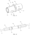
- FIG. 13 is a perspective of an insert of the micro connector assembly of FIG. 10 ;
- FIG. 14 is a perspective of ferrules and alignment sleeve of the micro connector assembly of FIG. 10 forming an optical connection
- FIG. 15 is an enlarged, fragmentary, top plan view of the micro connector assembly of FIG. 10 ;
- FIG. 16 is a cross-sectional view of the micro connector assembly of FIG. 10 taken through line 16 - 16 of FIG. 15 .
- a fiber optic connector assembly or micro connector assembly is generally indicated at reference numeral 10 .
- the fiber optic connector assembly 10 or more particularly a collection of its component parts, may be referred to as a “kit.”
- the fiber optic connector assembly 10 includes first and second ferrules 12 , 14 , and first and second micro connector ferrule housings 16 , 18 (a “first housing” and a “second housing”).
- the first ferrule 12 is connected to a first optical fiber F 1 .
- the second ferrule 14 is connected to a second optical fiber F 2 .
- the first and second ferrules 12 , 14 each define an internal passage (not shown) for receiving the first and second optical fibers F 1 , F 2 , respectively. In one embodiment, each ferrule 12 , 14 receives a single optical fiber.
- the fiber optic connector assembly 10 is used to form a fiber optic connection. When the fiber optic connector assembly 10 is assembled together, as shown in FIG. 1 , an optical connection (e.g., a fiber optic connection) is formed between the first and second ferrules 12 , 14 ( FIG. 3 ) that enables communication therebetween in an optical communications network (e.g., the first and second optical fibers F 1 , F 2 ). Other configurations of the fiber optic connector assembly 10 are within the scope of the present disclosure.
- the connector assembly could make electrical or other types of connections instead of or in addition to an optical connection.
- the fiber optic connector housings 16 , 18 are small and conform closely to the ferrules 12 , 14 so as to take up minimal space.
- the first and second housings 16 , 18 can be considered plug frames for their respective ferrules 12 , 14 .
- the first and second housings 16 , 18 each define a cavity sized and shaped to receive at least one of the first and second ferrules 12 , 14 .
- the first and second ferrules 12 , 14 are disposed in a closely spaced relation with the first and second housings 16 , 18 when in each cavity.
- the first and second housings 16 , 18 are generally cylindrical in shape.
- the polygonal shapes of the first housing 16 and a portion of the second housing 18 are considered generally cylindrical in this description.
- each cavity has a height and a width such that it can only receive only one ferrule 12 , 14 in heightwise and widthwise directions (e.g., cannot receive two ferrules in a side-by-side arrangement but may still be long enough to receive two ferrules in an end-to-end arrangement).
- the cavity of the first housing 16 is also sized in shaped to receive an insert portion 20 of the second housing 18 .
- the insert portion 20 defines a portion of the cavity of the second housing 18 and also receives at least a portion of the first ferrule 12 when the first and second housing are coupled together.
- the insert portion 20 can slide into and out of the first housing 16 (e.g., an open end thereof).
- the insert portion 20 (broadly, at least a portion of the second housing 18 ) is configured to be disposed within the first housing 16 when the first and second housings are coupled together.
- the first and second housings 16 , 18 each have fiber optic openings (e.g., in an end thereof) sized and shaped to correspond to the shape of the first and second optical fibers F 1 , F 2 , respectively, to permit the first and second optical fibers to pass through the respective first and second housings and into each respective cavity.
- the second housing 18 is configured to engage the first and second ferrules 12 , 14 to prevent the first and second ferrules from rotating relative to the second housing.
- the first and second ferrules 12 , 14 each include a flange 22 having a polygonal (e.g., hexagonal) cross-section (e.g., cross-sectional shape).
- the portion of the cavity defined by the insert portion 20 has a polygonal (e.g., hexagonal) cross-section that matches the polygonal cross-sections of the flanges 22 .
- first and second ferrules 12 , 14 are inhibited by the insert portion 20 when the flanges 22 of the first and second ferrules are disposed within the portion of the cavity of the second housing 18 defined by the insert portion.
- Other configurations of the first and second ferrules 12 , 14 are within the scope of the present disclosure.
- One example of alternative configurations of the first and second ferrules are generally indicated by reference numerals 12 ′ and 14 ′, respectively in FIG. 4 .
- the ferrules 12 ′, 14 ′ can be used with the fiber optic connector assembly 10 of FIG. 1 .
- first and second ferrules 12 ′, 14 ′ also include polygonal flanges 22 ′ but include mating end portions (e.g., tips) that are narrow than the mating end portions of the ferrules 12 , 14 of FIG. 3 .
- the overall shape of each flange 22 ′ differs from that of the flange 22
- the fiber optic connector assembly 10 may include an alignment sleeve 24 , 24 ′.
- the alignment sleeve 24 , 24 ′ is configured to receive the mating end portions of the first and second ferrules 12 , 12 ′, 14 , 14 ′.
- the alignment sleeve 24 , 24 ′ aligns the first and second ferrules 12 , 12 ′, 14 , 14 ′ with each other for the best optical transmission.
- the first and second housings 16 , 18 are configured to be releasably coupled (e.g., directly or indirectly coupled) together such that the first and second ferrules 12 , 12 ′, 14 , 14 ′ form an optical connection when the first and second housings are coupled together.
- the first and second housings 16 , 18 each have connection structure 26 , 28 (e.g., first connection structure, second connection structure) configured to releasably couple the first and second housings together.
- the connection structure 26 , 28 is formed integrally with a respective one of the first and second housings 16 , 18 . In the illustrated embodiment, the first and second housings 16 , 18 are configured to be directly coupled together.
- the first and second connection structures 26 , 28 are interengageable (e.g., directly engage each other) to releasably couple the first and second housings 16 , 18 together.
- the first connection structure 26 is part of the first housing 16 and the second connection structure 28 is part of the second housing 18 .
- the first connection structure 26 comprises a recess 30 formed into the first housing 16 .
- the second connection structure 28 comprises a protrusion 32 formed as one piece of material with the second housing 18 .
- the protrusion 32 is sized and shaped to be received in the recess.
- the recess 30 is defined by the first housing 16 . Positioning the protrusion 32 in the recess 30 couples the first and second housings 16 , 18 together.
- the first housing 16 defines a channel 34 extending from the recess 30 .
- the channel 34 is sized and shaped to permit the protrusion 32 to move within the channel (e.g., toward or away from the recess 30 ).
- the channel 34 is arcuate such that the second housing 18 rotates relative to the first housing 16 as the protrusion 32 is moved within the channel 34 .
- the first and second housings 16 , 18 are rotated relative to each other to couple and decouple from each other.
- the channel 34 has an open end opposite the recess 30 .
- the open end of the channel 34 is sized and shaped to permit the protrusion 32 to enter the channel and move toward the recess 30 to couple the first and second housings 16 , 18 together.
- the open end of the channel 34 is sized and shaped to permit the protrusion 32 to exit the channel and move away from the recess 30 to disconnect the first and second housing 16 , 18 from each other.
- first and second housings 16 , 18 are each an integral, one-piece component.
- the first and second housings 16 , 18 may each be a single piece of molded plastic.
- the first and second housings 16 , 18 may be formed from two or more pieces coupled or secured together.
- the fiber optic connector assembly 10 may include one or more biasing springs 36 (e.g., coil springs).
- the one or more biasing springs 36 are configured to bias at least one of the first or second ferrules 12 , 12 ′, 14 , 14 ′ toward the other respective ferrule when the first and second housings 16 , 18 are coupled together.
- the fiber optic connector assembly 10 includes one biasing spring 36 .
- the spring 36 helps maintain the optical connection between the first and second ferrules 12 , 12 ′, 14 , 14 ′.
- One end of the spring 36 engages the end of the first housing 16 and the other end of the spring engages the flange 22 , 22 ′ of the first ferrule 12 , 12 ′ and biases the first ferrule out of the first housing toward the second ferrule 14 , 14 ′.
- the spring 36 is received in the cavity of the first housing 16 .
- the spring 36 is also configured to bias the first and second housings 16 , 18 to remain in a locked position ( FIG. 1 ).
- the first and second housings 16 , 18 are releasably coupled together when the first and second housings are in the locked position.
- the protrusion 32 is disposed in the recess 30 .
- the first housing 16 includes a lip 38 bordering the recess 30 , which inhibits the protrusion from moving into the channel 34 unless the biasing force of the spring 36 is overcome (e.g., manually overcome). Accordingly, the spring 36 biases the first and second housings 16 , 18 away from each other.
- the first and second housings 16 , 18 are first pushed together (moving the protrusion 32 clear of the lip 38 ) and then rotated relative to one another to move the protrusion along and out of the channel 34 (through the open end).
- the protrusion 32 is moved into the channel 34 through the open end and then the first and second housings are rotated relative to one another to move the protrusion along the channel and into the recess 30 .
- first and second housings 16 , 18 are configured to rotated relative to each other to connect the first and second housings to each other and to be rotated relative to each other in an opposite direction(s) to disconnect the first and second housings from each other.
- the first optical fiber F 1 is threaded through the opening of the first housing 16 , the spring 36 is threaded onto the first optical fiber and then the first optical fiber is terminated in the first ferrule 12 , 12 ′.
- the second optical fiber F 2 is threaded through the opening of the second housing 18 and then connected to the second ferrule 14 , 14 ′.
- the first and second ferrules 12 , 12 ′, 14 , 14 ′ are then inserted into the alignment sleeve 24 , 24 ′.
- the first and second housing 16 , 18 are moved over the first and second ferrules 12 , 12 ′, 14 , 14 ′ and coupled together as described above, securing the optical connection.
- a fiber optic connector assembly or micro connector assembly is generally indicated at reference numeral 110 .
- the fiber optic connector assembly 110 or more particularly a collection of its component parts, may be referred to as a “kit.”
- the fiber optic connector assembly 110 includes first and second ferrules 112 , 114 , and first and second micro connector ferrule housings 116 , 118 (a “first housing” and a “second housing”).
- the first ferrule 112 is configured to be connected to a first optical fiber F 1 .
- the second ferrule 114 is configured to be connected to a second optical fiber F 2 .
- the first and second ferrules 112 , 114 each define an internal passage (not shown) for receiving the first and second optical fibers F 1 , F 2 , respectively.
- the fiber optic connector assembly 110 is used to form a fiber optic connection.
- an optical connection e.g., a fiber optic connection
- an optical communications network e.g., the first and second optical fibers F 1 , F 2 .
- Other configurations of the fiber optic connector assembly 110 are within the scope of the present disclosure.
- the connector assembly could make electrical or other types of connections instead of or in addition to an optical connection.
- the first and second housings 116 , 118 each define a cavity sized and shaped to receive at least one of the first and second ferrules 112 , 114 .
- the first and second ferrules 112 , 114 are disposed in a closely spaced relation with the first and second housings 116 , 118 when in each cavity.
- each cavity has a height and a width such that it can only receive only one ferrule 112 , 114 in heightwise and widthwise directions (e.g., can't receive two ferrules in a side-by-side arrangement but may still be long enough to receive two ferrules in an end-to-end arrangement).
- the first and second housings 116 , 118 are generally cylindrical in shape.
- the first and second housings 116 , 118 each have fiber optic openings sized and shaped to correspond to the shape of the first and second optical fibers F 1 , F 2 , respectively, to permit the first and second optical fibers to pass through the respective first and second housings and into each respective cavity.
- the fiber optic connector assembly 110 includes an insert 120 .
- the insert 120 is configured to be disposed in each cavity of the first and second housing 116 , 118 when the first and second housing are coupled together.
- the cavity of the first housing 116 is sized in shaped to receive a portion of the insert 120 and the cavity of the second housing 118 is sized and shaped to receive another portion of the insert.
- the insert 120 can slide into and out of the first and second housings 116 , 118 (e.g., open ends thereof).
- the insert 120 is configured to be disposed within the first and second housings 116 , 118 when the first and second housings are coupled together.
- the insert 120 is configured to engage the first and second ferrules 112 , 114 to prevent the first and second ferrules from rotating relative to each other.
- the insert 120 defines a ferrule cavity of sized and shaped to receive portions of the first and second ferrules 112 , 114 .
- the first and second ferrules 112 , 114 each include a flange 122 having a polygonal (e.g., hexagonal) cross-section (e.g., cross-sectional shape).
- the ferrule cavity defined by the insert 120 has a polygonal (e.g., hexagonal) cross-section that matches the polygonal cross-sections of the flanges 122 .
- the fiber optic connector assembly 110 may include an alignment sleeve 124 .
- the alignment sleeve 124 is configured to receive the mating end portions (e.g., tips) of the first and second ferrules 112 , 114 .
- the alignment sleeve 124 aligns the first and second ferrules 112 , 114 with each other.
- the alignment sleeve 124 is sized and shaped to be received in the ferrule cavity of the insert 120 . In other words, the alignment sleeve 124 is disposed in the insert 120 .
- the first and second housings 116 , 118 are configured to be releasably coupled (e.g., directly or indirectly coupled) together such that the first and second ferrules 112 , 114 , form an optical connection when the first and second housings are coupled together.
- the first and second housings 116 , 118 each have connection structure 126 , 128 (e.g., first connection structure, second connection structure) configured to releasably couple the first and second housings together.
- connection structure 126 , 128 e.g., first connection structure, second connection structure
- the first and second housings 116 , 118 are configured to be directly coupled together.
- the first and second connection structures 126 , 128 are interengageable (e.g., directly engage each other) to releasably couple the first and second housings 116 , 118 together.
- the first connection structure 126 is part of the first housing 116 and the second connection structure 128 is part of the second housing 118 .
- the first connection structure 126 comprises a first hook 130 and the second connection structure 128 comprises a second hook 132 .
- the first and second hooks 130 , 132 are configured to interlock ( FIG. 6 ) to releasably couple the first and second housings 116 , 118 together.
- the first hook 130 is integrally formed with the first housing 116 and the second hook 132 is integrally formed with the second housing 118 .
- align e.g., longitudinally align
- the first and second housings 116 , 118 is rotated relative to the other housing. In other words, the first and second housings 116 , 118 are rotated relative to each other to couple and decouple from each other.
- first and second housings 116 , 118 are identical to each other.
- the first and second housings 116 , 118 are each an integral, one-piece component.
- the first and second housings 116 , 118 may each be a single piece of molded plastic.
- the first and second housings 116 , 118 may be formed from two or more pieces coupled or secured together.
- the fiber optic connector assembly 110 may include one or more biasing springs 136 (e.g., coil springs).
- the one or more biasing springs 136 are configured to bias at least one of the first or second ferrules 112 , 114 out of their respective first or second housing 116 , 118 toward the other respective ferrule when the first and second housings are coupled together.
- the fiber optic connector assembly 110 includes two biasing spring 136 (e.g., a first spring and a second spring).
- the springs 136 help maintain the optical connection between the first and second ferrules 112 , 114 .
- the first spring 136 biases the first ferrule 112 toward the second ferrule 114 when the first and second housings 116 , 118 are coupled together.
- each spring 136 biases the second ferrule 114 toward the first ferrule 112 when the first and second housings 116 , 118 are coupled together.
- One end of each spring 136 engages the first or second housing 116 , 118 within its cavity and the other end of the spring engages the flange 122 of its corresponding first or second ferrule 112 , 114 .
- One spring 136 is received in the cavity of the first housing 116 and the other spring is received in the cavity of the second housing 118 .
- the spring 136 is also configured to bias the first and second housings 116 , 118 toward a locked position ( FIG. 6 ).
- the first and second housings 116 , 118 are releasably coupled together when the first and second housings are in the locked position.
- the first and second hooks 130 , 132 are interlocked with each other.
- the springs 136 bias the first and second hooks 130 , 132 toward each other. Due to the configuration of the first and second hooks 130 , 132 , the springs 136 bias the first and second housings 116 , 118 away from each other.
- the first and second housings are first pushed together (disengaging the first and second hooks 130 , 132 from each other) and then rotated relative to one another to move the first and second hooks out of alignment with each other.
- the first and second housings brought together and then rotated to relative to one another ( FIG. 9 ) to bring the first and second hooks 130 , 132 into alignment (e.g., longitudinal alignment) with each other ( FIG. 6 ).
- the first and second housings 116 , 118 are then moved apart, such as by the forces of the biasing springs 136 , to interlock the first and second hooks 130 , 132 .
- first and second housings 116 , 118 are configured to rotated (e.g., rotated in a first set of directions) relative to each other to connect the first and second housings to each other and to be rotated (e.g., rotated in a second set of directions, generally opposite the first set of directions) relative to each other to disconnect the first and second housings from each other.
- the first optical fiber F 1 is threaded through the opening of the first housing 116 , the first spring 136 is threaded onto the first optical fiber and then the first optical fiber is terminated in the first ferrule 112 .
- the second optical fiber F 2 is threaded through the opening of the second housing 118 , the second spring 136 is threaded onto the second optical fiber and then the second optical fiber is terminated in the second ferrule 114 .
- One of the first and second ferrules 112 , 114 can then be threaded into the insert 120 .
- the first and second ferrules 112 , 114 are then inserted into the alignment sleeve 124 and then moved back into the insert 120 .
- first and second housings 116 , 118 are moved over the insert 120 and coupled together as described above, securing the optical connection.
- the insert 120 facilitates the longitudinal alignment of the first and second housings 116 , 118 and the first and second housings can each slide over and rotate about the insert.
- a fiber optic connector assembly or micro connector assembly is generally indicated at reference numeral 210 .
- the fiber optic connector assembly 210 or more particularly a collection of its component parts, may be referred to as a “kit.”
- the fiber optic connector assembly 210 includes first and second ferrules 212 , 214 , and first and second micro connector ferrule housings 216 , 218 (a “first housing” and a “second housing”).
- the first ferrule 212 is configured to be connected to a first optical fiber F 1 .
- the second ferrule 214 is configured to be connected to a second optical fiber F 2 .
- the first and second ferrules 212 , 214 each define an internal passage 215 ( FIG. 16 ) for receiving the first and second optical fibers F 1 , F 2 , respectively.
- the fiber optic connector assembly 210 is used to form a fiber optic connection. When the fiber optic connector assembly 210 is assembled together, as shown in FIG. 10 , an optical connection is formed between the first and second ferrules 212 , 214 that enables communication therebetween in an optical communications network (e.g., the first and second optical fibers F 1 , F 2 ).
- an optical communications network e.g., the first and second optical fibers F 1 , F 2
- Other configurations of the fiber optic connector assembly 210 are within the scope of the present disclosure.
- the connector assembly could make electrical or other types of connections instead of or in addition to an optical connection.
- the first and second housings 216 , 218 each define a cavity sized and shaped to receive at least one of the first and second ferrules 212 , 214 .
- the first and second ferrules 212 , 214 are disposed in a closely spaced relation with the first and second housings 216 , 218 when in each cavity.
- each cavity has a height and a width such that it can only receive only one ferrule 212 , 214 in heightwise and widthwise directions (e.g., can't receive two ferrules in a side-by-side arrangement but may still be long enough to receive two ferrules in an end-to-end arrangement).
- the first and second housings 216 , 218 are generally cylindrical in shape.
- the first and second housings 216 , 218 each have fiber optic openings (e.g., in an end thereof) sized and shaped to correspond to the shape of the first and second optical fibers F 1 , F 2 , respectively, to permit the first and second optical fibers to pass through the respective first and second housings and into each respective cavity.
- the fiber optic connector assembly 210 includes an insert 220 .
- the insert 220 is configured to be disposed in each cavity of the first and second housings 216 , 218 when the first and second housings are coupled together.
- the cavity of the first housing 216 is sized in shaped to receive a portion of the insert 220 and the cavity of the second housing 218 is sized and shaped to receive another portion of the insert.
- the insert 120 can slide into and out of the first and second housings 216 , 218 (e.g., open ends thereof).
- the insert 220 is configured to be disposed within the first and second housings 216 , 218 when the first and second housings are coupled together.
- the insert 220 is configured to engage the first and second ferrules 212 , 214 to prevent the first and second ferrules from rotating relative to each other.
- the insert 220 defines a ferrule cavity 221 of sized and shaped to receive portions of the first and second ferrules 212 , 214 .
- the first and second ferrules 212 , 214 each include a flange 222 having a polygonal (e.g., hexagonal) cross-section (e.g., cross-sectional shape).
- the ferrule cavity 221 defined by the insert 220 has a polygonal (e.g., hexagonal) cross-section that matches the polygonal cross-sections of the flanges 222 .
- the fiber optic connector assembly 210 may include an alignment sleeve 224 .
- the alignment sleeve 224 is configured to receive the mating end portions (e.g., tips) of the first and second ferrules 212 , 214 .
- the alignment sleeve 224 aligns the first and second ferrules 212 , 214 with each other.
- the alignment sleeve 224 is sized and shaped to be received in the ferrule cavity 221 of the insert 220 . In other words, the alignment sleeve 224 is disposed in the insert 220 .
- the first and second housings 216 , 218 are configured to be releasably coupled (e.g., directly or indirectly coupled) together such that the first and second ferrules 212 , 214 , form an optical connection when the first and second housings are coupled together.
- the first and second housings 216 , 218 each have at least one connection structure 226 , 228 (e.g., at least one first connection structure, at least one second connection structure) configured to releasably couple the first and second housings together.
- the first and second housings 216 , 218 are configured to be indirectly coupled together.
- the first and second housings 216 , 218 are configured to be coupled together via the insert 220 .
- the first and second connection structures 226 , 228 engage the insert 220 to releasably couple the first and second housings 216 , 218 together.
- the at least one first connection structure 226 is formed as part of the first housing 216 and the at least one second connection structure 228 is formed as part of the second housing 218 .
- the first housing 216 includes two first connection structures 226 and the second housing 218 includes two second connection structures 228 .
- Each first connection structure 226 comprises a first recess or opening 231 bounded in part by a first shoulder or face 230 and each second connection structure 228 comprises a second recess or opening 233 bounded in part by a second shoulder or face 232 .
- the insert 220 includes at least one first detent 238 and at least one second detent 240 .
- the insert 220 includes two first detents 238 and two second detents 240 .
- Each first detent 238 corresponds to one of the first connections structures 226 and each second detent 240 corresponds to one of the second connection structure 228 .
- Each first detent 238 is configured to engage one of the first connection structures 226 and each second detent 240 is configured to engage one of the second connection structures 228 to releasably coupled the first housing 216 , the second housing 218 and the insert 220 together.
- each first detent 238 is configured to be received in the first opening 231 of the corresponding first connection structure 226 and engage the first face 230 (broadly, the first housing 216 ).
- each second detent 240 is configured to be received in the second opening 233 of the corresponding second connection structure 228 and engage the second face 232 (broadly, the second housing 218 ).
- Each detent 238 , 240 includes a first or longitudinal deflection ramp 242 and a second or lateral deflection ramp 244 .
- the first and second deflection ramps 242 , 244 extend generally perpendicular relative to each other.
- the first deflection ramp 242 is configured to facilitate the connection of the first or second housing 216 , 218 to the insert 220 .
- the first deflection ramp 242 of each detent 238 , 240 is arranged to deflect the corresponding first or second housing 216 , 218 (e.g., a portion thereof) as said first or second housing is connected to the insert 220 .
- the first and second housings 216 , 218 are configured to move along a longitudinal axis of the insert 220 to connect to the insert.
- first and second housings 216 , 218 are connected to the insert 220 by longitudinally sliding each housing over the insert. As the first and second housings 216 , 218 slide along the insert 220 , the housings engage the first deflection ramps 242 , which resiliently deflect the housings to permit the housings to move along and over the detents 238 , 240 . Once the first or second opening 231 , 233 of each housing 216 , 218 becomes aligned with the corresponding detent 238 , 240 , each housing returns or snaps-back to its undeformed or undeflected state thereby securing each housing to the insert 220 (e.g., a snap-fit connection is formed).
- each detent 238 , 240 faces and engages the corresponding first or second face 230 , 232 to inhibit disconnection of each housing 216 , 218 with the insert 220 .
- Each first and second housing 216 , 218 may include one or more relief slots 246 ( FIG. 16 ) to facilitate the portion of each of the first and second housings being resiliently deflected by the ramps 242 of the detents 238 , 240 .
- the insert 220 includes a circumferential flange 248 extending around the circumference of the insert. The circumferential flange 248 acts as a stop to prevent over insertion of the first and second housings 216 , 218 on the insert 220 .
- the second deflection ramp 244 is configured to facilitate the disconnection of the first or second housing 216 , 218 from the insert 220 .
- the second deflection ramp 244 of each detent 238 , 240 is arranged to deflect the corresponding first or second housing 216 , 218 (e.g., the portion thereof) as said first or second housing is disconnected from the insert 220 .
- the first and second housings 216 , 218 are configured to rotate ( FIG. 10 ) about the longitudinal axis of the insert 220 to disconnect from the insert. Specifically, the first and second housings 216 , 218 are disconnected to the insert 220 by rotating each housing over the insert ( FIG. 16 ).
- the housings engage the second deflection ramps 244 , which resiliently deflects the housings to permit the housings to move along and over the detents 238 , 240 .
- the first and second housings 216 , 218 are rotated relative to the insert 220 (and each other) to and decouple from each other.
- the first and second housings 216 , 218 are configured to rotated relative to each other (and the insert 220 ) to disconnect the first and second housings from each other.
- first and second housings 216 , 218 are identical to each other.
- the first and second housings 216 , 218 are each an integral, one-piece component.
- the first and second housings 216 , 218 may each be a single piece of molded plastic.
- the first and second housings 216 , 218 may be formed from two or more pieces coupled or secured together.
- the fiber optic connector assembly 210 may include one or more biasing springs 236 (e.g., coil springs).
- the one or more biasing springs 236 are configured to bias at least one of the first or second ferrules 212 , 214 toward the other respective ferrule when the first and second housings 216 , 218 are coupled together.
- the fiber optic connector assembly 210 includes two biasing spring 236 (e.g., a first spring and a second spring). The springs 236 help maintain the optical connection between the first and second ferrules 212 , 214 .
- the first spring 236 biases the first ferrule 212 out of the first housing 216 toward the second ferrule 214 when the first and second housings 216 , 218 are coupled together.
- the second spring 236 biases the second ferrule 214 out of the second housing 218 toward the first ferrule 212 when the first and second housings 216 , 218 are coupled together.
- One end of each spring 236 engages the corresponding first or second housing 216 , 218 within the cavity, and the other end of the spring engages the flange 222 of its corresponding first or second ferrule 212 , 214 .
- One spring 236 is received in the cavity of the first housing 216 and the other spring is received in the cavity of the second housing 218 .
- the spring 236 is also configured to bias the first and second housings 216 , 218 toward a locked position ( FIG. 10 ).
- the first and second housings 216 , 218 are releasably coupled together when the first and second housings are in the locked position.
- the springs 236 bias the first and second housings 216 , 218 away from each other. Accordingly, in the locked position, the first detents 238 engage and are biased against the first faces 230 and the second detents 240 engage and are biased against the second faces 232 .
- the first optical fiber F 1 is threaded through the opening of the first housing 216 , the first spring 236 is threaded onto the first optical fiber and then the first optical fiber is terminated in the first ferrule 212 .
- the second optical fiber F 2 is threaded through the opening of the second housing 218 , the second spring 236 is threaded onto the second optical fiber and then the second optical fiber is terminated in the second ferrule 214 .
- One of the first and second ferrules 212 , 214 can then be threaded into the insert 220 .
- the first and second ferrules 212 , 214 are then inserted into the alignment sleeve 224 and then moved back into the insert 220 .
- first and second housings 216 , 218 are moved longitudinally over the insert 220 and coupled together as described above, securing the optical connection.
- the insert 220 facilitates the longitudinal alignment of the first and second housings 216 , 218 and the first and second housings can each slide over and rotate about the insert.
- the micro connection assembly 10 , 110 , 210 may come as a kit that includes the first and second ferrules 12 , 12 ′, 14 , 14 ′, 112 , 114 , 212 , 214 , the first and second housings 16 , 18 , 116 , 118 , 216 , 216 , the insert 120 , 220 , the alignment sleeve 24 , 24 ′, 124 , 224 and/or the spring(s) 36 , 136 , 216 .
- kit configurations are within the scope of the present disclosure.
Abstract
Description
Claims (10)
Priority Applications (3)
| Application Number | Priority Date | Filing Date | Title |
|---|---|---|---|
| US17/196,683 US11592624B2 (en) | 2020-03-11 | 2021-03-09 | Fiber optic micro connector |
| US17/198,520 US20210286136A1 (en) | 2020-03-11 | 2021-03-11 | Fiber optic micro connector |
| CN202110266238.9A CN113391402A (en) | 2020-03-11 | 2021-03-11 | Optical fiber micro connector |
Applications Claiming Priority (2)
| Application Number | Priority Date | Filing Date | Title |
|---|---|---|---|
| US202062988361P | 2020-03-11 | 2020-03-11 | |
| US17/196,683 US11592624B2 (en) | 2020-03-11 | 2021-03-09 | Fiber optic micro connector |
Related Child Applications (1)
| Application Number | Title | Priority Date | Filing Date |
|---|---|---|---|
| US17/198,520 Continuation US20210286136A1 (en) | 2020-03-11 | 2021-03-11 | Fiber optic micro connector |
Publications (2)
| Publication Number | Publication Date |
|---|---|
| US20210286135A1 US20210286135A1 (en) | 2021-09-16 |
| US11592624B2 true US11592624B2 (en) | 2023-02-28 |
Family
ID=77663687
Family Applications (2)
| Application Number | Title | Priority Date | Filing Date |
|---|---|---|---|
| US17/196,683 Active US11592624B2 (en) | 2020-03-11 | 2021-03-09 | Fiber optic micro connector |
| US17/198,520 Abandoned US20210286136A1 (en) | 2020-03-11 | 2021-03-11 | Fiber optic micro connector |
Family Applications After (1)
| Application Number | Title | Priority Date | Filing Date |
|---|---|---|---|
| US17/198,520 Abandoned US20210286136A1 (en) | 2020-03-11 | 2021-03-11 | Fiber optic micro connector |
Country Status (1)
| Country | Link |
|---|---|
| US (2) | US11592624B2 (en) |
Families Citing this family (1)
| Publication number | Priority date | Publication date | Assignee | Title |
|---|---|---|---|---|
| GB2622104A (en) * | 2022-09-05 | 2024-03-06 | Ridgemount Tech Limited | A fibre optic connector body, a kit of parts, a fibre optic connector and use of the same |
Citations (15)
| Publication number | Priority date | Publication date | Assignee | Title |
|---|---|---|---|---|
| US5212752A (en) | 1992-05-27 | 1993-05-18 | At&T Bell Laboratories | Optical fiber ferrule connector having enhanced provisions for tuning |
| US5216733A (en) | 1991-03-11 | 1993-06-01 | Nippon Telegraph And Telephone Corporation | Polarization maintaining optical fiber connector including positioning flange and method utilizing same |
| US5598495A (en) | 1992-11-13 | 1997-01-28 | International Business Machines Corporation | Fiber optic connector housing, fiber optic receptacle, accessories employing fiber optic connector housings and corresponding optical assemblies |
| US6217231B1 (en) | 1997-04-23 | 2001-04-17 | Fujitsu Limited | Optical fiber assembly, optical module including an optical fiber assembly, and a manufacturing process thereof |
| JP2001147347A (en) * | 1999-11-22 | 2001-05-29 | Japan Aviation Electronics Industry Ltd | Optical connector |
| WO2002027374A1 (en) * | 2000-09-29 | 2002-04-04 | Telefonaktiebolaget Lm Ericsson (Publ) | A contact device |
| JP3369057B2 (en) | 1996-09-18 | 2003-01-20 | 日本電信電話株式会社 | Optical connector for polarization maintaining fiber |
| JP2003329880A (en) | 2002-05-17 | 2003-11-19 | Adamant Kogyo Co Ltd | Ferrule |
| US20060193562A1 (en) | 2005-02-25 | 2006-08-31 | Thomas Theuerkorn | Fiber optic receptacle and plug assembly including alignment sleeve insert |
| US20090220227A1 (en) | 2008-03-03 | 2009-09-03 | Avago Technologies Fiber Ip (Singapore) Pte. Ltd. | Small form factor pluggable (sfp) optical transceiver module and method |
| US20100310213A1 (en) | 2005-03-10 | 2010-12-09 | Christopher Paul Lewallen | Multi-Fiber Fiber Optic Receptacle and Plug Assembly |
| US20170242199A1 (en) | 2015-08-27 | 2017-08-24 | Senko Advanced Components, Inc. | Micro Hybrid LC Duplex Adapter |
| US20170269315A1 (en) | 2016-03-17 | 2017-09-21 | Applied Optoelectronics, Inc. | Coaxial transmitter optical subassembly (tosa) with an optical fiber coupling receptacle |
| US20170285274A1 (en) * | 2016-04-04 | 2017-10-05 | Hirose Electric Co., Ltd. | Optical connector and method for connecting optical fiber cables |
| US20200326495A1 (en) | 2019-04-11 | 2020-10-15 | Prime World International Holdings Ltd. | Optical transceiver |
-
2021
- 2021-03-09 US US17/196,683 patent/US11592624B2/en active Active
- 2021-03-11 US US17/198,520 patent/US20210286136A1/en not_active Abandoned
Patent Citations (15)
| Publication number | Priority date | Publication date | Assignee | Title |
|---|---|---|---|---|
| US5216733A (en) | 1991-03-11 | 1993-06-01 | Nippon Telegraph And Telephone Corporation | Polarization maintaining optical fiber connector including positioning flange and method utilizing same |
| US5212752A (en) | 1992-05-27 | 1993-05-18 | At&T Bell Laboratories | Optical fiber ferrule connector having enhanced provisions for tuning |
| US5598495A (en) | 1992-11-13 | 1997-01-28 | International Business Machines Corporation | Fiber optic connector housing, fiber optic receptacle, accessories employing fiber optic connector housings and corresponding optical assemblies |
| JP3369057B2 (en) | 1996-09-18 | 2003-01-20 | 日本電信電話株式会社 | Optical connector for polarization maintaining fiber |
| US6217231B1 (en) | 1997-04-23 | 2001-04-17 | Fujitsu Limited | Optical fiber assembly, optical module including an optical fiber assembly, and a manufacturing process thereof |
| JP2001147347A (en) * | 1999-11-22 | 2001-05-29 | Japan Aviation Electronics Industry Ltd | Optical connector |
| WO2002027374A1 (en) * | 2000-09-29 | 2002-04-04 | Telefonaktiebolaget Lm Ericsson (Publ) | A contact device |
| JP2003329880A (en) | 2002-05-17 | 2003-11-19 | Adamant Kogyo Co Ltd | Ferrule |
| US20060193562A1 (en) | 2005-02-25 | 2006-08-31 | Thomas Theuerkorn | Fiber optic receptacle and plug assembly including alignment sleeve insert |
| US20100310213A1 (en) | 2005-03-10 | 2010-12-09 | Christopher Paul Lewallen | Multi-Fiber Fiber Optic Receptacle and Plug Assembly |
| US20090220227A1 (en) | 2008-03-03 | 2009-09-03 | Avago Technologies Fiber Ip (Singapore) Pte. Ltd. | Small form factor pluggable (sfp) optical transceiver module and method |
| US20170242199A1 (en) | 2015-08-27 | 2017-08-24 | Senko Advanced Components, Inc. | Micro Hybrid LC Duplex Adapter |
| US20170269315A1 (en) | 2016-03-17 | 2017-09-21 | Applied Optoelectronics, Inc. | Coaxial transmitter optical subassembly (tosa) with an optical fiber coupling receptacle |
| US20170285274A1 (en) * | 2016-04-04 | 2017-10-05 | Hirose Electric Co., Ltd. | Optical connector and method for connecting optical fiber cables |
| US20200326495A1 (en) | 2019-04-11 | 2020-10-15 | Prime World International Holdings Ltd. | Optical transceiver |
Non-Patent Citations (1)
| Title |
|---|
| International Search Report and Written Opinion, Application No. PCT/US20/058358, dated Mar. 4, 2021,11 pages. |
Also Published As
| Publication number | Publication date |
|---|---|
| US20210286136A1 (en) | 2021-09-16 |
| US20210286135A1 (en) | 2021-09-16 |
Similar Documents
| Publication | Publication Date | Title |
|---|---|---|
| US11822142B2 (en) | Low cost hardened fiber optic connection system | |
| US6634796B2 (en) | Polarity reversal for fiber optic connections | |
| EP0468671B1 (en) | Fiber optic interconnect for wall outlet | |
| US7677814B2 (en) | Mechanical interface converter for making non-ruggedized fiber optic connectors compatible with a ruggedized fiber optic adapter | |
| US10598870B2 (en) | Fiber optic connector with dual multi-fiber ferrules, and cable assemblies and systems including the same | |
| US11921329B2 (en) | Fiber optic connectors and fiber optic connection systems | |
| US11747572B2 (en) | Reversible polarity fiber optic connector | |
| US10317627B2 (en) | Optical adaptor for mounting to a receptacle to optically couple connectorized optical cables | |
| US20230244041A1 (en) | Telecommunications connector with latch release mechanism | |
| US11592624B2 (en) | Fiber optic micro connector | |
| US11353664B1 (en) | Fiber optic connector | |
| US11733465B2 (en) | Multiport assembly and associated components | |
| CN113391402A (en) | Optical fiber micro connector | |
| US11609387B2 (en) | Fiber optic micro connector | |
| US20240045153A1 (en) | Optical cable connector end-piece, optical connection joint, optical adapter and optical cable connector assembly | |
| US20230142093A1 (en) | Fiber optic adapters for use with fiber optic connectors and methods for coupling fiber optic connectors | |
| WO2022086570A1 (en) | Fiber optic micro connector | |
| CN112711107A (en) | Optical fiber micro-connector | |
| CN114488417A (en) | Optical fiber connector and optical fiber connector | |
| WO2022081547A1 (en) | Multi-fiber connector system |
Legal Events
| Date | Code | Title | Description |
|---|---|---|---|
| FEPP | Fee payment procedure |
Free format text: ENTITY STATUS SET TO UNDISCOUNTED (ORIGINAL EVENT CODE: BIG.); ENTITY STATUS OF PATENT OWNER: LARGE ENTITY |
|
| FEPP | Fee payment procedure |
Free format text: ENTITY STATUS SET TO SMALL (ORIGINAL EVENT CODE: SMAL); ENTITY STATUS OF PATENT OWNER: LARGE ENTITY |
|
| STPP | Information on status: patent application and granting procedure in general |
Free format text: DOCKETED NEW CASE - READY FOR EXAMINATION |
|
| STPP | Information on status: patent application and granting procedure in general |
Free format text: NON FINAL ACTION MAILED |
|
| STPP | Information on status: patent application and granting procedure in general |
Free format text: RESPONSE TO NON-FINAL OFFICE ACTION ENTERED AND FORWARDED TO EXAMINER |
|
| STPP | Information on status: patent application and granting procedure in general |
Free format text: NOTICE OF ALLOWANCE MAILED -- APPLICATION RECEIVED IN OFFICE OF PUBLICATIONS |
|
| AS | Assignment |
Owner name: SENKO ADVANCED COMPONENTS, INC., MASSACHUSETTS Free format text: ASSIGNMENT OF ASSIGNORS INTEREST;ASSIGNOR:KONNO, RYO;REEL/FRAME:062449/0785 Effective date: 20200923 Owner name: SENKO ADVANCED COMPONENTS, INC., MASSACHUSETTS Free format text: ASSIGNMENT OF ASSIGNORS INTEREST;ASSIGNORS:IIZUMI, KENJI;TAKANO, KAZUYOSHI;REEL/FRAME:062449/0632 Effective date: 20230123 |
|
| FEPP | Fee payment procedure |
Free format text: ENTITY STATUS SET TO UNDISCOUNTED (ORIGINAL EVENT CODE: BIG.); ENTITY STATUS OF PATENT OWNER: LARGE ENTITY |
|
| STCF | Information on status: patent grant |
Free format text: PATENTED CASE |