US11591872B2 - Setting tool for downhole applications - Google Patents
Setting tool for downhole applications Download PDFInfo
- Publication number
- US11591872B2 US11591872B2 US17/157,750 US202117157750A US11591872B2 US 11591872 B2 US11591872 B2 US 11591872B2 US 202117157750 A US202117157750 A US 202117157750A US 11591872 B2 US11591872 B2 US 11591872B2
- Authority
- US
- United States
- Prior art keywords
- piston
- tool
- cavity
- setting
- stroke
- Prior art date
- Legal status (The legal status is an assumption and is not a legal conclusion. Google has not performed a legal analysis and makes no representation as to the accuracy of the status listed.)
- Active, expires
Links
Images


Classifications
-
- E—FIXED CONSTRUCTIONS
- E21—EARTH DRILLING; MINING
- E21B—EARTH DRILLING, e.g. DEEP DRILLING; OBTAINING OIL, GAS, WATER, SOLUBLE OR MELTABLE MATERIALS OR A SLURRY OF MINERALS FROM WELLS
- E21B23/00—Apparatus for displacing, setting, locking, releasing, or removing tools, packers or the like in the boreholes or wells
- E21B23/06—Apparatus for displacing, setting, locking, releasing, or removing tools, packers or the like in the boreholes or wells for setting packers
- E21B23/065—Apparatus for displacing, setting, locking, releasing, or removing tools, packers or the like in the boreholes or wells for setting packers setting tool actuated by explosion or gas generating means
-
- E—FIXED CONSTRUCTIONS
- E21—EARTH DRILLING; MINING
- E21B—EARTH DRILLING, e.g. DEEP DRILLING; OBTAINING OIL, GAS, WATER, SOLUBLE OR MELTABLE MATERIALS OR A SLURRY OF MINERALS FROM WELLS
- E21B23/00—Apparatus for displacing, setting, locking, releasing, or removing tools, packers or the like in the boreholes or wells
- E21B23/06—Apparatus for displacing, setting, locking, releasing, or removing tools, packers or the like in the boreholes or wells for setting packers
-
- C—CHEMISTRY; METALLURGY
- C06—EXPLOSIVES; MATCHES
- C06B—EXPLOSIVES OR THERMIC COMPOSITIONS; MANUFACTURE THEREOF; USE OF SINGLE SUBSTANCES AS EXPLOSIVES
- C06B33/00—Compositions containing particulate metal, alloy, boron, silicon, selenium or tellurium with at least one oxygen supplying material which is either a metal oxide or a salt, organic or inorganic, capable of yielding a metal oxide
- C06B33/02—Compositions containing particulate metal, alloy, boron, silicon, selenium or tellurium with at least one oxygen supplying material which is either a metal oxide or a salt, organic or inorganic, capable of yielding a metal oxide with an organic non-explosive or an organic non-thermic component
-
- C—CHEMISTRY; METALLURGY
- C06—EXPLOSIVES; MATCHES
- C06D—MEANS FOR GENERATING SMOKE OR MIST; GAS-ATTACK COMPOSITIONS; GENERATION OF GAS FOR BLASTING OR PROPULSION (CHEMICAL PART)
- C06D5/00—Generation of pressure gas, e.g. for blasting cartridges, starting cartridges, rockets
- C06D5/06—Generation of pressure gas, e.g. for blasting cartridges, starting cartridges, rockets by reaction of two or more solids
Definitions
- the present invention relates, generally, to the field of downhole tools and methods of setting such downhole tools within a well bore. More particularly, the embodiments of the present invention relate to a non-explosive, gas-generating setting tool usable for downhole applications.
- Such tools can include plugs, packers, hangers, casing patches, and the like (collectively referred to herein as downhole tools).
- a “setting tool” refers to a tool that is used to deploy a “downhole tool” within a wellbore).
- the setting tool carries the downhole tool to the desired location within the wellbore and also actuates mechanisms that anchor the downhole tool within the wellbore.
- a setting tool is typically connected to the downhole tool and the pair of tools (i.e., setting tool and downhole tool) is run down the wellbore using a slickline, coiled tubing, or other conveying method. Once the pair of tools reaches the desired depth within the wellbore, the setting tool deploys the downhole tool.
- a variety of types of setting tools that operate according to a variety of designs are known in the art.
- Setting tools differ from one another with regard to the method by which they produce the output needed to actuate the downhole tools and, consequently, the amount of force they are capable of producing.
- Examples of force generating methods include hydraulic, electromechanical, mechanical, and pyrotechnic (explosive) methods.
- Each type of setting tool has associated advantages and disadvantages.
- a disadvantage of hydraulic setting tools is that they generally require that fluid be pumped to the tool from the surface to pressurize and actuate the tool's setting mechanisms.
- a pyrotechnic-based setting tool may be actuated using a timer or condition sensor that is contained within the setting tool itself, allowing the setting tool to operate without communicating with the surface to activate the setting tool.
- condition sensors include sensors that monitor acceleration, hydrostatic pressure, temperature, or a combination of these or other conditions.
- Pyrotechnic-based setting tools have several problems.
- One problem is that the highly explosive materials they require to operate are generally dangerous and are typically subject to import/export and travel restrictions.
- the setting tool can remain pressurized following detonation and must be depressurized by bleeding off pressure from the tool, by rupturing a bleed off mechanism at the surface—an operation that can be hazardous.
- pyrotechnic-type setting tools produce pressure in an explosive manner.
- the impulse generated by the rapid expansion of gases upon detonation in such a setting tool may not generate the optimum pressure for deploying downhole tools. Basically, the explosion may generate too much overpressure, over too short of a time, to properly set the downhole tool. Consequently, the force of the explosion must be throttled or dampened—a function typically performed using an internal hydraulic transducing mechanism. But such tools are limited in their application because they can only produce adequate force over short distances.
- the present invention relates to a non-explosive, gas-generating setting tool usable for setting downhole tools, such as a include a packer, a bridge plug, a fracturing plug, or other similar downhole tools, within a well bore.
- a setting tool may include a tool body coupled to a well tool that can be configured to be deployed downhole within a well, and a chamber within the tool body that can be configured to contain a non-explosive fuel, which can be configured to be initiated to generate gas and plasma.
- the setting tool can also include a cavity within the tool body, a bleed sub located within the tool body between the chamber and the cavity, wherein the bleed sub is configured to bleed pressure from the chamber to the cavity after the non-explosive fuel has been initiated, and a piston disposed within the cavity and oriented to stroke in a first direction in response to a pressure increase in the cavity after the non-explosive fuel has been initiated.
- the piston can divide the cavity into an upper volume and a lower volume, and the upper volume can receive the pressure increase from the bleed sub.
- the setting tool can include a shaft mechanically connected to the piston within the lower volume of the cavity.
- the shaft can include a dampening conduit that can be configured to drain a fluid from the lower volume after the non-explosive fuel has been initiated.
- the dampening conduit is configured to drain the fluid to a location that is external to the tool body.
- the fluid that drains from the lower volume may have a higher viscosity, e.g., the fluid can be oil, an oil derivative, or a synthetic lubricant, that flows more slowly than a less viscose fluid through the dampening conduit.
- a fluid having a higher viscosity, such as oil, an oil derivative, or a synthetic lubricant can enhance the control of the stroke of the piston, which in turn can produce a more precise actuating force on the downhole tool.
- the fluid may be at least one of non-flammable, not-toxic, and non-corrosive.
- the higher viscosity fluid may reduce the rate of travel of the piston during the piston stroke to be within a range of 0.25 inches per second to 10 inches per second.
- the dampening conduit comprises an inlet hole and an outlet hole that are adjustable or customizable to change the flow of the fluid through the dampening conduit.
- the dampening conduit can include an inlet hole in the shaft that is between 1 cm (0.39 inches) and 3 cm (1.18 inches) from the piston.
- the setting tool may further include a snubber within the tool body configured to decelerate the piston and the shaft.
- the dampening conduit can be shaped to slow the flow of the fluid, and to slow the stroke of the piston in the first direction.
- the tool body can include a first inside diameter, with one or more o-rings disposed upon the piston to form a gas-tight seal between the piston and the first inside diameter.
- the setting tool can include a second inside diameter longitudinally disposed with respect to the first inside diameter, the second inside diameter may be greater than the first inside diameter. Also, the piston may stroke in the first direction from the first inside diameter to the second inside diameter, where the one or more o-rings do not form a gas-tight seal between the piston and the second inside diameter.
- the disclosed embodiments include a method of setting a setting tool.
- the method can include the steps of activating a power source to generate a source of expanding gases within a first cavity, expanding the expanding gases through a bleed sub to a second cavity, stroking a piston through the second cavity with the expanding gases, and decelerating the piston before the piston completes a stroke length.
- the method can include bleeding the expanding gases to an external area of the setting tool. Bleeding the expanding gases may include releasing a gas-tight seal between the piston and an inner diameter of the setting tool.
- the method can include setting a downhole tool such as a packer, a bridge plug, a fracturing plug, or combinations thereof.
- a downhole tool such as a packer, a bridge plug, a fracturing plug, or combinations thereof.
- setting the setting tool can include filtering the expanding gases through a filtering plug.
- the filtering plug can be configured to filter solid particulates that are produced by the power source.
- the method may also include stroking the piston to push a crosslink key with a shaft.
- decelerating the piston can include deforming a snubber, or forcing fluid through a dampening conduit within a shaft of the setting tool.
- the shaft can be attached to, and stroke with, the piston.
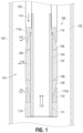
- FIG. 1 illustrates a downhole tool according to an embodiment.
- FIG. 2 illustrates an embodiment of an explosive-based setting tool.
- FIGS. 3 A and 3 B illustrate an embodiment of a non-explosive gas-generating setting tool in the pre-function and post-function configuration, respectively.
- FIGS. 3 C to 3 F illustrate further views of the non-explosive gas-generating setting tool shown in FIGS. 3 A and 3 B , wherein FIG. 3 D is an enlarged view of a portion of FIG. 3 C , and FIG. 3 F is an enlarged view of a portion of FIG. 3 E .
- FIG. 4 illustrates an embodiment of a self-bleed mechanism for a non-explosive gas-generating setting tool.
- FIG. 5 illustrates an embodiment of a manual bleed sub for a non-explosive gas-generating setting tool.
- FIG. 6 is an exploded view of an embodiment of a non-explosive gas-generating setting tool.
- FIG. 7 illustrates a pressure curve for an explosive-type setting tool and a non-explosive gas-generating setting tool.
- FIG. 8 illustrates embodiments of a non-explosive gas-generating fuel.
- FIGS. 9 A to 9 F are schematic illustrations of modular non-explosive gas-generating setting tools.
- FIG. 10 illustrates a non-explosive gas-generating setting tool containing lateral support members to prevent the tool's shaft from buckling.
- FIG. 1 illustrates a mechanism for anchoring a downhole tool 100 in a wellbore 101 .
- Wellbore 101 includes a tubular member 102 having an inner diameter (ID) 103 .
- Tubular member 102 may be production tubing, casing, production liner or any other structure defining the walls of a wellbore.
- Wellbore 101 is illustrated as being substantially larger in diameter than downhole tool 100 , but this is for illustration purposes only. Generally, the downhole tool 101 would have a diameter only slightly smaller than ID 103 of tubular member 102 .
- Downhole tool 100 includes a mandrel 104 having cone-shaped protrusions 105 and 106 and a sealing section 107 .
- Cone-shaped protrusions 105 and 106 can slide over the mandrel 104 and make contact with sealing section 107 via surfaces 108 and 109 , respectively.
- Sealing section 107 is typically made of a deformable or otherwise malleable material, such as plastic, metal, an elastomer or the like.
- Downhole tool 100 further includes a base section 110 attached to the mandrel 104 via a threaded section 111 .
- Base section 110 can apply pressure to cone-shaped protrusion 105 via slips 112 when the mandrel 104 is moved in an upward direction 113 .
- Cone-shaped protrusion 105 consequently slides up and over the mandrel 104 , applying pressure to the sealing section 107 .
- Downward pressure 114 to slips 115 (usually exerted by a sleeve 120 ) likewise transfers pressure to the sealing member 107 as the cone-shaped protrusion 106 slides downward.
- Sealing member 107 deforms and expands due to lateral pressure 116 (with force line indicated), as the sealing member 107 is squeezed between the cone-shaped protrusions 105 and 106 . Ultimately, the sealing member expands to form a seal with the ID 103 of tubular member 102 .
- slips 112 and 115 are also commonly referred to in the art as “dogs.” Upwardly stroking of the bottom dog (i.e., slip 112 ) causes the dog to ride up the cone-shaped protrusion 105 and to deform outwardly, indicated by the illustrated force arrow 117 .
- the dog (i.e., slip) 112 will deform outwardly enough that the teeth 112 a of the dog (i.e., slip) will bite into the ID 103 .
- continued downward pressure 114 on the slip 115 will cause the slip 115 to deform outwardly (indicated by the illustrated force arrow 118 ).
- downwardly stroking the top dog (top slip 115 ) causes the top dog to bite into the ID 103 with teeth 115 a .
- the downhole tool 100 is anchored within the wellbore 101 by lateral pressure of the sealing section 107 and by the friction of the slips 112 and 115 biting into the ID 103 (via teeth 112 a and 115 a , respectively).
- FIG. 2 illustrates a pyrotechnic-based setting tool 200 .
- the purpose of FIG. 2 is to illustrate how an explosive-based setting tool 200 operates and not to provide a comprehensive disclosure of that type of setting tool. As such, details of the actual tool construction, for example, o-rings, connectors, seals and the like, are omitted for clarity.
- Pyrotechnic-based setting tool 200 includes a pressure chamber 201 that is in gas communication with a top piston 202 .
- Pressure chamber 201 is configured to contain an explosive power charge that provides the power that drives piston 202 of the setting tool 200 .
- the explosive power charge is typically ignited using an igniter contained in an isolation sub disposed upward of the pressure chamber 201 .
- Pressure chamber 201 is typically configured with a bleed off valve 203 for bleeding off gases after the tool has been used and is returned to the surface of the wellbore.
- the pressurized hydraulic fluid which is choked somewhat by a cylindrical connector 205 , applies pressure to a bottom piston 206 .
- Head 207 a of the piston rod 207 is configured with a crosslink key 208 .
- the crosslink key 208 engages and pushes a sleeve 120 that is configured upon a setting mandrel 209 .
- the setting mandrel 209 can be temporarily affixed to the mandrel 104 of the downhole tool 101 , typically via a shear pin.
- the sleeve 120 applies downward pressure 114 to the slips 115 of the downhole tool 100 (not shown here, but depicted in FIG. 1 ), while affixation of the mandrels 209 and 104 creates an equal upward pressure 113 to the slips 112 .
- This actuates the setting mechanism of the downhole tool, as described earlier.
- tools 200 and 100 can be decoupled (typically by shearing the shear pin that holds them together), leaving the downhole tool 100 in place.
- the rapid expansion of gases and pressurization within the setting tool upon detonation requires that the generated pressure be throttled back and applied to the actuating mechanism (i.e., piston rod 207 ) in a controlled manner. That throttling function is performed by the hydraulic system, shown schematically as reservoir 204 and the cylindrical connector 205 of the setting tool 200 in a controlled manner.
- the inventors have discovered that by using a non-explosive gas-generating material as the power source, the benefits of a pyrotechnic-type setting tool can be realized, but without the associated drawbacks. Namely, the setting tool described herein does not require a hydraulic damping system to transfer power from the power source to the actuating mechanism. Also, the non-explosive gas-generating material is safer to handle and transport and generally does not require the same shipping and import/export controls as do the explosive materials used with pyrotechnic-type setting tools. Easier transporting and shipping requirement is valuable; it can result in a setting tool being available at a well-site within a day or two, as opposed to within a week or two—a difference that can equate to hundreds of thousands of dollars to the well owner.
- FIGS. 3 A and 3 B illustrate an embodiment of a non-explosive gas-generating setting tool 300 in the pre-function and post-function configuration, respectively.
- FIGS. 3 C to 3 F illustrate further views of the non-explosive gas-generating setting tool shown in FIGS. 3 A and 3 B .
- FIG. 3 D is an enlarged view of a portion of FIG. 3 C
- FIG. 3 F is an enlarged view of a portion of FIG. 3 E .
- some elements of the non-explosive gas-generating setting tool 300 that are labeled in FIG. 3 A are not re-labeled in FIGS. 3 B to 3 F .
- Non-explosive gas-generating setting tool 300 includes a power source body 301 that contains a power source 302 .
- Power source 302 is capable of producing gas in an amount and at a rate sufficient to operate the non-explosive gas-generating setting tool 300 .
- Power source 302 is referred to as an “in situ” power source, meaning that it is contained within the setting tool downhole during operation.
- the in situ power source can be activated from the surface, via wireline, for example, or can be activated using a timer or sensor downhole.
- the term “power source” refers to a non-explosive gas-generating source of gas. Examples of suitable power source materials and construction are described in U.S. Pat. No. 8,474,381, issued Jul. 2, 2013, the entire contents of which are hereby incorporated herein by reference. Power source materials typically utilize thermite or a modified thermite mixture.
- the thermite or thermite mixture can include a metal and an oxidizer.
- the combination of the metal and the oxidizer can form a product comprising a metal oxide.
- the metal can be aluminum, magnesium, etc.
- the oxidizer can include cupric oxide, iron oxide, ammonium perchlorate, etc.
- a particular example of a thermite mixture can be aluminum and cupric oxide. When ignited, the flammable material produces an exothermic reaction.
- the material may also contain one or more gasifying compounds, such as one or more hydrocarbon or fluorocarbon compounds, particularly polymers.
- Power source 302 can be activated (ignited) using an activator 303 contained within an isolation sub 304 .
- activators include Series 100/200/300/700 Thermal GeneratorsTM available from MCR Oil Tools, LLC, located in Arlington, Tex.
- the power source 302 Once activated, the power source 302 generates gas, which can expand and fill a chamber 301 a of the power source body 301 .
- the chamber 301 a may be protected by a coating or liner 301 b that is resistant to high temperatures that the power source 302 may reach as the gas expands.
- the liner 301 b can include a ceramic coating that is painted into the chamber 301 a during manufacture.
- the liner 301 b may also include a carbon sleeve into which the power source 302 can be inserted as the setting tool 300 is prepared for operation at the surface of the well.
- the liner 301 b can include other materials, such as PVC, plastic, polymers, and rubber.
- the liner 301 b enables a broader range of materials to be used for construction of the power source body 301 .
- the power source body 301 would be restricted to materials that did not corrode, melt, or otherwise react with the power source 302 and the resulting high temperature gases.
- the gas expands via a conduit 305 a of a bleed sub 305 and can apply pressure to a piston 306 , which is contained within a tool body 307 .
- the piston 306 is contained within a cavity 307 a of the tool body 307 , and divides the tool body into a upper volume and a lower volume.
- the upper volume receives pressure from the bleed sub and pushes the piston 306 in a direction 308 toward the lower volume.
- the power source body 301 may also include a filtering plug 305 b to filter the expanding gases from the solid particulates that are also produced by the power source 302 .
- the solid fuel is rapidly transformed into gases that power a reaction, as explained in detail below.
- the power source 302 can include hot plasma or solids that can burn or otherwise damage the components of the setting tool 300 .
- the filtering plug 305 b can comprise a graphite disk or block, having a number of holes that are sized to allow gases to pass through without allowing the plasma or solids to pass through. The gases that are allowed to pass through are not as damaging to the bleed sub 305 or the tool body 307 as the plasma or burning solids.
- the piston 306 moves (i.e. strokes) in the direction indicated by arrow 308 .
- piston 306 moves, it pushes a shaft 309 , which is connected to the tool body 307 via a shaft sub 310 .
- the shaft 309 strokes within a mandrel 311 , pushing a crosslink key 312 that is set in a slot 311 a within the mandrel 311 .
- Crosslink key 312 is configured to engage a crosslink adapter 313 and an extension sleeve 120 .
- the crosslink key 312 pushes the crosslink adapter 313 and the extension sleeve 120 , causing the sleeve to apply the actuating force ( 113 , 114 ) to deploy a downhole tool.
- Piston 306 , shaft 309 , crosslink key 312 and sleeve 120 are therefore a power transfer system that delivers force generated by the combustion of the power source 302 to actuate/deploy a downhole tool.
- Embodiments of non-explosive gas-generating setting tool 300 may include components to decelerate the piston 306 before contacting the shaft sub 310 .
- the setting tool 300 can include a snubber 316 , which is a compressible member configured to be impacted by the piston 306 as the piston completes its stroke, thereby decelerating the piston stroke and dissipating energy from the piston and shaft.
- Snubber 316 is configured upon the shaft 309 and within tool body 307 and is made of a compressible material, for example, a polymer, plastic, PEEKTM, VitonTM, or a crushable metal, such as aluminum, brass, etc.
- the controlled deformation of snubber 316 decelerates the moving piston 306 and shaft 309 , absorbing energy in the traveling sub assembly and preventing damage due to rapid deceleration.
- the material of the snubber 316 may be chosen to adjust the deceleration and provide differing values of energy damping based on tools size, setting force, etc. Should additional damping be required, the cavity 307 a within the tool body 307 can be pressurized with a secondary gas to provide additional resistance to the motion of the piston 306 . Accordingly, the tool body 307 may be fitted with a valve (not shown) for introducing such pressurized gas.
- the setting tool 300 may include a dampening conduit 320 .
- the dampening conduit 320 can include an inlet hole 322 and an outlet hole 324 that fluidly connect the lower volume of the cavity 307 a to the outside (e.g., an external area) of the tool body 307 .
- the lower volume of the cavity 307 a may then be filled with a fluid (e.g., liquid or gas) that flows through the dampening conduit 320 as the piston 306 strokes in the downward direction 308 .
- a fluid e.g., liquid or gas
- the upper volume (between the piston 306 and the bleed sub 305 ) increases in volume
- the lower volume (between the piston 306 and the snubber 316 , or the piston 306 and the shaft sub 310 ) decreases in volume.
- the decrease in the lower volume increases the pressure in the lower volume and forces the fluid through the dampening conduit 320 .
- the fluid and the dampening conduit 320 may be designed, configured, or shaped to provide a certain amount of dampening.
- the fluid within the lower volume may include a liquid with a high viscosity, such that flow through the dampening conduit 320 is slow.
- Such fluids may include oil, an oil derivative, or a synthetic lubricant.
- a synthetic lubricant that may be used is ECOCOOL®, by Fuchs Lubricants Co., U.S.A.
- the fluid may possess beneficial wellbore qualities, such as being non-flammable, not-toxic, and/or non-corrosive, etc.
- the particular viscose fluid to be used in the dampening conduit 320 may be selected based on conditions of the wellbore, such as well temperature and wellbore pressure.
- a highly viscose fluid may enable a more controlled stroke of the piston 306 , which in turn enables a more precise actuating force on the downhole tool 100 .
- the higher viscosity fluid slows down the piston's rate of travel during the piston stroke to a desirable rate.
- the higher viscosity fluid may reduce the rate of travel of the piston 306 during the piston stroke to be within a range of 0.25 inches per second to 10 inches per second (with 0.25 inches per second and 10 inches per second being included within the range).
- the rate of travel of the piston 306 may be reduced to 1 inch per second.
- reduced rates of travel greater than 10 inches per second are within the scope of this disclosure, so long as they are much lower than conventional rates, such as 500 inches per second, of travel for the piston during the piston stroke.
- traveling rates included within the range of 10 inches per second to 50 inches per second may be envisioned within the scope of this disclosure.
- the location, size, shape, or configuration of the inlet hole 322 and the outlet hole 324 can be customized to adjust the flow of the fluid through the dampening conduit 320 .
- the non-explosive gas-generating setting tool 300 is mechanically linked with the piston 306 (i.e., the piston directly activated by pressurization of power source body 301 ) and the extension sleeve that ultimately deploys the downhole tool.
- the piston 306 i.e., the piston directly activated by pressurization of power source body 301
- the extension sleeve that ultimately deploys the downhole tool.
- Stroking of the piston 306 and shaft 309 mechanically actuates the extension sleeve by pushing one or more rigid members (i.e., crosslink key 312 and crosslink adapter 313 ).
- non-explosive gas-generating setting tool 300 can include just a single piston/shaft, with the shaft being mechanically connected to the piston. As such, the non-explosive gas-generating setting tool 300 does not require multiple pistons ( 202 , 206 ) to achieve a long stroke length.
- stroke length refers to the length over which useful force can be applied, as explained in more detail below.
- Non-explosive gas-generating setting tool 300 features two mechanisms for bleeding off gases that are generated during the ignition of the power source 302 .
- the first bleed off feature 314 is referred to herein as a self-bleed feature and is illustrated in greater detail in FIG. 4 .
- the second bleed off feature is provided by the bleed sub 305 and is illustrated in more detail in FIG. 5 , discussed below.
- dashed line 306 a represents the position of the piston 306 before it has completed its stroke.
- piston o-rings illustrated as hatched o-rings 306 b
- the ID of tool body 307 can be configured with a spacer 307 b between its ID and the piston 306 once the piston 306 has completed its stroke. Because of the spacer 307 b , the piston o-rings 306 b do not form a gas-tight seal with the ID of the tool body 307 once the piston stroke is completed, as FIG. 4 shows.
- the area of contact 315 between the piston 306 and the ID of the tool body 307 allows gas to pass between the chamber 307 a and the spacer 307 b .
- the piston 306 strokes within the tubular tool body 307 , the piston travels from a section the of tool body having a smaller ID into a section of the tool body 307 having a larger ID.
- the o-rings are capable of forming a gas-tight seal between the piston and the ID.
- the o-rings 306 b are not capable of forming such a gas seal.
- Shaft sub 310 also includes o-rings 310 a , which are capable of forming a gas-tight seal between the shaft 309 and the shaft sub 310 along the initial majority of its length.
- the proximal end of the shaft 309 can be configured with a fluted section having flutes 309 a , which prevent the shaft sub o-rings 310 a from forming a gas-tight seal between the shaft sub 310 and the shaft 309 when the shaft 309 nears completion of its stroke.
- gas overpressure within the chamber 307 a has a conduit (i.e., an “escape route”) by which to bleed into the wellbore by first escaping into the spacer 307 b through the area of contact 315 and, then, into the wellbore through the flutes 309 a.
- a conduit i.e., an “escape route”
- FIG. 5 illustrates the bleed sub 305 and related sealing components 500 , in detail.
- Manual bleed off mechanisms such as the one illustrated in FIG. 5 , are known in the art and generally include a nut 501 , a pressure bleed off disk 502 , and one or more o-rings or seals 503 .
- bleed sub 305 includes an additional component—a carbon disk 504 , to protect the sealing components 500 from gases generated during the activation of the power source. Should the self-bleed mechanism fail to adequately bleed off the pressurized gases, the bleed off disk 502 and the carbon disk 504 can be punctured to relieve the pressure in the setting tool once it is retrieved at the surface.
- FIG. 6 illustrates an exploded view of the non-explosive gas-generating setting tool 300 , showing the interrelationship of the following components, which have been discussed above: power source body 301 , power source 302 , activator 303 , isolation sub 304 , bleed sub 305 , piston 306 , piston o-rings 306 c , tool body 307 , shaft 309 , shaft sub 310 , shaft sub o-rings 310 a and 310 b , mandrel 311 , snubber 316 , crosslink key 312 , and crosslink adapter 313 . Also shown in FIG. 6 are a crosslink coupler 602 and a crosslink retainer 604 .
- a setting tool To deploy a downhole tool, such as the downhole tool 100 illustrated in FIG. 1 , a setting tool must generate enough force and must provide a long enough stroke to actuate the setting mechanism of the downhole tool 100 .
- Actuating the setting mechanism might include moving the cone-shaped protrusions 105 and 106 , compressing and laterally expanding the sealing section 107 , setting the slips 112 and 115 and shearing off a shear pin that attaches the downhole tool to the setting tool.
- the amount of force required to perform all of those tasks is referred to as shear force (F s ) because deploying a downhole tool typically culminates in shearing a shear pin to leave the tool in place.
- the stroke required to actuate the downhole tool is referred to as the required stroke length.
- the setting tool must also provide adequate force to overcome the hydrostatic pressure within the wellbore 101 at whatever depth within the wellbore the downhole tool is located.
- Setting tools are often characterized according to their rated shear forces and stroke lengths. For example, an operator might need to deploy a downhole tool that requires a shear force of 9,000 kg (20,000 pounds) and a stroke length of 30 cm (12 inches). That operator would look for setting tool that is rated to provide 9,000 kg (20,000 pounds) of force at a stroke length of 30 cm (12 inches) at the particular hydrostatic pressure present at the depth within the wellbore the operator intends to deploy the tool. Standard rated stroke lengths may vary; examples values may comprise about 15, 30, 45, or 60 cm (6, 12, 18, or 24 inches).
- Rated shear forces may comprise about 9,000, 11,333, 13,500, 18,000, 22,500, 25,000 or 29,000 kg (20,000, 25,000, 30,000, 40,000, 50,000, 55,000, or 60,000 pounds, respectively).
- Setting tools may be rated at hydrostatic pressures comprising about, 15,000, 20,000, 25,000, 30,000, 35,000, or 40,000 psi (103 mPa, 138 mPa, 172 mPa, 207 mPa, 241 mPa, and 276 mPa, respectively).
- a setting tool might be rated to provide 9,000 kg (20,000 pounds) of shear force at a 30 cm (12 inch) stroke length and at a hydrostatic pressure of 138 mPa (20,000 psi). That same tool might not reliably provide 9,000 kg (20,000 pounds) of shear force if the hydrostatic pressure were increased to 172 mPa (25,000 psi) or if the stroke length were increased to 45 cm (18 inches).
- FIG. 7 compares the generated forces (F) for an explosive-type setting tool (dashed line) and a non-explosive gas-generating setting tool (solid lines) such as 300 ( FIG. 3 ) as a function of stroke length (x).
- the tools depicted in FIG. 7 are both capable of delivering a shear force of Fs at a stroke length of x 1 .
- x 1 is the rated stroke length
- Fs is the rated shear force at a particular hydrostatic pressure.
- the force delivered by the explosive-type setting tool falls off very quickly once the tool has stroked beyond its rated stroke length x 1 .
- the explosive-type setting tool delivers essentially no force.
- the non-explosive gas-generating setting tool delivers a substantial amount of force at a stroke length of 2x 1 .
- a characteristic of the non-explosive gas-generating setting tools described herein is that they can deliver a substantial fraction of their rated shear force at stroke lengths beyond their rated stroke length.
- pressures provided by such tools preferably comprise at least 100%, 90%, 80%, 70%, 60% or 50% of their rated force at various multiples (one, two, three, etc.) of the standard stroke length.
- the value x n in FIG. 7 is referred to as the maximum stroke length and may comprise the total distance crosslink keys 208 and 312 can travel before they reach a mechanical stop within tools 200 and 300 , which is generally determined by the lengths of the tool body 307 and mandrel 311 .
- the non-explosive gas generating setting tool also supplies a greater amount of force over a greater percentage of the setting tool's maximum stroke length.
- the non-explosive gas-generating setting tool may be capable of delivering at least about 75% of its maximum force at the maximum stroke length.
- the non-explosive gas-generating setting tool may be capable of delivering at least about 85% of its maximum force at the maximum stroke length.
- the non-explosive gas-generating setting tool may be capable of delivering at least about 95% of its maximum force at the maximum stroke length.
- FIG. 8 is a schematic illustration of the major sections of a non-explosive gas-generating setting tool 300 , including the power stick body 301 , bleed sub 305 , tool body 307 and mandrel 311 . Because the force generated by the non-explosive power stick (i.e., power source) 302 in the power stick body 301 is effective over a range of distances, that same power stick 302 can be used with different sizes of tool bodies 307 and mandrels 311 , thereby providing different maximum stroke lengths, x n , and different standard stroke lengths depending on the hydrostatic pressures at which it will be used.
- the non-explosive power stick i.e., power source
- the non-explosive gas-generating setting tool 300 described herein can thus be provided as a modular kit containing a single (or limited number of) power source bodies 301 , and a variety of sizes of tool bodies 307 and mandrels 308 .
- Table 1 provides examples of modular tool combinations for providing different stroke lengths (metric values approximate).
- the non-explosive gas-generating setting tool because of its force curve as illustrated in FIG. 7 , affords another advantage over explosive-type tools because its force is delivered in a controlled manner and not as an abrupt impulse. Such controlled delivery makes that force more useful.
- a downhole tool 100 may be misaligned within the wellbore 101 . If force is explosively delivered to the downhole tool (as illustrated in the dashed line of FIG. 7 ) when the downhole tool 100 is misaligned, the downhole tool may not seat properly, or worse yet, may seriously damage the wellbore 101 .
- force delivered non-explosively as illustrated by the solid line of FIG.
- setting of the downhole tool may be considered to proceed in stages.
- the first stage may be the upward motion causing slips (i.e., dogs) 112 to grip an ID 103 of the wellbore and provide static purchase.
- the second stage may be compressing the sealing section 107 to form a seal with the ID 103 .
- the third stage may be further compression, causing the slips 115 to bite into the ID 103 .
- the fourth stage may be the shearing of the shear stud (not shown) to release the setting tool from the downhole tool.
- the explosive application of pressure (as illustrated by the dashed line of FIG. 7 ) will simply “blow through” each of these stages, potentially leaving one or more of them incomplete and resulting on the shearing of the shear stud before the downhole tool is properly set.
- the non-explosive application of pressure (as illustrated by the solid line of FIG. 7 ), however, provides adequate time for each of the setting stages to complete in a sequential or cascading manner, resulting in optimum setting of the downhole tool.
- the ability to deliver pressure in a sustained and/or increasing manner is due to the non-explosive generation of gas and also to the controlled rate at which that gas is produced.
- the gas production rate is a function of the burn rate of the material in the power source 302 , which in turn is a function of the pressure within the power source body 301 , as well as other factors, including temperature and the power source geometry (i.e., the burning surface area).
- FIGS. 9 A to 9 F illustrates three possible power source 302 geometries.
- FIGS. 9 A and 9 D depict a simple cylinder, wherein burning proceeds from face 901 and burns along the cylinder, as indicated.
- the burning surface area 901 remains relatively constant as burning proceeds. Therefore, the geometry-dependence of burning rate is minimized with the geometry illustrated in FIGS. 9 A and 9 D .
- the power source, illustrated in FIGS. 9 B and 9 E is provided with a hollow cylinder 902 . Burning thus proceeds from inside out, as illustrated by the concentric circles of FIGS. 9 B and 9 E .
- the power source illustrated in FIGS. 9 C and 9 F
- the power source is provided with a star-shaped cavity 903 running down its length. Burning proceeds from the inside out with the surface area increasing at an even greater rate than in the embodiment illustrated in FIGS. 9 B and 9 E .
- the burn rate of the power source illustrated in FIGS. 9 C and 9 F
- the geometry illustrated in FIGS. 9 A and 9 D , should be used to have pressure within the power source body 301 as the primary determinant of the burn rate.
- a power source 302 having a cylindrical geometry, as illustrated in FIGS. 9 A and 9 D is provided as a fuel source.
- the volume of power source body 301 expands against a pressure that is primarily determined by the hydrostatic pressure at the downhole position of the setting tool.
- the first stage of tool setting e.g., setting the bottom slips into the ID of the wellbore
- the power source body 301 volume expansion will meet with the additional pressure needed to complete that stage.
- the burn rate of the power source therefore increases.
- the stroke will continue and the power source body volume will continue to expand until the second stage (e.g., compressing the sealing section) is encountered. Again, the burn rate of the power source will increase under the influence of the additional pressure.
- the burn rate of the power source increases to compensate for that demand.
- the non-explosive gas-generating setting tool can be configured with lateral supports 1001 within the tool body chamber 307 a to prevent the shaft 309 from buckling, as shown in FIG. 10 .
- the lateral support members 1001 can include o-rings 1002 , which form a seal with the shaft 309 .
- the interface 1003 between the lateral support members and the ID of the tool body 307 generally allows lateral support members 1001 to move axially as shaft 309 strokes downward. As shaft 309 strokes, lateral support members 1001 will sequentially come to rest against shaft sub 310 .
- the lateral support members 1001 reduce the unsupported length of shaft 309 to a value d, which is substantially shorter than the entire length of shaft 309 , thereby significantly increasing the amount of vertical load that shaft 309 can handle before buckling.
- the setting tools described herein can be provided in a variety of outside diameters to fit within a variety of tubular members. Typical diameters can range from about 2 cm (0.75 inches) to about 15 cm (6 inches), or greater.
Abstract
Description
| TABLE 1 |
| Modular Setting Tool Component Combinations. |
| Power source | Rated Stroke | | |
| Body | |||
| 301 | |
Length | Length |
| 40 cm | 40 cm | 30 cm | 40 cm |
| (16 in) | (16 in) | (12 in) | (16 in) |
| 40 cm | 70 cm | 60 cm | 70 cm |
| (16 in) | (28 in) | (24 in) | (28 in) |
| 40 cm | 130 |
120 cm | 130 cm |
| (16 in) or | (52 in) | (48 in) | (52 in) |
| 70 cm | |||
| (28 in) | |||
r=r o +aP c n
wherein r is the burn rate, ro is typically 0, a and n are empirically determined constants, and Pc is the pressure within
Claims (19)
Priority Applications (1)
| Application Number | Priority Date | Filing Date | Title |
|---|---|---|---|
| US17/157,750 US11591872B2 (en) | 2012-07-24 | 2021-01-25 | Setting tool for downhole applications |
Applications Claiming Priority (5)
| Application Number | Priority Date | Filing Date | Title |
|---|---|---|---|
| US13/507,732 US9863235B2 (en) | 2011-07-25 | 2012-07-24 | Permanent or removable positioning apparatus and method for downhole tool operations |
| US201462073704P | 2014-10-31 | 2014-10-31 | |
| US14/930,369 US10246961B2 (en) | 2012-07-24 | 2015-11-02 | Setting tool for downhole applications |
| US16/371,981 US10900309B2 (en) | 2012-07-24 | 2019-04-01 | Setting tool for downhole applications |
| US17/157,750 US11591872B2 (en) | 2012-07-24 | 2021-01-25 | Setting tool for downhole applications |
Related Parent Applications (1)
| Application Number | Title | Priority Date | Filing Date |
|---|---|---|---|
| US16/371,981 Continuation-In-Part US10900309B2 (en) | 2012-07-24 | 2019-04-01 | Setting tool for downhole applications |
Publications (2)
| Publication Number | Publication Date |
|---|---|
| US20210164308A1 US20210164308A1 (en) | 2021-06-03 |
| US11591872B2 true US11591872B2 (en) | 2023-02-28 |
Family
ID=76092042
Family Applications (1)
| Application Number | Title | Priority Date | Filing Date |
|---|---|---|---|
| US17/157,750 Active 2032-09-29 US11591872B2 (en) | 2012-07-24 | 2021-01-25 | Setting tool for downhole applications |
Country Status (1)
| Country | Link |
|---|---|
| US (1) | US11591872B2 (en) |
Citations (52)
| Publication number | Priority date | Publication date | Assignee | Title |
|---|---|---|---|---|
| US1614840A (en) | 1923-05-15 | 1927-01-18 | Harold U Baker | Cutter |
| US1677507A (en) | 1925-05-12 | 1928-07-17 | William A Vock | Casing cutter |
| US2204091A (en) | 1939-02-13 | 1940-06-11 | George A Lowrey | Inside pipe cutter |
| US2380022A (en) | 1941-06-23 | 1945-07-10 | Baker Oil Tools Inc | Flow control apparatus |
| US2692648A (en) | 1952-01-21 | 1954-10-26 | Sells Simmons Hydrostatic Bail | Well tubing anchor |
| US2741316A (en) | 1952-01-23 | 1956-04-10 | Johnston Testers Inc | Locating device for perforating guns |
| US2862564A (en) | 1955-02-21 | 1958-12-02 | Otis Eng Co | Anchoring devices for well tools |
| US3019842A (en) | 1958-11-19 | 1962-02-06 | Johnston Testers Inc | Well packer |
| US3175617A (en) | 1958-08-22 | 1965-03-30 | Jersey Prod Res Co | Alignment means for perforating multi-pipe string wells |
| US3244232A (en) * | 1963-04-15 | 1966-04-05 | Baker Oil Tools Inc | Pressure actuated pushing apparatus |
| US3344862A (en) | 1965-03-01 | 1967-10-03 | Martin B Conrad | Combined tubing anchor collar locator and swivel |
| US3355192A (en) | 1965-08-09 | 1967-11-28 | Drilco Oil Tools Inc | Threaded connections |
| US3419079A (en) | 1965-10-23 | 1968-12-31 | Schlumberger Technology Corp | Well tool with expansible anchor |
| US3420304A (en) | 1965-11-24 | 1969-01-07 | Dresser Ind | Bridging tool |
| US4108243A (en) | 1977-05-27 | 1978-08-22 | Gearhart-Owen Industries, Inc. | Apparatus for testing earth formations |
| US4369840A (en) | 1979-12-27 | 1983-01-25 | Halliburton Company | Anchor and anchor positioner assembly |
| US4466497A (en) | 1982-03-19 | 1984-08-21 | Soinski Alexander F | Wireline core barrel |
| US4510995A (en) | 1983-02-22 | 1985-04-16 | Baker Oil Tools, Inc. | Downhole locking apparatus |
| US4570707A (en) | 1984-03-09 | 1986-02-18 | Otis Engineering Corporation | Releasable latch for downhole well tools |
| US4688641A (en) | 1986-07-25 | 1987-08-25 | Camco, Incorporated | Well packer with releasable head and method of releasing |
| US5352308A (en) | 1989-03-23 | 1994-10-04 | Three Bond Co., Ltd. | Self-locking agent |
| US5390735A (en) | 1992-08-24 | 1995-02-21 | Halliburton Company | Full bore lock system |
| US5396951A (en) * | 1992-10-16 | 1995-03-14 | Baker Hughes Incorporated | Non-explosive power charge ignition |
| US5720344A (en) | 1996-10-21 | 1998-02-24 | Newman; Frederic M. | Method of longitudinally splitting a pipe coupling within a wellbore |
| US5803176A (en) | 1996-01-24 | 1998-09-08 | Weatherford/Lamb, Inc. | Sidetracking operations |
| US5984007A (en) | 1998-01-09 | 1999-11-16 | Halliburton Energy Services, Inc. | Chip resistant buttons for downhole tools having slip elements |
| US6012527A (en) | 1996-10-01 | 2000-01-11 | Schlumberger Technology Corporation | Method and apparatus for drilling and re-entering multiple lateral branched in a well |
| US6199632B1 (en) | 1998-11-23 | 2001-03-13 | Halliburton Energy Services, Inc. | Selectively locking locator |
| US20030173089A1 (en) | 2002-03-18 | 2003-09-18 | Westgard David J. | Full bore selective location and orientation system and method of locating and orientating a downhole tool |
| US6631768B2 (en) | 2001-05-09 | 2003-10-14 | Schlumberger Technology Corporation | Expandable shifting tool |
| US6761217B1 (en) | 1999-09-16 | 2004-07-13 | Smith International, Inc. | Downhole latch assembly and method of using the same |
| US6929063B2 (en) | 2002-11-05 | 2005-08-16 | Baker Hughes Incorporated | Cutting locator tool |
| US20050247450A1 (en) * | 2004-05-10 | 2005-11-10 | Schlumberger Technology Corporation | Flame and Heat Resistant Oilfield Tools |
| US7000704B2 (en) | 2002-05-16 | 2006-02-21 | Halliburton Energy Services, Inc. | Latch profile installation in existing casing |
| US20070246211A1 (en) | 2006-04-19 | 2007-10-25 | Glenn Schneider | Plunger Lift Apparatus |
| US7506700B1 (en) | 2008-02-26 | 2009-03-24 | Michael S. Harvey | Method for steering mud motors and retrieving measurement while drilling devices |
| US7591319B2 (en) | 2006-09-18 | 2009-09-22 | Baker Hughes Incorporated | Gas activated actuator device for downhole tools |
| US7640975B2 (en) | 2007-08-01 | 2010-01-05 | Halliburton Energy Services, Inc. | Flow control for increased permeability planes in unconsolidated formations |
| US7669661B2 (en) | 2008-06-20 | 2010-03-02 | Baker Hughes Incorporated | Thermally expansive fluid actuator devices for downhole tools and methods of actuating downhole tools using same |
| US7726392B1 (en) | 2008-03-26 | 2010-06-01 | Robertson Michael C | Removal of downhole drill collar from well bore |
| US7814978B2 (en) * | 2006-12-14 | 2010-10-19 | Halliburton Energy Services, Inc. | Casing expansion and formation compression for permeability plane orientation |
| US7828052B2 (en) | 2005-07-14 | 2010-11-09 | Star Oil Tools, Inc. | Downhole force generator |
| US20110132223A1 (en) * | 2009-12-09 | 2011-06-09 | Streibich Douglas J | Non-explosive power source for actuating a subsurface tool |
| US20110174504A1 (en) | 2010-01-15 | 2011-07-21 | Halliburton Energy Services, Inc. | Well tools operable via thermal expansion resulting from reactive materials |
| US20130068451A1 (en) * | 2010-10-18 | 2013-03-21 | Ncs Oilfield Services Canada Inc. | Tools and Methods for Use in Completion of a Wellbore |
| US8534367B2 (en) | 2010-04-23 | 2013-09-17 | James V. Carisella | Wireline pressure setting tool and method of use |
| US8616293B2 (en) | 2009-11-24 | 2013-12-31 | Michael C. Robertson | Tool positioning and latching system |
| US20160130903A1 (en) | 2012-07-24 | 2016-05-12 | Robertson Intellectual Properties, LLC | Casing Removal Tool And Methods Of Use For Well Abandonment |
| US20160168936A1 (en) | 2014-12-11 | 2016-06-16 | Neo Products, LLC | Pressure setting tool and method of use |
| US20160369597A1 (en) | 2012-07-24 | 2016-12-22 | Robertson Intellectual Properties, LLC | Centralizing and protective adapter for downhole torch and method of use |
| US9580975B2 (en) | 2013-01-08 | 2017-02-28 | Fmc Kongsberg Subsea As | Cylinder release arrangement |
| US20170067305A1 (en) | 2012-07-24 | 2017-03-09 | Robertson Intellectual Properties, LLC | Systems and methods for setting an extreme-range anchor within a wellbore |
-
2021
- 2021-01-25 US US17/157,750 patent/US11591872B2/en active Active
Patent Citations (59)
| Publication number | Priority date | Publication date | Assignee | Title |
|---|---|---|---|---|
| US1614840A (en) | 1923-05-15 | 1927-01-18 | Harold U Baker | Cutter |
| US1677507A (en) | 1925-05-12 | 1928-07-17 | William A Vock | Casing cutter |
| US2204091A (en) | 1939-02-13 | 1940-06-11 | George A Lowrey | Inside pipe cutter |
| US2380022A (en) | 1941-06-23 | 1945-07-10 | Baker Oil Tools Inc | Flow control apparatus |
| US2692648A (en) | 1952-01-21 | 1954-10-26 | Sells Simmons Hydrostatic Bail | Well tubing anchor |
| US2741316A (en) | 1952-01-23 | 1956-04-10 | Johnston Testers Inc | Locating device for perforating guns |
| US2862564A (en) | 1955-02-21 | 1958-12-02 | Otis Eng Co | Anchoring devices for well tools |
| US3175617A (en) | 1958-08-22 | 1965-03-30 | Jersey Prod Res Co | Alignment means for perforating multi-pipe string wells |
| US3019842A (en) | 1958-11-19 | 1962-02-06 | Johnston Testers Inc | Well packer |
| US3244232A (en) * | 1963-04-15 | 1966-04-05 | Baker Oil Tools Inc | Pressure actuated pushing apparatus |
| US3344862A (en) | 1965-03-01 | 1967-10-03 | Martin B Conrad | Combined tubing anchor collar locator and swivel |
| US3355192A (en) | 1965-08-09 | 1967-11-28 | Drilco Oil Tools Inc | Threaded connections |
| US3419079A (en) | 1965-10-23 | 1968-12-31 | Schlumberger Technology Corp | Well tool with expansible anchor |
| US3420304A (en) | 1965-11-24 | 1969-01-07 | Dresser Ind | Bridging tool |
| US4108243A (en) | 1977-05-27 | 1978-08-22 | Gearhart-Owen Industries, Inc. | Apparatus for testing earth formations |
| US4369840A (en) | 1979-12-27 | 1983-01-25 | Halliburton Company | Anchor and anchor positioner assembly |
| US4466497A (en) | 1982-03-19 | 1984-08-21 | Soinski Alexander F | Wireline core barrel |
| US4510995A (en) | 1983-02-22 | 1985-04-16 | Baker Oil Tools, Inc. | Downhole locking apparatus |
| US4570707A (en) | 1984-03-09 | 1986-02-18 | Otis Engineering Corporation | Releasable latch for downhole well tools |
| US4688641A (en) | 1986-07-25 | 1987-08-25 | Camco, Incorporated | Well packer with releasable head and method of releasing |
| US5352308A (en) | 1989-03-23 | 1994-10-04 | Three Bond Co., Ltd. | Self-locking agent |
| US5390735A (en) | 1992-08-24 | 1995-02-21 | Halliburton Company | Full bore lock system |
| US5396951A (en) * | 1992-10-16 | 1995-03-14 | Baker Hughes Incorporated | Non-explosive power charge ignition |
| US5803176A (en) | 1996-01-24 | 1998-09-08 | Weatherford/Lamb, Inc. | Sidetracking operations |
| US6012527A (en) | 1996-10-01 | 2000-01-11 | Schlumberger Technology Corporation | Method and apparatus for drilling and re-entering multiple lateral branched in a well |
| US5720344A (en) | 1996-10-21 | 1998-02-24 | Newman; Frederic M. | Method of longitudinally splitting a pipe coupling within a wellbore |
| US5984007A (en) | 1998-01-09 | 1999-11-16 | Halliburton Energy Services, Inc. | Chip resistant buttons for downhole tools having slip elements |
| US6199632B1 (en) | 1998-11-23 | 2001-03-13 | Halliburton Energy Services, Inc. | Selectively locking locator |
| US6761217B1 (en) | 1999-09-16 | 2004-07-13 | Smith International, Inc. | Downhole latch assembly and method of using the same |
| US6631768B2 (en) | 2001-05-09 | 2003-10-14 | Schlumberger Technology Corporation | Expandable shifting tool |
| US20030173089A1 (en) | 2002-03-18 | 2003-09-18 | Westgard David J. | Full bore selective location and orientation system and method of locating and orientating a downhole tool |
| US7000704B2 (en) | 2002-05-16 | 2006-02-21 | Halliburton Energy Services, Inc. | Latch profile installation in existing casing |
| US6929063B2 (en) | 2002-11-05 | 2005-08-16 | Baker Hughes Incorporated | Cutting locator tool |
| US20050247450A1 (en) * | 2004-05-10 | 2005-11-10 | Schlumberger Technology Corporation | Flame and Heat Resistant Oilfield Tools |
| US7828052B2 (en) | 2005-07-14 | 2010-11-09 | Star Oil Tools, Inc. | Downhole force generator |
| US20070246211A1 (en) | 2006-04-19 | 2007-10-25 | Glenn Schneider | Plunger Lift Apparatus |
| US7591319B2 (en) | 2006-09-18 | 2009-09-22 | Baker Hughes Incorporated | Gas activated actuator device for downhole tools |
| US7814978B2 (en) * | 2006-12-14 | 2010-10-19 | Halliburton Energy Services, Inc. | Casing expansion and formation compression for permeability plane orientation |
| US7640975B2 (en) | 2007-08-01 | 2010-01-05 | Halliburton Energy Services, Inc. | Flow control for increased permeability planes in unconsolidated formations |
| US7506700B1 (en) | 2008-02-26 | 2009-03-24 | Michael S. Harvey | Method for steering mud motors and retrieving measurement while drilling devices |
| US7726392B1 (en) | 2008-03-26 | 2010-06-01 | Robertson Michael C | Removal of downhole drill collar from well bore |
| US7669661B2 (en) | 2008-06-20 | 2010-03-02 | Baker Hughes Incorporated | Thermally expansive fluid actuator devices for downhole tools and methods of actuating downhole tools using same |
| US8616293B2 (en) | 2009-11-24 | 2013-12-31 | Michael C. Robertson | Tool positioning and latching system |
| US8196515B2 (en) | 2009-12-09 | 2012-06-12 | Robertson Intellectual Properties, LLC | Non-explosive power source for actuating a subsurface tool |
| US20140137761A1 (en) | 2009-12-09 | 2014-05-22 | Michael C. Robertson | Non-explosive power source for actuating a subsurface tool |
| US20120216701A1 (en) | 2009-12-09 | 2012-08-30 | Robertson Intellectual Properties, LLC | Non-explosive power source for actuating a subsurface tool |
| US8752486B2 (en) | 2009-12-09 | 2014-06-17 | Robertson Intellectual Properties, LLC | Non-explosive power source for actuating a subsurface tool |
| US8474381B2 (en) | 2009-12-09 | 2013-07-02 | Robertson Intellectual Properties, LLC | Non-explosive power source for actuating a subsurface tool |
| US20110132223A1 (en) * | 2009-12-09 | 2011-06-09 | Streibich Douglas J | Non-explosive power source for actuating a subsurface tool |
| US20110174504A1 (en) | 2010-01-15 | 2011-07-21 | Halliburton Energy Services, Inc. | Well tools operable via thermal expansion resulting from reactive materials |
| US8893786B2 (en) | 2010-01-15 | 2014-11-25 | Halliburton Energy Services, Inc. | Well tools operable via thermal expansion resulting from reactive materials |
| US8534367B2 (en) | 2010-04-23 | 2013-09-17 | James V. Carisella | Wireline pressure setting tool and method of use |
| US20130068451A1 (en) * | 2010-10-18 | 2013-03-21 | Ncs Oilfield Services Canada Inc. | Tools and Methods for Use in Completion of a Wellbore |
| US9234412B2 (en) | 2010-10-18 | 2016-01-12 | NCS Multistage, LLC | Tools and methods for use in completion of a wellbore |
| US20160130903A1 (en) | 2012-07-24 | 2016-05-12 | Robertson Intellectual Properties, LLC | Casing Removal Tool And Methods Of Use For Well Abandonment |
| US20160369597A1 (en) | 2012-07-24 | 2016-12-22 | Robertson Intellectual Properties, LLC | Centralizing and protective adapter for downhole torch and method of use |
| US20170067305A1 (en) | 2012-07-24 | 2017-03-09 | Robertson Intellectual Properties, LLC | Systems and methods for setting an extreme-range anchor within a wellbore |
| US9580975B2 (en) | 2013-01-08 | 2017-02-28 | Fmc Kongsberg Subsea As | Cylinder release arrangement |
| US20160168936A1 (en) | 2014-12-11 | 2016-06-16 | Neo Products, LLC | Pressure setting tool and method of use |
Also Published As
| Publication number | Publication date |
|---|---|
| US20210164308A1 (en) | 2021-06-03 |
Similar Documents
| Publication | Publication Date | Title |
|---|---|---|
| US10900309B2 (en) | Setting tool for downhole applications | |
| US10767430B2 (en) | Opposing piston setting tool | |
| AU2019203013B2 (en) | Devices and related methods for actuating wellbore tools with a pressurized gas | |
| US20070187115A1 (en) | Downhole actuating apparatus and method | |
| US20210108475A1 (en) | Impact Resistant Material in Setting Tool | |
| US11542765B2 (en) | Combination downhole assembly | |
| US20210340829A1 (en) | Setting tool for setting a downhole tool | |
| US11591872B2 (en) | Setting tool for downhole applications | |
| WO2021113758A1 (en) | Impact resistant material in setting tool | |
| US11448025B2 (en) | Impact resistant material in setting tool |
Legal Events
| Date | Code | Title | Description |
|---|---|---|---|
| FEPP | Fee payment procedure |
Free format text: ENTITY STATUS SET TO UNDISCOUNTED (ORIGINAL EVENT CODE: BIG.); ENTITY STATUS OF PATENT OWNER: SMALL ENTITY |
|
| AS | Assignment |
Owner name: MCR OIL TOOLS, LLC, TEXAS Free format text: ASSIGNMENT OF ASSIGNORS INTEREST;ASSIGNORS:ROBERTSON, MICHAEL C.;STREIBICH, DOUGLAS J.;GRATTAN, ANTONY F.;AND OTHERS;REEL/FRAME:055057/0045 Effective date: 20190220 |
|
| AS | Assignment |
Owner name: ROBERTSON INTELLECTUAL PROPERTIES, LLC, TEXAS Free format text: ASSIGNMENT OF ASSIGNORS INTEREST;ASSIGNOR:MCR OIL TOOLS, LLC;REEL/FRAME:055073/0065 Effective date: 20190220 |
|
| FEPP | Fee payment procedure |
Free format text: ENTITY STATUS SET TO SMALL (ORIGINAL EVENT CODE: SMAL); ENTITY STATUS OF PATENT OWNER: SMALL ENTITY |
|
| STPP | Information on status: patent application and granting procedure in general |
Free format text: APPLICATION DISPATCHED FROM PREEXAM, NOT YET DOCKETED |
|
| STPP | Information on status: patent application and granting procedure in general |
Free format text: DOCKETED NEW CASE - READY FOR EXAMINATION |
|
| STPP | Information on status: patent application and granting procedure in general |
Free format text: NON FINAL ACTION MAILED |
|
| STPP | Information on status: patent application and granting procedure in general |
Free format text: RESPONSE TO NON-FINAL OFFICE ACTION ENTERED AND FORWARDED TO EXAMINER |
|
| STPP | Information on status: patent application and granting procedure in general |
Free format text: NOTICE OF ALLOWANCE MAILED -- APPLICATION RECEIVED IN OFFICE OF PUBLICATIONS |
|
| STCF | Information on status: patent grant |
Free format text: PATENTED CASE |