US11578946B1 - Movable position-limiting quick-release gun light - Google Patents
Movable position-limiting quick-release gun light Download PDFInfo
- Publication number
- US11578946B1 US11578946B1 US17/666,682 US202217666682A US11578946B1 US 11578946 B1 US11578946 B1 US 11578946B1 US 202217666682 A US202217666682 A US 202217666682A US 11578946 B1 US11578946 B1 US 11578946B1
- Authority
- US
- United States
- Prior art keywords
- tightening
- light
- fixedly connected
- movable position
- limiting
- Prior art date
- Legal status (The legal status is an assumption and is not a legal conclusion. Google has not performed a legal analysis and makes no representation as to the accuracy of the status listed.)
- Active
Links
- 238000012423 maintenance Methods 0.000 abstract description 3
- 238000010586 diagram Methods 0.000 description 6
- 238000005096 rolling process Methods 0.000 description 6
- 238000009434 installation Methods 0.000 description 2
- 230000009286 beneficial effect Effects 0.000 description 1
- 230000008901 benefit Effects 0.000 description 1
- 230000008859 change Effects 0.000 description 1
- 238000004891 communication Methods 0.000 description 1
- 238000005516 engineering process Methods 0.000 description 1
- 230000006872 improvement Effects 0.000 description 1
- 238000011900 installation process Methods 0.000 description 1
- 230000007246 mechanism Effects 0.000 description 1
- 239000002184 metal Substances 0.000 description 1
- 238000000034 method Methods 0.000 description 1
- 230000004048 modification Effects 0.000 description 1
- 238000012986 modification Methods 0.000 description 1
Images


Classifications
-
- F—MECHANICAL ENGINEERING; LIGHTING; HEATING; WEAPONS; BLASTING
- F41—WEAPONS
- F41G—WEAPON SIGHTS; AIMING
- F41G1/00—Sighting devices
- F41G1/32—Night sights, e.g. luminescent
- F41G1/34—Night sights, e.g. luminescent combined with light source, e.g. spot light
- F41G1/35—Night sights, e.g. luminescent combined with light source, e.g. spot light for illuminating the target, e.g. flash lights
-
- F—MECHANICAL ENGINEERING; LIGHTING; HEATING; WEAPONS; BLASTING
- F41—WEAPONS
- F41G—WEAPON SIGHTS; AIMING
- F41G11/00—Details of sighting or aiming apparatus; Accessories
- F41G11/001—Means for mounting tubular or beam shaped sighting or aiming devices on firearms
- F41G11/003—Mountings with a dove tail element, e.g. "Picatinny rail systems"
Definitions
- the present application relates to the technical field of lighting fixtures, and in particular, to a movable position-limiting quick-release gun light.
- Lighting fixtures are a general term for lighting tools, which refer to appliances that can transmit light, distribute, and change the light distribution of light sources, including all parts except the light source for fixing and protecting the light source, as well as the wiring accessories necessary for connection with the power supply. Some guns are equipped with gun lights for use.
- Gun lights are required to be easy to be assembled and disassembled.
- the disadvantages of traditional guns are as follows: first, the lights are installed by sliding rails and fixed by friction. During the installation process, the friction is large and not smooth, and there is no locking mechanism after installation, the lighting is easy to slide, and the second is that the position limiting method is to use the sawtooth slide rail to limit the position, which is relatively complicated, not easy to disassemble, high cost, and inconvenient to use.
- the purpose of this application is to propose a movable limit quick release gun light in order to solve the shortcomings in the prior art.
- a movable position-limiting quick-release gun light comprises a light main body, wherein a support plate is fixedly connected to the bottom end of the light main body, and the left and right sides of the support plate are slidably connected to the top of a base, a fixing plate is fixedly connected to the left side of the bottom end of the base, and the middle part of the fixing plate is fixedly connected to a tightening seat, and baffle plates are fixedly connected to the right side of the bottom end of the base, and the middle part of the right end of the tightening seat is fixedly connected to the left end of the tightening rod, the right end of the tightening rod is rotatably connected with a tightening handle through a rotating shaft, and the front and rear parts of the right end of the tightening seat are fixedly connected to the left end of a ejector rod, ball grooves are evenly distributed in the middle of the top end of the base, two round balls are arranged inside the
- the front end of the light main body is fixedly connected with a light head.
- the middle part of the top end of the base is provided with a snap slot, and the left and right ends of the support plate are configured to slidably connect to the snap slot.
- the inner side of the baffle plate and the inner side of the fixing plate are provided with chute, the left side of the baffle plate is provided with a stopper spring.
- the tightening rod is configured to vertically penetrate the right baffle plate.
- the left end of the tightening seat is provided with a tightening nut.
- a push rod spring is provided in the outer periphery middle of the ejector rod, and a push rod nut is provided on the left part of the outer periphery of the ejector rod.
- a switch button is fixedly connected to the left end of the light main body.
- the tightening handle is pulled outward, and the tightening rod and the tightening seat are in an open state, and then the tightening rod is opened to drive the ejector rod to separate from the corresponding round ball.
- the baffle plate is in a loose state, the light main body is relatively easy to slide relative to the gun body, and the base used to fix the support plate and the gun can be flexibly slid to adjust the position.
- the tightening rod drives the tightening seat to move, and the tightening seat pushes the ejector rod against the metal ball to prevent it from rolling, so as to achieve the purpose of locking, and it is very convenient to use.
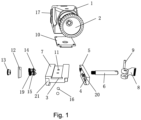
- FIG. 1 is a structural perspective diagram of a movable position-limiting quick-release gun light that can be moved according to the present application;
- FIG. 2 is an exploded structure diagram of the movable position-limiting quick-release gun light according to the present application
- FIG. 3 is a schematic three-dimensional structure diagram of the tightening nut of the movable position-limiting quick-release gun light according to the present application;
- FIG. 4 is a schematic three-dimensional structure diagram of the ejector rod of the movable position-limiting quick-release gun light according to the present application;
- FIG. 5 is a schematic three-dimensional structural diagram of the tightening rod of the movable position-limiting quick-release gun light according to the present application
- FIG. 6 is a schematic three-dimensional structural diagram of the tightening handle of the movable position-limiting quick-release gun light according to the present application.
- connection should be understood in a broad sense, for example, it can be a fixed connection or a detachable connection, or integrally connected; it can be a mechanical connection or an electrical connection; it can be directly connected, or indirectly connected through an intermediate medium, and it can be the internal communication between two components.
- installation and “connection” should be understood in a broad sense, for example, it can be a fixed connection or a detachable connection, or integrally connected; it can be a mechanical connection or an electrical connection; it can be directly connected, or indirectly connected through an intermediate medium, and it can be the internal communication between two components.
- the movable position-limiting quick-release gun light comprises a light main body 1 , wherein a support plate 10 is fixedly connected to the bottom end of the light main body 1 , and the left and right sides of the support plate 10 are slidably connected to the top of a base 7 , the connection between the light main body 1 and the base 7 is realized through the connection between the support plate 10 and the base 7 .
- a fixing plate 21 is fixedly connected to the left side of the bottom end of the base 7 , and the middle part of the fixing plate 21 is fixedly connected to a tightening seat 12 , and a baffle plate 5 is fixedly connected to the right side of the bottom end of the base 7 , and the middle part of the right end of the tightening seat 12 is fixedly connected to the left end of the tightening rod 6 , the right end of the tightening rod 6 is rotatably connected with a tightening handle 8 through a rotating shaft 9 , and the front and rear parts of the right end of the tightening seat 12 are fixedly connected to the left end of a ejector rod 14 .
- the tightening handle 8 When it is necessary to install the light, the tightening handle 8 is pulled outward, and the tightening rod 6 and the tightening seat 12 are in an open state, and then the tightening rod 12 is opened to drive the ejector rod 14 to separate from the corresponding round ball 16 .
- the baffle plates 5 on both sides are also in a loose state, and the light main body is relatively easy to slide relative to the gun body, and the base 7 used to fix the support plate 10 and the gun can be flexibly slid to adjust the position.
- Ball grooves 11 are evenly distributed in the middle of the top end of the base 7
- two round balls 16 are arranged inside the ball grooves 11
- limiting grooves 18 are evenly distributed at the bottom end of the support plate 10 .
- the limiting grooves 18 are located directly above the round balls 16
- the two round balls 16 are located in the corresponding limiting grooves 18 respectively.
- the round balls 16 will enter different limiting grooves 18 during the rolling process.
- the front end of the light main body 1 is fixedly connected with a light head 2 .
- the inside of the light head 2 is provided with a light bulb for lighting.
- the middle part of the top end of the base 7 is provided with a snap slot 3 , and the left and right ends of the support plate 10 are configured to slidably connect to the snap slot 3 .
- the left and right ends of the support plate 10 slide in the snap slot 3 , which facilitates the assembly and disassembly of the light main body 1 and the base 7 .
- the inner side of the baffle plate 5 and the inner side of the fixing plate 21 are provided with chute 4 , the sliding connection with the gun body is realized through the chute 4 .
- a stopper spring 20 is provided on the left side of the baffle plate 5 and the tightness of the baffle plate 5 is adjusted through the stopper spring 20 .
- the tightening rod 6 is configured to vertically penetrate the right baffle plate 5 .
- the left end of the tightening seat 12 is provided with a tightening nut 13 , the function of which is to adjust the tightening rod 6 to achieve an ideal tightening or loosening state.
- the outer periphery middle of the ejector rod 14 is provided with a push rod spring 15 , and the tightening seat 12 generates elastic force by pushing the push rod spring 15 to push the ejector rod 14 .
- a push rod nut 19 is provided on the left part of the outer periphery of the ejector rod 14 , and the tightness of the push rod spring 15 is adjusted through the push rod nut 19 .
- the left end of the light main body 1 is fixedly connected with a switch button 17 , and the light and dark of the light are controlled by the switch button 17 .
- Ball grooves 11 are evenly distributed in the middle of the top end of the base 7 , two round balls 16 are arranged inside the ball grooves 11 , and limiting grooves 18 are evenly distributed at the bottom end of the support plate 10 .
- the limiting grooves 18 are located directly above the round balls 16 , and the two round balls 16 are located in the corresponding limiting grooves 18 respectively. The round balls 16 will enter different limiting grooves 18 during the rolling process.
- the structure is simple, the maintenance and disassembly are convenient, and the use is very convenient.
Landscapes
- Engineering & Computer Science (AREA)
- General Engineering & Computer Science (AREA)
- Physics & Mathematics (AREA)
- Optics & Photonics (AREA)
- Coating Apparatus (AREA)
- Non-Portable Lighting Devices Or Systems Thereof (AREA)
Abstract
A movable position-limiting quick-release gun light, comprising a light main body, a bottom end of the light main body is fixedly connected with a support plate, and the left and right sides of which are slidable connected to the top of a base, the middle part of the fixing plate is fixedly connected with a tightening seat, the middle part of the right end of which is fixedly connected to the left end of the tightening rod, and the right end of which is rotatably connected with an tightening handle through a rotating shaft, the front and rear parts of the right end of the tightening seat are fixedly connected to the left end of the ejector rod. The structure of the gun light is simple, the maintenance and disassembly are easy, and the use is very convenient.
Description
This application claims the benefit and priority of Chinese patent application No. 202220070501.7, filed on Jan. 12, 2022, disclosure of which is hereby incorporated by reference in its entirety.
The present application relates to the technical field of lighting fixtures, and in particular, to a movable position-limiting quick-release gun light.
Lighting fixtures are a general term for lighting tools, which refer to appliances that can transmit light, distribute, and change the light distribution of light sources, including all parts except the light source for fixing and protecting the light source, as well as the wiring accessories necessary for connection with the power supply. Some guns are equipped with gun lights for use.
Gun lights are required to be easy to be assembled and disassembled. The disadvantages of traditional guns are as follows: first, the lights are installed by sliding rails and fixed by friction. During the installation process, the friction is large and not smooth, and there is no locking mechanism after installation, the lighting is easy to slide, and the second is that the position limiting method is to use the sawtooth slide rail to limit the position, which is relatively complicated, not easy to disassemble, high cost, and inconvenient to use.
The purpose of this application is to propose a movable limit quick release gun light in order to solve the shortcomings in the prior art.
In order to achieve the above object, the application adopts the following technical solutions: A movable position-limiting quick-release gun light comprises a light main body, wherein a support plate is fixedly connected to the bottom end of the light main body, and the left and right sides of the support plate are slidably connected to the top of a base, a fixing plate is fixedly connected to the left side of the bottom end of the base, and the middle part of the fixing plate is fixedly connected to a tightening seat, and baffle plates are fixedly connected to the right side of the bottom end of the base, and the middle part of the right end of the tightening seat is fixedly connected to the left end of the tightening rod, the right end of the tightening rod is rotatably connected with a tightening handle through a rotating shaft, and the front and rear parts of the right end of the tightening seat are fixedly connected to the left end of a ejector rod, ball grooves are evenly distributed in the middle of the top end of the base, two round balls are arranged inside the ball groove, and limiting grooves are evenly distributed at the bottom end of the support plate.
As a further description of the above technical solution: the front end of the light main body is fixedly connected with a light head.
As a further description of the above technical solution: the middle part of the top end of the base is provided with a snap slot, and the left and right ends of the support plate are configured to slidably connect to the snap slot.
As a further description of the above technical solution: the inner side of the baffle plate and the inner side of the fixing plate are provided with chute, the left side of the baffle plate is provided with a stopper spring.
As a further description of the above technical solution: the tightening rod is configured to vertically penetrate the right baffle plate.
As a further description of the above technical solution: the left end of the tightening seat is provided with a tightening nut.
As a further description of the above technical solution: a push rod spring is provided in the outer periphery middle of the ejector rod, and a push rod nut is provided on the left part of the outer periphery of the ejector rod.
As a further description of the above technical solution: a switch button is fixedly connected to the left end of the light main body.
This application has the following beneficial effects:
1. In this application, firstly, when it is necessary to install the light, the tightening handle is pulled outward, and the tightening rod and the tightening seat are in an open state, and then the tightening rod is opened to drive the ejector rod to separate from the corresponding round ball. At this time, the baffle plate is in a loose state, the light main body is relatively easy to slide relative to the gun body, and the base used to fix the support plate and the gun can be flexibly slid to adjust the position. After the adjustment is completed, move the tightening handle inward, the tightening rod drives the tightening seat to move, and the tightening seat pushes the ejector rod against the metal ball to prevent it from rolling, so as to achieve the purpose of locking, and it is very convenient to use.
2. In this application, first, two ball grooves are arranged in the middle of the top of the base, and two round balls are placed in the ball grooves, and then a row of limiting grooves are arranged at the bottom end of the support plate, and the limiting grooves are located directly above the round balls, and the two round balls are located in the corresponding limiting grooves respectively, and finally the round balls will enter different limiting grooves during the rolling process. By arranging the position where the round ball is located in the limiting groove, the purpose of moving and limiting the light main body relative to the base is achieved, the structure is simple, the maintenance and disassembly are convenient, and the use is very convenient.
1. Light main body; 2. Light head; 3. Snap slot; 4. Chute; 5. Baffle plate; 6. Tightening rod; 7. Base; 8. Tightening handle; 9. Rotating shaft; 10. Support plate; 11. Ball groove; 12. Tightening seat; 13. Tightening nut; 14. Ejector rod; 15. Push rod spring; 16. Round ball; 17. Switch button; 18. Limiting groove; 19. Push rod nut; 20. Stopper spring; 21. Fixing plate
The technical solutions in the embodiments of the present application will be clearly and completely described below with reference to the drawings in the embodiments of the present application. Obviously, the described embodiments are only a part of the embodiments of the present application, rather than all the embodiments. Based on the embodiments in the present application, all other embodiments obtained by those of ordinary skill in the art without creative efforts shall fall within the protection scope of the present application.
In the description of the present application, it should be noted that the terms “center”, “upper”, “lower”, “left”, “right”, “vertical”, “horizontal”, “inner”, “outer”, etc. which are used to indicate position or positional relationship are based on the position or positional relationship shown in the drawings, and are only for the convenience of describing the application and simplifying the description, rather than indicating or implying that the indicated position or element must have a specific orientation and be constructed in a specific orientation and operation, therefore cannot be understood as a limitation of the present application. The terms “first”, “second”, “third” are used for descriptive purposes only and should not be construed to indicate or imply relative importance. It should be noted that unless otherwise clearly specified and limited, the terms “installation”, and “connection” should be understood in a broad sense, for example, it can be a fixed connection or a detachable connection, or integrally connected; it can be a mechanical connection or an electrical connection; it can be directly connected, or indirectly connected through an intermediate medium, and it can be the internal communication between two components. For those skilled in the art, the specific meaning of the above-mentioned terms in the present application can be understood according to the specific circumstances.
Referring to FIGS. 1-6 , the movable position-limiting quick-release gun light comprises a light main body 1, wherein a support plate 10 is fixedly connected to the bottom end of the light main body 1, and the left and right sides of the support plate 10 are slidably connected to the top of a base 7, the connection between the light main body 1 and the base 7 is realized through the connection between the support plate 10 and the base 7. A fixing plate 21 is fixedly connected to the left side of the bottom end of the base 7, and the middle part of the fixing plate 21 is fixedly connected to a tightening seat 12, and a baffle plate 5 is fixedly connected to the right side of the bottom end of the base 7, and the middle part of the right end of the tightening seat 12 is fixedly connected to the left end of the tightening rod 6, the right end of the tightening rod 6 is rotatably connected with a tightening handle 8 through a rotating shaft 9, and the front and rear parts of the right end of the tightening seat 12 are fixedly connected to the left end of a ejector rod 14. When it is necessary to install the light, the tightening handle 8 is pulled outward, and the tightening rod 6 and the tightening seat 12 are in an open state, and then the tightening rod 12 is opened to drive the ejector rod 14 to separate from the corresponding round ball 16. The baffle plates 5 on both sides are also in a loose state, and the light main body is relatively easy to slide relative to the gun body, and the base 7 used to fix the support plate 10 and the gun can be flexibly slid to adjust the position. After the adjustment is completed, move the tightening handle 8 inward, the tightening rod 16 drives the tightening seat 12 to move, and the tightening seat 12 pushes the ejector rod 14 against the round ball 16 to prevent it from rolling, so as to achieve the purpose of locking. Ball grooves 11 are evenly distributed in the middle of the top end of the base 7, two round balls 16 are arranged inside the ball grooves 11, and limiting grooves 18 are evenly distributed at the bottom end of the support plate 10. The limiting grooves 18 are located directly above the round balls 16, and the two round balls 16 are located in the corresponding limiting grooves 18 respectively. The round balls 16 will enter different limiting grooves 18 during the rolling process. By arranging the position where the round ball 16 is located in the limiting groove 18, the purpose of moving and limiting the light main body 1 relative to the base 7 is achieved.
The front end of the light main body 1 is fixedly connected with a light head 2. The inside of the light head 2 is provided with a light bulb for lighting. The middle part of the top end of the base 7 is provided with a snap slot 3, and the left and right ends of the support plate 10 are configured to slidably connect to the snap slot 3. The left and right ends of the support plate 10 slide in the snap slot 3, which facilitates the assembly and disassembly of the light main body 1 and the base 7. The inner side of the baffle plate 5 and the inner side of the fixing plate 21 are provided with chute 4, the sliding connection with the gun body is realized through the chute 4. A stopper spring 20 is provided on the left side of the baffle plate 5 and the tightness of the baffle plate 5 is adjusted through the stopper spring 20. The tightening rod 6 is configured to vertically penetrate the right baffle plate 5. The left end of the tightening seat 12 is provided with a tightening nut 13, the function of which is to adjust the tightening rod 6 to achieve an ideal tightening or loosening state. The outer periphery middle of the ejector rod 14 is provided with a push rod spring 15, and the tightening seat 12 generates elastic force by pushing the push rod spring 15 to push the ejector rod 14. A push rod nut 19 is provided on the left part of the outer periphery of the ejector rod 14, and the tightness of the push rod spring 15 is adjusted through the push rod nut 19. The left end of the light main body 1 is fixedly connected with a switch button 17, and the light and dark of the light are controlled by the switch button 17.
Working principle: when it is necessary to install the light, the tightening handle 8 is pulled outward, and the tightening rod 6 and the tightening seat 12 are in an open state, and then the tightening rod 12 is opened to drive the ejector rod 14 to separate from the corresponding round ball 16. The baffle plates 5 on both sides are also in a loose state, and the light main body is relatively easy to slide relative to the gun body, and the base 7 used to fix the support plate 10 and the gun can be flexibly slid to adjust the position. After the adjustment is completed, move the tightening handle 8 inward, the tightening rod 16 drives the tightening seat 12 to move, and the tightening seat 12 pushes the ejector rod 14 against the round ball 16 to prevent it from rolling, so as to achieve the purpose of locking. Ball grooves 11 are evenly distributed in the middle of the top end of the base 7, two round balls 16 are arranged inside the ball grooves 11, and limiting grooves 18 are evenly distributed at the bottom end of the support plate 10. The limiting grooves 18 are located directly above the round balls 16, and the two round balls 16 are located in the corresponding limiting grooves 18 respectively. The round balls 16 will enter different limiting grooves 18 during the rolling process. By arranging the position where the round ball 16 is located in the limiting groove 18, the purpose of moving and limiting the light main body 1 relative to the base 7 is achieved, the structure is simple, the maintenance and disassembly are convenient, and the use is very convenient.
Finally, it should be noted that: the above are only the illustrative embodiments of the present application and are not intended to limit the application. Although the present application has been described in detail with reference to the foregoing embodiments, for those skilled in the art, they can still modify the technical solutions described in the foregoing embodiments, or perform equivalent replacements to some of the technical features. Therefore, any modification, equivalent replacement, improvement, etc., made to the above embodiments based on the actual technology of the present application still fall within the scope of the technical solution of the present application.
Claims (8)
1. A movable position-limiting quick-release gun light comprising:
a light main body, characterized in that a support plate is fixedly connected to the bottom end of the light main body, and the left and right sides of the support plate are slidably connected to the top of a base, a fixing plate is fixedly connected to the left side of the bottom end of the base, and the middle part of the fixing plate is fixedly connected to a tightening seat, and baffle plates are fixedly connected to the right side of the bottom end of the base, and the middle part of the right end of the tightening seat is fixedly connected to the left end of the tightening rod, the right end of the tightening rod is rotatably connected with a tightening handle through a rotating shaft, and the front and rear parts of the right end of the tightening seat are fixedly connected to the left end of a ejector rod, ball grooves are evenly distributed in the middle of the top end of the base, two round balls are arranged inside the ball grooves, and limiting grooves are evenly distributed at the bottom end of the support plate.
2. The movable position-limiting quick-release gun light as recited in claim 1 , wherein the front end of the light main body is fixedly connected with a light head.
3. The movable position-limiting quick-release gun light as recited in claim 1 , wherein the middle part of the top end of the base is provided with a snap slot, and the left and right ends of the support plate are configured to slidably connect to the snap slot.
4. The movable position-limiting quick-release gun light as recited in claim 1 , wherein the inner side of the baffle plate and the inner side of the fixing plate are provided with chute, the left side of the baffle plate is provided with a stopper spring.
5. The movable position-limiting quick-release gun light as recited in claim 1 , wherein the tightening rod is configured to vertically penetrate the right baffle plate.
6. The movable position-limiting quick-release gun light as recited in claim 1 , wherein the left end of the tightening seat is provided with a tightening nut.
7. The movable position-limiting quick-release gun light as recited in claim 1 , wherein a push rod spring is provided in the outer periphery middle of the ejector rod, and a push rod nut is provided on the left part of the outer periphery of the ejector rod.
8. The movable position-limiting quick-release gun light as recited in claim 1 , wherein a switch button is fixedly connected to the left end of the light main body.
Applications Claiming Priority (2)
| Application Number | Priority Date | Filing Date | Title |
|---|---|---|---|
| CN202220070501.7 | 2022-01-12 | ||
| CN202220070501.7U CN216385278U (en) | 2022-01-12 | 2022-01-12 | Movable limiting quick-release gun lamp |
Publications (1)
| Publication Number | Publication Date |
|---|---|
| US11578946B1 true US11578946B1 (en) | 2023-02-14 |
Family
ID=81237456
Family Applications (1)
| Application Number | Title | Priority Date | Filing Date |
|---|---|---|---|
| US17/666,682 Active US11578946B1 (en) | 2022-01-12 | 2022-02-08 | Movable position-limiting quick-release gun light |
Country Status (2)
| Country | Link |
|---|---|
| US (1) | US11578946B1 (en) |
| CN (1) | CN216385278U (en) |
Cited By (4)
| Publication number | Priority date | Publication date | Assignee | Title |
|---|---|---|---|---|
| US20220397370A1 (en) * | 2021-06-09 | 2022-12-15 | Hamskea Archery Solutions Llc | Arrow rest device |
| US11802658B1 (en) * | 2022-11-04 | 2023-10-31 | Wen-Shao Huang | Engagement structure of connection system |
| USD1008402S1 (en) * | 2022-02-24 | 2023-12-19 | Shenzhen Xinyue Han Technology Co., Ltd. | Laser sight |
| CN119797488A (en) * | 2025-02-14 | 2025-04-11 | 深圳市天广亿科技有限公司 | Ultraviolet disinfection device for sewage treatment |
Citations (25)
| Publication number | Priority date | Publication date | Assignee | Title |
|---|---|---|---|---|
| US2963789A (en) * | 1959-01-30 | 1960-12-13 | High Standard Mfg Corp | Sight for firearm |
| US4742636A (en) * | 1986-02-11 | 1988-05-10 | Eastman Kodak Company | Mount for mounting an optical sight on a firearm |
| US7185862B1 (en) * | 2005-10-04 | 2007-03-06 | Jen Yu Yang | Mounting platform assembly for a stand device |
| US7204052B2 (en) * | 2004-01-23 | 2007-04-17 | Swan Richard E | Detachable mount for a telescopic firearm sight |
| US20110042535A1 (en) * | 2009-08-18 | 2011-02-24 | Ming-Chung Cheng | Positioning apparatus for optical instrument |
| US8151511B2 (en) * | 2010-04-08 | 2012-04-10 | Beretta Usa Corp. | Gun sight mount for pistols |
| US8151508B1 (en) * | 2011-03-15 | 2012-04-10 | Moore Robert L | Rifle scope alignment device |
| US8438965B2 (en) * | 2009-09-23 | 2013-05-14 | OptiFlow, Inc. | Mounting device for weapon |
| US20130156495A1 (en) * | 2010-08-31 | 2013-06-20 | Zhuhai Chunqiu Optical Instruments Co., Ltd. | Eccentric handle device |
| US20140093314A1 (en) * | 2011-12-09 | 2014-04-03 | Kessler Crane, Inc. | Quick release plate |
| US20140252187A1 (en) * | 2013-02-05 | 2014-09-11 | Cody Petrovic | Modular mounting system using picatinny-type rail |
| US9217621B2 (en) * | 2010-08-31 | 2015-12-22 | Zhuhai Chunqiu Optical Instruments Co., Ltd. | Turning holder |
| US9297616B2 (en) * | 2010-12-31 | 2016-03-29 | Daniel Defense, Inc. | Systems and methods for associating an accessory with a firearm |
| US9568281B1 (en) * | 2014-01-02 | 2017-02-14 | Xiao Ming Chen | Quick locking system |
| US9677853B2 (en) * | 2015-03-05 | 2017-06-13 | GRS Riflestocks AS | Mount for a telescopic sight |
| US10030939B2 (en) * | 2015-07-28 | 2018-07-24 | Crosman Corporation | Adjustable rail mounting system |
| US10036614B1 (en) * | 2017-01-28 | 2018-07-31 | AIM Sports Inc. | Quick release mechanisms to attach accessories to firearms |
| US10365069B1 (en) * | 2018-03-30 | 2019-07-30 | Battenfeld Technologies, Inc. | Firearm accessory having firearm mount |
| US10443985B2 (en) * | 2017-05-23 | 2019-10-15 | Steiner E-Optics, Inc. | Kinematic rail mount for mounting a device on a firearm rail |
| US10563955B2 (en) * | 2017-01-17 | 2020-02-18 | Meprolight (1990) Ltd. | Small fire-arm sight mount |
| US10801814B2 (en) * | 2019-01-14 | 2020-10-13 | Shenzhen Olight E-Commerce Technology Co., Ltd. | Gun mounted light capable of position adjustment |
| US10907937B1 (en) * | 2019-08-23 | 2021-02-02 | Keng's Firearms Specialty, Inc. | Firearm mount and clamp assembly |
| US20210140743A1 (en) * | 2021-01-21 | 2021-05-13 | Xiaowei Chen | Weapon light |
| US20210223003A1 (en) * | 2020-01-17 | 2021-07-22 | Sig Sauer, Inc. | Adjustable firearm accessory |
| US20220282956A1 (en) * | 2021-03-02 | 2022-09-08 | Ningbo Acehawky Outdoor Products Technology Co., Ltd. | Rapid Clamping Mechanism Used For Pic Rail Connector |
-
2022
- 2022-01-12 CN CN202220070501.7U patent/CN216385278U/en not_active Expired - Fee Related
- 2022-02-08 US US17/666,682 patent/US11578946B1/en active Active
Patent Citations (27)
| Publication number | Priority date | Publication date | Assignee | Title |
|---|---|---|---|---|
| US2963789A (en) * | 1959-01-30 | 1960-12-13 | High Standard Mfg Corp | Sight for firearm |
| US4742636A (en) * | 1986-02-11 | 1988-05-10 | Eastman Kodak Company | Mount for mounting an optical sight on a firearm |
| US7204052B2 (en) * | 2004-01-23 | 2007-04-17 | Swan Richard E | Detachable mount for a telescopic firearm sight |
| US7185862B1 (en) * | 2005-10-04 | 2007-03-06 | Jen Yu Yang | Mounting platform assembly for a stand device |
| US20110042535A1 (en) * | 2009-08-18 | 2011-02-24 | Ming-Chung Cheng | Positioning apparatus for optical instrument |
| US8438965B2 (en) * | 2009-09-23 | 2013-05-14 | OptiFlow, Inc. | Mounting device for weapon |
| US8151511B2 (en) * | 2010-04-08 | 2012-04-10 | Beretta Usa Corp. | Gun sight mount for pistols |
| US9217621B2 (en) * | 2010-08-31 | 2015-12-22 | Zhuhai Chunqiu Optical Instruments Co., Ltd. | Turning holder |
| US20130156495A1 (en) * | 2010-08-31 | 2013-06-20 | Zhuhai Chunqiu Optical Instruments Co., Ltd. | Eccentric handle device |
| US9297616B2 (en) * | 2010-12-31 | 2016-03-29 | Daniel Defense, Inc. | Systems and methods for associating an accessory with a firearm |
| US8151508B1 (en) * | 2011-03-15 | 2012-04-10 | Moore Robert L | Rifle scope alignment device |
| US8827219B2 (en) * | 2011-12-09 | 2014-09-09 | Kessler Crane, Inc. | Quick release plate |
| US20140093314A1 (en) * | 2011-12-09 | 2014-04-03 | Kessler Crane, Inc. | Quick release plate |
| US20140252187A1 (en) * | 2013-02-05 | 2014-09-11 | Cody Petrovic | Modular mounting system using picatinny-type rail |
| US9568281B1 (en) * | 2014-01-02 | 2017-02-14 | Xiao Ming Chen | Quick locking system |
| US9677853B2 (en) * | 2015-03-05 | 2017-06-13 | GRS Riflestocks AS | Mount for a telescopic sight |
| US10030939B2 (en) * | 2015-07-28 | 2018-07-24 | Crosman Corporation | Adjustable rail mounting system |
| US10563955B2 (en) * | 2017-01-17 | 2020-02-18 | Meprolight (1990) Ltd. | Small fire-arm sight mount |
| US10684100B2 (en) * | 2017-01-17 | 2020-06-16 | Meprolight (1990) Ltd | Small fire-arm sight mount |
| US10036614B1 (en) * | 2017-01-28 | 2018-07-31 | AIM Sports Inc. | Quick release mechanisms to attach accessories to firearms |
| US10443985B2 (en) * | 2017-05-23 | 2019-10-15 | Steiner E-Optics, Inc. | Kinematic rail mount for mounting a device on a firearm rail |
| US10365069B1 (en) * | 2018-03-30 | 2019-07-30 | Battenfeld Technologies, Inc. | Firearm accessory having firearm mount |
| US10801814B2 (en) * | 2019-01-14 | 2020-10-13 | Shenzhen Olight E-Commerce Technology Co., Ltd. | Gun mounted light capable of position adjustment |
| US10907937B1 (en) * | 2019-08-23 | 2021-02-02 | Keng's Firearms Specialty, Inc. | Firearm mount and clamp assembly |
| US20210223003A1 (en) * | 2020-01-17 | 2021-07-22 | Sig Sauer, Inc. | Adjustable firearm accessory |
| US20210140743A1 (en) * | 2021-01-21 | 2021-05-13 | Xiaowei Chen | Weapon light |
| US20220282956A1 (en) * | 2021-03-02 | 2022-09-08 | Ningbo Acehawky Outdoor Products Technology Co., Ltd. | Rapid Clamping Mechanism Used For Pic Rail Connector |
Cited By (4)
| Publication number | Priority date | Publication date | Assignee | Title |
|---|---|---|---|---|
| US20220397370A1 (en) * | 2021-06-09 | 2022-12-15 | Hamskea Archery Solutions Llc | Arrow rest device |
| USD1008402S1 (en) * | 2022-02-24 | 2023-12-19 | Shenzhen Xinyue Han Technology Co., Ltd. | Laser sight |
| US11802658B1 (en) * | 2022-11-04 | 2023-10-31 | Wen-Shao Huang | Engagement structure of connection system |
| CN119797488A (en) * | 2025-02-14 | 2025-04-11 | 深圳市天广亿科技有限公司 | Ultraviolet disinfection device for sewage treatment |
Also Published As
| Publication number | Publication date |
|---|---|
| CN216385278U (en) | 2022-04-26 |
Similar Documents
| Publication | Publication Date | Title |
|---|---|---|
| US11578946B1 (en) | Movable position-limiting quick-release gun light | |
| CN204467482U (en) | A kind of detachable adjustable drawer front panel locking device | |
| CN103844674A (en) | Position regulating mechanism for drawer | |
| WO2016065670A1 (en) | Driver bit push-pull-type mounting/unmounting tool | |
| US12085261B2 (en) | Luminaire | |
| CN221375551U (en) | Bearing support and lighting equipment | |
| CN218447100U (en) | Arc lock for assembling display screen box | |
| CN103142042B (en) | Height adjusting mechanism for accurate positioning of drawer slide | |
| CN215982278U (en) | Intelligent lamp integrating film and television illumination and eye protection effects | |
| CN210068779U (en) | Manual bearing assembling device | |
| CN111457786B (en) | Positioning structure of telescopic support | |
| CN210328283U (en) | High-power supply easy to install and maintain | |
| CN203723702U (en) | Position adjusting mechanism for drawer | |
| CN222927908U (en) | Improved structure of socket | |
| CN111928075A (en) | 5G energy-saving emergency distribution and control ball | |
| CN223415928U (en) | A two-dimensional handle connector with longitudinal adjustment function | |
| CN216383766U (en) | Floor lamp with high stability | |
| CN222927909U (en) | Socket with sliding cover | |
| CN219639858U (en) | Clamping support | |
| CN223682207U (en) | Slide rail type height-adjusting seat tray | |
| CN222614004U (en) | Transmission line safety warning device | |
| CN218327804U (en) | Outdoor waterproof projection lamp | |
| CN223191498U (en) | Double-effect limiting connection track lamp with easily replaced light source and free of welding | |
| CN224005346U (en) | A cylindrical mirror adjustment mechanism | |
| CN217043314U (en) | Push rod length adjusting device of electric glue gun |
Legal Events
| Date | Code | Title | Description |
|---|---|---|---|
| FEPP | Fee payment procedure |
Free format text: ENTITY STATUS SET TO UNDISCOUNTED (ORIGINAL EVENT CODE: BIG.); ENTITY STATUS OF PATENT OWNER: MICROENTITY |
|
| FEPP | Fee payment procedure |
Free format text: ENTITY STATUS SET TO SMALL (ORIGINAL EVENT CODE: SMAL); ENTITY STATUS OF PATENT OWNER: MICROENTITY Free format text: ENTITY STATUS SET TO MICRO (ORIGINAL EVENT CODE: MICR); ENTITY STATUS OF PATENT OWNER: MICROENTITY |
|
| STCF | Information on status: patent grant |
Free format text: PATENTED CASE |