US11576510B1 - Submergible umbrella stand - Google Patents
Submergible umbrella stand Download PDFInfo
- Publication number
- US11576510B1 US11576510B1 US17/523,192 US202117523192A US11576510B1 US 11576510 B1 US11576510 B1 US 11576510B1 US 202117523192 A US202117523192 A US 202117523192A US 11576510 B1 US11576510 B1 US 11576510B1
- Authority
- US
- United States
- Prior art keywords
- submergible
- umbrella
- umbrella stand
- aperture
- sleeve
- Prior art date
- Legal status (The legal status is an assumption and is not a legal conclusion. Google has not performed a legal analysis and makes no representation as to the accuracy of the status listed.)
- Active
Links
- 229920001903 high density polyethylene Polymers 0.000 claims description 3
- 239000004700 high-density polyethylene Substances 0.000 claims description 3
- 229920001684 low density polyethylene Polymers 0.000 claims description 3
- 239000004702 low-density polyethylene Substances 0.000 claims description 3
- XLYOFNOQVPJJNP-UHFFFAOYSA-N water Substances O XLYOFNOQVPJJNP-UHFFFAOYSA-N 0.000 description 17
- 230000008901 benefit Effects 0.000 description 5
- 230000002093 peripheral effect Effects 0.000 description 5
- 230000009182 swimming Effects 0.000 description 5
- 238000004519 manufacturing process Methods 0.000 description 4
- 235000013361 beverage Nutrition 0.000 description 2
- 238000013037 co-molding Methods 0.000 description 2
- 229920001971 elastomer Polymers 0.000 description 2
- 239000000806 elastomer Substances 0.000 description 2
- 238000005516 engineering process Methods 0.000 description 2
- 239000000463 material Substances 0.000 description 2
- 229920003023 plastic Polymers 0.000 description 2
- 239000004033 plastic Substances 0.000 description 2
- 239000011347 resin Substances 0.000 description 2
- 229920005989 resin Polymers 0.000 description 2
- 238000006467 substitution reaction Methods 0.000 description 2
- 230000004075 alteration Effects 0.000 description 1
- 238000010276 construction Methods 0.000 description 1
- 239000007788 liquid Substances 0.000 description 1
- 239000000155 melt Substances 0.000 description 1
- 238000000034 method Methods 0.000 description 1
- 230000004048 modification Effects 0.000 description 1
- 238000012986 modification Methods 0.000 description 1
Images


Classifications
-
- A—HUMAN NECESSITIES
- A47—FURNITURE; DOMESTIC ARTICLES OR APPLIANCES; COFFEE MILLS; SPICE MILLS; SUCTION CLEANERS IN GENERAL
- A47G—HOUSEHOLD OR TABLE EQUIPMENT
- A47G25/00—Household implements used in connection with wearing apparel; Dress, hat or umbrella holders
- A47G25/12—Cane or umbrella stands or holders
-
- E—FIXED CONSTRUCTIONS
- E04—BUILDING
- E04H—BUILDINGS OR LIKE STRUCTURES FOR PARTICULAR PURPOSES; SWIMMING OR SPLASH BATHS OR POOLS; MASTS; FENCING; TENTS OR CANOPIES, IN GENERAL
- E04H12/00—Towers; Masts or poles; Chimney stacks; Water-towers; Methods of erecting such structures
- E04H12/22—Sockets or holders for poles or posts
- E04H12/2238—Sockets or holders for poles or posts to be placed on the ground
- E04H12/2246—Sockets or holders for poles or posts to be placed on the ground filled with water, sand or the like
-
- B—PERFORMING OPERATIONS; TRANSPORTING
- B63—SHIPS OR OTHER WATERBORNE VESSELS; RELATED EQUIPMENT
- B63B—SHIPS OR OTHER WATERBORNE VESSELS; EQUIPMENT FOR SHIPPING
- B63B22/00—Buoys
- B63B22/18—Buoys having means to control attitude or position, e.g. reaction surfaces or tether
- B63B22/20—Ballast means
-
- E—FIXED CONSTRUCTIONS
- E04—BUILDING
- E04H—BUILDINGS OR LIKE STRUCTURES FOR PARTICULAR PURPOSES; SWIMMING OR SPLASH BATHS OR POOLS; MASTS; FENCING; TENTS OR CANOPIES, IN GENERAL
- E04H4/00—Swimming or splash baths or pools
- E04H4/14—Parts, details or accessories not otherwise provided for
-
- Y—GENERAL TAGGING OF NEW TECHNOLOGICAL DEVELOPMENTS; GENERAL TAGGING OF CROSS-SECTIONAL TECHNOLOGIES SPANNING OVER SEVERAL SECTIONS OF THE IPC; TECHNICAL SUBJECTS COVERED BY FORMER USPC CROSS-REFERENCE ART COLLECTIONS [XRACs] AND DIGESTS
- Y10—TECHNICAL SUBJECTS COVERED BY FORMER USPC
- Y10S—TECHNICAL SUBJECTS COVERED BY FORMER USPC CROSS-REFERENCE ART COLLECTIONS [XRACs] AND DIGESTS
- Y10S248/00—Supports
- Y10S248/91—Weighted base
Definitions
- aspects of this invention relate generally to a submergible umbrella stand, and, in particular, to a submergible umbrella stand having a wall cavity configured to be filled with water and sealed to ensure the water level inside the unit doesn't equalize with the water outside the unit.
- Individuals may often float, swim, and stand in a swimming pool in order to cool off and socialize with others.
- the individuals may rest on inflatable devices that float in the pool.
- the individuals may also place stools, chairs, or other objects in the pool in order to provide seating and surfaces upon which to rest food and drinks.
- aspects of the present invention may be used to advantageously provide a submergible umbrella stand that can avoid being tipped over, and can provide a reservoir for storing ice.
- a submergible umbrella stand in accordance with a first aspect, includes a body including a top, a bottom spaced from the top, and a body wall extending between the top and the bottom and defining a body cavity therein. At least one filling aperture is formed in the top.
- An umbrella sleeve is positioned within the body and is configured to receive an umbrella pole.
- An upper recess is formed in the top and includes an upper recess sidewall extending inwardly and downwardly from the top of the body into the body cavity and a bottom extending inwardly from a bottom of the upper recess sidewall.
- a first sleeve aperture is formed in the bottom of the upper recess, with the umbrella sleeve extending through the first sleeve aperture
- a submergible umbrella stand includes a body including a top, a bottom spaced from the top, and a body wall extending between the top and the bottom and defining a body cavity therein.
- a pair of filling apertures is formed in the top.
- a pair of drain apertures is formed in the bottom.
- An upper recess is formed in the top of the body and includes an upper recess sidewall extending inwardly and downwardly from the top of the body into the body cavity and a bottom extending inwardly from a bottom of the upper recess sidewall, with a first sleeve aperture being formed in the bottom of the upper recess.
- a lower recess is formed in the bottom of the body and includes a lower recess sidewall extending inwardly and upwardly from the bottom of the body into the body cavity and a top extending inwardly from a top of the lower recess sidewall, with a second sleeve aperture being formed in the top of the lower recess.
- An umbrella sleeve extends vertically within the body through the first sleeve aperture and the second sleeve aperture.
- FIG. 1 is a perspective view of a submergible umbrella stand according to aspects of the disclosure, shown with an umbrella pole.
- FIG. 2 is a perspective view, in section, of the submergible umbrella stand of FIG. 1 .
- FIG. 3 is a section view of the submergible umbrella stand and umbrella pole of FIG. 1 .
- FIG. 4 is a perspective view, shown partially broken away, of a portion of the submergible umbrella stand of FIG. 1 , and a cover.
- FIG. 5 is a perspective view of an alternative embodiment of the submergible umbrella stand of FIG. 1 .
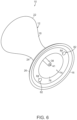
- FIG. 6 is a bottom perspective view of the submergible umbrella stand of FIG. 1 .
- FIG. 7 is a bottom perspective view of an alternative embodiment of the submergible umbrella stand of FIG. 1 .
- FIG. 8 is perspective view, shown partially broken away, of an alternative embodiment of the top of the submergible umbrella stand of FIG. 1 .
- FIG. 9 is a perspective view of the submergible umbrella stand of FIG. 1 , shown with a first insert raised to provide access the reservoir.
- FIG. 10 is a plan view of the top cover of the submergible umbrella stand of FIG. 1 .
- FIG. 11 is perspective view of an alternative embodiment of the submergible umbrella stand of FIG. 1 , shown with a top cover formed of two portions.
- FIG. 12 is a perspective view, in section, of an alternative embodiment of the submergible umbrella stand of FIG. 1 .
- FIGS. 1 - 3 An embodiment of a submergible umbrella stand 10 is shown in FIGS. 1 - 3 .
- terms such as upper, lower, top, bottom, front, and rear may be used herein to differentiate between the upper and lower ends and front and rear sides of submergible umbrella stand 10 and particular components of submergible umbrella stand 10 . It is to be appreciated that such terms are used only for ease of description and understanding and that they are not intended to limit the possible spatial orientations of the submergible umbrella stand or its components during assembly or use.
- Submergible umbrella stand 10 may include a body 12 including a top 14 , a bottom 16 spaced from top 14 , and a body wall 18 extending between top 14 and bottom 16 .
- Body wall 18 , top 14 , and bottom 16 may define a body cavity 20 contained therein.
- body 12 may have an hourglass shape with body wall 18 tapering inwardly from a top edge 22 thereof toward a central portion 24 of body 12 , and tapering outwardly from central portion 24 toward a bottom edge 26 thereof.
- Body 12 may have a top diameter T at top edge 22 of body wall 18 and a bottom diameter B at bottom edge 26 of body wall 18 .
- bottom diameter B is larger than top diameter T. It is to be appreciated that in other embodiments top diameter T could be larger than bottom diameter B, and in other embodiments top diameter T and bottom diameter B could have the same value.
- Bottom diameter B may be between approximately 22 inches and approximately 33 inches, and, more particularly, approximately 28 inches.
- Top diameter D may be between approximately 4 inches and approximately 28 inches.
- Body cavity 20 may contain liquid 28 , e.g., water, which may provide stability for submergible umbrella stand 10 when it is seated in water 30 , as seen in FIG. 3 , such as when submergible umbrella stand 10 is seated in a swimming pool.
- the maximum depth of water 30 in the pool is approximately 18 inches.
- Body cavity 20 may be partially or completely filled with water when submergible umbrella stand 10 is seated in a swimming pool.
- An umbrella pole 32 supporting an umbrella may be received in submergible umbrella stand 10 .
- water 28 in body cavity 20 may help prevent submergible umbrella stand 10 from tipping when the umbrella is subjected to high winds, as illustrated by arrow W.
- Water contained within body 12 ensures that it is very difficult to tip over submergible umbrella stand 10 .
- umbrella sleeve 34 configured to receive umbrella pole 32 may be positioned and extend vertically within body 12 of submergible umbrella stand 10 . As seen in FIGS. 2 - 3 , umbrella sleeve 34 may include an upper portion 36 and a lower portion 38 . A flange 37 may extend laterally outwardly about an upper edge of upper portion 36 of umbrella sleeve 34 .
- Lower portion 38 may be configured to receive a lowermost end portion 40 of umbrella pole 32
- upper portion 36 may be configured to receive a central portion 42 of umbrella pole 32
- An upper aperture 39 may be formed at an upper end of upper portion 36
- a lower aperture 41 may be formed at a lower end of lower portion 38 .
- Umbrella pole 32 may be inserted into umbrella sleeve 34 through upper aperture 39 .
- Upper portion 36 may be substantially cylindrical with a diameter U.
- upper portion 36 is tapered so as to easily receive an umbrella pole 32 having a diameter of approximately 2 inches.
- diameter U may be approximately 2.2 inches at a top end thereof, and taper to a diameter of approximately 1.8 inches at a lower end thereof.
- Such a tapered configuration for upper portion 36 may allow for an umbrella pole 32 having a diameter of approximately 2 inches to be become wedged and centered within upper portion 36 .
- a sleeve shoulder 44 may extend laterally between a lower edge of upper portion 36 and an upper edge of lower portion 38 of umbrella sleeve 34 .
- Lower portion 38 may be cylindrical with a diameter L.
- lower portion 38 is tapered so as to easily receive an umbrella pole 32 having a diameter of approximately 1.5 inches.
- diameter L may be approximately 1.7 inches at a top end thereof, and taper to a diameter of approximately 1.3 inches at a lower end thereof.
- Such a tapered configuration for lower portion 38 may allow for an umbrella pole 32 having a diameter of approximately 1.5 inches to be become wedged and centered within lower portion 38 .
- an upper recess 50 may be formed in top 14 of body 12 .
- Upper recess 50 may have an upper recess sidewall 52 and a bottom 54 .
- Upper recess sidewall 52 may taper inwardly from top 14 to bottom 54
- bottom 54 may extend radially inwardly from a bottom of upper recess sidewall 52 .
- a first sleeve aperture 58 may be formed in bottom 54
- umbrella sleeve 34 may extend through first sleeve aperture 58 .
- a peripheral edge of flange 37 may be secured to first sleeve aperture 58 .
- upper recess 50 may form a reservoir that can be filled with ice to keep beverages and other items cold for users in the swimming pool.
- the resulting water may pass into umbrella sleeve 34 through upper aperture 39 and out of umbrella sleeve 34 through lower aperture 41 .
- At least one filling aperture 59 may be formed in top 14 .
- Water may be introduced into body cavity 20 through each filling aperture 59 .
- two filling apertures 29 are formed in top 14 . It is to be appreciated that any number of filling apertures 59 may be formed in top 14 .
- a top cover 60 may rest on top 14 of body 12 , covering filling apertures 59 .
- Top cover 60 may include a central recess 62 and a central aperture 63 formed in a bottom 64 of central recess 62 .
- Central aperture 63 may receive umbrella pole 32 .
- a first insert 66 may be seated within central recess 62 , and first insert 66 may include a first pole aperture 68 configured to receive umbrella pole 32 .
- First pole aperture 68 may have a diameter P. In certain embodiments, diameter P may be approximately 2.05 inches so as to easily receive umbrella pole 32 having a diameter of approximately 2 inches.
- a second insert 70 may have a second pole aperture 72 , and may be configured to receive umbrella pole 32 .
- Second pole aperture 72 may have a diameter Q.
- diameter Q may be approximately 1.55 inches so as to easily receive umbrella pole 32 having a diameter of approximately 1.5 inches.
- top cover 60 , first insert 66 , and second insert 70 each may be formed of a resin, a plastic, or an elastomer.
- top cover 60 , first insert 66 , and second insert 70 may be formed of high density polyethylene (HDPE).
- HDPE high density polyethylene
- Other suitable materials for top cover 60 , first insert 66 , and second insert 70 will become readily apparent to those skilled in the art, given the benefit of this disclosure.
- a lower recess 74 may be formed in bottom 16 of body 12 .
- Lower recess 74 may have a lower recess sidewall 76 and a top 78 .
- Lower recess sidewall 76 may taper inwardly from bottom 16 to top 78
- top 78 may extend radially inwardly from a top of lower recess sidewall 76 .
- a second sleeve aperture 80 may be formed in top 78 , and umbrella sleeve 34 may extend through second sleeve aperture 80 .
- a lower end of upper portion 36 , and lower portion 38 of umbrella sleeve each may extend downwardly into and be received in lower recess 74 .
- Lower recess 74 may serve to reduce the amount of water captured within body cavity 20 so as to reduce the weight of submergible umbrella stand 10 , while still providing sufficient stability for submergible umbrella stand 10 , helping prevent it from tipping over when wind W engages the umbrella in depths of water up to approximately 18 inches.
- each of body 12 and umbrella sleeve 34 may be formed individually as molded parts, and then co-molded together.
- flange 37 of umbrella sleeve 34 may be secured to first sleeve aperture 58 in bottom 54 of upper recess 50 by co-molding, and a peripheral edge of upper portion 36 of umbrella sleeve 34 may be secured to second sleeve aperture 80 in top 78 of lower recess 74 by co-molding.
- body 12 and umbrella sleeve 34 may be formed of a resin, a plastic, or an elastomer.
- body 12 and umbrella sleeve 34 may be formed of low density polyethylene (LDPE).
- LDPE low density polyethylene
- Other suitable materials for body 12 and umbrella sleeve 34 will become readily apparent to those skilled in the art, given the benefit of this disclosure.
- one or more drain apertures 82 may be formed in bottom 16 , and may serve to help drain water from body cavity 20 .
- a drain cap 84 may be removably secured within each drain aperture 82 , which may serve to prevent the water from inadvertently draining from body cavity 20 .
- two drain apertures 82 are formed in bottom 16 , with drain caps 84 secured thereto. It is to be appreciated that any number of drain apertures 82 may be formed in bottom 16 .
- bottom 16 may be formed without lower recess 74 as seen in FIG. 2 .
- a central drain aperture 86 may be formed in a central portion of bottom 16 . Central drain aperture 86 may allow the water from melted ice that has passed through umbrella sleeve 34 to exit body 12 of submergible umbrella stand 10 .
- plugs 88 may be removably seated in filling apertures 59 . Plugs 88 may fit within filling apertures 59 in snap-fit fashion.
- first insert 66 (or second insert 70 ) may be lifted upwardly out of central recess 62 , allowing the user to access reservoir 50 and retrieve beverages or other items sitting on ice in reservoir 50 .
- a notch 90 may be formed in the periphery of central recess 62 , allowing the user to insert a finger beneath the peripheral edge of first insert 66 in order to lift it out of central recess 62 .
- top cover 60 may not include an insert, and umbrella pole 32 may be received directly in central recess 62 .
- top cover 60 may be formed of a first portion 92 and a second portion 94 .
- First portion 92 may be larger than second portion 94
- central recess 62 may be formed in first portion 92 .
- the user may lift second portion 94 upwardly away from body 12 .
- umbrella sleeve 34 and the remainder of body 12 may be formed of one-piece construction.
- the upper end of upper portion 36 of umbrella sleeve 34 may be directly connected to first sleeve aperture 58 .
- a collar 96 may be provided at the top of upper portion 36 .
- Collar 96 may include a collar aperture 98 through which umbrella pole 32 extends.
- a peripheral flange 100 may extend outwardly from the peripheral edge of collar 96 , and may be seated upon bottom 54 of reservoir 50 .
- umbrella pole 32 is anchored at two points along its length, namely at collar 96 and at is lowermost end where it engages the inner surface of upper portion 36 or the inner surface of lower portion 38 , each of which is tapered as described above. As illustrated here, where umbrella pole 32 has a two inch diameter, the lowermost end of umbrella pole engages the inner surface of lower portion 38 .
- submergible umbrella stand Various embodiments of a submergible umbrella stand have been described herein, which include various components and features. In other embodiments, the submergible umbrella stand may be provided with any combination of such components and features. It is also understood that in other embodiments, the various devices, components, and features of the submergible umbrella stand described herein may be constructed with similar structural and functional elements having different configurations, including different ornamental appearances.
Landscapes
- Engineering & Computer Science (AREA)
- Architecture (AREA)
- Chemical & Material Sciences (AREA)
- Civil Engineering (AREA)
- Structural Engineering (AREA)
- Chemical Kinetics & Catalysis (AREA)
- Combustion & Propulsion (AREA)
- Mechanical Engineering (AREA)
- Ocean & Marine Engineering (AREA)
- Holders For Apparel And Elements Relating To Apparel (AREA)
Abstract
A submergible umbrella stand includes a body including a top, a bottom spaced from the top, and a body wall extending between the top and the bottom and defining a body cavity therein. At least one filling aperture is formed in the top. An umbrella sleeve is positioned within the body and is configured to receive an umbrella pole. An upper recess is formed in the top and includes an upper recess sidewall extending inwardly and downwardly from the top of the body into the body cavity and a bottom extending inwardly from a bottom of the upper recess sidewall. A first sleeve aperture is formed in the bottom of the upper recess, with the umbrella sleeve extending through the first sleeve aperture.
Description
Aspects of this invention relate generally to a submergible umbrella stand, and, in particular, to a submergible umbrella stand having a wall cavity configured to be filled with water and sealed to ensure the water level inside the unit doesn't equalize with the water outside the unit.
Individuals may often float, swim, and stand in a swimming pool in order to cool off and socialize with others. The individuals may rest on inflatable devices that float in the pool. The individuals may also place stools, chairs, or other objects in the pool in order to provide seating and surfaces upon which to rest food and drinks.
It would be desirable to provide a submergible umbrella stand that can provide shade for individuals in a swimming pool, and to provide a surface upon which to rest food and drinks. Particular objects and advantages will be apparent to those skilled in the art, that is, those who are knowledgeable or experienced in this field of technology, in view of the following disclosure of the invention and detailed description of certain embodiments.
Aspects of the present invention may be used to advantageously provide a submergible umbrella stand that can avoid being tipped over, and can provide a reservoir for storing ice.
In accordance with a first aspect, a submergible umbrella stand includes a body including a top, a bottom spaced from the top, and a body wall extending between the top and the bottom and defining a body cavity therein. At least one filling aperture is formed in the top. An umbrella sleeve is positioned within the body and is configured to receive an umbrella pole. An upper recess is formed in the top and includes an upper recess sidewall extending inwardly and downwardly from the top of the body into the body cavity and a bottom extending inwardly from a bottom of the upper recess sidewall. A first sleeve aperture is formed in the bottom of the upper recess, with the umbrella sleeve extending through the first sleeve aperture
In accordance with another aspect, a submergible umbrella stand includes a body including a top, a bottom spaced from the top, and a body wall extending between the top and the bottom and defining a body cavity therein. A pair of filling apertures is formed in the top. A pair of drain apertures is formed in the bottom. An upper recess is formed in the top of the body and includes an upper recess sidewall extending inwardly and downwardly from the top of the body into the body cavity and a bottom extending inwardly from a bottom of the upper recess sidewall, with a first sleeve aperture being formed in the bottom of the upper recess. A lower recess is formed in the bottom of the body and includes a lower recess sidewall extending inwardly and upwardly from the bottom of the body into the body cavity and a top extending inwardly from a top of the lower recess sidewall, with a second sleeve aperture being formed in the top of the lower recess. An umbrella sleeve extends vertically within the body through the first sleeve aperture and the second sleeve aperture.
From the foregoing disclosure, it will be readily apparent to those skilled in the art, that is, those who are knowledgeable or experienced in this area of technology, that preferred embodiments of a submergible umbrella stand may provide a significant technological advance that allows the submergible umbrella stand to resist wind without tipping over, and provide a reservoir for ice. These and additional features and advantages will be further understood from the following detailed disclosure of certain preferred embodiments.
The figures referred to above are not drawn necessarily to scale and should be understood to provide a representation of umbrella stand, illustrative of the principles involved. Some features of the submergible umbrella stand depicted in the drawings have been enlarged or distorted relative to others to facilitate explanation and understanding. The same reference numbers are used in the drawings for similar or identical components and features shown in various alternative embodiments. Submergible umbrella stands as disclosed herein would have configurations and components determined, in part, by the intended application and environment in which they are used.
The present invention may be embodied in various forms. An embodiment of a submergible umbrella stand 10 is shown in FIGS. 1-3 . For convenience, terms such as upper, lower, top, bottom, front, and rear may be used herein to differentiate between the upper and lower ends and front and rear sides of submergible umbrella stand 10 and particular components of submergible umbrella stand 10. It is to be appreciated that such terms are used only for ease of description and understanding and that they are not intended to limit the possible spatial orientations of the submergible umbrella stand or its components during assembly or use.
The term “substantially”, as used herein, is meant to mean mostly, or almost the same as, within the constraints of sensible commercial engineering objectives, costs, manufacturing tolerances, and capabilities in the field of submergible umbrella stand manufacturing and use. Similarly, the term “approximately” as used herein is meant to mean close to, or about a particular value, within the constraints of sensible commercial engineering objectives, costs, manufacturing tolerances, and capabilities in the field of submergible umbrella stand manufacturing and use.
In certain embodiments, body 12 may have an hourglass shape with body wall 18 tapering inwardly from a top edge 22 thereof toward a central portion 24 of body 12, and tapering outwardly from central portion 24 toward a bottom edge 26 thereof.
Bottom diameter B may be between approximately 22 inches and approximately 33 inches, and, more particularly, approximately 28 inches. Top diameter D may be between approximately 4 inches and approximately 28 inches.
An umbrella pole 32 supporting an umbrella (not shown) may be received in submergible umbrella stand 10. As seen most clearly in FIG. 3 , water 28 in body cavity 20 may help prevent submergible umbrella stand 10 from tipping when the umbrella is subjected to high winds, as illustrated by arrow W. Water contained within body 12 ensures that it is very difficult to tip over submergible umbrella stand 10.
Such a configuration allows the umbrella on umbrella pole 32 to be secured in a stable stand, while submerged in water up to approximately 18 inches deep, without needing to provide an umbrella receiver in the floor or base of the pool. An umbrella sleeve 34 configured to receive umbrella pole 32 may be positioned and extend vertically within body 12 of submergible umbrella stand 10. As seen in FIGS. 2-3 , umbrella sleeve 34 may include an upper portion 36 and a lower portion 38. A flange 37 may extend laterally outwardly about an upper edge of upper portion 36 of umbrella sleeve 34.
A sleeve shoulder 44 may extend laterally between a lower edge of upper portion 36 and an upper edge of lower portion 38 of umbrella sleeve 34.
In certain embodiments, an upper recess 50 may be formed in top 14 of body 12. Upper recess 50 may have an upper recess sidewall 52 and a bottom 54. Upper recess sidewall 52 may taper inwardly from top 14 to bottom 54, and bottom 54 may extend radially inwardly from a bottom of upper recess sidewall 52. A first sleeve aperture 58 may be formed in bottom 54, and umbrella sleeve 34 may extend through first sleeve aperture 58. In certain embodiments, a peripheral edge of flange 37 may be secured to first sleeve aperture 58.
In certain embodiments, upper recess 50 may form a reservoir that can be filled with ice to keep beverages and other items cold for users in the swimming pool. When the ice in upper recess 50 melts, the resulting water may pass into umbrella sleeve 34 through upper aperture 39 and out of umbrella sleeve 34 through lower aperture 41.
As seen in FIG. 4 , at least one filling aperture 59 may be formed in top 14. Water may be introduced into body cavity 20 through each filling aperture 59. In the illustrated embodiment, two filling apertures 29 are formed in top 14. It is to be appreciated that any number of filling apertures 59 may be formed in top 14.
In certain embodiments, a top cover 60 may rest on top 14 of body 12, covering filling apertures 59. Top cover 60 may include a central recess 62 and a central aperture 63 formed in a bottom 64 of central recess 62. Central aperture 63 may receive umbrella pole 32.
As seen in FIG. 1 , a first insert 66 may be seated within central recess 62, and first insert 66 may include a first pole aperture 68 configured to receive umbrella pole 32. First pole aperture 68 may have a diameter P. In certain embodiments, diameter P may be approximately 2.05 inches so as to easily receive umbrella pole 32 having a diameter of approximately 2 inches.
In other embodiments, as illustrated in FIG. 5 , a second insert 70 may have a second pole aperture 72, and may be configured to receive umbrella pole 32. Second pole aperture 72 may have a diameter Q. In certain embodiments, diameter Q may be approximately 1.55 inches so as to easily receive umbrella pole 32 having a diameter of approximately 1.5 inches.
In certain embodiments, top cover 60, first insert 66, and second insert 70 each may be formed of a resin, a plastic, or an elastomer. For example, top cover 60, first insert 66, and second insert 70 may be formed of high density polyethylene (HDPE). Other suitable materials for top cover 60, first insert 66, and second insert 70 will become readily apparent to those skilled in the art, given the benefit of this disclosure.
In certain embodiments, as seen in FIGS. 2, 3, and 6 , a lower recess 74 may be formed in bottom 16 of body 12. Lower recess 74 may have a lower recess sidewall 76 and a top 78. Lower recess sidewall 76 may taper inwardly from bottom 16 to top 78, and top 78 may extend radially inwardly from a top of lower recess sidewall 76. A second sleeve aperture 80 may be formed in top 78, and umbrella sleeve 34 may extend through second sleeve aperture 80. In such an embodiment, a lower end of upper portion 36, and lower portion 38 of umbrella sleeve each may extend downwardly into and be received in lower recess 74.
In certain embodiments, each of body 12 and umbrella sleeve 34 may be formed individually as molded parts, and then co-molded together. Thus, flange 37 of umbrella sleeve 34 may be secured to first sleeve aperture 58 in bottom 54 of upper recess 50 by co-molding, and a peripheral edge of upper portion 36 of umbrella sleeve 34 may be secured to second sleeve aperture 80 in top 78 of lower recess 74 by co-molding.
In certain embodiments, body 12 and umbrella sleeve 34 may be formed of a resin, a plastic, or an elastomer. For example, body 12 and umbrella sleeve 34 may be formed of low density polyethylene (LDPE). Other suitable materials for body 12 and umbrella sleeve 34 will become readily apparent to those skilled in the art, given the benefit of this disclosure.
In certain embodiments, as illustrated in FIG. 6 , one or more drain apertures 82 may be formed in bottom 16, and may serve to help drain water from body cavity 20. A drain cap 84 may be removably secured within each drain aperture 82, which may serve to prevent the water from inadvertently draining from body cavity 20. In the illustrated embodiment, two drain apertures 82 are formed in bottom 16, with drain caps 84 secured thereto. It is to be appreciated that any number of drain apertures 82 may be formed in bottom 16.
In certain embodiments, as illustrated in FIG. 7 , bottom 16 may be formed without lower recess 74 as seen in FIG. 2 . In such an embodiment, a central drain aperture 86 may be formed in a central portion of bottom 16. Central drain aperture 86 may allow the water from melted ice that has passed through umbrella sleeve 34 to exit body 12 of submergible umbrella stand 10.
In certain embodiments, as illustrated in FIG. 8 , plugs 88 may be removably seated in filling apertures 59. Plugs 88 may fit within filling apertures 59 in snap-fit fashion.
In certain embodiments, as illustrated in FIGS. 9-10 , first insert 66 (or second insert 70) may be lifted upwardly out of central recess 62, allowing the user to access reservoir 50 and retrieve beverages or other items sitting on ice in reservoir 50. A notch 90 may be formed in the periphery of central recess 62, allowing the user to insert a finger beneath the peripheral edge of first insert 66 in order to lift it out of central recess 62.
In certain embodiments, as illustrated in FIG. 11 , top cover 60 may not include an insert, and umbrella pole 32 may be received directly in central recess 62. In such an embodiment, top cover 60 may be formed of a first portion 92 and a second portion 94. First portion 92 may be larger than second portion 94, and central recess 62 may be formed in first portion 92. To access reservoir 50 and its contents, the user may lift second portion 94 upwardly away from body 12.
In certain embodiments, as seen in FIG. 12 , umbrella sleeve 34 and the remainder of body 12 may be formed of one-piece construction. In such an embodiment, the upper end of upper portion 36 of umbrella sleeve 34 may be directly connected to first sleeve aperture 58. In such an embodiment, a collar 96 may be provided at the top of upper portion 36. Collar 96 may include a collar aperture 98 through which umbrella pole 32 extends. A peripheral flange 100 may extend outwardly from the peripheral edge of collar 96, and may be seated upon bottom 54 of reservoir 50. In such an embodiment umbrella pole 32 is anchored at two points along its length, namely at collar 96 and at is lowermost end where it engages the inner surface of upper portion 36 or the inner surface of lower portion 38, each of which is tapered as described above. As illustrated here, where umbrella pole 32 has a two inch diameter, the lowermost end of umbrella pole engages the inner surface of lower portion 38.
Various embodiments of a submergible umbrella stand have been described herein, which include various components and features. In other embodiments, the submergible umbrella stand may be provided with any combination of such components and features. It is also understood that in other embodiments, the various devices, components, and features of the submergible umbrella stand described herein may be constructed with similar structural and functional elements having different configurations, including different ornamental appearances.
Those having skill in the art, with the knowledge gained from the present disclosure, will recognize that various changes can be made to the disclosed apparatuses and methods in attaining these and other advantages, without departing from the scope of the present disclosure. As such, it should be understood that the features described herein are susceptible to modification, alteration, changes, or substitution. For example, it is expressly intended that all combinations of those elements and/or steps which perform substantially the same function, in substantially the same way, to achieve the same results are within the scope of the embodiments described herein. Substitutions of elements from one described embodiment to another are also fully intended and contemplated. The specific embodiments illustrated and described herein are for illustrative purposes only, and not limiting of that which is set forth in the appended claims. Other embodiments will be evident to those of skill in the art. It should be understood that the foregoing description is provided for clarity only and is merely exemplary. The spirit and scope of the present disclosure is not limited to the above examples, but is encompassed by the following claims.
Claims (19)
1. A submergible umbrella stand comprising:
a body including a top, a bottom spaced from the top, and a body wall extending between the top and the bottom and defining a body cavity therein;
a lower recess formed in the bottom of the body and including a lower recess sidewall extending inwardly and upwardly from the bottom of the body into the body cavity and a top extending inwardly from a top of the lower recess sidewall;
at least one filling aperture formed in the top;
an umbrella sleeve positioned within the body and configured to receive an umbrella pole;
an upper recess formed in the top and including an upper recess sidewall extending inwardly and downwardly from the top of the body into the body cavity and a bottom extending inwardly from a bottom of the upper recess sidewall; and
a first sleeve aperture formed in the bottom of the upper recess, the umbrella sleeve extending through the first sleeve aperture.
2. The submergible umbrella stand of claim 1 , further comprising a second sleeve aperture formed in the top of the lower recess, the umbrella sleeve extending through the second sleeve aperture.
3. The submergible umbrella stand of claim 1 , wherein the body wall tapers inwardly from a top edge thereof to a central portion thereof and tapers outwardly from the central portion to a bottom edge thereof.
4. The submergible umbrella stand of claim 1 , wherein the body is formed of low density polyethylene.
5. The submergible umbrella stand of claim 1 , further comprising a cover positioned on top of the body and including a central aperture formed therein, the central aperture configured to receive an umbrella pole.
6. The submergible umbrella stand of claim 5 , wherein the cover is formed of high density polyethylene.
7. The submergible umbrella stand of claim 5 , further comprising a central recess formed in the cover and including a sidewall and a bottom, the central aperture being formed in the bottom of the central recess.
8. The submergible umbrella stand of claim 7 , further comprising a first insert receivable in the central recess and having a first insert aperture formed therein.
9. The submergible umbrella stand of claim 7 , further comprising a second insert receivable in the central recess and having a second insert aperture formed therein.
10. The submergible umbrella stand of claim 1 , wherein two filling apertures are formed in the top of the body.
11. The submergible umbrella stand of claim 1 , further comprising at least one drain aperture formed in the bottom of the body.
12. The submergible umbrella stand of claim 1 , wherein a bottom diameter of the body is larger than a top diameter of the body.
13. The submergible umbrella stand of claim 1 , wherein the body is hourglass shaped.
14. The submergible umbrella stand of claim 1 , wherein the umbrella sleeve includes an upper portion and a lower portion.
15. The submergible umbrella stand of claim 14 , wherein the upper portion is tapered with a first diameter at an upper end thereof and a second diameter at a lower end thereof, the first diameter being larger than the second diameter.
16. The submergible umbrella stand of claim 14 , wherein the lower portion is tapered with a first diameter at an upper end thereof and a second diameter at a lower end thereof, the first diameter being larger than the second diameter.
17. The submergible umbrella stand of claim 14 , further comprising a collar positioned at an upper end of the upper portion.
18. The submergible umbrella stand of claim 17 , wherein the collar includes a collar aperture configured to receive an umbrella pole.
19. A submergible umbrella stand comprising:
a body including a top, a bottom spaced from the top, and a body wall extending between the top and the bottom and defining a body cavity therein;
a pair of filling apertures formed in the top;
a pair of drain apertures formed in the bottom;
an upper recess formed in the top of the body and including an upper recess sidewall extending inwardly and downwardly from the top of the body into the body cavity and a bottom extending inwardly from a bottom of the upper recess sidewall, a first sleeve aperture being formed in the bottom of the upper recess;
a lower recess formed in the bottom of the body and including a lower recess sidewall extending inwardly and upwardly from the bottom of the body into the body cavity and a top extending inwardly from a top of the lower recess sidewall, a second sleeve aperture being formed in the top of the lower recess; and
an umbrella sleeve extending vertically within the body through the first sleeve aperture and the second sleeve aperture.
Priority Applications (1)
| Application Number | Priority Date | Filing Date | Title |
|---|---|---|---|
| US17/523,192 US11576510B1 (en) | 2021-11-10 | 2021-11-10 | Submergible umbrella stand |
Applications Claiming Priority (1)
| Application Number | Priority Date | Filing Date | Title |
|---|---|---|---|
| US17/523,192 US11576510B1 (en) | 2021-11-10 | 2021-11-10 | Submergible umbrella stand |
Publications (1)
| Publication Number | Publication Date |
|---|---|
| US11576510B1 true US11576510B1 (en) | 2023-02-14 |
Family
ID=85198571
Family Applications (1)
| Application Number | Title | Priority Date | Filing Date |
|---|---|---|---|
| US17/523,192 Active US11576510B1 (en) | 2021-11-10 | 2021-11-10 | Submergible umbrella stand |
Country Status (1)
| Country | Link |
|---|---|
| US (1) | US11576510B1 (en) |
Cited By (4)
| Publication number | Priority date | Publication date | Assignee | Title |
|---|---|---|---|---|
| USD1003638S1 (en) * | 2022-02-28 | 2023-11-07 | Ledge Lounger, Inc. | Table |
| USD1010374S1 (en) * | 2022-02-28 | 2024-01-09 | Ledge Lounger, Inc. | Table |
| US20240099457A1 (en) * | 2022-09-28 | 2024-03-28 | Advantus Corp. | Table with Umbrella Holder |
| USD1059920S1 (en) * | 2022-02-28 | 2025-02-04 | Ledge Lounger, Inc. | Table |
Citations (48)
| Publication number | Priority date | Publication date | Assignee | Title |
|---|---|---|---|---|
| US503708A (en) * | 1893-08-22 | Stand for umbrellas | ||
| US1189024A (en) * | 1916-03-01 | 1916-06-27 | Grant Allan White | Cuspidor. |
| US1270004A (en) * | 1917-08-13 | 1918-06-18 | Mckenna Brass And Mfg Company | Display-stand. |
| US1631227A (en) * | 1926-12-06 | 1927-06-07 | Edward E See | Staff base |
| US1735671A (en) * | 1927-08-01 | 1929-11-12 | Bunker Clancey Mfg Company | Smoking stand |
| USRE17500E (en) * | 1924-11-10 | 1929-11-26 | By ltfra b | |
| US1986140A (en) * | 1932-09-27 | 1935-01-01 | Us Slicing Machine Co | Pedestal |
| US2514109A (en) * | 1947-03-17 | 1950-07-04 | William C Walsh | Pedestal |
| US2784577A (en) * | 1955-09-23 | 1957-03-12 | Gordon T Beaham | Weighted coaster |
| US3119588A (en) * | 1962-10-05 | 1964-01-28 | John B Keats | Portable sign |
| US3499413A (en) * | 1968-01-24 | 1970-03-10 | Robert W Heard | Road markers |
| US3648659A (en) * | 1970-06-08 | 1972-03-14 | Roy A Jones | Article of manufacture |
| US3661270A (en) * | 1970-01-20 | 1972-05-09 | Velca Spa | Collapsible coat rack - umbrella stand unit |
| US4148455A (en) * | 1977-07-12 | 1979-04-10 | Zimm-Zamm Aktiengesellschaft | Stands for tubular articles |
| US4232846A (en) * | 1979-02-26 | 1980-11-11 | Raymond Bressani | Base for poles |
| US4286409A (en) * | 1979-10-22 | 1981-09-01 | Taylor Neil J | Tree stand |
| US4296693A (en) * | 1979-02-08 | 1981-10-27 | Archer Richard W | Beach umbrella support |
| US4359786A (en) * | 1980-09-08 | 1982-11-23 | Rosberg Carl H | Accessory for use in supporting a urinal member at a patient's bedside in hospitals and the like |
| US4591126A (en) * | 1984-11-23 | 1986-05-27 | Reliance Products Ltd. | Base for supporting an upright post of a garden umbrella or the like |
| US5020764A (en) * | 1989-01-23 | 1991-06-04 | Yamamoto Co., Ltd. | Pole ballasting device |
| US5088680A (en) * | 1991-03-11 | 1992-02-18 | Farmer Kenneth R | Weighted sign base |
| US5169111A (en) * | 1992-03-18 | 1992-12-08 | Dunaj Raymond C | Collapsible stand for shade umbrellas |
| US5207406A (en) * | 1992-03-09 | 1993-05-04 | Stine Janice M | Umbrella stand |
| US5299588A (en) * | 1992-06-17 | 1994-04-05 | Macleod Donna R | Floatable sunshade assembly |
| US5354031A (en) * | 1993-03-29 | 1994-10-11 | Dayva International, Inc. | Low-profile umbrella base |
| US5465677A (en) * | 1994-11-07 | 1995-11-14 | Alter; Sheldon | Float post apparatus |
| US5517702A (en) * | 1992-08-17 | 1996-05-21 | Fraher; James R. | Internal pool cover support |
| US5639055A (en) * | 1995-04-27 | 1997-06-17 | Fritz; Robert H. | Crutch stand |
| US6139382A (en) * | 1999-04-21 | 2000-10-31 | Eschbacher; Vincent H. | Flotation unit for swimming pools |
| US6199818B1 (en) * | 1997-05-19 | 2001-03-13 | Philip Tsappi | Support device for a pole |
| US6209147B1 (en) * | 1998-12-31 | 2001-04-03 | Michael David Wheaton | Underwater attachment system |
| US6299124B1 (en) * | 2000-06-06 | 2001-10-09 | David G. Reback | Stackable post holder |
| US6554012B2 (en) * | 1999-05-24 | 2003-04-29 | Samuel F. Patarra | Portable cooler apparatus with umbrella mounting means |
| US6726208B2 (en) * | 2002-03-08 | 2004-04-27 | Gerald A. Wilkus | Stand for targets |
| US20050023428A1 (en) * | 2003-07-31 | 2005-02-03 | Woude Keith Vander | Portable post support |
| US6869058B2 (en) * | 2003-06-17 | 2005-03-22 | Benson Tung | Base assembly for a sunshade |
| US6895982B1 (en) * | 2002-12-23 | 2005-05-24 | Michael Alan Shaw | Carriable storage bucket for supporting a raised umbrella |
| US6938870B1 (en) * | 2004-06-14 | 2005-09-06 | Donna San Salvador | Book support apparatus |
| US20070236060A1 (en) * | 2006-04-06 | 2007-10-11 | Switzer Charles W | Submersible table and seat assembly for use in a swimming pool |
| US20110000132A1 (en) * | 2006-10-04 | 2011-01-06 | Kamau Maria N | Decorative pole and base stand stabilizing container |
| US8047217B1 (en) * | 2010-11-01 | 2011-11-01 | Schermerhorn Jr William R | Anchorable umbrella apparatus |
| US20120124733A1 (en) * | 2010-02-03 | 2012-05-24 | Roberts Adam H | Lightweight submersible stanchion for supporting swimming pool accessories |
| US20150225041A1 (en) * | 2013-02-10 | 2015-08-13 | Jeffrey Lovett | Floating mounting base for an umbrella |
| US9648930B1 (en) * | 2016-03-29 | 2017-05-16 | Jaime Mejia | Floatable umbrella with self-ballasting member |
| US10327418B2 (en) * | 2016-12-15 | 2019-06-25 | Julie Johnson | Recreational device for pets |
| US20210145169A1 (en) * | 2019-10-18 | 2021-05-20 | Mike Schwiebert | Portable, ergonomic, and selectively adjustable umbrella and seat support structure |
| US20220104614A1 (en) * | 2020-10-07 | 2022-04-07 | Ojuberrcal Llc | Portable and stackable umbrella stand and table and methods of use thereof |
| US20220268049A1 (en) * | 2021-02-23 | 2022-08-25 | Douglas Frerich | Umbrella Base Apparatus |
-
2021
- 2021-11-10 US US17/523,192 patent/US11576510B1/en active Active
Patent Citations (50)
| Publication number | Priority date | Publication date | Assignee | Title |
|---|---|---|---|---|
| US503708A (en) * | 1893-08-22 | Stand for umbrellas | ||
| US1189024A (en) * | 1916-03-01 | 1916-06-27 | Grant Allan White | Cuspidor. |
| US1270004A (en) * | 1917-08-13 | 1918-06-18 | Mckenna Brass And Mfg Company | Display-stand. |
| USRE17500E (en) * | 1924-11-10 | 1929-11-26 | By ltfra b | |
| US1631227A (en) * | 1926-12-06 | 1927-06-07 | Edward E See | Staff base |
| US1735671A (en) * | 1927-08-01 | 1929-11-12 | Bunker Clancey Mfg Company | Smoking stand |
| US1986140A (en) * | 1932-09-27 | 1935-01-01 | Us Slicing Machine Co | Pedestal |
| US2514109A (en) * | 1947-03-17 | 1950-07-04 | William C Walsh | Pedestal |
| US2784577A (en) * | 1955-09-23 | 1957-03-12 | Gordon T Beaham | Weighted coaster |
| US3119588A (en) * | 1962-10-05 | 1964-01-28 | John B Keats | Portable sign |
| US3499413A (en) * | 1968-01-24 | 1970-03-10 | Robert W Heard | Road markers |
| US3661270A (en) * | 1970-01-20 | 1972-05-09 | Velca Spa | Collapsible coat rack - umbrella stand unit |
| US3648659A (en) * | 1970-06-08 | 1972-03-14 | Roy A Jones | Article of manufacture |
| US4148455A (en) * | 1977-07-12 | 1979-04-10 | Zimm-Zamm Aktiengesellschaft | Stands for tubular articles |
| US4296693A (en) * | 1979-02-08 | 1981-10-27 | Archer Richard W | Beach umbrella support |
| US4232846A (en) * | 1979-02-26 | 1980-11-11 | Raymond Bressani | Base for poles |
| US4286409A (en) * | 1979-10-22 | 1981-09-01 | Taylor Neil J | Tree stand |
| US4359786A (en) * | 1980-09-08 | 1982-11-23 | Rosberg Carl H | Accessory for use in supporting a urinal member at a patient's bedside in hospitals and the like |
| US4591126A (en) * | 1984-11-23 | 1986-05-27 | Reliance Products Ltd. | Base for supporting an upright post of a garden umbrella or the like |
| US5020764A (en) * | 1989-01-23 | 1991-06-04 | Yamamoto Co., Ltd. | Pole ballasting device |
| US5088680A (en) * | 1991-03-11 | 1992-02-18 | Farmer Kenneth R | Weighted sign base |
| US5207406A (en) * | 1992-03-09 | 1993-05-04 | Stine Janice M | Umbrella stand |
| US5169111A (en) * | 1992-03-18 | 1992-12-08 | Dunaj Raymond C | Collapsible stand for shade umbrellas |
| US5299588A (en) * | 1992-06-17 | 1994-04-05 | Macleod Donna R | Floatable sunshade assembly |
| US5517702A (en) * | 1992-08-17 | 1996-05-21 | Fraher; James R. | Internal pool cover support |
| US5354031A (en) * | 1993-03-29 | 1994-10-11 | Dayva International, Inc. | Low-profile umbrella base |
| US5465677A (en) * | 1994-11-07 | 1995-11-14 | Alter; Sheldon | Float post apparatus |
| US5639055A (en) * | 1995-04-27 | 1997-06-17 | Fritz; Robert H. | Crutch stand |
| US6199818B1 (en) * | 1997-05-19 | 2001-03-13 | Philip Tsappi | Support device for a pole |
| US6209147B1 (en) * | 1998-12-31 | 2001-04-03 | Michael David Wheaton | Underwater attachment system |
| US6139382A (en) * | 1999-04-21 | 2000-10-31 | Eschbacher; Vincent H. | Flotation unit for swimming pools |
| US6554012B2 (en) * | 1999-05-24 | 2003-04-29 | Samuel F. Patarra | Portable cooler apparatus with umbrella mounting means |
| US6299124B1 (en) * | 2000-06-06 | 2001-10-09 | David G. Reback | Stackable post holder |
| US6726208B2 (en) * | 2002-03-08 | 2004-04-27 | Gerald A. Wilkus | Stand for targets |
| US6895982B1 (en) * | 2002-12-23 | 2005-05-24 | Michael Alan Shaw | Carriable storage bucket for supporting a raised umbrella |
| US6869058B2 (en) * | 2003-06-17 | 2005-03-22 | Benson Tung | Base assembly for a sunshade |
| US6986496B2 (en) * | 2003-07-31 | 2006-01-17 | Evan D. Roberts, legal representative | Portable post support |
| US20050023428A1 (en) * | 2003-07-31 | 2005-02-03 | Woude Keith Vander | Portable post support |
| US6938870B1 (en) * | 2004-06-14 | 2005-09-06 | Donna San Salvador | Book support apparatus |
| US20070236060A1 (en) * | 2006-04-06 | 2007-10-11 | Switzer Charles W | Submersible table and seat assembly for use in a swimming pool |
| US20110000132A1 (en) * | 2006-10-04 | 2011-01-06 | Kamau Maria N | Decorative pole and base stand stabilizing container |
| US20120124733A1 (en) * | 2010-02-03 | 2012-05-24 | Roberts Adam H | Lightweight submersible stanchion for supporting swimming pool accessories |
| US8047217B1 (en) * | 2010-11-01 | 2011-11-01 | Schermerhorn Jr William R | Anchorable umbrella apparatus |
| US20150225041A1 (en) * | 2013-02-10 | 2015-08-13 | Jeffrey Lovett | Floating mounting base for an umbrella |
| US9463850B2 (en) * | 2013-02-10 | 2016-10-11 | Jeffrey Lovett | Floating mounting base for an umbrella |
| US9648930B1 (en) * | 2016-03-29 | 2017-05-16 | Jaime Mejia | Floatable umbrella with self-ballasting member |
| US10327418B2 (en) * | 2016-12-15 | 2019-06-25 | Julie Johnson | Recreational device for pets |
| US20210145169A1 (en) * | 2019-10-18 | 2021-05-20 | Mike Schwiebert | Portable, ergonomic, and selectively adjustable umbrella and seat support structure |
| US20220104614A1 (en) * | 2020-10-07 | 2022-04-07 | Ojuberrcal Llc | Portable and stackable umbrella stand and table and methods of use thereof |
| US20220268049A1 (en) * | 2021-02-23 | 2022-08-25 | Douglas Frerich | Umbrella Base Apparatus |
Cited By (5)
| Publication number | Priority date | Publication date | Assignee | Title |
|---|---|---|---|---|
| USD1003638S1 (en) * | 2022-02-28 | 2023-11-07 | Ledge Lounger, Inc. | Table |
| USD1010374S1 (en) * | 2022-02-28 | 2024-01-09 | Ledge Lounger, Inc. | Table |
| USD1059920S1 (en) * | 2022-02-28 | 2025-02-04 | Ledge Lounger, Inc. | Table |
| US20240099457A1 (en) * | 2022-09-28 | 2024-03-28 | Advantus Corp. | Table with Umbrella Holder |
| US12376673B2 (en) * | 2022-09-28 | 2025-08-05 | Advantus Corp. | Table with umbrella holder |
Similar Documents
| Publication | Publication Date | Title |
|---|---|---|
| US11576510B1 (en) | Submergible umbrella stand | |
| US20140124513A1 (en) | Floating Insulating Beverage Container | |
| US9463850B2 (en) | Floating mounting base for an umbrella | |
| US9357829B1 (en) | Beach cup and accessory holder | |
| US6607090B1 (en) | Floating beverage holder | |
| US4821454A (en) | Floral arrangement container for umbrella table | |
| US6622614B1 (en) | Integrated container and infuser apparatus | |
| US20160296058A1 (en) | Travel tea keeper and infuser | |
| US20170202386A1 (en) | Cup with mobile device support | |
| US20160242537A1 (en) | Adjustable pedestal table for pools and tubs | |
| CN105764383A (en) | drinking container | |
| US20160296048A1 (en) | Tea keeper and infuser | |
| US20120234212A1 (en) | Portable table | |
| KR20170053845A (en) | Tumbler | |
| US20170251848A1 (en) | Portable Beverage Container For Serving And Entertaining Children | |
| US20220400884A1 (en) | Floating tray assembly | |
| US12533560B2 (en) | Hybrid golf accessory and method(s) of use thereof | |
| US11952793B1 (en) | Umbrella and portable stand | |
| KR20110001814U (en) | The Cup be Easy to Storage Stirrer | |
| US20240099457A1 (en) | Table with Umbrella Holder | |
| EP0913339B1 (en) | Container system & oscillating toy | |
| US9706864B2 (en) | Wine glass stem spacer | |
| CN105054719A (en) | Teacup with tea making device | |
| US20260020660A1 (en) | Drink holder for active users | |
| US20060131309A1 (en) | Drinking vessel |
Legal Events
| Date | Code | Title | Description |
|---|---|---|---|
| FEPP | Fee payment procedure |
Free format text: ENTITY STATUS SET TO UNDISCOUNTED (ORIGINAL EVENT CODE: BIG.); ENTITY STATUS OF PATENT OWNER: SMALL ENTITY |
|
| FEPP | Fee payment procedure |
Free format text: ENTITY STATUS SET TO SMALL (ORIGINAL EVENT CODE: SMAL); ENTITY STATUS OF PATENT OWNER: SMALL ENTITY |
|
| STCF | Information on status: patent grant |
Free format text: PATENTED CASE |
|
| FEPP | Fee payment procedure |
Free format text: ENTITY STATUS SET TO UNDISCOUNTED (ORIGINAL EVENT CODE: BIG.); ENTITY STATUS OF PATENT OWNER: LARGE ENTITY |