US11575409B2 - Time-domain reflectometer distance measurement for devices sharing a common bus - Google Patents
Time-domain reflectometer distance measurement for devices sharing a common bus Download PDFInfo
- Publication number
- US11575409B2 US11575409B2 US17/063,250 US202017063250A US11575409B2 US 11575409 B2 US11575409 B2 US 11575409B2 US 202017063250 A US202017063250 A US 202017063250A US 11575409 B2 US11575409 B2 US 11575409B2
- Authority
- US
- United States
- Prior art keywords
- time
- cable
- signal
- domain reflectometer
- impedance
- Prior art date
- Legal status (The legal status is an assumption and is not a legal conclusion. Google has not performed a legal analysis and makes no representation as to the accuracy of the status listed.)
- Active, expires
Links
- 238000005259 measurement Methods 0.000 title 1
- 230000004044 response Effects 0.000 claims abstract description 125
- 238000000034 method Methods 0.000 claims description 25
- 230000005540 biological transmission Effects 0.000 claims description 11
- 230000007704 transition Effects 0.000 claims description 5
- 238000000691 measurement method Methods 0.000 abstract 1
- 238000004891 communication Methods 0.000 description 16
- 238000010586 diagram Methods 0.000 description 10
- 230000006870 function Effects 0.000 description 10
- 238000012360 testing method Methods 0.000 description 4
- 238000001514 detection method Methods 0.000 description 3
- 239000004020 conductor Substances 0.000 description 2
- 230000036039 immunity Effects 0.000 description 2
- 238000012545 processing Methods 0.000 description 2
- 238000012935 Averaging Methods 0.000 description 1
- 230000000694 effects Effects 0.000 description 1
- 230000007257 malfunction Effects 0.000 description 1
- 238000012544 monitoring process Methods 0.000 description 1
- 230000003068 static effect Effects 0.000 description 1
- 238000013024 troubleshooting Methods 0.000 description 1
- 230000000007 visual effect Effects 0.000 description 1
Images


Classifications
-
- H—ELECTRICITY
- H04—ELECTRIC COMMUNICATION TECHNIQUE
- H04B—TRANSMISSION
- H04B3/00—Line transmission systems
- H04B3/02—Details
- H04B3/46—Monitoring; Testing
-
- G—PHYSICS
- G01—MEASURING; TESTING
- G01R—MEASURING ELECTRIC VARIABLES; MEASURING MAGNETIC VARIABLES
- G01R31/00—Arrangements for testing electric properties; Arrangements for locating electric faults; Arrangements for electrical testing characterised by what is being tested not provided for elsewhere
- G01R31/08—Locating faults in cables, transmission lines, or networks
- G01R31/11—Locating faults in cables, transmission lines, or networks using pulse reflection methods
-
- H—ELECTRICITY
- H04—ELECTRIC COMMUNICATION TECHNIQUE
- H04L—TRANSMISSION OF DIGITAL INFORMATION, e.g. TELEGRAPHIC COMMUNICATION
- H04L41/00—Arrangements for maintenance, administration or management of data switching networks, e.g. of packet switching networks
- H04L41/06—Management of faults, events, alarms or notifications
- H04L41/0677—Localisation of faults
-
- H—ELECTRICITY
- H04—ELECTRIC COMMUNICATION TECHNIQUE
- H04L—TRANSMISSION OF DIGITAL INFORMATION, e.g. TELEGRAPHIC COMMUNICATION
- H04L43/00—Arrangements for monitoring or testing data switching networks
- H04L43/08—Monitoring or testing based on specific metrics, e.g. QoS, energy consumption or environmental parameters
Definitions
- This application is directed to a time-domain reflectometer and, in particular, a time-domain reflectometer that measures distance to devices sharing a common bus.
- the Telecommunications Industry Association and Electronic Industries Alliance (TIA/EIA) 485 standard (also known as a Recommended Standard (RS)-485) is a common and inexpensive way to network many devices together over a cable that may be thousands of feet in length.
- the cable may include a single pair that is shared with devices taking turns transmitting on that pair.
- the RS-422 standard allows for the use of two pairs.
- the Single Pair Ethernet standard (also referred to as 802.3cg) delivers 10 megabits per second (MBPS) over a single pair to multiple devices.
- a time-domain reflectometer includes a transceiver configured to transmit a first ranging signal over a cable, in response to transmitting the first ranging signal, receive, over the cable, a first response signal having a peak associated with an impedance mismatch present on the cable resulting from a device presenting a first impedance on the cable that is lower than a second impedance of the cable and output data representative of the first response signal.
- the time-domain reflectometer includes a processor configured to determine a time when to transmit the first ranging signal over a cable based at least in part on when the device presents the first impedance on the cable, output, based on the time when to transmit the first ranging signal, a command instructing the transceiver to transmit the first ranging signal, receive the data representative of the first response signal, determine, based on the data representative of the first response signal, a distance between the time-domain reflectometer and the device and output data representative of the distance.
- the processor is configured to output a command instructing the transceiver to transmit a second ranging signal at a time when a plurality of devices connected to the cable do not present a lower impedance on the cable, in response to transmitting the second ranging signal, receive data representative of a second response signal that is a baseline impedance signal and determine the distance based on the data representative of the first and second response signals.
- the processor is configured to determine the distance between the time-domain reflectometer and the device based on the data representative of the second response signal by at least obtaining a difference between the first response signal and the second response signal and determining the distance based on the difference between the first response signal and the second response signal.
- the first ranging signal is a sequence that is a pseudo random sequence or a maximum length sequence.
- the processor is configured to perform correlation on the first response signal to produce a correlation signal and determine the distance between the time-domain reflectometer and the device based on the correlation signal. In an embodiment, the processor is configured to determine the distance between the time-domain reflectometer and the device based on the correlation signal by at least identifying a peak in the correlation signal and a time instance associated with the peak and determining the distance based on the time instance associated with the peak.
- the processor is configured to obtain one or more other correlation signals by performing respective one or more correlations on one or more other response signals, obtain a function of the correlation signal and the one or more other correlation signals and determine the distance between the time-domain reflectometer and the device based on the function of the correlation signal and the one or more other correlation signals.
- the function is an average of the correlation signal and the one or more other correlation signals or a sum of the correlation signal and the one or more other correlation signals.
- a method includes determining, by a time-domain reflectometer, a time when to transmit a first ranging signal over a cable based at least in part on when a device presents a first impedance on the cable that is lower than a second impedance of the cable, transmitting the first ranging signal over the cable, in response to transmitting the first ranging signal, receiving, over the cable, a first response signal having a peak associated with an impedance mismatch present on the cable resulting from the device presenting the first impedance on the cable and determining, based on the first response signal, a distance between the time-domain reflectometer and the device.
- a method includes transmitting a second ranging signal at a time when a plurality of devices, including the device, connected to the cable do not present a lower impedance on the cable, in response to transmitting the second ranging signal, receiving a second response signal that is a baseline impedance and determining the distance based on the first and second response signals.
- determining the distance between the time-domain reflectometer and the device based on the second response signal includes obtaining a difference between the first response signal and the second response signal and determining the distance based on the difference between the first response signal and the second response signal.
- the first ranging signal is a sequence that is a pseudo random sequence or a maximum length sequence.
- a method includes performing correlation on the first response signal to produce a correlation signal and determining the distance between the time-domain reflectometer and the device based on the correlation signal. In an embodiment, determining the distance between the time-domain reflectometer and the device based on the correlation signal includes identifying a peak in the correlation signal and a time instance associated with the peak and determining the distance based on the time instance associated with the peak.
- a method includes obtaining one or more other correlation signals by performing respective one or more correlations on one or more other response signals, obtaining a function of the correlation signal and the one or more other correlation signals and determining the distance between the time-domain reflectometer and the device based on the function of the correlation signal and the one or more other correlation signals.
- the function is an average of the correlation signal and the one or more other correlation signals or a sum of the correlation signal and the one or more other correlation signals.
- a non-transitory computer-readable storage medium has stored thereon executable instructions that, when executed by a processor, cause the processor to determine a time when to transmit a first ranging signal over a cable based at least in part on when a device, connected to the cable, presents a first impedance on the cable that is lower than a second impedance of the cable, cause the first ranging signal to be transmitted in accordance with the time, receive data representative of a first response signal having a peak associated with an impedance mismatch present on the cable resulting from the device presenting the first impedance on the cable that is lower than the second impedance of the cable, determine, based on the data representative of the first response signal, a distance between a time-domain reflectometer and the device and output data representative of the distance.
- the executable instructions cause the processor to cause a second ranging signal to be transmitted at a time when a plurality of devices, including the device, connected to the cable do not present a lower impedance on the cable, in response to causing the second ranging signal to be transmitted, receive a second response signal that is a baseline impedance and determine the distance based on the first and second response signals.
- the executable instructions cause the processor to obtain a difference between the first response signal and the second response signal and determine the distance based on the difference between the first response signal and the second response signal.
- FIG. 1 shows a block diagram of a time-domain reflectometer (TDR) in accordance with an embodiment.
- FIG. 2 shows a testing environment for the time-domain reflectometer.
- FIG. 3 shows a flow diagram of a method for determining a distance between the time-domain reflectometer and a device connected to a cable.
- FIG. 4 shows a flow diagram of a method for determining a distance between the time-domain reflectometer and a device connected to a cable.
- FIG. 5 shows a flow diagram of a method for determining a distance between the time-domain reflectometer and a device connected to a cable.
- FIG. 6 shows a flow diagram of a method for determining a distance between the time-domain reflectometer and a device connected to a cable.
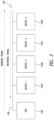
- FIG. 1 shows a block diagram of a time-domain reflectometer (TDR) 100 in accordance with an embodiment.
- the time-domain reflectometer 100 includes a processor 102 , memory 104 , a transceiver 106 , a connector 108 , a display 110 and an input device 112 .
- the processor 102 is operatively coupled to the memory 104 , transceiver 106 , display 110 and input device 112 .
- the transceiver 106 is coupled to the connector.
- the processor 102 may be any type of device that is configured to execute instructions (computer-executable instructions) that cause the processor 102 to operate as described herein.
- the processor may be a controller or a microcontroller and may include a central processing unit (CPU) or any other type of processing unit.
- the memory 104 may be any type of non-transitory computer-readable storage medium.
- the memory 104 may be read-only memory (ROM) or random access memory (RAM), among others. Further, the memory 104 may be static or dynamic.
- the memory 104 stores the computer-executable instructions that may be retrieved or accessed by the processor 102 for execution.
- the computer-executable instructions when executed by the processor 102 , cause the processor 102 (and the time-domain reflectometer 100 ) to operate as described herein.
- the transceiver 106 may be any type of device having transmitter and receiver capability and configured to transmit and receive signals over a cable. Although one transceiver 106 is shown in FIG. 1 , the time-domain reflectometer 100 may include multiple transceivers, one or more transmitters or one or more receivers. The time-domain reflectometer 100 may also include separate transmitter and receiver devices in place of the transceiver 106 . The transceiver 106 may receive a command from the processor to transmit a ranging signal for testing a cable. In response to receiving the command, the transceiver 106 may generate and output the ranging signal.
- the command which may be a trigger signal, may specify a type of the ranging signal (e.g., whether the ranging signal is a pulse or a sequence), and the transceiver 106 may generate and output the ranging signal in accordance with the command.
- a type of the ranging signal e.g., whether the ranging signal is a pulse or a sequence
- the transceiver 106 receives a reflection signal that is reflected by the cable, which may be a common bus shared by a plurality of devices.
- the reflection signal is used, as described herein, to perform ranging and find a distance along the cable between the time-domain reflectometer 100 and a device.
- the transceiver 106 outputs, to the processor 102 , data representative of the response signal.
- the connector 108 may be any type of electrical connector operative to connect the transceiver 106 to a cable (not shown).
- the connector 108 may connect to any type of cable configuration, such as a single twisted pair or multiple twisted pairs.
- the connector 108 may connect the transceiver 106 to a Telecommunications Industry Association and Electronic Industries Alliance (TIA/EIA) 485 cable (also known as a Recommended Standard (RS)-485 cable).
- TIA/EIA Telecommunications Industry Association and Electronic Industries Alliance
- RS Recommended Standard
- the display 110 may be any type of visual output device configured to output data to a user.
- the display 110 may be a screen that is configured to display a TDR trace that is generated by the processor 102 based on the response signal or a distance between the time-domain reflectometer 100 and a device.
- the input device 112 may be any type of device configured to receive user input.
- the input device 112 may be a keypad or buttons, among others.
- the input device 112 and the display 110 may be a touchscreen operative to both display data to a user and receive user input.
- a user may use the input device 112 to control the time-domain reflectometer 100 and functionality thereof.
- the time-domain reflectometer 100 may include one or more wired or wireless communication interfaces configured to communicate with an external device.
- the one or more wired or wireless communication interfaces may be a modem or transceiver.
- the one or more wired or wireless communication interfaces may communicate with the external device and may send test results to the external device.
- the processor 102 outputs a command to the transceiver 106 that instructs the transceiver 106 to transmit the ranging signal.
- the command may specify properties of the ranging signal.
- the command may specify whether the ranging signal is a pulse signal (i.e., a positive pulse or a negative pulse), a pseudorandom signal or a maximum length sequence (MLS) signal.
- the properties may include a power associated with the ranging signal and a shape or form of the ranging signal.
- the shape or form may include a step function or an impulse function.
- the properties may also include a pulse width of the ranging signal.
- the transceiver 106 After transmitting the ranging signal, the transceiver 106 receives a response signal representative of a reflection of the ranging signal. As the ranging signal traverses a cable, impedance mismatches along the cable induce reflections in the form of the response signal. The transceiver 106 receives the response signal and outputs data representative of the response signal to the processor 102 .
- the processor 102 receives the data representative of the response signal.
- the processor 102 may operate on the data representative of the response signal as described herein and generate, based on the data representative of the response signal, a TDR trace.
- the processor 102 causes the TDR trace to be displayed on the display 110 .
- the processor 102 may determine, based on the data representative of the response signal, a distance between the time-domain reflectometer 100 and a device connected to the cable.
- the processor 102 may output data representative of the distance to the display 110 or may communicate the distance information to an external system, such as a smartphone, personal computer, remote server, cloud-based computer, etc.
- the display 110 receives the data from the processor 102 and displays the TDR trace and/or the distance.
- FIG. 2 shows a testing environment for the time-domain reflectometer 100 .
- the environment includes the time-domain reflectometer 100 , a cable 120 and a plurality of devices 122 a - d (collectively referred to hereinafter by the numeral alone). Although four devices 122 (including a first device 122 a , a second device 122 b , a third device 122 c and a fourth device 122 d ) are shown, the plurality of devices 122 may include any number of devices.
- the time-domain reflectometer 100 and the plurality of devices 122 are coupled to the cable 120 . Even though the time-domain reflectometer 100 is shown to be coupled to one end of the cable 120 , the time-domain reflectometer 100 may be coupled to the cable 120 at any point along the cable 120 .
- the cable 120 is shown in FIG. 2 to have an end 124 that may be terminated or unterminated.
- the cable 120 may be an RS-485 or RS-422 cable, for example.
- the cable 120 may be in accordance with the Institute of Electrical and Electronics Engineers (IEEE) 802.3cg standard (also referred to as Single Pair Ethernet), among others.
- the cable 120 may include one twisted pair of conductors or more than one twisted pair, among other types of conductors.
- the plurality of devices 122 may be coupled to the cable 120 in a daisy-chain configuration and may take turns transmitting signals on the cable 120 (or twisted pair thereof) in a round-robin fashion.
- the plurality of devices 122 may non-simultaneously transmit signals on the twisted pair.
- the time-domain reflectometer 100 may determine a distance along the cable (or a cable length) between the time-domain reflectometer 100 and a device of the plurality of devices 122 . Personnel, such as a technician, may use the distance provided by the time-domain reflectometer 100 to locate the device, for example, in an area, a building or another type of structure or environment.
- the cable 120 may connect the devices 122 in a variety of environments including connecting building access control card readers, lighting equipment in theaters and performance venues and devices in aircraft cabins, among others.
- a device 122 connected to the cable 120 may malfunction.
- the malfunctioning device 122 may continually transmit signals over the cable 120 thereby occupying the cable 120 and preventing other devices 122 from using the cable to communicate.
- the time-domain reflectometer 100 may output a distance that usable to identify the device 122 .
- a technician may read the distance provided by time-domain reflectometer 100 and trace the distance along the cable to locate the device. Alternatively, a technician may locate the device using the distance with the aid of a blueprint.
- the cable 120 has a uniform impedance and lacks significant impedance mismatches. Accordingly, the response signal, received in response to transmitting the ranging signal, may not have significant peaks and/or valleys that are induced by an impedance mismatch.
- the device 122 when a device 122 transmits data on the cable 120 , the device 122 presents a low impedance driver on the cable 120 having an impedance that is lower than the impedance of the cable 120 or lower than the impedance of the other devices on the cable 120 .
- the device 122 presents the low impedance driver on the cable 120 not only when the device 122 is actively transmitting but also during an idle period prior to beginning active transmission and after the active transmission ends.
- the device 122 may initially present the low impedance driver on the cable at which point the device 122 may be said to be “holding the bus.” After the active transmission, the device 122 may continue to hold the bus. The device 122 may present the low impedance driver and hold the bus for a period of time that is the duration of the idle period. Before and after actively transmitting and during the idle period, neither the device 122 nor other devices 122 connected to the cable 120 may be actively transmitting.
- the time-domain reflectometer 100 may transmit the ranging signal during the idle period advantageously ensuring that the ranging signal does not interfere with transmission by the devices 122 connected to the cable 120 and vice-versa.
- the response signal when a device 122 presents low impedance on the cable 120 , the response signal has a peak (or generally a maximum or minimum) corresponding to the low impedance.
- the peak has a location (in time) corresponding to a distance between the time-domain reflectometer 100 and the device 122 .
- FIG. 3 shows a flow diagram of a method 300 for determining a distance between the time-domain reflectometer 100 and a device 122 connected to a cable 120 .
- the time-domain reflectometer 100 determines a time when to transmit a ranging signal over a cable. The time may be determined to coincide with an idle period during which the device 122 “holds the bus” but before the device 122 begins transmitting on the cable 120 or after the device 122 finishes transmitting on the cable 120 .
- the time-domain reflectometer 100 may identify the idle period based on monitoring and evaluating communications by the devices 122 that take place over the cable 120 .
- the time-domain reflectometer 100 may monitor the communications based on knowledge of the communications protocol used by the devices.
- the time-domain reflectometer 100 may monitor communications over the cable 120 and determine that an identifier (for example, an address) of the device 122 was included in the communications.
- Data transmitted by the device 122 may include an identifier of the device, for example, in a packet header.
- the presence of the identifier of the device 122 may be an indication that the device 122 is presently transmitting data and may imminently finish transmitting the data.
- the presence of the identifier of the device 122 may be an indication that the device 122 received a request to transmit data and may imminently begin transmitting data.
- the time-domain reflectometer 100 with knowledge of the communications protocol, may determine when the idle period begins and, accordingly, when to transmit the ranging signal.
- the time-domain reflectometer 100 may additionally parse the communications over the cable 120 to identify a request for transmission, a header or payload data, among others.
- the time-domain reflectometer 100 may determine the time when to transmit the ranging signal to coincide with a period of time during which the device 122 is transmitting data but the data does not transition between states. The time may coincide with a period of time during which the device 122 is transmitting a string of two or more logical zeros or two or more logical ones. When the device 122 is transmitting a string of identical bits, the device 122 may not be inputting interference on the cable 120 . Accordingly, communication over the cable 120 may be deemed to be “quiet” (in the absence of bit transitions).
- the period of time during which the device 122 is transmitting data that does not transition between states may be determined based on evaluating communications over the cable and/or properties of the communication protocol used by the device 122 communicate over the cable 120 .
- the time-domain reflectometer 100 may identify a preamble, header or payload data of a packet according to the communication protocol that includes a string of logically identical bits and a time of the string's impending transmission.
- the time-domain reflectometer 100 may transmit the ranging signal irrespective of whether the transmission coincides with the idle period or data state transitions.
- the ranging signal and the response signal may coincide or interfere with transmissions by the device 122 and vice-versa. If the ranging signal or the response signal coincides with another transmission on the cable, the ranging signal or the response signal may be corrupted and, thus, less reliable for distance determination.
- the techniques described herein may be used to improve noise and interference immunity.
- the time-domain reflectometer 100 transmits the ranging signal over the cable 120 at the determined time.
- the time-domain reflectometer 100 receives a response signal over the cable 120 at 306 .
- the response signal may have a peak (minima or maxima) associated with an impedance mismatch present on the cable resulting from the device 122 presenting a first impedance on the cable that is lower than a second impedance of the cable 120 .
- the time-domain reflectometer 100 determines, based on the response signal, a distance between the time-domain reflectometer 100 and the device 122 .
- the response signal is a time-domain signal.
- the response signal exhibits a peak corresponding to the impedance mismatch at a position of the device 122 on the cable. The position of the peak corresponds to a round-trip distance between the time-domain reflectometer 100 and the device 122 .
- the time-domain reflectometer 100 may identify the peak in the response signal and may identify the distance to the device 122 based on the speed at which the ranging signal and the response signal traverse the cable 120 and the position of the peak in the time-domain response signal.
- FIG. 4 shows a flow diagram of a method 400 for determining a distance between the time-domain reflectometer 100 and a device 122 connected to a cable 120 .
- the time-domain reflectometer 100 determines a time when the plurality of devices 122 connected to the cable 120 do not present lower impedance on the cable 120 .
- the time-domain reflectometer 100 may determine at the time based on evaluating communication or data traffic on the cable 120 . During operation, there will be periods of time when the plurality of devices 122 are not transmitting or communicating over the cable 120 . During the periods of time, the devices 122 do not present lower impedance on the cable 120 and may present high impedance on the cable 120 .
- the time-domain reflectometer 100 may determine the time based on evaluating the data trafficked over the cable. The time-domain reflectometer 100 may determine that at a present time the devices 122 are not transmitting data over the cable 120 .
- the time-domain reflectometer 100 transmits a second ranging signal at the time when the plurality of devices connected to the cable do not present a lower impedance on the cable.
- the time-domain reflectometer 100 receives a second response signal.
- the second response signal may be deemed as a baseline signal for the cable 120 or a baseline impedance for the cable 120 .
- the second response signal may be a TDR response signal that represents a natural response of the cable 120 and may represent imperfections in the cable 120 .
- the second response signal may represent a state of the cable when the devices 122 do not present a low impedance on the cable 120 .
- the second response signal may be a “baseline” for the cable 120 and may be used to calibrate and remove the effects of noise and interference from the response signal.
- the time-domain reflectometer 100 determines a distance between the time-domain reflectometer 100 and a device 122 based on the second response signal and the response signal received in response to transmitting a ranging signal at a time when the device 122 presents a low impedance on the cable.
- the time-domain reflectometer 100 may determine a difference between the response signal received in response to transmitting a ranging signal at a time when the device 122 presents a low impedance on the cable and the second response signal. By determining the difference, the time-domain reflectometer 100 removes from the response signal contributions that are due to the natural response of the cable or a structure of the cable. The contributions may be due to cable termination, nonuniformity of cable impedance, cable connections or splices, among others.
- the correlation signal is more immune to noise and interference and has a sharper peak corresponding to a device 122 presenting a low impedance on the cable 120 .
- FIG. 5 shows a flow diagram of a method 500 for determining a distance between the time-domain reflectometer 100 and a device 122 connected to a cable 120 .
- the time-domain reflectometer 100 transmits a ranging signal over the cable 120 as a sequence.
- the sequence may be a pseudo random sequence or a maximum length sequence, for example.
- the time-domain reflectometer 100 receives, over the cable, a response signal at 504 .
- the time-domain reflectometer 100 performs correlation on the response signal to produce a correlation signal at 506 .
- the time-domain reflectometer 100 may perform the correlation in accordance with Equation (1) described herein.
- the correlation signal may have a peak associated with a low impedance presented by a device 122 .
- the time-domain reflectometer 100 at 508 determines the distance between the time-domain reflectometer and the device based on the correlation signal.
- the time-domain reflectometer 100 may identify the peak and an index thereof.
- the index may represent a round-trip time between the time-domain reflectometer 100 and the device 122 .
- the round-trip time may be the time it takes the sequence to travel from the time-domain reflectometer 100 to the device 122 and for the response signal to travel from the device to the time-domain reflectometer 100 . Given that the speed of travel of the sequence and the response signal over the cable 120 are known, the distance between the time-domain reflectometer 100 and the device 122 may be determined.
- the time-domain reflectometer 100 may send a plurality of sequences over the cable 120 .
- the time-domain reflectometer 100 may average (or sum) a plurality of correlation signals corresponding to the plurality of sequences to produce an average correlation signal.
- the time-domain reflectometer 100 determines a distance based on the average (or summed) correlation signal.
- the average correlation signal improves device detection and distance determination. Individual correlation signals have stronger noise immunity than their respective response signals. Averaging the correlation signals spreads noise and interference and results in improved peak detection.
- FIG. 6 shows a flow diagram of a method 600 for determining a distance between the time-domain reflectometer 100 and a device 122 connected to a cable 120 .
- the time-domain reflectometer 100 transmits a plurality of ranging signals over the cable 120 as sequences. As described herein, each sequence may be a pseudo random sequence or a maximum length sequence.
- the time-domain reflectometer 100 receives, over the cable 120 , a plurality of response signals at 604 .
- the time-domain reflectometer 100 performs correlation on each response signal of the plurality of response signals to produce a plurality of correlation signals, respectively.
- the time-domain reflectometer 100 may perform the correlation on each response signal using Equation (1) described herein.
- the time-domain reflectometer 100 determines the distance between the time-domain reflectometer 100 and the device 122 based on the plurality of correlation signals.
- the time-domain reflectometer 100 may average the plurality of correlation signals (or take any other function of the plurality of correlation signals, such as a sum, median or mode, among others).
- the time-domain reflectometer 100 may determine the distance based on the function of the plurality of correlation signals.
- the time-domain reflectometer 100 determines a distance based on the average correlation signal. As described herein, the time-domain reflectometer 100 determines the distance by identifying a peak in the average correlation signal and determining the distance based on an index associated with the peak.
Landscapes
- Engineering & Computer Science (AREA)
- Computer Networks & Wireless Communication (AREA)
- Signal Processing (AREA)
- Physics & Mathematics (AREA)
- General Physics & Mathematics (AREA)
- Environmental & Geological Engineering (AREA)
- Radar Systems Or Details Thereof (AREA)
- Locating Faults (AREA)
Abstract
Description
c(n)=Σm r(n)r(m−n). Equation (1)
Claims (20)
Priority Applications (1)
| Application Number | Priority Date | Filing Date | Title |
|---|---|---|---|
| US17/063,250 US11575409B2 (en) | 2019-10-07 | 2020-10-05 | Time-domain reflectometer distance measurement for devices sharing a common bus |
Applications Claiming Priority (2)
| Application Number | Priority Date | Filing Date | Title |
|---|---|---|---|
| US201962911698P | 2019-10-07 | 2019-10-07 | |
| US17/063,250 US11575409B2 (en) | 2019-10-07 | 2020-10-05 | Time-domain reflectometer distance measurement for devices sharing a common bus |
Publications (2)
| Publication Number | Publication Date |
|---|---|
| US20210105043A1 US20210105043A1 (en) | 2021-04-08 |
| US11575409B2 true US11575409B2 (en) | 2023-02-07 |
Family
ID=73198429
Family Applications (1)
| Application Number | Title | Priority Date | Filing Date |
|---|---|---|---|
| US17/063,250 Active 2041-04-16 US11575409B2 (en) | 2019-10-07 | 2020-10-05 | Time-domain reflectometer distance measurement for devices sharing a common bus |
Country Status (4)
| Country | Link |
|---|---|
| US (1) | US11575409B2 (en) |
| EP (1) | EP4042579A1 (en) |
| CN (1) | CN115136556A (en) |
| WO (1) | WO2021071787A1 (en) |
Families Citing this family (1)
| Publication number | Priority date | Publication date | Assignee | Title |
|---|---|---|---|---|
| CN117113195B (en) * | 2023-09-05 | 2026-01-30 | 广东电网有限责任公司中山供电局 | A method and system for cable defect identification based on online sequence limit learning machine |
Citations (21)
| Publication number | Priority date | Publication date | Assignee | Title |
|---|---|---|---|---|
| US5751149A (en) * | 1995-12-08 | 1998-05-12 | Tempo Research Corporation | Method and apparatus for high frequency time domain reflectometry |
| US6018247A (en) | 1998-02-19 | 2000-01-25 | Kelly; John Michael | Time domain reflectometer linear position sensing |
| US6107807A (en) | 1997-06-23 | 2000-08-22 | Daimlerchrysler Ag | Method and circuit for locating a short circuit or cable break in a bus system |
| EP1193890A2 (en) | 2000-09-29 | 2002-04-03 | Siemens Aktiengesellschaft | Method and apparatus for line transmission diagnostic of a bus system |
| US20020070784A1 (en) * | 1999-11-15 | 2002-06-13 | Maynard C. Falconer | Dynamic line termination with self-adjusting impedance |
| US20020118042A1 (en) * | 2001-02-27 | 2002-08-29 | Helt Christopher G. | Circuit and method for compensation if high-frequency signal loss on a transmission line |
| US20040232919A1 (en) | 2001-06-12 | 2004-11-25 | Glenn Lacey | Fault detection system and method |
| US20040251912A1 (en) * | 2003-06-11 | 2004-12-16 | Art Pharn | Cable diagnostics using time domain reflectometry and applications using the same |
| US20050052190A1 (en) * | 2003-09-05 | 2005-03-10 | Mccosh John C. | Digital time domain reflectometer sytem |
| US20060067239A1 (en) | 2004-09-24 | 2006-03-30 | Olinski Jerome E | System and method for fault identification |
| US20100073014A1 (en) * | 2008-03-25 | 2010-03-25 | Radiodetection Ltd. | Time-Domain Reflectometer |
| US20110043244A1 (en) * | 2009-06-22 | 2011-02-24 | Utilx Corporation | On-line time domain reflectometer system |
| US7898977B2 (en) | 2002-03-01 | 2011-03-01 | Enterasys Networks Inc. | Using signal characteristics to determine the physical location of devices in a data network |
| US20110291661A1 (en) | 2010-05-25 | 2011-12-01 | Martin Stokes | Electrical fault location determination |
| US20140222356A1 (en) | 2011-09-09 | 2014-08-07 | Commissariat A L' Energie Atomique Et Aux Energies Alternatives | Temporal reflectometry system and method for unambiguously locating an electrical defect in a cable |
| US20150236643A1 (en) | 2014-02-19 | 2015-08-20 | The University Of Utah | Systems and methods for fault detection |
| US9414126B1 (en) * | 2015-03-09 | 2016-08-09 | Arcom Digital, Llc | Passive time domain reflectometer for HFC network |
| US20170104522A1 (en) * | 2015-10-12 | 2017-04-13 | Arcom Digital, Llc | Network Traffic-Compatible Time Domain Reflectometer |
| US20170176511A1 (en) | 2015-12-17 | 2017-06-22 | Bender Gmbh & Co. Kg | Method and device for extended insulation fault location in an ungrounded power supply system and method for status monitoring of the power supply system |
| US20190086466A1 (en) | 2017-09-21 | 2019-03-21 | Bender Gmbh & Co. Kg | Methods and circuit arrangements for localizing a fault location on an electric line based on time domain reflectometry |
| US20190113900A1 (en) | 2016-03-03 | 2019-04-18 | Solaredge Technologies, Ltd. | Apparatus and Method for Determining an Order of Power Devices in Power Generation Systems |
-
2020
- 2020-10-05 WO PCT/US2020/054300 patent/WO2021071787A1/en not_active Ceased
- 2020-10-05 US US17/063,250 patent/US11575409B2/en active Active
- 2020-10-05 EP EP20804013.9A patent/EP4042579A1/en active Pending
- 2020-10-05 CN CN202080069275.4A patent/CN115136556A/en active Pending
Patent Citations (21)
| Publication number | Priority date | Publication date | Assignee | Title |
|---|---|---|---|---|
| US5751149A (en) * | 1995-12-08 | 1998-05-12 | Tempo Research Corporation | Method and apparatus for high frequency time domain reflectometry |
| US6107807A (en) | 1997-06-23 | 2000-08-22 | Daimlerchrysler Ag | Method and circuit for locating a short circuit or cable break in a bus system |
| US6018247A (en) | 1998-02-19 | 2000-01-25 | Kelly; John Michael | Time domain reflectometer linear position sensing |
| US20020070784A1 (en) * | 1999-11-15 | 2002-06-13 | Maynard C. Falconer | Dynamic line termination with self-adjusting impedance |
| EP1193890A2 (en) | 2000-09-29 | 2002-04-03 | Siemens Aktiengesellschaft | Method and apparatus for line transmission diagnostic of a bus system |
| US20020118042A1 (en) * | 2001-02-27 | 2002-08-29 | Helt Christopher G. | Circuit and method for compensation if high-frequency signal loss on a transmission line |
| US20040232919A1 (en) | 2001-06-12 | 2004-11-25 | Glenn Lacey | Fault detection system and method |
| US7898977B2 (en) | 2002-03-01 | 2011-03-01 | Enterasys Networks Inc. | Using signal characteristics to determine the physical location of devices in a data network |
| US20040251912A1 (en) * | 2003-06-11 | 2004-12-16 | Art Pharn | Cable diagnostics using time domain reflectometry and applications using the same |
| US20050052190A1 (en) * | 2003-09-05 | 2005-03-10 | Mccosh John C. | Digital time domain reflectometer sytem |
| US20060067239A1 (en) | 2004-09-24 | 2006-03-30 | Olinski Jerome E | System and method for fault identification |
| US20100073014A1 (en) * | 2008-03-25 | 2010-03-25 | Radiodetection Ltd. | Time-Domain Reflectometer |
| US20110043244A1 (en) * | 2009-06-22 | 2011-02-24 | Utilx Corporation | On-line time domain reflectometer system |
| US20110291661A1 (en) | 2010-05-25 | 2011-12-01 | Martin Stokes | Electrical fault location determination |
| US20140222356A1 (en) | 2011-09-09 | 2014-08-07 | Commissariat A L' Energie Atomique Et Aux Energies Alternatives | Temporal reflectometry system and method for unambiguously locating an electrical defect in a cable |
| US20150236643A1 (en) | 2014-02-19 | 2015-08-20 | The University Of Utah | Systems and methods for fault detection |
| US9414126B1 (en) * | 2015-03-09 | 2016-08-09 | Arcom Digital, Llc | Passive time domain reflectometer for HFC network |
| US20170104522A1 (en) * | 2015-10-12 | 2017-04-13 | Arcom Digital, Llc | Network Traffic-Compatible Time Domain Reflectometer |
| US20170176511A1 (en) | 2015-12-17 | 2017-06-22 | Bender Gmbh & Co. Kg | Method and device for extended insulation fault location in an ungrounded power supply system and method for status monitoring of the power supply system |
| US20190113900A1 (en) | 2016-03-03 | 2019-04-18 | Solaredge Technologies, Ltd. | Apparatus and Method for Determining an Order of Power Devices in Power Generation Systems |
| US20190086466A1 (en) | 2017-09-21 | 2019-03-21 | Bender Gmbh & Co. Kg | Methods and circuit arrangements for localizing a fault location on an electric line based on time domain reflectometry |
Non-Patent Citations (4)
| Title |
|---|
| B&B Electronics Manufacturing Company, "RS-422 and RS-485 Application Note", Jun. 2006, 43 pages. |
| George Zimmerman et al., "IEEE P802.3cg 10 Mb/s Single Pair Ethernet: A guide", Jan. 16, 2019, 40 pages. |
| International Search Report and Written Opinion for Application No. PCT/US2020/054300, dated Dec. 18, 2020, 12 pages. |
| Thomas Kugelstadt, "The RS-485 Design Guide", Texas Instruments, Feb. 2008, 10 pages. |
Also Published As
| Publication number | Publication date |
|---|---|
| CN115136556A (en) | 2022-09-30 |
| US20210105043A1 (en) | 2021-04-08 |
| WO2021071787A1 (en) | 2021-04-15 |
| EP4042579A1 (en) | 2022-08-17 |
Similar Documents
| Publication | Publication Date | Title |
|---|---|---|
| US7906973B1 (en) | Cable tester | |
| US7808247B1 (en) | Fast cable tester | |
| AU2014218403B2 (en) | Optical fiber testing using OTDR instrument | |
| US8416699B1 (en) | Cable tester | |
| US6614236B1 (en) | Cable link integrity detector | |
| US20170201438A1 (en) | Cabling connectivity monitoring and verification | |
| US9917705B2 (en) | Device and measuring method for ascertaining the internal delay time of a can bus connection unit | |
| US20040041652A1 (en) | Equalizer, equalization method, and transmitter | |
| US8886474B2 (en) | System and apparatus for testing cable | |
| US11467993B2 (en) | Data transmission method and equipment based on single line | |
| US8472340B1 (en) | Network interface with autonegotiation and cable length measurement | |
| CN112956160B (en) | System for providing a sequence of nodes in a network | |
| EP4142222B1 (en) | Determination of a sequence of bus nodes in a multi-drop communication bus | |
| US20230318990A1 (en) | Ethernet cable open circuit checking | |
| US11575409B2 (en) | Time-domain reflectometer distance measurement for devices sharing a common bus | |
| US9664496B2 (en) | Cable length determination using variable-width pulses | |
| CN110514931B (en) | Electromagnetic compatibility test system and method for equipment with in-vehicle Ethernet function | |
| KR20210100474A (en) | Testing device of electric control unit and testing method thereof | |
| CN104283734B (en) | System and method for low cost and low-power network troubleshooting | |
| US20110313692A1 (en) | Enhanced Intelligent Patch Panel Diagnostic Management | |
| US9596139B1 (en) | Network system and method for detection and correction of duplex mismatch including duplex mode determination | |
| US20250317322A1 (en) | Controller area network wiring fault detection | |
| CN208028916U (en) | Cable Operation Monitoring System | |
| CN108833213B (en) | Ethernet link detection method and device | |
| EP4484974A1 (en) | Testing transceiver ports of a network device with on-chip time domain reflectometry diagnostic tests |
Legal Events
| Date | Code | Title | Description |
|---|---|---|---|
| FEPP | Fee payment procedure |
Free format text: ENTITY STATUS SET TO UNDISCOUNTED (ORIGINAL EVENT CODE: BIG.); ENTITY STATUS OF PATENT OWNER: LARGE ENTITY |
|
| STPP | Information on status: patent application and granting procedure in general |
Free format text: APPLICATION DISPATCHED FROM PREEXAM, NOT YET DOCKETED |
|
| STPP | Information on status: patent application and granting procedure in general |
Free format text: DOCKETED NEW CASE - READY FOR EXAMINATION |
|
| AS | Assignment |
Owner name: FLUKE CORPORATION, WASHINGTON Free format text: ASSIGNMENT OF ASSIGNORS INTEREST;ASSIGNOR:HITTEL, JOHN PAUL;REEL/FRAME:059447/0618 Effective date: 20200914 |
|
| STPP | Information on status: patent application and granting procedure in general |
Free format text: NON FINAL ACTION MAILED |
|
| STPP | Information on status: patent application and granting procedure in general |
Free format text: NOTICE OF ALLOWANCE MAILED -- APPLICATION RECEIVED IN OFFICE OF PUBLICATIONS |
|
| STPP | Information on status: patent application and granting procedure in general |
Free format text: AWAITING TC RESP., ISSUE FEE NOT PAID |
|
| STPP | Information on status: patent application and granting procedure in general |
Free format text: PUBLICATIONS -- ISSUE FEE PAYMENT RECEIVED |
|
| STPP | Information on status: patent application and granting procedure in general |
Free format text: PUBLICATIONS -- ISSUE FEE PAYMENT VERIFIED |
|
| STCF | Information on status: patent grant |
Free format text: PATENTED CASE |