US11575175B2 - Battery assembly processes - Google Patents
Battery assembly processes Download PDFInfo
- Publication number
- US11575175B2 US11575175B2 US17/191,109 US202117191109A US11575175B2 US 11575175 B2 US11575175 B2 US 11575175B2 US 202117191109 A US202117191109 A US 202117191109A US 11575175 B2 US11575175 B2 US 11575175B2
- Authority
- US
- United States
- Prior art keywords
- battery
- module
- battery module
- battery cells
- opening
- Prior art date
- Legal status (The legal status is an assumption and is not a legal conclusion. Google has not performed a legal analysis and makes no representation as to the accuracy of the status listed.)
- Active
Links
Images


Classifications
-
- H—ELECTRICITY
- H01—ELECTRIC ELEMENTS
- H01M—PROCESSES OR MEANS, e.g. BATTERIES, FOR THE DIRECT CONVERSION OF CHEMICAL ENERGY INTO ELECTRICAL ENERGY
- H01M10/00—Secondary cells; Manufacture thereof
- H01M10/04—Construction or manufacture in general
-
- H—ELECTRICITY
- H01—ELECTRIC ELEMENTS
- H01M—PROCESSES OR MEANS, e.g. BATTERIES, FOR THE DIRECT CONVERSION OF CHEMICAL ENERGY INTO ELECTRICAL ENERGY
- H01M10/00—Secondary cells; Manufacture thereof
- H01M10/42—Methods or arrangements for servicing or maintenance of secondary cells or secondary half-cells
- H01M10/425—Structural combination with electronic components, e.g. electronic circuits integrated to the outside of the casing
-
- H—ELECTRICITY
- H01—ELECTRIC ELEMENTS
- H01M—PROCESSES OR MEANS, e.g. BATTERIES, FOR THE DIRECT CONVERSION OF CHEMICAL ENERGY INTO ELECTRICAL ENERGY
- H01M50/00—Constructional details or processes of manufacture of the non-active parts of electrochemical cells other than fuel cells, e.g. hybrid cells
- H01M50/20—Mountings; Secondary casings or frames; Racks, modules or packs; Suspension devices; Shock absorbers; Transport or carrying devices; Holders
- H01M50/204—Racks, modules or packs for multiple batteries or multiple cells
- H01M50/207—Racks, modules or packs for multiple batteries or multiple cells characterised by their shape
- H01M50/213—Racks, modules or packs for multiple batteries or multiple cells characterised by their shape adapted for cells having curved cross-section, e.g. round or elliptic
-
- Y—GENERAL TAGGING OF NEW TECHNOLOGICAL DEVELOPMENTS; GENERAL TAGGING OF CROSS-SECTIONAL TECHNOLOGIES SPANNING OVER SEVERAL SECTIONS OF THE IPC; TECHNICAL SUBJECTS COVERED BY FORMER USPC CROSS-REFERENCE ART COLLECTIONS [XRACs] AND DIGESTS
- Y02—TECHNOLOGIES OR APPLICATIONS FOR MITIGATION OR ADAPTATION AGAINST CLIMATE CHANGE
- Y02E—REDUCTION OF GREENHOUSE GAS [GHG] EMISSIONS, RELATED TO ENERGY GENERATION, TRANSMISSION OR DISTRIBUTION
- Y02E60/00—Enabling technologies; Technologies with a potential or indirect contribution to GHG emissions mitigation
- Y02E60/10—Energy storage using batteries
-
- Y—GENERAL TAGGING OF NEW TECHNOLOGICAL DEVELOPMENTS; GENERAL TAGGING OF CROSS-SECTIONAL TECHNOLOGIES SPANNING OVER SEVERAL SECTIONS OF THE IPC; TECHNICAL SUBJECTS COVERED BY FORMER USPC CROSS-REFERENCE ART COLLECTIONS [XRACs] AND DIGESTS
- Y02—TECHNOLOGIES OR APPLICATIONS FOR MITIGATION OR ADAPTATION AGAINST CLIMATE CHANGE
- Y02P—CLIMATE CHANGE MITIGATION TECHNOLOGIES IN THE PRODUCTION OR PROCESSING OF GOODS
- Y02P70/00—Climate change mitigation technologies in the production process for final industrial or consumer products
- Y02P70/50—Manufacturing or production processes characterised by the final manufactured product
Definitions
- the present disclosure relates generally to manufacturing processes and, more particularly, but not by way of limitation, to process flows and methods for assembling battery modules.
- the present disclosure can be directed to a method for assembling a battery module.
- An exemplary method can include obtaining a battery module shell.
- a plurality of battery cells can be placed in the battery module shell.
- the battery cells can be electrically coupled and a control circuit can be electrically coupled to the battery cells.
- An exemplary method can include obtaining a battery module shell for containing battery cells.
- the battery module shell can have a retainer plate with rows of openings adapted to at least partially receive battery cells therein.
- the battery cells can be arranged into rows corresponding to the rows of openings in the retainer plate. At least one row of the battery cells can be robotically grasped and then placed into at least one row of openings in the retainer plate while simultaneously electrically testing each battery cell.
- the battery cells can be electrically coupled.
- a control circuit can be electrically coupled to the battery cells.
- the present disclosure can be directed to a method for assembling a battery module.
- An exemplary method can include obtaining a battery module shell for containing battery cells.
- the module shell can have a retainer plate with rows of openings adapted to at least partially receive battery cells therein.
- the battery cells can be arranged into rows corresponding to the rows of openings in the retainer plate.
- the battery cells can have an electrode end and a non-electrode end.
- At least one row of the battery cells can be robotically grasped and the following steps can be performed while continuing to grasp the battery cells: electrically testing each battery cell; placing an adhesive on the non-electrode end of each battery cell; and placing the non-electrode end of the battery cells into the openings in the retainer plate such that the adhesive contacts the retainer plate.
- the battery cells can be electrically coupled.
- a control circuit can be electrically coupled to the battery cells.
- FIG. 1 is a partial process flow diagram for assembly of battery modules according to an exemplary implementation.
- FIG. 2 is a partial process flow diagram for assembly of battery modules according to an exemplary implementation.
- FIG. 3 is a partial process flow diagram for assembly of battery modules according to an exemplary implementation.
- Inputs A and B may continue from FIGS. 1 - 2 .
- Input C may continue from FIG. 4 .
- Output D may continue to FIG. 5 .
- FIG. 4 is a partial process flow diagram for assembly of battery modules according to an exemplary implementation.
- FIG. 5 is a partial process flow diagram for assembly of battery modules according to an exemplary implementation. Output E may continue to FIG. 6 .
- FIG. 6 is a partial process flow diagram for assembly of battery modules according to an exemplary implementation.
- Input F may continue from FIG. 7 .
- Output G may continue to FIG. 8 .
- FIG. 7 is a partial process flow diagram for assembly of battery modules according to an exemplary implementation.
- FIG. 8 is a partial process flow diagram for assembly of battery modules according to an exemplary implementation. Output H may continue to FIG. 9 .
- FIG. 9 is a partial process flow diagram for assembly of battery modules according to an exemplary implementation. Output I may continue to FIG. 10 .
- FIG. 10 is a partial process flow diagram for assembly of battery modules according to an exemplary implementation.
- FIG. 11 is an exploded perspective view of an exemplary battery module.
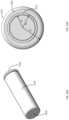
- FIG. 12 A is a perspective view of an exemplary battery cell.
- FIG. 12 B is an end view of an exemplary battery cell
- FIG. 13 is a perspective view of an exemplary module shell with a circuit board and copper bar.
- FIG. 14 is a perspective view of an exemplary module shell with an accelerator applied.
- FIG. 15 is a top view of an exemplary module shell with an accelerator and a maskant applied.
- FIG. 16 is a perspective view of an exemplary module shell and battery cells.
- FIG. 17 is a side cross-sectional view of an exemplary battery cell mounted in a bottom battery cell retainer plate.
- FIG. 18 A is a perspective view of an exemplary top battery cell retainer plate and a flexible circuit showing how they are assembled.
- FIG. 18 B is a perspective view of an exemplary assembled top battery cell retainer plate and flexible circuit.
- FIG. 19 A is a perspective view of an exemplary module shell filled with battery cells and an assembled top battery cell retainer plate and flexible circuit showing how they are assembled.
- FIG. 19 B is a top view of an exemplary assembled module shell, top battery cell retainer plate and flexible circuit.
- FIG. 20 is a perspective view of an exemplary module shell and a cover showing how they are assembled.
- FIG. 21 A is a perspective view of an exemplary assembled battery module and O-rings.
- FIG. 21 B is a perspective view of an assembled battery module with O-rings in place.
- FIG. 22 is a flow diagram of an exemplary method for assembly of a battery module.
- FIG. 23 is a flow diagram of an exemplary method for assembly of a battery module.
- FIG. 24 is a flow diagram of an exemplary method for assembly of a battery module.
- the present disclosure provides exemplary methods of assembly and manufacturing process flow for battery modules and strings of battery modules.
- Various embodiments of the process flow are described with respect to the steps illustrated in FIGS. 1 - 10 , and assembly of parts along the process flow is illustrated in FIGS. 11 - 21 B according to various embodiments.
- the battery module 1100 can comprise a module shell 1105 .
- the module shell 1105 can comprise a first opening 1145 for receiving a first plurality of battery cells 1110 therein.
- the module shell 1105 can comprise a second opening 1150 opposite the first opening 1145 for receiving a second plurality of battery cells 1110 therein.
- An inner surface of the module shell 1105 can comprise a bottom battery cell retainer plate 1175 comprising a plurality of openings to at least partially receive the battery cells 1110 therein.
- the module shell 1105 can further comprise in proximity to an outer edge of the module shell 1105 a circuit board receiving slot 1155 and a copper bar receiving slot 1160 .
- a circuit board 1115 and a copper bar 1120 can be inserted into their respective receiving slots 1155 , 1160 .
- the module shell 1105 can comprise one or more passageways 1165 extending entirely through the module shell 1105 from the first opening 1145 to the second opening 1150 to allow for wiring to pass through the battery module 1100 , for example when a plurality of battery modules 1100 are coupled together into a battery module string.
- a flex circuit 1130 can be coupled to a top battery cell retainer plate 1125 , and the resulting assembly can be coupled to the module shell 1105 across the first opening 1145 to fix the first plurality of battery cells 1110 in place.
- a cover 1135 can then be coupled to the module shell 1105 to seal the first opening 1145 .
- the cover 1135 can comprise one or more ports 1170 aligned with the passageways 1165 .
- One or more O-rings 1140 (or other sealing mechanism as known in the art) can be placed onto each of the ports 1170 .
- a cell retainer plate 1125 , a flexible circuit 1130 , and a cover 1135 can be coupled to the module shell 1105 across the second opening 1150 .
- a process flow for assembling a first half of the battery module 1100 can be initiated at step 105 , and then one or more pallets (or other handling devices) carrying containers of battery cells 1110 can be moved from a storage area to a manufacturing line at step 110 .
- Data can be captured and logged at step 120 on battery cell 1110 identification information such as manufacturer, lot number, model number, serial number, and date of manufacture. Additional data can be captured and logged at step 120 relevant to the manufacturing process such as date, time, operator name and identification number, environmental conditions (such as temperature and humidity), product for which the battery module 1100 is being built, and the like.
- the containers of battery cells 1110 can be depalletized at step 115 , and the battery cells 1110 can be removed either individually or in groups of multiple battery cells 1110 from the container at step 125 .
- the battery cells 1110 can be removed from their containers at step 125 using robotic equipment.
- the robotic equipment grasps one or more battery cells 1110 , electrical contact can be made with each battery cell 1110 so that the robotic equipment can perform quality control evaluation of the battery cells 1110 .
- the voltage and impedance of each battery cell 1110 can be checked. If the results of the quality control evaluation indicate the battery cell 1110 is within acceptable parameters, the robotic equipment can transport the battery cell 1110 to step 140 to continue the process. If the battery cell 1110 fails the quality control evaluation, then the battery cell 1110 can be rejected at step 130 . Data obtained for each quality control evaluation, for both pass and fail situations, can be logged at step 135 .
- the battery cells 1110 can be arranged in rows that correspond to the rows of openings in the bottom battery cell retainer plate 1175 .
- the robotic equipment can grasp one or more of these rows of battery cells 1110 to facilitate placement of the battery cells 1110 into the battery module shell 1105 as described in more detail below.
- each battery cell 1110 can have a mounting end 1205 and an electrical connection end 1210 opposite the mounting end 1205 as illustrated in FIG. 12 A .
- the robotic equipment can apply an adhesive 1215 to the mounting end 1205 of the battery cell 1110 as illustrated in FIG. 12 B .
- the adhesive 1215 can be paste, liquid, film pallets and tape so long as the adhesive is compatible with the submerged fluid or compatible with the base material that will be bonding to.
- the adhesive is a one part adhesive with an accelerator (LORD 202 adhesive with LORD 4 accelerator bonding nickel plated steel to plastic (PC, PCABS . . . etc.).
- the LORD 202 is an acrylic based adhesive with viscosity ranging from 8,000-32,000 cP. This adhesive bonds to unprepared metals that require little to no substrate preparation and resists dilute acids, alkalis, solvents, greases, oils and moisture, provided excellent exposure to UV exposure, salt spray and weathering.
- This adhesive is a no-mix adhesive that requires an accelerant (LORD Accelerator 4) to kick start the curing process.
- LORD Accelerator 4 an accelerant
- the adhesive can be used in a mix-in using LORD Accelerator 17, 18 & 19. The adhesive is placed on the cell or inside the one piece half shell and the accelerator placed on the cell or the one piece half shell based on the process chosen. These two methods are valid.
- the critical aspects of the adhesive is its bond line from 0.020′′-0.010′′ that gives the highest bond strength.
- the volume of the adhesive in this application case is 36 mg dispensed in a 4-12 dots with a 2.3 mm dot size.
- dots will be used to ensure that a uniform coverage of the adhesive is achieved during the bonding of cells and one piece half shells.
- the amount of accelerant is not critical as long as 0.002′′ film of accelerant is on the mating surface to activate the adhesive. Should other forms of adhesive be used, the bond line will change accordingly.
- Other adhesives can be used such as UV cure, humidity sensitive, and two part adhesives. For example, Loctite 3972, 4311 are candidates that one can consider using during the bonding process.
- the adhesive 1215 can be applied in a ring shape as illustrated in FIG. 12 B , the ring of adhesive 1215 having an outer radius of R 2 and an inner radius of R 1 .
- the volume of adhesive 1215 applied to the mounting end 1205 of the battery cell 1110 can be 2.0 mm 3 -5 mm 3 per 269.48 mm 2 surface area to satisfy design requirements and optimum coverage of the cell and to provide the strongest bond strength.
- a quality control evaluation can be performed to verify the proper placement and amount of adhesive 1215 at step 145 . If a problem is discovered with the applied adhesive 1215 , the battery cell 1110 can be moved to a rework station at step 150 . Battery cells 1110 with properly applied adhesive 1215 can proceed to step 305 (see FIG. 3 ).
- one or more pallets (or other handling devices) carrying battery module shells 1105 can be moved from a storage area to the manufacturing line at step 205 .
- the module shells 1105 can be depalletized at step 210 .
- Data can be captured and logged at step 215 on module shell 1105 identification information such as manufacturer, lot number, model number, serial number, and date of manufacture.
- a unique identification number (e.g., a serial number) can be placed onto each of the module shells 1105 at step 220 .
- the number can be printed, stamped, melted, laser etched, inscribed, or otherwise permanently affixed as is known in the art to the module shell 1105 .
- the identification number can be logged at step 225 .
- the circuit boards 1115 and the copper bars 1120 can be moved from a storage area to the manufacturing line. Either manual or robotic equipment can be used to insert the circuit boards 1115 into the circuit board receiving slot 1155 and insert the copper bar 1120 into the copper bar receiving slot 1160 of the module shell 1105 at step 235 as illustrated in FIG. 13 .
- Identification information for the circuit board 1115 can be captured at step 240 , such as manufacturer, date of manufacture, and serial number. This information can also be related to the identification information for the module shell 1105 with which the circuit board 1115 is assembled.
- the circuit board 1115 can provide a variety of functions such as monitoring of battery module 1100 performance, current draw on the battery module 1100 , condition of the battery cells 1110 , and communication between and among multiple battery modules 1100 and one or more outside intelligent agents.
- the copper bar 1120 connects one side of the battery module to the next side and combines the two side voltages into one voltage.
- the module shell 1105 with assembled circuit board 1115 and copper bar 1120 can then move to the next step of the exemplary process in which an accelerator 1405 can be applied at step 245 within each of the openings in the bottom battery cell retainer plate 1175 .
- the accelerator 1405 can be applied at minimum of 0.002′′ thick film to unlimited volume so long as there is enough coverage of the bonding surface in a ring-shaped pattern within each of the openings in the bottom battery cell retainer plate 1175 as illustrated in FIGS. 14 and 15 so that the accelerator 1405 does not cover a center portion of each opening.
- the accelerator 1405 can interact with the adhesive 1215 previously applied to the mounting end 1205 of each battery cell 1105 as described more fully below.
- the accelerator 1405 is a solvent mixture of Methylene chloride, trichloroethylene, methyl isobutyl ketone, benzoyl peroxide and methyl methacrylate. It crystalizes when sprayed on a substrate and needs to be applied to the LORD 202 in a dried state. Its viscosity is ⁇ 10 cP with density of 1.22-1.28 g/cm 3 .
- a quality control evaluation of the applied accelerator 1405 can be performed to check that the proper amount of accelerator 1405 was applied and that the accelerator 1405 was applied in the proper pattern.
- Module shells 1105 that fail the quality control evaluation can be reworked at step 255 , while module shells 1105 that pass the quality control evaluation can proceed to step 305 (see FIG. 3 ).
- FIG. 15 illustrates a top view of the module shell 1105 after application of the accelerator 1405 according to various embodiments.
- the coolant holes 1505 can allow a coolant to flow through the module shell 1105 and around the battery cells 1110 to remove excess heat that can be generated during charging or discharging of the battery cells 1110 .
- a maskant can be applied over the coolant holes 1505 to prevent stray or excess accelerator from clogging the cooling holes 1505 . The maskant can be removed prior to further processing of the module shell 1105 .
- the battery cells 1110 can be inserted as illustrated in FIG. 16 through the first opening 1145 such that the mounting end 1205 of the battery cells 1110 engage the openings of the bottom battery cell retainer plate 1175 within the module shell 1105 .
- a force can be applied to the battery cells 1110 such that the adhesive 1215 contacts the accelerator 1405 , thereby starting a chemical reaction between the adhesive 1215 and the accelerator 1405 that will hasten curing of the adhesive 1215 .
- the adhesive 1215 can begin to flow due to the applied force.
- the flowing adhesive 1215 can fill the gap between a side wall of the battery cell 1110 and the opening in the bottom battery cell retainer plate 1175 creating a bonding layer of adhesive 1215 along the mounting end 1205 of the battery cell 1110 and along the side wall of the battery cell 1110 and the opening in the bottom battery cell retainer plate 1175 .
- This continuous bonding layer can provide a strong and durable bond between the battery cell 1110 and the module shell 1105 to withstand physical shock and vibration.
- the adhesive 1215 may not flow completely across the mounting end 1205 of the battery cell 1110 as illustrated in the cross-sectional view of FIG. 17 . Having a gap in the adhesive 1215 coverage can provide better and more controlled thermal management within the battery module 1100 .
- the force can be applied for about 1-2 minutes to allow for proper flow and curing of the adhesive 1215 , although greater or lesser times are within the scope of the present disclosure depending on factors such as the type and composition of the adhesive 1215 , type and composition of the accelerator 1405 , amount of adhesive 1215 and accelerator 1405 applied, and environmental conditions such as temperature and humidity.
- one or more pallets (or other handling devices) carrying the top battery cell retainer plates 1125 can be moved from a storage area to the manufacturing line at step 405
- one or more pallets (or other handling devices) carrying the flexible circuits 1130 can be moved from a storage area to the manufacturing line at step 410 .
- the top battery cell retainer plates 1125 and the flexible circuits 1130 can be depalletized at step 415 .
- Data can be captured and logged at step 420 on the top battery cell retainer plate 1125 and the flexible circuit 1130 identification information such as manufacturer, lot number, model number, serial number, and date of manufacture.
- each of the flexible circuits 1130 can be assembled with one of the top battery cell retainer plates 1125 .
- the flexible circuit 1130 can be heat staked to the top battery cell retainer plate 1125 by ultrasonic welding, heat welding, or any other technique known in the art.
- the top battery cell retainer plate 1125 and flexible circuit 1130 can be assembled by any mechanical method known in the art.
- the top battery cell retainer plate 1125 can have a plurality of studs 1805 dispersed across a surface.
- the flexible circuit 1130 can comprise a corresponding plurality of clearance holes 1810 that align with the studs 1805 .
- the studs 1805 can protrude through the clearance holes 1810 .
- the heat staking (or other) process can melt or otherwise deform the studs 1805 , thereby coupling the flexible circuit 1130 to the top battery cell retainer plate 1125 .
- a height of the studs 1805 (e.g., stake height) can be measured to ascertain that the studs have been deformed sufficiently that they will not interfere with later attachment of the cover 1135 .
- Assemblies that fail the test can be sent for rework at step 435 , and data collected during the test can be logged at step 440 .
- Assemblies that pass the test can be processed further at step 445 where the flexible circuit 1130 can be coupled to each of the battery cells.
- the battery cell electrical connection end 1210 (opposite the end of the battery cell 1110 that received the adhesive 1215 ) can comprise a center electrode 1605 and an outer rim electrode 1610 .
- Each of the electrodes 1605 , 1610 can be coupled to the flexible circuit 1130 to complete an electric circuit.
- the center electrode 1605 can align with openings 1815 in the flexible circuit 1130
- the outer rim electrode 1610 can align with tabs 1810 located adjacent to each opening 1815 .
- the tabs 1810 can be bent inwards (towards the battery cell 1110 ) slightly to reduce or eliminate any gap between the outer rim electrode 1610 and the tab 1810 .
- the assembly of the top battery cell retainer plate 1125 and the flexible circuit 1130 can be joined in the process flow with the module shell 1105 with assembled battery cells 1110 at step 315 .
- the top battery cell retainer plate 1125 and the flexible circuit 1130 assembly can be placed on the module cell 1105 across the first opening 1145 as illustrated according to various embodiments in FIGS. 19 A and 19 B .
- An entire seam (as indicated by the arrows in FIG. 19 B ) between an outer edge of the top battery cell retainer plate 1125 and an upper edge of the module shell 1105 defining the first opening 1145 can be laser welded (or other joining method known in the art) at step 320 .
- the flexible circuit 1130 (now rigidly coupled to the module cell 1105 immediately above the electrical connection end 1210 of the battery cells 1110 ) can be welded or otherwise coupled to the electrical connection end 1210 of the battery cells 1110 .
- an optical scan can be conducted to ascertain positions of each of the battery cells 1110 relative to one or more fiducials (not shown) on the module shell 1105 to establish 2-dimensional X-Y coordinates of each battery cell 1110 .
- the Z height of each battery cell 1110 can be determined during the scan.
- the optical scan data can be compared to stored 3-dimensional CAD data to fix the position of the battery cells 1110 with the rest of the battery module 1100 structure, including the flexible circuit 1130 .
- a laser welding tab 1810 holding fixture can then be placed on top of the flexible circuit 1130 .
- the holding fixture can comprise spring-loaded fingers that can press the tabs 1810 into contact with the outer rim electrodes 1610 and the flexible circuit openings 1815 into contact with the center electrodes 1605 .
- a second optical scan can then be completed to determine the final Z height.
- the laser welder can then weld the tabs 1810 to the outer rim electrodes 1610 and the flexible circuit openings 1815 to the center electrodes 1605 .
- the laser welder can weld the copper rod 1120 to the flexible circuit 1130 . While the above description is presented in terms of laser welding, any other connection methodology known in the art can be substituted for laser welding and remain within the scope of the present disclosure. Data collected by the optical scans can be logged at step 330 .
- the module shell 1105 can be flipped at step 505 to expose the second opening 1150 .
- the process flow for assembling a second half of the battery module 1100 can be initiated at step 510 .
- the process steps for assembling the second half of the battery module 1110 are essentially the same as described above for the first half of the battery module 1100 , with the exception of the depalletizing the module shells 1105 , laser etching of the module shells 1105 , and placement of the circuit board 1115 and copper bar 1120 that occurs at steps 205 through 240 .
- steps 510 through 550 of FIG. 5 correspond to steps 110 through 150 of FIG. 1 ; steps 605 through 615 of FIG.
- steps 245 through 255 of FIG. 2 correspond to steps 245 through 255 of FIG. 2 ; steps 620 through 630 of FIG. 6 correspond to steps 305 through 315 of FIG. 3 ; steps 705 through 745 of FIG. 7 correspond to steps 405 through 445 of FIG. 4 ; and steps 805 through 815 correspond to steps 320 through 330 of FIG. 3 .
- the circuit board 1115 can be coupled to each of the flexible circuits 1130 .
- the battery module 1100 can be electrically tested at step 825 .
- the electrical test can ascertain that every battery cell 1110 is in communication with the corresponding flexible circuit 1130 , that each of the flexible circuits 1130 is in communication with the copper bar 1120 and the circuit board 1115 .
- the test can also ascertain the functionality of the circuit board 1115 such as monitoring the charge on each battery cell 1110 , voltage across the battery module 1100 , resistance across any portion of the electrical circuit of the battery module 1100 , and any desired functionality.
- Any battery modules 1100 that fail the electrical testing of step 825 can be reworked at step 830 . Data obtained during the electrical test and rework process can be logged at step 835 .
- one or more pallets (or other handling devices) carrying the covers 1135 can be moved from a storage area to the manufacturing line at step 905 .
- the covers 1135 can be depalletized at step 910 .
- Data can be captured and logged at step 915 on the cover 1135 identification information such as manufacturer, lot number, model number, serial number, and date of manufacture.
- the cover 1135 can be placed across the first opening 1145 to enclose the first half of the battery module 1100 as illustrated in FIG. 20 .
- An entire seam between an outer edge of the cover 1135 and an upper edge of the module shell 1105 defining the first opening 1145 can be laser welded (or other joining method known in the art) at step 925 .
- Step 930 Data obtained during the laser welding process can be logged at step 930 .
- the module shell 1105 can be flipped to expose the second opening 1150 .
- Steps 940 through 965 can duplicate previously described steps 905 through 925 to attach the cover 1135 across the second opening 1150 .
- one or more O-rings 1140 can be moved from a storage area to the manufacturing line at step 1005 .
- Data can be captured and logged at step 1010 on the O-ring 1140 identification information such as manufacturer, lot number, model number, serial number, and date of manufacture.
- an O-ring 1140 can be placed on each port 1170 of the covers 1135 as illustrated in FIG. 21 A according to various embodiments.
- FIG. 21 B illustrates the O-rings 1140 in place on the ports 1170 .
- the completed battery module 1100 can then be leak tested at step 1020 .
- Battery modules 1100 that fail the leak test can be reworked at step 1025 , and data collected during the leak test and rework process can be logged at step 1030 . Battery modules 1100 that pass the leak test can be moved to the next process at step 1035 .
- the actual movement can take place by a variety of mechanisms, and selection of a particular mechanism can take into account factors such as number of items being moved, weight of items being moved, distance of movement, queuing space at a work station, availability of automation, and the like.
- the movement can comprise placing items in a container and physically moving the container to the next work stations, placing the container on a manual or automated conveyor, placing the containers on a manual or automated transport vehicle, placing the items or container in position for robotic movement, and the like. Any such movement mechanism can be employed at any of the process flow steps of FIGS. 1 - 10 as deemed appropriate.
- FIG. 22 is a flowchart of an exemplary method 2200 for assembly of a battery module 1100 .
- a battery module shell 1105 can be obtained.
- a plurality of battery cells 1110 can be placed in the battery module shell 1105 at step 2210 .
- the battery cells 1110 can be electrically coupled, and a control circuit 1115 can be electrically coupled to the battery cells 1110 at step 2220 .
- FIG. 23 is a flowchart of an exemplary method 2300 for assembly of a battery module 1100 .
- a battery module shell 1105 for containing battery cells 1110 can be obtained.
- the module shell 1105 can have a retainer plate 1175 with rows of openings adapted to at least partially receive battery cells 1110 therein.
- battery cells 1110 can be arranged into rows corresponding to the rows of openings in the retainer plate 1175 .
- At least one row of the battery cells 1110 can be robotically grasped at step 2315 .
- the battery cells 1110 can be placed into at least one row of openings in the retainer plater 1175 while simultaneously electrically testing each battery cell 1110 .
- the battery cells 1110 can be electrically coupled, and a control circuit 1115 can be electrically coupled to the battery cells 1110 at step 2325 .
- FIG. 24 is a flowchart of an exemplary method 2400 for assembly of a battery module.
- a battery module shell 1105 for containing battery cells 1110 can be obtained.
- the module shell 1105 can have a retainer plate 1175 with rows of openings adapted to at least partially receive battery cells 1110 therein.
- battery cells 1110 can be arranged into rows corresponding to the rows of openings in the retainer plate 1175 .
- the battery cells 1110 can have an electrode end 1210 and a non-electrode end 1205 .
- At least one row of the battery cells 1110 can be robotically grasped at step 2415 and the following steps can be performed while continuing to grasp the battery cells 1110 : electrically testing each battery cell 1110 (step 2420 ); placing an adhesive 1215 on the non-electrode end 1205 of each battery cell 1110 (step 2425 ); and placing the non-electrode end 1205 of the battery cells 1110 into the openings in the retainer plate 1175 such that the adhesive 1215 contacts the retainer plate 1175 (step 2430 ).
- the battery cells 1110 can be electrically coupled, and a control circuit 1115 can be electrically coupled to the battery cells 1110 at step 2440 .
Landscapes
- Chemical & Material Sciences (AREA)
- Chemical Kinetics & Catalysis (AREA)
- Electrochemistry (AREA)
- General Chemical & Material Sciences (AREA)
- Engineering & Computer Science (AREA)
- Manufacturing & Machinery (AREA)
- Microelectronics & Electronic Packaging (AREA)
- Battery Mounting, Suspending (AREA)
Abstract
Description
Claims (10)
Priority Applications (1)
| Application Number | Priority Date | Filing Date | Title |
|---|---|---|---|
| US17/191,109 US11575175B2 (en) | 2016-06-22 | 2021-03-03 | Battery assembly processes |
Applications Claiming Priority (3)
| Application Number | Priority Date | Filing Date | Title |
|---|---|---|---|
| US201662353352P | 2016-06-22 | 2016-06-22 | |
| US15/630,812 US10950884B2 (en) | 2016-06-22 | 2017-06-22 | Battery assembly processes |
| US17/191,109 US11575175B2 (en) | 2016-06-22 | 2021-03-03 | Battery assembly processes |
Related Parent Applications (1)
| Application Number | Title | Priority Date | Filing Date |
|---|---|---|---|
| US15/630,812 Continuation US10950884B2 (en) | 2016-06-22 | 2017-06-22 | Battery assembly processes |
Publications (2)
| Publication Number | Publication Date |
|---|---|
| US20210194035A1 US20210194035A1 (en) | 2021-06-24 |
| US11575175B2 true US11575175B2 (en) | 2023-02-07 |
Family
ID=62064764
Family Applications (2)
| Application Number | Title | Priority Date | Filing Date |
|---|---|---|---|
| US15/630,812 Active US10950884B2 (en) | 2016-06-22 | 2017-06-22 | Battery assembly processes |
| US17/191,109 Active US11575175B2 (en) | 2016-06-22 | 2021-03-03 | Battery assembly processes |
Family Applications Before (1)
| Application Number | Title | Priority Date | Filing Date |
|---|---|---|---|
| US15/630,812 Active US10950884B2 (en) | 2016-06-22 | 2017-06-22 | Battery assembly processes |
Country Status (1)
| Country | Link |
|---|---|
| US (2) | US10950884B2 (en) |
Families Citing this family (7)
| Publication number | Priority date | Publication date | Assignee | Title |
|---|---|---|---|---|
| FR3080955B1 (en) * | 2018-05-03 | 2021-01-08 | Commissariat Energie Atomique | BATTERY ASSEMBLY PROCESS |
| US10886580B2 (en) * | 2018-08-28 | 2021-01-05 | Rivian Ip Holdings, Llc | Cylindrical battery cell packaging and cooling configuration |
| US11837706B2 (en) * | 2020-03-19 | 2023-12-05 | Rivian Ip Holdings, Llc | Adhesive bond setting with pre-cured adhesive standoffs |
| KR102660448B1 (en) | 2021-01-19 | 2024-04-23 | 주식회사 엘지에너지솔루션 | Assembly line system of stacked battery module |
| US20230253679A1 (en) * | 2022-02-07 | 2023-08-10 | GM Global Technology Operations LLC | Overmolded interconnect board assembly for power module |
| US11949080B2 (en) | 2022-09-06 | 2024-04-02 | Harbinger Motors Inc. | Battery packs with safety features and methods of installing such packs on truck frames |
| WO2024054861A1 (en) | 2022-09-06 | 2024-03-14 | Harbinger Motors Inc. | Battery modules with casted module enclosures and battery packs with safety features |
Citations (4)
| Publication number | Priority date | Publication date | Assignee | Title |
|---|---|---|---|---|
| US20100196749A1 (en) | 2008-02-29 | 2010-08-05 | Mitsubishi Heavy Industries, Ltd. | Cell container and battery |
| US20120177970A1 (en) * | 2011-01-10 | 2012-07-12 | Cobasys, Llc | Flexible battery module for prismatic cells |
| CN102646851A (en) | 2012-02-29 | 2012-08-22 | 宁波子煜自动化设备开发有限公司 | Battery core lamination machine of lithium battery |
| US20120301747A1 (en) * | 2011-05-25 | 2012-11-29 | Samsung Sdi Co., Ltd. | Battery pack |
-
2017
- 2017-06-22 US US15/630,812 patent/US10950884B2/en active Active
-
2021
- 2021-03-03 US US17/191,109 patent/US11575175B2/en active Active
Patent Citations (4)
| Publication number | Priority date | Publication date | Assignee | Title |
|---|---|---|---|---|
| US20100196749A1 (en) | 2008-02-29 | 2010-08-05 | Mitsubishi Heavy Industries, Ltd. | Cell container and battery |
| US20120177970A1 (en) * | 2011-01-10 | 2012-07-12 | Cobasys, Llc | Flexible battery module for prismatic cells |
| US20120301747A1 (en) * | 2011-05-25 | 2012-11-29 | Samsung Sdi Co., Ltd. | Battery pack |
| CN102646851A (en) | 2012-02-29 | 2012-08-22 | 宁波子煜自动化设备开发有限公司 | Battery core lamination machine of lithium battery |
Also Published As
| Publication number | Publication date |
|---|---|
| US20180131028A1 (en) | 2018-05-10 |
| US10950884B2 (en) | 2021-03-16 |
| US20210194035A1 (en) | 2021-06-24 |
Similar Documents
| Publication | Publication Date | Title |
|---|---|---|
| US11575175B2 (en) | Battery assembly processes | |
| JP7372480B2 (en) | Assembly line system for stacked battery modules | |
| TWI425899B (en) | Functional printed circuit board rapid manufacturing method and device | |
| CN105979719A (en) | Welding method for printed circuit board | |
| KR101152757B1 (en) | Secondary Battery Energy Storing Apparatus | |
| US6230963B1 (en) | Method and apparatus using colored foils for placing conductive preforms | |
| US11058013B2 (en) | Method of manufacturing battery module and interconnect board assembly with integrated PCB and flex circuit | |
| JP2007508681A (en) | Apparatus and method for interconnecting battery cells in a battery pack | |
| KR101004252B1 (en) | Battery pack manufacturing method using a battery cell moving device | |
| EP3854548B1 (en) | Electrode lead cutting apparatus for battery cells | |
| US20190173063A1 (en) | Manufacturing method of assembled battery | |
| CN105428583A (en) | Power battery grouping welding structure and power battery grouping welding method | |
| US20130045397A1 (en) | Battery pack and manufacturing method for the same | |
| US8808892B2 (en) | Temporary insulator for battery packs and associated systems and methods | |
| US20110290701A1 (en) | Workpiece carrier and workpiece carrier loading/unloading system and method | |
| CN110931449A (en) | Power module packaging structure and power module packaging method | |
| CN117691167B (en) | Battery cell module production line and battery module production line | |
| CN114682870A (en) | POP hybrid welding process and system | |
| CN101808478B (en) | Plug hole BGA screen and plug hole method of printed circuit board | |
| WO2022030633A1 (en) | Battery cell | |
| JP3225670U (en) | Joint assembly | |
| KR20150098833A (en) | Welding jig | |
| CN216700520U (en) | A local welding tool for PCB board | |
| CN224088401U (en) | Assembling device and battery production system | |
| CN117718747B (en) | Vehicle-mounted ECU assembly line and assembly method |
Legal Events
| Date | Code | Title | Description |
|---|---|---|---|
| FEPP | Fee payment procedure |
Free format text: ENTITY STATUS SET TO UNDISCOUNTED (ORIGINAL EVENT CODE: BIG.); ENTITY STATUS OF PATENT OWNER: LARGE ENTITY |
|
| STPP | Information on status: patent application and granting procedure in general |
Free format text: APPLICATION DISPATCHED FROM PREEXAM, NOT YET DOCKETED |
|
| STPP | Information on status: patent application and granting procedure in general |
Free format text: DOCKETED NEW CASE - READY FOR EXAMINATION |
|
| STPP | Information on status: patent application and granting procedure in general |
Free format text: NON FINAL ACTION MAILED |
|
| AS | Assignment |
Owner name: FARADAY&FUTURE INC., CALIFORNIA Free format text: ASSIGNMENT OF ASSIGNORS INTEREST;ASSIGNORS:OFFUTT, STEVEN HAROLD;TOROSYAN, HRAYR;SIGNING DATES FROM 20160627 TO 20160629;REEL/FRAME:059921/0412 |
|
| STPP | Information on status: patent application and granting procedure in general |
Free format text: RESPONSE TO NON-FINAL OFFICE ACTION ENTERED AND FORWARDED TO EXAMINER |
|
| STPP | Information on status: patent application and granting procedure in general |
Free format text: FINAL REJECTION MAILED |
|
| STPP | Information on status: patent application and granting procedure in general |
Free format text: RESPONSE AFTER FINAL ACTION FORWARDED TO EXAMINER |
|
| STPP | Information on status: patent application and granting procedure in general |
Free format text: AWAITING TC RESP., ISSUE FEE NOT PAID |
|
| STPP | Information on status: patent application and granting procedure in general |
Free format text: NOTICE OF ALLOWANCE MAILED -- APPLICATION RECEIVED IN OFFICE OF PUBLICATIONS |
|
| STCF | Information on status: patent grant |
Free format text: PATENTED CASE |
|
| AS | Assignment |
Owner name: SENYUN INTERNATIONAL LTD., HONG KONG Free format text: SECURITY INTEREST;ASSIGNOR:FARADAY&FUTURE, INC.;REEL/FRAME:069048/0562 Effective date: 20240925 |