US11569772B2 - Motor control device and method - Google Patents
Motor control device and method Download PDFInfo
- Publication number
- US11569772B2 US11569772B2 US17/522,905 US202117522905A US11569772B2 US 11569772 B2 US11569772 B2 US 11569772B2 US 202117522905 A US202117522905 A US 202117522905A US 11569772 B2 US11569772 B2 US 11569772B2
- Authority
- US
- United States
- Prior art keywords
- inverter
- shunt resistor
- current
- current value
- motor control
- Prior art date
- Legal status (The legal status is an assumption and is not a legal conclusion. Google has not performed a legal analysis and makes no representation as to the accuracy of the status listed.)
- Active, expires
Links
Images


Classifications
-
- H—ELECTRICITY
- H02—GENERATION; CONVERSION OR DISTRIBUTION OF ELECTRIC POWER
- H02P—CONTROL OR REGULATION OF ELECTRIC MOTORS, ELECTRIC GENERATORS OR DYNAMO-ELECTRIC CONVERTERS; CONTROLLING TRANSFORMERS, REACTORS OR CHOKE COILS
- H02P27/00—Arrangements or methods for the control of AC motors characterised by the kind of supply voltage
- H02P27/04—Arrangements or methods for the control of AC motors characterised by the kind of supply voltage using variable-frequency supply voltage, e.g. inverter or converter supply voltage
- H02P27/06—Arrangements or methods for the control of AC motors characterised by the kind of supply voltage using variable-frequency supply voltage, e.g. inverter or converter supply voltage using DC to AC converters or inverters
- H02P27/08—Arrangements or methods for the control of AC motors characterised by the kind of supply voltage using variable-frequency supply voltage, e.g. inverter or converter supply voltage using DC to AC converters or inverters with pulse width modulation
-
- H—ELECTRICITY
- H02—GENERATION; CONVERSION OR DISTRIBUTION OF ELECTRIC POWER
- H02P—CONTROL OR REGULATION OF ELECTRIC MOTORS, ELECTRIC GENERATORS OR DYNAMO-ELECTRIC CONVERTERS; CONTROLLING TRANSFORMERS, REACTORS OR CHOKE COILS
- H02P21/00—Arrangements or methods for the control of electric machines by vector control, e.g. by control of field orientation
- H02P21/14—Estimation or adaptation of machine parameters, e.g. flux, current or voltage
-
- H—ELECTRICITY
- H02—GENERATION; CONVERSION OR DISTRIBUTION OF ELECTRIC POWER
- H02P—CONTROL OR REGULATION OF ELECTRIC MOTORS, ELECTRIC GENERATORS OR DYNAMO-ELECTRIC CONVERTERS; CONTROLLING TRANSFORMERS, REACTORS OR CHOKE COILS
- H02P27/00—Arrangements or methods for the control of AC motors characterised by the kind of supply voltage
- H02P27/04—Arrangements or methods for the control of AC motors characterised by the kind of supply voltage using variable-frequency supply voltage, e.g. inverter or converter supply voltage
- H02P27/06—Arrangements or methods for the control of AC motors characterised by the kind of supply voltage using variable-frequency supply voltage, e.g. inverter or converter supply voltage using DC to AC converters or inverters
-
- G—PHYSICS
- G01—MEASURING; TESTING
- G01R—MEASURING ELECTRIC VARIABLES; MEASURING MAGNETIC VARIABLES
- G01R19/00—Arrangements for measuring currents or voltages or for indicating presence or sign thereof
- G01R19/0092—Measuring current only
-
- H—ELECTRICITY
- H02—GENERATION; CONVERSION OR DISTRIBUTION OF ELECTRIC POWER
- H02M—APPARATUS FOR CONVERSION BETWEEN AC AND AC, BETWEEN AC AND DC, OR BETWEEN DC AND DC, AND FOR USE WITH MAINS OR SIMILAR POWER SUPPLY SYSTEMS; CONVERSION OF DC OR AC INPUT POWER INTO SURGE OUTPUT POWER; CONTROL OR REGULATION THEREOF
- H02M7/00—Conversion of AC power input into DC power output; Conversion of DC power input into AC power output
- H02M7/42—Conversion of DC power input into AC power output without possibility of reversal
- H02M7/44—Conversion of DC power input into AC power output without possibility of reversal by static converters
- H02M7/48—Conversion of DC power input into AC power output without possibility of reversal by static converters using discharge tubes with control electrode or semiconductor devices with control electrode
-
- H—ELECTRICITY
- H02—GENERATION; CONVERSION OR DISTRIBUTION OF ELECTRIC POWER
- H02P—CONTROL OR REGULATION OF ELECTRIC MOTORS, ELECTRIC GENERATORS OR DYNAMO-ELECTRIC CONVERTERS; CONTROLLING TRANSFORMERS, REACTORS OR CHOKE COILS
- H02P21/00—Arrangements or methods for the control of electric machines by vector control, e.g. by control of field orientation
- H02P21/22—Current control, e.g. using a current control loop
-
- H—ELECTRICITY
- H02—GENERATION; CONVERSION OR DISTRIBUTION OF ELECTRIC POWER
- H02P—CONTROL OR REGULATION OF ELECTRIC MOTORS, ELECTRIC GENERATORS OR DYNAMO-ELECTRIC CONVERTERS; CONTROLLING TRANSFORMERS, REACTORS OR CHOKE COILS
- H02P6/00—Arrangements for controlling synchronous motors or other dynamo-electric motors using electronic commutation dependent on the rotor position; Electronic commutators therefor
- H02P6/28—Arrangements for controlling current
-
- B—PERFORMING OPERATIONS; TRANSPORTING
- B62—LAND VEHICLES FOR TRAVELLING OTHERWISE THAN ON RAILS
- B62D—MOTOR VEHICLES; TRAILERS
- B62D5/00—Power-assisted or power-driven steering
- B62D5/04—Power-assisted or power-driven steering electrical, e.g. using an electric servo-motor connected to, or forming part of, the steering gear
- B62D5/0457—Power-assisted or power-driven steering electrical, e.g. using an electric servo-motor connected to, or forming part of, the steering gear characterised by control features of the drive means as such
- B62D5/046—Controlling the motor
-
- B—PERFORMING OPERATIONS; TRANSPORTING
- B62—LAND VEHICLES FOR TRAVELLING OTHERWISE THAN ON RAILS
- B62D—MOTOR VEHICLES; TRAILERS
- B62D6/00—Arrangements for automatically controlling steering depending on driving conditions sensed and responded to, e.g. control circuits
-
- G—PHYSICS
- G01—MEASURING; TESTING
- G01R—MEASURING ELECTRIC VARIABLES; MEASURING MAGNETIC VARIABLES
- G01R1/00—Details of instruments or arrangements of the types included in groups G01R5/00 - G01R13/00 and G01R31/00
- G01R1/20—Modifications of basic electric elements for use in electric measuring instruments; Structural combinations of such elements with such instruments
- G01R1/203—Resistors used for electric measuring, e.g. decade resistors standards, resistors for comparators, series resistors, shunts
-
- G—PHYSICS
- G01—MEASURING; TESTING
- G01R—MEASURING ELECTRIC VARIABLES; MEASURING MAGNETIC VARIABLES
- G01R31/00—Arrangements for testing electric properties; Arrangements for locating electric faults; Arrangements for electrical testing characterised by what is being tested not provided for elsewhere
- G01R31/50—Testing of electric apparatus, lines, cables or components for short-circuits, continuity, leakage current or incorrect line connections
Definitions
- the present disclosure relates to motor control devices and methods, and more particularly, to a device and method of controlling a motor by measuring a current flowing through an inverter.
- embodiments of the present disclosure provide a device and method of controlling steering of a vehicle by controlling a detachable dial.
- a motor control device includes an inverter for driving a motor, a first shunt resistor connected to a first low-side switching element included in the inverter, a second shunt resistor connected to a second low-side switching element included in the inverter, a DC-link shunt resistor in series with the inverter, and a controller for controlling the inverter based on first current value measured through the first and second shunt resistors and a second current value measured through the DC-link shunt resistor.
- a motor control method includes supplying power to an inverter for driving a motor, measuring first currents flowing through a first shunt resistor connected to a first low-side switching element included in the inverter and a second shunt resistor connected to a second low-side switching element included in the inverter, measuring a second current flowing through a DC-link shunt resistor in series with the inverter, and controlling the inverter based on measured values of the first currents and a measured value of the second current.
- a motor control device and method capable of ensuring a high duty utilization rate close to a duty utilization rate in an in-line shunt resistor type by using a structure in which as two types of shunt resistors are connected, different conditions are applied to associated analog-to-digital converters (ADC).
- ADC analog-to-digital converters
- control can be maintained by measuring a corresponding current through the other type of shunt resistor.
- FIG. 1 is a block diagram of a motor control device according to aspects of the present disclosure
- FIG. 2 is a circuit diagram for explaining the motor control device according to aspects of the present disclosure
- FIG. 3 is a diagram for explaining measurement of a shunt resistor in the motor control device according to aspects of the present disclosure
- FIG. 4 is a diagram for explaining a cut-off switch included in the motor control device according to aspects of the present disclosure
- FIG. 5 illustrates a motor control method according to aspects of the present disclosure
- FIG. 6 is a diagram for more specifically explaining the step S 530 of FIG. 5 .
- first element is connected or coupled to”, “contacts or overlaps” etc. a second element
- first element is connected or coupled to” or “directly contact or overlap” the second element
- a third element can also be “interposed” between the first and second elements, or the first and second elements can “be connected or coupled to”, “contact or overlap”, etc. each other via a fourth element.
- the second element may be included in at least one of two or more elements that “are connected or coupled to”, “contact or overlap”, etc. each other.
- time relative terms such as “after,” “subsequent to,” “next,” “before,” and the like, are used to describe processes or operations of elements or configurations, or flows or steps in operating, processing, manufacturing methods, these terms may be used to describe non-consecutive or non-sequential processes or operations unless the term “directly” or “immediately” is used together.
- FIG. 1 is a block diagram of a motor control device 10 according to aspects of the present disclosure.
- the motor control device 10 may include an inverter 110 , a first shunt resistor 120 , a second shunt resistor 130 , a DC-link shunt resistor 140 , a controller 150 , and the like.
- FIG. 2 is a circuit diagram for explaining the motor control device 10 according to aspects of the present disclosure.
- the inverter 110 can drive the motor 20 .
- a three-phase motor may be used as the motor 20 .
- the inverter 110 may include a pair of switching elements corresponding to each phase. That is, the inverter 110 may include six switching elements ( 111 , 112 , 113 , 114 115 , and 116 ).
- a Metal Oxide Semiconductor Field Effect Transistor (MOSFET), an Insulated Gate Bipolar Transistor (IGBT), or the like may be used as the switching elements.
- MOSFET Metal Oxide Semiconductor Field Effect Transistor
- IGBT Insulated Gate Bipolar Transistor
- the first shunt resistor 120 may be connected to a first low-side switching element 114 included in the inverter 110 .
- the inverter 110 may include a total of six switches, that is, include two switches for each phase.
- the first shunt resistor 120 may be connected in series to any one of three phases.
- the second shunt resistor 130 may be connected to a second low-side switching element 115 included in the inverter 110 .
- the second shunt resistor 130 may be connected in series to any one of the remaining two phases except for the phase to which the first shunt resistor 120 is connected.
- first current may be current values obtained from measurements for currents flowing through the first shunt resistor 120 , the second shunt resistor 130 , and the third shunt resistor 160 , and in this case, a first current value may be obtained by adding current values flowing through the first shunt resistor 120 , the second shunt resistor 130 , and the third shunt resistor 160 .
- FIG. 3 is a diagram for explaining measurement of the shunt resistors in the motor control device according to aspects of the present disclosure.
- the motor control device 10 can measure currents of respective phase through the low-side shunt resistors.
- operational (OP) amplifiers 210 , 210 - 1 , and 210 - 2
- ADC analog-to-digital converters
- this method of measuring the currents flowing through the shunt resistors is merely one example of possible methods; thus, embodiments of the present disclosure are not limited to such a specific method as long as the currents flowing through the shunt resistors can be measured.
- a method for measuring the currents flowing through the shunt resistors may utilize typical techniques.
- a current of a phase to which any of the low-side shunt resistors is not connected can be measured by using a principle that the sum of currents flowing through three phases is zero after currents related to the phases to which the low-side shunt resistors are connected are measured.
- the currents (Iu and Iv) flowing through lines to which the first shunt resistor 120 and the second shunt resistor 130 respectively are connected that is, the current Iu flowing through the first shunt resistor 120 and the current Iv flowing through the second shunt resistor 130 can be measured first, and thereafter, the current Iw can be measured using Equation 1 below.
- I u +I v +I w 0 [Equation 1]
- the DC-link shunt resistor 130 may be connected in series to the inverter 110 .
- the motor control device 10 can measure the currents of respective phase through the DC-link shunt resistor 140 .
- a current flowing through the DC-link shunt resistor 140 can be measured by: amplifying a voltage appearing across the DC-link shunt resistor 140 using the OP amplifier 210 - 3 ; converting the amplified voltage to a digital voltage value using the ADC 220 - 3 ; and then dividing the converted digital voltage value by a resistance value of the DC-link shunt resistor 140 .
- analog-to-digital converting of the current flowing through the DC-link shunt resistor 140 may be performed in an active duty.
- a current of the remaining one phase can be calculated by substituting zero in Equation 1, which is a value corresponding to current values in respective phases, with a second current value.
- the low-side shunt resistors and the DC-link shunt resistor 140 have respective conditions related to analog-to-digital converting different from each other, it is possible to ensure a duty utilization rate of 99% close to a duty utilization rate in the in-line shunt resistor type by using this configuration including the low-side shunt resistors and the DC-link shunt resistor 140 .
- the controller 150 can control the inverter 110 based on a first current value obtained by adding the measurements for the currents flowing through the first shunt resistor 120 , the second shunt resistor 130 and third low-side switching element 116 , and a second current value obtained by measuring the current flowing through the DC-link shunt resistor.
- the controller 150 can compare the first current value with the second current value, and when the first current value matches the second current value, can control the inverter 110 . Since the first current value and the second current value are obtained only in different measurement methods in the same circuit, in general, the measured first current value and the measured second current value may be the same.
- the controller 150 can compare the first current value with the second current value, and when the first current value matches the second current value, can control the inverter 110 . In this case, the controller 150 can compare the first current value and the second current value, or compare each of the first current values for each phase and the second current value, respectively.
- the controller 150 can determine whether each part or component operates normally, and in particular, monitor whether the shunt resistors connected to the designated positions operates normally.
- the controller 150 can control the inverter 110 through any one of the first current and the second current based on a duty ratio of the circuit including the inverter 110 .
- the first shunt resistor 120 and the second shunt resistor 130 may form low-side shunt resistors, this may lead currents for each phase of the motor 20 to be measured, and thereby, a predetermined duty ratio may be present.
- the DC-link shunt resistor may also lead currents for each phase of the motor 20 to be measured, and thereby, a duty ratio different from the low-side shunt resistors may be present.
- the controller 150 may store a predetermined duty ratio in advance that is present when each shunt resistor operates alone, and compare the stored duty ratio with a duty ratio in the current state.
- a duty ratio of the circuit including these components may reach 100%, but in a situation where at least one of these components malfunctions, a resulted duty ratio may be less than 100% and represent a specific value.
- the controller 150 can compare each of a duty ratio of the low-side shunt resistors and a duty ratio of the DC-link shunt resistor with the specific value, determine that one or more of these shunt resistors matching to the specific value operate normally, and control the inverter 110 based on a current measured through the one or more shunt resistors determined as being normally operated.
- the first current or the first currents may be obtained by measuring a current flowing through the first shunt resistor 120 , a current flowing through the second shunt resistor 130 , and a current flowing through the third shunt resistor 160 .
- the controller 150 can control the inverter 110 based on the measured currents for each phase.
- the controller 150 can receive a steering command value from a steering control system (not shown) for controlling the steering of a vehicle, and transmit a control signal for controlling a power of the motor 20 to the inverter 110 to perform the steering command.
- the control signal may be a pulse width modulation (PWM) signal.
- PWM pulse width modulation
- the control signal may be transmitted to the inverter 110 through a gate driver that alternately outputs a high level signal and a low level signal at a predetermined frequency.
- FIG. 4 is a diagram for explaining a cut-off switch, such as a phase-cut-off (PCO) switch, included in the motor control device according to aspects of the present disclosure.
- PCO phase-cut-off
- the motor control device 10 may further include the cut-off switch, such as the phase-cut-off (PCO) switch, or the like, that is connected between output terminals of the inverter 110 and input terminals of the motor 20 , and is capable of transferring a driving current generated by the inverter 110 to the motor 20 or cutting off the transferring of the driving current, through on or off operations.
- the cut-off switch such as the phase-cut-off (PCO) switch, or the like, that is connected between output terminals of the inverter 110 and input terminals of the motor 20 , and is capable of transferring a driving current generated by the inverter 110 to the motor 20 or cutting off the transferring of the driving current, through on or off operations.
- PCO phase-cut-off
- the PCO switch can operate in any one of on and off states, and when the PCO switch operates in the on state, transfer the driving current from the inverter 110 to the motor 20 . Further, when the PCO switch operates in the off state, the PCO switch can cut off the transferring of the driving current from the inverter 110 to the motor 20 .
- the PCO switch can cut off the driving current when the controller 150 abnormally operates. Specifically, in a situation where the controller 150 normally operates, the PCO switch can operate in the on state, and transfer the driving current from the inverter 110 to the motor 20 . Further, in a situation where the controller 150 abnormally operates, the PCO switch can operate in the off state, and cut off the transferring of the driving current from the inverter 110 to the motor 20 . For example, when the inverter 110 is short-circuited, and an overcurrent is provided as the driving current, the PCO switch can cut off the transferring of the driving current to the motor 20 .
- a micro controller unit may be implemented as the controller 150 .
- the micro controller unit (MCU) may include at least one or more of one or more processors, memories, storage, user interface for inputting and user interface for outputting, which communicate with one another via buses. Further, the micro controller unit (MCU) may also include a network interface to access networks.
- the processor may be a CPU or a semiconductor element or device capable of executing processing instructions stored in memory and/or storage.
- the memory and the storage may include various types of volatile/non-volatile storage media. For example, the memory may include ROM and RAM.
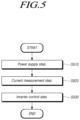
- FIG. 5 is a flow diagram illustrating the motor control method according to aspects of the present disclosure.
- the motor control method may include a power supply step in which power is supplied to an inverter 110 for driving a motor 20 , at step S 510 , a current measurement step in which first currents flowing through a first shunt resistor 120 connected to a first low-side switching element 114 and a second shunt resistor 130 connected to a second low-side switching element 115 included in the inverter 110 are measured, and a second current flowing through a DC-link shunt resistor in series with the inverter 110 is measured, at step S 520 , and an inverter control step in which the inverter 110 is controlled based on measured values of the first currents and a measured value of the second current, at step S 530 .
- FIG. 6 is a diagram for more specifically explaining the step S 530 of FIG. 5 .
- the motor control device 10 can measure the first currents, at step S 610 . Specifically, the motor control device 10 can further measure a current flowing through a third shunt resistor 160 connected to a third low-side switching element 116 of the inverter 110 .
- the current measured through the third shunt resistor 160 may be included in the first currents.
- a first current value can be obtained by adding current flowing through the first shunt resistor 120 , current flowing through the second shunt resistor 130 and current flowing through the third shunt resistor 160 .
- the motor control device 10 can measure a second current flowing through the DC-link shunt resistor 140 connected in series with the inverter 110 , and obtain a second current value, at step S 620 .
- the motor control device 10 can determine whether the first current value and the second current value match to each other, at step S 630 .
- the motor control device 10 can control the inverter 110 based on the first current value, or the second current, at step S 640 .
- the motor control device 10 can determine whether one or more of the shunt resistors abnormally operate based on a duty ratio, at step S 650 .
- the duty ratio may mean a conduction ratio of a circuit including the inverter 110 , that is, a power supply for supplying power to the inverter 110 and a circuit including the motor 20 driven by the inverter 110 . Further, it is possible to determine whether one or more of the shunt resistors abnormally operate based on a predetermined duty ratio maintained by the low-side shunt resistors and a duty ratio of another value maintained by the DC-link shunt resistor 140 .
- a corresponding duty ratio may be higher than the previous two duty ratios. Therefore, in the case of the highest duty ratio, all of the shunt resistors are normal, and it is possible to determine whether each of the shunt resistors is normal through a predetermined duty ratio that is present when the low-side shunt resistors are normal and a duty ratio of another value that is present when the DC-link shunt resistor 140 is normal.
- the motor control device and method capable of ensuring a high duty utilization rate close to a duty utilization rate in the in-line shunt resistor type by using the structure in which as two types of shunt resistors are connected, different conditions are applied to associated analog-to-digital converters (ADC).
- ADC analog-to-digital converters
- control can be maintained by measuring a corresponding current through the other type of shunt resistor.
Landscapes
- Engineering & Computer Science (AREA)
- Power Engineering (AREA)
- Physics & Mathematics (AREA)
- General Physics & Mathematics (AREA)
- Inverter Devices (AREA)
- Control Of Ac Motors In General (AREA)
Abstract
Description
I u +I v +I w=0 [Equation 1]
Claims (13)
Applications Claiming Priority (2)
| Application Number | Priority Date | Filing Date | Title |
|---|---|---|---|
| KR10-2020-0150129 | 2020-11-11 | ||
| KR1020200150129A KR102864308B1 (en) | 2020-11-11 | 2020-11-11 | Motor control apparatus and method |
Publications (2)
| Publication Number | Publication Date |
|---|---|
| US20220149766A1 US20220149766A1 (en) | 2022-05-12 |
| US11569772B2 true US11569772B2 (en) | 2023-01-31 |
Family
ID=81256212
Family Applications (1)
| Application Number | Title | Priority Date | Filing Date |
|---|---|---|---|
| US17/522,905 Active 2041-11-10 US11569772B2 (en) | 2020-11-11 | 2021-11-10 | Motor control device and method |
Country Status (4)
| Country | Link |
|---|---|
| US (1) | US11569772B2 (en) |
| KR (1) | KR102864308B1 (en) |
| CN (1) | CN114553105B (en) |
| DE (1) | DE102021212704A1 (en) |
Families Citing this family (7)
| Publication number | Priority date | Publication date | Assignee | Title |
|---|---|---|---|---|
| JP7501355B2 (en) * | 2020-12-28 | 2024-06-18 | ニデック株式会社 | MOTOR CONTROL DEVICE, MOTOR, MOTOR CONTROL METHOD, AND PROGRAM |
| EP4306970A1 (en) | 2022-07-13 | 2024-01-17 | Siemens Aktiengesellschaft | Device and method for inspection and / or monitoring of a phase |
| DE102022117708A1 (en) * | 2022-07-15 | 2024-01-18 | Miele & Cie. Kg | Drive system |
| US12476566B2 (en) | 2023-04-19 | 2025-11-18 | Hl Mando Corporation | Electronic control device using shunt resistor and current detection circuit |
| EP4482019A1 (en) * | 2023-06-19 | 2024-12-25 | E.G.O. Elektro-Gerätebau GmbH | Method and device for driving a three-phase motor with three-phase current |
| KR102821241B1 (en) * | 2023-07-04 | 2025-06-18 | 계양전기 주식회사 | Device for controlling motor of power tool |
| KR20250048931A (en) | 2023-10-04 | 2025-04-11 | 주식회사 모티 | Apparatus and method of controlling operation of regenerative circuit in motor driving system |
Citations (5)
| Publication number | Priority date | Publication date | Assignee | Title |
|---|---|---|---|---|
| US20120163046A1 (en) * | 2009-09-28 | 2012-06-28 | Hiroshi Hibino | Phase current detection device and power conversion device using the same |
| US20150214882A1 (en) * | 2014-01-28 | 2015-07-30 | Denso Corporation | Power conversion device and electric power steering device using the same |
| US20170070172A1 (en) * | 2015-07-10 | 2017-03-09 | Lg Electronics Inc. | Motor driving apparatus and home appliance including the same |
| US20170201201A1 (en) * | 2016-01-07 | 2017-07-13 | Denso Corporation | Current detection apparatus and control apparatus of rotary electric machine |
| US20180342970A1 (en) * | 2017-05-25 | 2018-11-29 | Hyundai Mobis Co., Ltd. | System and method for controlling motor |
Family Cites Families (4)
| Publication number | Priority date | Publication date | Assignee | Title |
|---|---|---|---|---|
| JP5057908B2 (en) * | 2007-09-13 | 2012-10-24 | オムロンオートモーティブエレクトロニクス株式会社 | Multi-phase AC motor drive device |
| KR20140052138A (en) * | 2012-10-19 | 2014-05-07 | 학교법인 두원학원 | Invertor device for electric motor comprising shunt resistance for detecting current |
| KR20170067934A (en) * | 2015-12-08 | 2017-06-19 | 현대자동차주식회사 | Device for controlling motor |
| CN110168920A (en) * | 2017-01-31 | 2019-08-23 | 日本电产株式会社 | Motor drive and electric power steering apparatus |
-
2020
- 2020-11-11 KR KR1020200150129A patent/KR102864308B1/en active Active
-
2021
- 2021-11-10 US US17/522,905 patent/US11569772B2/en active Active
- 2021-11-11 CN CN202111332981.6A patent/CN114553105B/en active Active
- 2021-11-11 DE DE102021212704.5A patent/DE102021212704A1/en active Pending
Patent Citations (5)
| Publication number | Priority date | Publication date | Assignee | Title |
|---|---|---|---|---|
| US20120163046A1 (en) * | 2009-09-28 | 2012-06-28 | Hiroshi Hibino | Phase current detection device and power conversion device using the same |
| US20150214882A1 (en) * | 2014-01-28 | 2015-07-30 | Denso Corporation | Power conversion device and electric power steering device using the same |
| US20170070172A1 (en) * | 2015-07-10 | 2017-03-09 | Lg Electronics Inc. | Motor driving apparatus and home appliance including the same |
| US20170201201A1 (en) * | 2016-01-07 | 2017-07-13 | Denso Corporation | Current detection apparatus and control apparatus of rotary electric machine |
| US20180342970A1 (en) * | 2017-05-25 | 2018-11-29 | Hyundai Mobis Co., Ltd. | System and method for controlling motor |
Also Published As
| Publication number | Publication date |
|---|---|
| US20220149766A1 (en) | 2022-05-12 |
| DE102021212704A1 (en) | 2022-05-12 |
| CN114553105A (en) | 2022-05-27 |
| KR20220064050A (en) | 2022-05-18 |
| CN114553105B (en) | 2026-03-24 |
| KR102864308B1 (en) | 2025-09-25 |
Similar Documents
| Publication | Publication Date | Title |
|---|---|---|
| US11569772B2 (en) | Motor control device and method | |
| US6788088B2 (en) | Semiconductor device equipped with current detection function | |
| US6377034B1 (en) | Method and circuits for inductor current measurement in MOS switching regulators | |
| KR102294347B1 (en) | Junction Temperature and Current Sensing Techniques | |
| US11675011B2 (en) | Switch condition monitoring | |
| JP2015519035A (en) | Method and controller for an electric motor with fault detection | |
| US20250175171A1 (en) | Switch Module Having a Short Circuit Detection Circuit | |
| US10658947B2 (en) | Semiconductor device, power module, and control method of power conversion device | |
| US10585131B2 (en) | In-vehicle determination circuit and in-vehicle power supply device | |
| JP3575166B2 (en) | Current detector | |
| US20160276940A1 (en) | Power conversion circuit system | |
| US7208925B2 (en) | Voltage regulator controller power good indicator circuitry | |
| US20230009865A1 (en) | Power supply control apparatus and semiconductor failure detection method | |
| CN110557115A (en) | Gate interface circuit | |
| US11152934B2 (en) | Device and method for controlling switching | |
| CN107223296B (en) | Method and apparatus for determining load current | |
| CN102656473A (en) | Method and apparatus for calibrating voltage measuring devices on drive circuits | |
| WO2015092522A1 (en) | Drive control apparatus for semiconductor device | |
| US12044705B2 (en) | Device for measuring current of three-phase inverter and method therefor | |
| JP2023106341A (en) | Method and apparatus for reducing voltage load on semiconductor devices of inverter | |
| US8547714B2 (en) | Output inverter for single phase and output current detecting method thereof | |
| JP2018148635A (en) | Inverter overcurrent detection circuit | |
| JPWO2022249284A5 (en) | ||
| CN113098363A (en) | Control apparatus and control method | |
| JP4517901B2 (en) | Power semiconductor module and drive circuit thereof |
Legal Events
| Date | Code | Title | Description |
|---|---|---|---|
| FEPP | Fee payment procedure |
Free format text: ENTITY STATUS SET TO UNDISCOUNTED (ORIGINAL EVENT CODE: BIG.); ENTITY STATUS OF PATENT OWNER: LARGE ENTITY |
|
| STPP | Information on status: patent application and granting procedure in general |
Free format text: DOCKETED NEW CASE - READY FOR EXAMINATION |
|
| STPP | Information on status: patent application and granting procedure in general |
Free format text: NON FINAL ACTION MAILED |
|
| STPP | Information on status: patent application and granting procedure in general |
Free format text: RESPONSE TO NON-FINAL OFFICE ACTION ENTERED AND FORWARDED TO EXAMINER |
|
| STPP | Information on status: patent application and granting procedure in general |
Free format text: NOTICE OF ALLOWANCE MAILED -- APPLICATION RECEIVED IN OFFICE OF PUBLICATIONS |
|
| AS | Assignment |
Owner name: HL MANDO CORPORATION, KOREA, REPUBLIC OF Free format text: CHANGE OF NAME;ASSIGNOR:MANDO CORPORATION;REEL/FRAME:062152/0127 Effective date: 20220905 |
|
| AS | Assignment |
Owner name: MANDO CORPORATION, KOREA, REPUBLIC OF Free format text: ASSIGNMENT OF ASSIGNORS INTEREST;ASSIGNOR:PARK, JAE SANG;REEL/FRAME:062217/0451 Effective date: 20211103 |
|
| STPP | Information on status: patent application and granting procedure in general |
Free format text: PUBLICATIONS -- ISSUE FEE PAYMENT VERIFIED |
|
| STCF | Information on status: patent grant |
Free format text: PATENTED CASE |