US11567321B2 - Distortion calibration glasses, distortion correction head-up display device and system, image display distortion correction method and in-vehicle system - Google Patents
Distortion calibration glasses, distortion correction head-up display device and system, image display distortion correction method and in-vehicle system Download PDFInfo
- Publication number
- US11567321B2 US11567321B2 US16/295,136 US201916295136A US11567321B2 US 11567321 B2 US11567321 B2 US 11567321B2 US 201916295136 A US201916295136 A US 201916295136A US 11567321 B2 US11567321 B2 US 11567321B2
- Authority
- US
- United States
- Prior art keywords
- distortion
- image
- correction
- standard plate
- head
- Prior art date
- Legal status (The legal status is an assumption and is not a legal conclusion. Google has not performed a legal analysis and makes no representation as to the accuracy of the status listed.)
- Active, expires
Links
Images


Classifications
-
- G—PHYSICS
- G02—OPTICS
- G02B—OPTICAL ELEMENTS, SYSTEMS OR APPARATUS
- G02B27/00—Optical systems or apparatus not provided for by any of the groups G02B1/00 - G02B26/00, G02B30/00
- G02B27/0025—Optical systems or apparatus not provided for by any of the groups G02B1/00 - G02B26/00, G02B30/00 for optical correction, e.g. distorsion, aberration
-
- G—PHYSICS
- G02—OPTICS
- G02B—OPTICAL ELEMENTS, SYSTEMS OR APPARATUS
- G02B27/00—Optical systems or apparatus not provided for by any of the groups G02B1/00 - G02B26/00, G02B30/00
- G02B27/01—Head-up displays
- G02B27/017—Head mounted
- G02B27/0172—Head mounted characterised by optical features
-
- B—PERFORMING OPERATIONS; TRANSPORTING
- B60—VEHICLES IN GENERAL
- B60R—VEHICLES, VEHICLE FITTINGS, OR VEHICLE PARTS, NOT OTHERWISE PROVIDED FOR
- B60R11/00—Arrangements for holding or mounting articles, not otherwise provided for
- B60R11/02—Arrangements for holding or mounting articles, not otherwise provided for for radio sets, television sets, telephones, or the like; Arrangement of controls thereof
- B60R11/0229—Arrangements for holding or mounting articles, not otherwise provided for for radio sets, television sets, telephones, or the like; Arrangement of controls thereof for displays, e.g. cathodic tubes
-
- G—PHYSICS
- G02—OPTICS
- G02B—OPTICAL ELEMENTS, SYSTEMS OR APPARATUS
- G02B5/00—Optical elements other than lenses
- G02B5/30—Polarising elements
- G02B5/3025—Polarisers, i.e. arrangements capable of producing a definite output polarisation state from an unpolarised input state
-
- G06T5/006—
-
- G—PHYSICS
- G06—COMPUTING OR CALCULATING; COUNTING
- G06T—IMAGE DATA PROCESSING OR GENERATION, IN GENERAL
- G06T5/00—Image enhancement or restoration
- G06T5/80—Geometric correction
-
- B—PERFORMING OPERATIONS; TRANSPORTING
- B60—VEHICLES IN GENERAL
- B60R—VEHICLES, VEHICLE FITTINGS, OR VEHICLE PARTS, NOT OTHERWISE PROVIDED FOR
- B60R2300/00—Details of viewing arrangements using cameras and displays, specially adapted for use in a vehicle
- B60R2300/20—Details of viewing arrangements using cameras and displays, specially adapted for use in a vehicle characterised by the type of display used
- B60R2300/205—Details of viewing arrangements using cameras and displays, specially adapted for use in a vehicle characterised by the type of display used using a head-up display
-
- G—PHYSICS
- G02—OPTICS
- G02B—OPTICAL ELEMENTS, SYSTEMS OR APPARATUS
- G02B27/00—Optical systems or apparatus not provided for by any of the groups G02B1/00 - G02B26/00, G02B30/00
- G02B27/01—Head-up displays
- G02B27/0101—Head-up displays characterised by optical features
- G02B2027/011—Head-up displays characterised by optical features comprising device for correcting geometrical aberrations, distortion
-
- G—PHYSICS
- G02—OPTICS
- G02B—OPTICAL ELEMENTS, SYSTEMS OR APPARATUS
- G02B27/00—Optical systems or apparatus not provided for by any of the groups G02B1/00 - G02B26/00, G02B30/00
- G02B27/01—Head-up displays
- G02B27/0101—Head-up displays characterised by optical features
- G02B2027/0112—Head-up displays characterised by optical features comprising device for genereting colour display
- G02B2027/0114—Head-up displays characterised by optical features comprising device for genereting colour display comprising dichroic elements
-
- G—PHYSICS
- G02—OPTICS
- G02B—OPTICAL ELEMENTS, SYSTEMS OR APPARATUS
- G02B27/00—Optical systems or apparatus not provided for by any of the groups G02B1/00 - G02B26/00, G02B30/00
- G02B27/01—Head-up displays
- G02B27/0101—Head-up displays characterised by optical features
- G02B2027/014—Head-up displays characterised by optical features comprising information/image processing systems
-
- G—PHYSICS
- G02—OPTICS
- G02B—OPTICAL ELEMENTS, SYSTEMS OR APPARATUS
- G02B27/00—Optical systems or apparatus not provided for by any of the groups G02B1/00 - G02B26/00, G02B30/00
- G02B27/01—Head-up displays
- G02B27/017—Head mounted
- G02B2027/0178—Eyeglass type
Definitions
- the present disclosure relates to the field of in-vehicle electronic devices, and more specifically to distortion calibration glasses, a distortion correction head-up display device, and system, an image display distortion correction method, and an in-vehicle system.
- Head-Up Displays result in an image distortion due to optical systems and windshields being off-axis. This distortion can be corrected statically by an image source before leaving the factory. However, when a driver's head movement during actual driving cause eyeglass position to change, projection distortion can also change, causing the distortion compensation set at the factory to sometimes be inappropriate. In addition, due to the windshield manufacturing and installation accuracy error and in-vehicle system vibration, the HUD internal optical component position error can also introduce the distortion which needs to be corrected in a timely fashion.
- a human eye distortion calibration glasses for a head-up display device including: a first lens, a second lens and a correction structure, where
- the first distortion degree is determined based on an original image and the first distortion image of the first standard plate
- the second distortion degree is determined based on an original image and the second distortion image of the second standard plate.
- the calibration structure is configured to enable the first correction image and the second correction image to transmit alternately to left and right eyes of a user at a predetermined time interval.
- the human eye distortion calibration glasses further includes a first dichroic mirror corresponding to the first standard plate and a second dichroic mirror corresponding to the second standard plate;
- original images of the first standard plate and the second standard plate each includes square structures arranged in an array.
- a distortion correction head-up display device including an image generation circuit, an optical path circuit, and a control circuit, where
- the third polarizer is configured to adjust the polarization direction to the first polarization direction and the second polarization direction alternately at a first predetermined time interval, to generate the first correction image and the second correction image alternately at the first predetermined time interval.
- the distortion correction head-up display device further includes an image acquisition circuit configured to acquire distortion images of original images and output the distortion images to the control circuit, to enable the first and the second distortion calibration signal to have distortion degrees relative to the original images.
- the first distortion degree is determined based on an original image and a first distortion image of a first standard plate
- the second distortion degree is determined based on an original image and a second distortion image of a second standard plate.
- the image generation circuit is further configured to generate calibration signal light, or the device further includes a light source configured to emit calibration signal light;
- the calibration signal light and the first correction image are alternately generated at a second predetermined time interval, or the calibration signal light and the second correction image are alternately generated at the second predetermined time interval.
- the optical path circuit further includes a third dichroic mirror configured to reflect images reflected by the first and the second standard plates to an image acquisition circuit, where the images pass through the optical path circuit and form distortion images.
- a third dichroic mirror configured to reflect images reflected by the first and the second standard plates to an image acquisition circuit, where the images pass through the optical path circuit and form distortion images.
- a distortion correction head-up display system including a head-up display device and a distortion calibration glasses, where the distortion calibration glasses includes a first lens, a second lens and a correction structure, where
- the third polarizer is configured to adjust the polarization direction to the first polarization direction and the second polarization direction alternately at a first predetermined time interval, to generate the first correction image and the second correction image alternately at the first predetermined time interval.
- the correction structure includes a first standard plate corresponding to the first lens and a second standard plate corresponding to the second lens;
- the calibration signal light and the first correction image or the second correction image are generated alternately at a second predetermined time interval; and/or
- An image display distortion correction method applying the distortion correction head-up display system hereinabove is further provided in the present disclosure, including:
- the distortion correction head-up display device further includes an image acquisition circuit, where
- a vehicle-mounted system including the distortion correction head-up display system hereinabove is further provided.
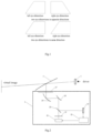
- FIG. 1 is a schematic view of a distortion principle in some embodiments of the present disclosure.
- FIG. 2 is a schematic view of a distortion correction head-up display device in some embodiments of the present disclosure.
- FIG. 3 is a schematic view of a distortion correction head-up display device in some embodiments of the present disclosure.
- FIG. 4 is a schematic view of a distortion calibration glasses in some embodiments of the present disclosure.
- FIG. 5 is a schematic view of a distortion calibration glasses in some embodiments of the present disclosure.
- FIG. 6 is a flow chart of a distortion correction method in some embodiments of the present disclosure.
- FIG. 7 is a schematic view of original images of a first standard plate and a second standard plate in some embodiments of the present disclosure.
- the image correction technique for the heads-up display is to correct the entire image, so the left and right eyes cannot be distinguished, resulting in that the correction is only effective for one of the eyes, while the other eye may be subjected to a distortion accumulation, so the correction effect is poor.
- FIG. 1 since the left and right eyes are located at different positions relative to the window, the distortions of the left and right eyes are different. When the distortions of the two eyes are in the same direction, if the distortion of any eye is corrected, and the distortion of the other eye is also reduced. When the distortions of the two eyes are in opposite directions, when the distortion of one eye is corrected, the distortion of the other eye may be increased.
- the present disclosure improves the head-up display device and the glasses matched thereto, and the present disclosure will be described in detail below with reference to FIGS. 2 - 5 .
- FIG. 2 is a schematic view of a distortion correction head-up display device in some embodiments of the present disclosure.
- the distortion correction head-up display device includes a head-up display device 2 and a glasses 1 .
- the correction image generated by the head-up display device 2 passes through the windshield and passes through the glass cover 27 of the device, and then the correction image is reflected by the windshield 3 outside the device to the user or the driver's eye, so that the driver may see the image projected onto the windshield 3 .
- the image passes the glass cover 27 and the windshield 3 , so the optical path thereof may cause distortions of different degrees for the left and right eyes respectively.
- the glasses 1 includes a first lens corresponding to a user or a driver's left eye, a second lens corresponding to a user or a driver's right eye, and a correction structure disposed on the glasses 1 .
- the correction structure includes a first polarizer 121 having a first polarization direction corresponding to the first lens and a second polarizer 122 having a second polarization direction corresponding to the second lens.
- the polarization direction of the first polarizer 121 may be perpendicular to the first lens, and a polarization direction of the second polarizer 122 may be parallel to the second lens, the disclosure is not limited thereto, and the polarization directions may be other directions as long as the polarization direction of the first polarizer 121 is perpendicular to that of the second polarizer 122 , so that when one of the eyes (for example, the left eye) receives the correction image (first correction image), the other eye (right eye) is completely shielded from receiving the correction image (first correction image), so as to avoid mutual interference and vice versa.
- the polarization direction of the polarizer can be adjusted by rotating the polarizer, the detailed description thereof is omitted herein.
- the image generated by the head-up display device 2 may only pass through one polarizer, and the head-up display device 2 may generate two different correction images respectively for the left and right eyes in a time-sharing manner.
- the first correction image has a vibration direction as same as the polarization direction of the first polarizer 121 .
- the vibration direction of the first image may be perpendicular to a vibration direction of the first lens.
- the head-up display device 2 When the head-up display device 2 outputs the first correction image, sine the polarization direction of the second polarizer 122 is perpendicular to the vibration direction of the first correction image, so the first correction image is shielded by the second polarizer 122 , the right eye cannot acquire the first correction image. On the contrary, the left eye cannot acquire the second correction image.
- the output image of the head-up display device 2 is alternately switched by means of time division multiplexing.
- the head-up display device 2 includes: an image generation circuit 21 , an optical path circuit and a control circuit 22 .
- the control circuit 22 is configured to generate a first distortion calibration signal and a second distortion calibration signal respectively based on a first distortion degree and a second distortion degree which are predetermined.
- the predetermined distortion degree may be a pre-stored distortion degree, including a first distortion degree adjusted to the system for the left eye and a second distortion degree adjusted to the system for the right eye.
- the first distortion degree and the second distortion degree may be fixed values, or may be switched to a plurality of variable values by a predetermined trigger condition. For example, when the trigger condition is that the user or the driver adjusts the seat to a certain extent, the switch is performed, and at this time, the system has a plurality of built in different assignments, and corresponds the assignments to specific scenario, thereby being able to adapt to different scenarios.
- the image generation circuit 21 is configured to receive the first distortion calibration signal and generate a first correction image subjected to a distortion correction and receive the second distortion calibration signal and generate a second correction image subjected to a distortion correction.
- the optical path circuit includes an adjustable third polarizer 25 .
- the third polarizer is configured to adjust the polarization direction to be, for example, a polarization direction perpendicular to the first lens or a direction polarization parallel to the second lens based on a predetermined condition, so that the head-up display device 2 may output the first correction image of which the vibration direction is the same as the polarization direction of the first polarizer and the second correction image of which the vibration direction is the same as the polarization direction of the second polarizer image.
- the two correction images can be entered into the corresponding eyes respectively in a time-division manner, so the generated correction images may not be affected by each other.
- the distortion degree is obtained by a preprocessing.
- the distortion degree acquired by the preprocessing is different from the predetermined distortion degree, which may be the distortion degree acquired in real time according to a specific scenario.
- the algorithm involved and the scene processing is more complicated, which generally requires a more complicated processor for calculation processing.
- the correction structure further includes a first standard plate 111 corresponding to the first lens and a second standard plate 112 corresponding to the second lens.
- FIG. 7 is a schematic view of original images of a first standard plate and a second standard plate.
- the image generation circuit 21 is configured to transmit the calibration signal light to the first standard plate 111 and the second standard plate 112 , to obtain a first distortion image of the first standard plate 111 and a second distortion image of the second standard plate 112 .
- the control circuit 22 is configured to generate the first distortion calibration signal based on the first distortion image and the original image of the first standard plate 111 and generate the second distortion calibration signal based on the second distortion image and the original image of the second standard plate 112 .
- the image generation circuit 21 is configured to generate the first correction image and second correction image respectively based on the first distortion calibration signal and the second distortion calibration signal.
- the light source 28 includes a point source 281 , a beam expander 282 and a micro lens array 283 for generating calibration signal light, such as a near-infrared source.
- the original image of the first standard plate 111 and the original image of the second standard plate 112 may be the same or different.
- the original image of the first standard plate 111 and the original image of the second standard plate 112 are the same, so as to avoid lowering distortion correction accuracy.
- original images of the first standard plate and the second standard plate each includes square structures arranged in an array.
- the head-up display device 2 further includes an image acquisition circuit 23 , such as a camera or the like, configured to acquire distortion images of the first standard plate and the second standard plate.
- an image acquisition circuit 23 such as a camera or the like, configured to acquire distortion images of the first standard plate and the second standard plate.
- the original images of the first standard plate and the second standard plate may be pre-stored in the storage medium in the system. Since the distortion image is acquired through the standard plate, the standard plate is arranged in the glasses 1 , therefore, the optical path of the receiving standard distortion image thereof is the same or substantially the same as the optical path of the image from the head-up display device 2 into the human eye, thereby avoiding the influence of different optical paths.
- the calibration signal light is transmitted in real time, and the correction image is obtained according to the previous distortion calibration signal, so even if the user or the driver adjusts position, steering or other windshield 3 , etc., and then causes the distortion, the accuracy of the distortion degree will not be affected.
- the calibration signal light is invisible near-infrared monochromatic light, such that even if the calibration signal light enters into the human eyes, the human eyes may not perceive it, thereby avoiding interference with the human eyes.
- a dichroic mirror may be arranged on the optical path where the system is located, where the dichroic mirror can transmit the visible image light and reflect the calibration signal light, so as to avoid the mutual interference between the visible image light and the calibration signal light.
- the glasses 1 further includes a first dichroic mirror 131 corresponding to the first standard plate and a second dichroic mirror 132 corresponding to the second standard plate.
- the first dichroic mirror 131 is configured to enable light emitted by the head-up display device 2 and reflected by the first dichroic mirror to transmit to the first standard plate, and reflect an image reflected by the first standard plate to the head-up display device 2 , where the first correction image generated by the head-up display device 2 passes through the first dichroic mirror 131 and transmits to a left eye of a user.
- the second dichroic mirror 132 is configured to enable light emitted by the head-up display device 2 and reflected by the second dichroic mirror to transmit to the second standard plate, and reflect an image reflected by the second standard plate to the head-up display device 2 , where the second correction image generated by the head-up display device 2 passes through the second dichroic mirror 132 and transmits to a right eye of the user.
- the dichroic mirrors enable the visible light to enter into the human eyes, and enable the invisible near-infrared light to irradiate on the standard plates, thereby avoiding the near-infrared light form entering into the human eyes and avoiding the visible light from enter from irradiating the standard plates.
- a third dichroic mirror 24 may be provided in the head-up display device 2 , which transmits the human eye image (visible light), and reflects the distortion image of the standard plate (invisible near-infrared monochrome light) to the camera to avoid the effects of visible light.
- the image reflected by the standard plate passes through the optical path circuit and forms a distortion image.
- the dichroic mirror may be set according to the band distribution of the image generation circuit 21 .
- the band distribution of the visible light image is R650 nm, G550 nm, B450 nm, and near-infrared 700 nm.
- the short-wavelength transmittance of visible light is set to 100% by a coating (actually 98%), and the transflectivity of long-wave band of near-infrared is set to 50:50, 90:10, 10:90, etc., as needed.
- a plurality of reflective mirrors 26 which can change the optical path may be provided, so that the optical path may be optimally adjusted according to the space and structure of the head-up display device 2 .
- the first correction image and the second correction image are alternately generated at a predetermined time interval, so as to avoid the discomfort of the human eye caused by different time intervals, or avoid affecting the distortion accuracy fora single human eye.
- the calibration signal light and the correction image are alternately generated at a first predetermined time interval, and the calibration signal light is firstly transmitted by the image generation circuit, so that the generation of the correction image of the next frame is based on the distortion calibration signal of the previous frame.
- the calibration signal light and the first correction image or the second correction image are alternately generated at a second predetermined time interval.
- the first correction image and the second correction image are alternately generated at the second time interval. That is, the calibration signal light, the first correction image, the calibration signal light, and the second correction image are respectively generated in a time-division multiplexing manner.
- the image refresh rate per second is greater than 60 Hz, and the refresh rate of the image generation circuit may be set to be greater than 240 Hz.
- a and B segments are set in the time-division multiplexing.
- a and B respectively represent a left eye control time period and a right eye control time period (the first time period and the second time period);
- A0 and B0 respectively represent a left eye near-infrared standard plate image acquisition time period and a right eye near-infrared standard plate image acquisition time period.
- A1 and B1 respectively represent a left eye correction image light output time period and a right eye correction image light output time period.
- the human eye distortion calibration glasses for a head-up display device includes a first lens, a second lens and a correction structure, where the correction structure includes a first standard plate and a first polarizer having a first polarization direction corresponding to the first lens, and a second standard plate and a second polarizer having a second polarization direction corresponding to the second lens.
- the first standard plate is configured to enable the head-up display device to generate a first correction image after receiving a first distortion image of the first standard plate and based on a first distortion degree of the first standard plate and an image to be displayed
- the second standard plate is configured to enable the head-up display device to generate a second correction image after receiving a second distortion image of the second standard plate and based on a second distortion degree of the second standard plate and the image to be displayed.
- the first polarized direction is perpendicular to the second polarized direction.
- the glasses may cooperate with the head-up display device that outputs the first correction image and the second correction image, the detailed description thereof is omitted herein.
- a distortion correction head-up display device is further provided in some embodiments of the present disclosure, including an image generation circuit, an optical path circuit, and a control circuit, where the control circuit is configured to generate a first distortion calibration signal and a second distortion calibration signal respectively based on a first distortion degree and a second distortion degree which are predetermined or acquired through a preprocessing.
- the image generation circuit is configured to receive the first distortion calibration signal and generate a first correction image subjected to a distortion correction and receive the second distortion calibration signal and generate a second correction image subjected to a distortion correction.
- the optical path circuit includes a third polarizer, where the third polarizer is configured to adjust a polarization direction to a first polarization direction or a second polarization direction based on a predetermined condition, where the first polarization direction is perpendicular to the second polarization direction, to enable the head-up display device to output light of the first correction image polarized at the first polarization direction or light of the second correction image polarized at the second polarization direction.
- the head-up display device includes: an image generation circuit 21 , an optical path circuit and a control circuit 22 .
- the glasses 1 includes a first lens, a second lens and a correction structure.
- the correction structure includes a first standard plate 111 corresponding to the first lens and a first polarizer 121 having a first polarization direction, and a second standard plate 112 corresponding to the second lens and a second polarizer 122 having a second polarization direction.
- the method includes the following steps:
- Step 101 of the first timing period generating calibration signal light by the image generation circuit or the light source.
- the calibration signal light in this step may be near-infrared invisible monochromatic light (for example, having a wavelength of 700 nm).
- the light source may be a near-infrared light source.
- Step 102 reflecting the calibration signal light to the first standard plate through the first dichroic mirror, reflecting the reflected light of the first standard plate to the image acquisition circuit through the first dichroic mirror, acquiring the first distortion image of the first standard plate and transmitting the first distortion image to the control circuit by the image acquisition circuit, to enable the control circuit to determine a first distortion degree.
- the first dichroic mirror may be configured to transmit visible image light and reflect invisible near-infrared light through a coating process.
- the invisible near-infrared light irradiates on the first standard plate, and the reflected light of the first standard plate is collected by a collecting device such as a camera, and the collection optical path thereof is the same as or substantially the same as the optical path of emitting the image light, thereby avoiding affecting the optical path.
- Step 103 receiving, by the image generation circuit, a first distortion calibration signal sent by the control circuit, to generate a first correction image subjected to a distortion correction.
- the first distortion calibration signal is determined based on the acquired distortion image of the first standard plate and the original image of the first standard plate.
- Step 104 adjusting, by the third polarizer, a polarization direction to a first polarization direction, to enable the head-up display device to output light of the first correction image polarized at the first polarization direction.
- the third polarizer may change the polarization direction by a rotation, and the polarization direction may be adjusted to the first polarization direction, so that the first correction image passing through the third polarizer may only transmit the polarization light that vibrates in the first polarization direction.
- the first correction image may be transmitted to one of the eyes of the user (for example, the left eye) while the other eye (right eye) is shielded from receiving the image.
- Step 105 of the second timing period generating calibration signal light by the image acquisition circuit or the light source, where the calibration signal light in this step is identical to that in Step 101 .
- Step 106 reflecting the calibration signal light to the second standard plate through the second dichroic mirror, reflecting the reflected light of the second standard plate to the image acquisition circuit through the second dichroic mirror, acquiring the second distortion image of the second standard plate and transmitting the second distortion image to the control circuit by the image acquisition circuit, to enable the control circuit to determine a second distortion degree.
- the second dichroic mirror may be configured to transmit visible image light and reflect invisible near-infrared light through a coating process.
- the invisible near-infrared light irradiates on the second standard plate, and the reflected light of the second standard plate is collected by a collecting device such as a camera, and the collection optical path thereof is the same as or substantially the same as the optical path of emitting the image light, thereby avoiding affecting the optical path.
- Step 107 receiving, by the image generation circuit, a second distortion calibration signal sent by the control circuit, to generate a second correction image subjected to a distortion correction.
- the second distortion calibration signal is determined based on the acquired distortion image of the second standard plate and the original image of the second standard plate.
- Step 108 adjusting, by the third polarizer, a polarization direction to a second polarization direction, to enable the head-up display device to output light of the second correction image polarized at the second polarization direction.
- the third polarizer may change the polarization direction by a rotation, and the polarization direction may be adjusted to the second polarization direction, so that the second correction image passing through the third polarizer may only transmit the polarization light that vibrates in the second polarization direction.
- the first correction image may be transmitted to one of the eyes of the user (for example, the right eye) while the other eye (left eye) is shielded from receiving the image.
- the image refresh rate per second is greater than 60 Hz, and the refresh rate of the image generation circuit may be set to be greater than 240 Hz.
- a and B segments are set in the time-division multiplexing.
- a and B respectively represent a left eye control time period and a right eye control time period (the first time period and the second time period);
- A0 and B0 respectively represent a left eye near-infrared standard plate image acquisition time period and a right eye near-infrared standard plate image acquisition time period.
- A1 and B1 respectively represent a left eye correction image light output time period and a right eye correction image light output time period.
- the correction images may be generated for the left eye and the right eye respectively in a time-division multiplexing manner, where the correction images are all determined based on the distortion degree determined by the distortion calibration signal of the previous frame, so that the distortion correction may be performed in real time.
- the method is not affected by the changing scene, the windshield, the optical path, and the like, and the acquisition optical path of the standard plate distortion image is the same as or partially the same to the optical path of receiving the image by the human eyes, so the distortion degree obtained is more accurate.
- the distortion degree may be feedback in real time, and then the distortion degree may be adjusted, so that the output correction image is more accurate.
- An in-vehicle system including the distortion correction head-up display system hereinabove is further provided in some embodiments of the present disclosure.
- the distortion correction head-up display device and system, the image display distortion correction method and the in-vehicle system by respectively generating two correction images for the left eye and the right eye, it is able to solve the distortion accumulation of one eye caused by the single correction image which failing to balance both eyes, thereby improving the correction effect and accuracy of the distortion.
- the two correction images can be entered into the corresponding eyes respectively in a time-division manner, so the generated correction images may not be affected by each other.
- the standard plate is arranged in the glasses, therefore the optical path of the receiving standard distortion image thereof is the same or substantially the same as the optical path of the image from the head-up display device into the human eye, thereby avoiding the influence of different optical paths.
- the calibration signal light is transmitted in real time, and the correction image is obtained according to the previous distortion calibration signal, so even if the user or the driver adjusts position, steering or other windshield, etc., and then causes the distortion, the accuracy of the distortion degree will not be affected.
Landscapes
- Physics & Mathematics (AREA)
- General Physics & Mathematics (AREA)
- Optics & Photonics (AREA)
- Engineering & Computer Science (AREA)
- Mechanical Engineering (AREA)
- Theoretical Computer Science (AREA)
- Geometry (AREA)
Abstract
Description
-
- the correction structure includes a first standard plate and a first polarizer having a first polarization direction corresponding to the first lens, and a second standard plate and a second polarizer having a second polarization direction corresponding to the second lens;
- the first standard plate is configured to enable the head-up display device to generate a first correction image after receiving a first distortion image of the first standard plate and based on a first distortion degree of the first standard plate and an image to be displayed, and the second standard plate is configured to enable the head-up display device to generate a second correction image after receiving a second distortion image of the second standard plate and based on a second distortion degree of the second standard plate and the image to be displayed;
- the first polarized direction is perpendicular to the second polarized direction.
-
- the first dichroic mirror is configured to enable light emitted by the head-up display device and reflected by the first dichroic mirror to transmit to the first standard plate, and reflect an image reflected by the first standard plate to the head-up display device, where the first correction image generated by the head-up display device passes through the first dichroic mirror and transmits to a left eye of a user;
- the second dichroic mirror is configured to enable light emitted by the head-up display device and reflected by the second dichroic mirror to transmit to the second standard plate, and reflect an image reflected by the second standard plate to the head-up display device, where the second correction image generated by the head-up display device passes through the second dichroic mirror and transmits to a right eye of the user.
-
- the control circuit is configured to generate a first distortion calibration signal and a second distortion calibration signal respectively based on a first distortion degree and a second distortion degree which are predetermined or acquired through a preprocessing;
- the image generation circuit is configured to receive the first distortion calibration signal and generate a first correction image subjected to a distortion correction and receive the second distortion calibration signal and generate a second correction image subjected to a distortion correction;
- the optical path circuit includes a third polarizer, where the third polarizer is configured to adjust a polarization direction to a first polarization direction or a second polarization direction based on a predetermined condition, where the first polarization direction is perpendicular to the second polarization direction, to enable the head-up display device to output light of the first correction image polarized at the first polarization direction or light of the second correction image polarized at the second polarization direction.
-
- the image generation circuit or the light source is configured to transmit the calibration signal light to the first standard plate and the second standard plate, to obtain a first distortion image of the first standard plate and a second distortion image of the second standard plate;
- the control circuit is configured to generate the first distortion calibration signal based on the first distortion image and the original image of the first standard plate and generate the second distortion calibration signal based on the second distortion image and the original image of the second standard plate, and the image generation circuit is configured to generate the first correction image and second correction image respectively based on the first distortion calibration signal and the second distortion calibration signal.
-
- the correction structure includes a first standard plate and a first polarizer having a first polarization direction corresponding to the first lens, and a second standard plate and a second polarizer having a second polarization direction corresponding to the second lens, the first polarized direction is perpendicular to the second polarized direction;
- the head-up display device includes an image generation circuit, an optical path circuit, and a control circuit, where
- the control circuit is configured to generate a first distortion calibration signal and a second distortion calibration signal respectively based on a first distortion degree and a second distortion degree which are predetermined or acquired through a preprocessing;
- the image generation circuit is configured to receive the first distortion calibration signal and generate a first correction image subjected to a distortion correction and receive the second distortion calibration signal and generate a second correction image subjected to a distortion correction;
- the optical path circuit includes a third polarizer, where the third polarizer is configured to adjust a polarization direction to a first polarization direction or a second polarization direction based on a predetermined condition, to enable the head-up display device to output light of the first correction image polarized at the first polarization direction or light of the second correction image polarized at the second polarization direction.
-
- the image generation circuit is further configured to generate calibration signal light, or the device further includes a light source configured to emit calibration signal light;
- the image generation circuit or the light source is configured to transmit the calibration signal light to the first standard plate and the second standard plate, to obtain a first distortion image of the first standard plate and a second distortion image of the second standard plate;
- the control circuit is configured to generate the first distortion calibration signal based on the first distortion image and the original image of the first standard plate and generate the second distortion calibration signal based on the second distortion image and the original image of the second standard plate, and the image generation circuit is configured to generate the first correction image and second correction image respectively based on the first distortion calibration signal and the second distortion calibration signal.
-
- the first correction image and the second correction image are generated alternately at the second time interval.
-
- at a first time period,
- receiving, by the image generation circuit, a first distortion calibration signal sent by the control circuit, to generate a first correction image subjected to a distortion correction;
- adjusting, by the third polarizer, a polarization direction to a first polarization direction, to enable the head-up display device to output light of the first correction image polarized at the first polarization direction; and
- transmitting, by the first polarizer, the light of the first correction image polarized at the first polarization direction to a left eye of a user;
- at a second time period,
- receiving, by the image generation circuit, a second distortion calibration signal sent by the control circuit, to generate a second correction image subjected to a distortion correction;
- adjusting, by the third polarizer, the polarization direction to a second polarization direction, to enable the head-up display device to output light of the second correction image polarized at the second polarization direction; and
- transmitting, by the second polarizer, the light of the second correction image polarized at the second polarization direction to a right eye of the user.
-
- prior to the receiving, by the image generation circuit, the first distortion calibration signal sent by the control circuit, to generate the first correction image subjected to the distortion correction, the method further includes:
- generating calibration signal light by the image acquisition circuit or a light source, to generate a first distortion image of the first standard plate;
- acquiring the first distortion image of the first standard plate and transmitting the first distortion image to the control circuit by the image acquisition circuit, to enable the control circuit to determine a first distortion degree;
- prior to the receiving, by the image generation circuit, the second distortion calibration signal sent by the control circuit, to generate the second correction image subjected to the distortion correction, the method further includes:
- generating calibration signal light by the image acquisition circuit or the light source, to generate a second distortion image of the second standard plate;
- acquiring the second distortion image of the second standard plate and transmitting the second distortion image to the control circuit by the image acquisition circuit, to enable the control circuit to determine a second distortion degree.
Claims (14)
Applications Claiming Priority (2)
| Application Number | Priority Date | Filing Date | Title |
|---|---|---|---|
| CN201810538218.0A CN108803033B (en) | 2018-05-30 | 2018-05-30 | Distortion correction glasses, head-up display device, system, correction method |
| CN201810538218.0 | 2018-05-30 |
Publications (2)
| Publication Number | Publication Date |
|---|---|
| US20190369398A1 US20190369398A1 (en) | 2019-12-05 |
| US11567321B2 true US11567321B2 (en) | 2023-01-31 |
Family
ID=64089431
Family Applications (1)
| Application Number | Title | Priority Date | Filing Date |
|---|---|---|---|
| US16/295,136 Active 2041-07-23 US11567321B2 (en) | 2018-05-30 | 2019-03-07 | Distortion calibration glasses, distortion correction head-up display device and system, image display distortion correction method and in-vehicle system |
Country Status (2)
| Country | Link |
|---|---|
| US (1) | US11567321B2 (en) |
| CN (1) | CN108803033B (en) |
Families Citing this family (7)
| Publication number | Priority date | Publication date | Assignee | Title |
|---|---|---|---|---|
| WO2017064797A1 (en) * | 2015-10-15 | 2017-04-20 | 日立マクセル株式会社 | Information display device |
| KR102723982B1 (en) * | 2019-03-29 | 2024-10-31 | 삼성전자주식회사 | Display apparatus |
| EP3992692B1 (en) * | 2019-06-26 | 2023-08-23 | JVCKenwood Corporation | Head-up display device |
| DE102021110880A1 (en) * | 2021-04-28 | 2022-11-03 | Audi Aktiengesellschaft | Aperture for performing an image position correction of a virtual image that can be projected onto a windshield of a vehicle by means of a head-up display |
| CN113866989A (en) * | 2021-10-17 | 2021-12-31 | 深圳市典典科技有限公司 | Head-mounted display device capable of adjusting imaging distance |
| CN115345793A (en) * | 2022-08-10 | 2022-11-15 | 重庆利龙中宝智能技术有限公司 | An off-line correction system and method for HUD distortion correction |
| CN116184668A (en) * | 2023-02-23 | 2023-05-30 | 重庆利龙中宝智能技术有限公司 | HUD dynamic distortion suppression method and system |
Citations (4)
| Publication number | Priority date | Publication date | Assignee | Title |
|---|---|---|---|---|
| WO2008052730A1 (en) | 2006-10-30 | 2008-05-08 | Johnson Controls Gmbh | Vehicle display system or projection display for a motor vehicle, and calibration method |
| US20160091715A1 (en) | 2014-09-29 | 2016-03-31 | Honeywell International Inc. | High transmittance eyewear for head-up displays |
| DE102017100676A1 (en) * | 2017-01-16 | 2018-07-19 | Valeo Schalter Und Sensoren Gmbh | Calibration of a head-up display of a motor vehicle |
| US10996481B1 (en) * | 2019-11-19 | 2021-05-04 | GM Global Technology Operations LLC | Head-up display calibration |
-
2018
- 2018-05-30 CN CN201810538218.0A patent/CN108803033B/en active Active
-
2019
- 2019-03-07 US US16/295,136 patent/US11567321B2/en active Active
Patent Citations (5)
| Publication number | Priority date | Publication date | Assignee | Title |
|---|---|---|---|---|
| WO2008052730A1 (en) | 2006-10-30 | 2008-05-08 | Johnson Controls Gmbh | Vehicle display system or projection display for a motor vehicle, and calibration method |
| US20160091715A1 (en) | 2014-09-29 | 2016-03-31 | Honeywell International Inc. | High transmittance eyewear for head-up displays |
| CN105467590A (en) | 2014-09-29 | 2016-04-06 | 霍尼韦尔国际公司 | High transmittance eyewear for head-up displays |
| DE102017100676A1 (en) * | 2017-01-16 | 2018-07-19 | Valeo Schalter Und Sensoren Gmbh | Calibration of a head-up display of a motor vehicle |
| US10996481B1 (en) * | 2019-11-19 | 2021-05-04 | GM Global Technology Operations LLC | Head-up display calibration |
Non-Patent Citations (1)
| Title |
|---|
| First Chinese Office Action dated Apr. 1, 2020, received for corresponding Chinese Application No. 201810538218.0, 21 pages. |
Also Published As
| Publication number | Publication date |
|---|---|
| CN108803033B (en) | 2021-08-03 |
| US20190369398A1 (en) | 2019-12-05 |
| CN108803033A (en) | 2018-11-13 |
Similar Documents
| Publication | Publication Date | Title |
|---|---|---|
| US11567321B2 (en) | Distortion calibration glasses, distortion correction head-up display device and system, image display distortion correction method and in-vehicle system | |
| CN108225734B (en) | Error calibration system based on HUD system and error calibration method thereof | |
| US10551879B1 (en) | Dynamic distortion correction for optical compensation | |
| AU2016314630B2 (en) | Eye projection system and method | |
| JP6340383B2 (en) | Vehicle display apparatus or automobile projection display and calibration method | |
| US20170357088A1 (en) | Head-up display device and vehicle | |
| US20120280956A1 (en) | Display apparatus | |
| CN104730854B (en) | Optical see-through glass type display device and corresponding optical unit | |
| TW201907204A (en) | Method and system for aligning between an external scene and a virtual image | |
| JP2014194565A5 (en) | ||
| US10237544B2 (en) | Open head mount display device and display method thereof | |
| WO2017090319A1 (en) | Device for detecting direction of line of sight, and system for detecting direction of line of sight | |
| JP2015220666A (en) | Display device | |
| KR20150033369A (en) | Optical system and head mount display apparatus for augmented reality implementation | |
| CN109725416B (en) | Eyeball tracking optical system, head-mounted equipment and imaging method | |
| CN114815468A (en) | Multi-plane projection with laser beam scanning in augmented reality displays | |
| CN206696529U (en) | Image projection device with pupil tracking function and pupil position tracking device thereof | |
| WO2019235059A1 (en) | Video projection system, video projection device, optical element for diffracting video display light, tool, and method for projecting video | |
| CN108663806A (en) | Image projection device with pupil tracking function and pupil position tracking device thereof | |
| CN117233964A (en) | Head-up display | |
| WO2025200928A1 (en) | Calibration method and apparatus for head up display, and electronic device and storage medium | |
| US12250463B2 (en) | Dynamic camera rotation calibration | |
| JP7593981B2 (en) | Head-up display system | |
| US12058304B2 (en) | Augmented reality display device and method | |
| CN115469462A (en) | Head-up display and head-up display equipment |
Legal Events
| Date | Code | Title | Description |
|---|---|---|---|
| AS | Assignment |
Owner name: BOE TECHNOLOGY GROUP CO., LTD., CHINA Free format text: ASSIGNMENT OF ASSIGNORS INTEREST;ASSIGNOR:CHEN, YANJUN;REEL/FRAME:048527/0902 Effective date: 20181105 |
|
| FEPP | Fee payment procedure |
Free format text: ENTITY STATUS SET TO UNDISCOUNTED (ORIGINAL EVENT CODE: BIG.); ENTITY STATUS OF PATENT OWNER: LARGE ENTITY |
|
| STPP | Information on status: patent application and granting procedure in general |
Free format text: NON FINAL ACTION MAILED |
|
| STPP | Information on status: patent application and granting procedure in general |
Free format text: RESPONSE TO NON-FINAL OFFICE ACTION ENTERED AND FORWARDED TO EXAMINER |
|
| STPP | Information on status: patent application and granting procedure in general |
Free format text: NOTICE OF ALLOWANCE MAILED -- APPLICATION RECEIVED IN OFFICE OF PUBLICATIONS |
|
| STPP | Information on status: patent application and granting procedure in general |
Free format text: PUBLICATIONS -- ISSUE FEE PAYMENT RECEIVED |
|
| STCF | Information on status: patent grant |
Free format text: PATENTED CASE |