US11565908B2 - Intelligent electric winder and control method therefor - Google Patents
Intelligent electric winder and control method therefor Download PDFInfo
- Publication number
- US11565908B2 US11565908B2 US16/861,091 US202016861091A US11565908B2 US 11565908 B2 US11565908 B2 US 11565908B2 US 202016861091 A US202016861091 A US 202016861091A US 11565908 B2 US11565908 B2 US 11565908B2
- Authority
- US
- United States
- Prior art keywords
- electrically connected
- module
- socket
- relay
- wireless
- Prior art date
- Legal status (The legal status is an assumption and is not a legal conclusion. Google has not performed a legal analysis and makes no representation as to the accuracy of the status listed.)
- Active, expires
Links
Images


Classifications
-
- B—PERFORMING OPERATIONS; TRANSPORTING
- B65—CONVEYING; PACKING; STORING; HANDLING THIN OR FILAMENTARY MATERIAL
- B65H—HANDLING THIN OR FILAMENTARY MATERIAL, e.g. SHEETS, WEBS, CABLES
- B65H75/00—Storing webs, tapes, or filamentary material, e.g. on reels
- B65H75/02—Cores, formers, supports, or holders for coiled, wound, or folded material, e.g. reels, spindles, bobbins, cop tubes, cans, mandrels or chucks
- B65H75/34—Cores, formers, supports, or holders for coiled, wound, or folded material, e.g. reels, spindles, bobbins, cop tubes, cans, mandrels or chucks specially adapted or mounted for storing and repeatedly paying-out and re-storing lengths of material provided for particular purposes, e.g. anchored hoses, power cables
- B65H75/38—Cores, formers, supports, or holders for coiled, wound, or folded material, e.g. reels, spindles, bobbins, cop tubes, cans, mandrels or chucks specially adapted or mounted for storing and repeatedly paying-out and re-storing lengths of material provided for particular purposes, e.g. anchored hoses, power cables involving the use of a core or former internal to, and supporting, a stored package of material
- B65H75/44—Constructional details
- B65H75/4481—Arrangements or adaptations for driving the reel or the material
- B65H75/4484—Electronic arrangements or adaptations for controlling the winding or unwinding process, e.g. with sensors
-
- B—PERFORMING OPERATIONS; TRANSPORTING
- B65—CONVEYING; PACKING; STORING; HANDLING THIN OR FILAMENTARY MATERIAL
- B65H—HANDLING THIN OR FILAMENTARY MATERIAL, e.g. SHEETS, WEBS, CABLES
- B65H75/00—Storing webs, tapes, or filamentary material, e.g. on reels
- B65H75/02—Cores, formers, supports, or holders for coiled, wound, or folded material, e.g. reels, spindles, bobbins, cop tubes, cans, mandrels or chucks
- B65H75/34—Cores, formers, supports, or holders for coiled, wound, or folded material, e.g. reels, spindles, bobbins, cop tubes, cans, mandrels or chucks specially adapted or mounted for storing and repeatedly paying-out and re-storing lengths of material provided for particular purposes, e.g. anchored hoses, power cables
- B65H75/38—Cores, formers, supports, or holders for coiled, wound, or folded material, e.g. reels, spindles, bobbins, cop tubes, cans, mandrels or chucks specially adapted or mounted for storing and repeatedly paying-out and re-storing lengths of material provided for particular purposes, e.g. anchored hoses, power cables involving the use of a core or former internal to, and supporting, a stored package of material
- B65H75/44—Constructional details
- B65H75/4481—Arrangements or adaptations for driving the reel or the material
- B65H75/4486—Electric motors
-
- H—ELECTRICITY
- H02—GENERATION; CONVERSION OR DISTRIBUTION OF ELECTRIC POWER
- H02G—INSTALLATION OF ELECTRIC CABLES OR LINES, OR OF COMBINED OPTICAL AND ELECTRIC CABLES OR LINES
- H02G11/00—Arrangements of electric cables or lines between relatively-movable parts
- H02G11/02—Arrangements of electric cables or lines between relatively-movable parts using take-up reel or drum
-
- H—ELECTRICITY
- H03—ELECTRONIC CIRCUITRY
- H03K—PULSE TECHNIQUE
- H03K17/00—Electronic switching or gating, i.e. not by contact-making and –breaking
- H03K17/51—Electronic switching or gating, i.e. not by contact-making and –breaking characterised by the components used
- H03K17/56—Electronic switching or gating, i.e. not by contact-making and –breaking characterised by the components used by the use, as active elements, of semiconductor devices
- H03K17/687—Electronic switching or gating, i.e. not by contact-making and –breaking characterised by the components used by the use, as active elements, of semiconductor devices the devices being field-effect transistors
-
- H—ELECTRICITY
- H04—ELECTRIC COMMUNICATION TECHNIQUE
- H04W—WIRELESS COMMUNICATION NETWORKS
- H04W4/00—Services specially adapted for wireless communication networks; Facilities therefor
- H04W4/80—Services using short range communication, e.g. near-field communication [NFC], radio-frequency identification [RFID] or low energy communication
-
- B—PERFORMING OPERATIONS; TRANSPORTING
- B65—CONVEYING; PACKING; STORING; HANDLING THIN OR FILAMENTARY MATERIAL
- B65H—HANDLING THIN OR FILAMENTARY MATERIAL, e.g. SHEETS, WEBS, CABLES
- B65H2701/00—Handled material; Storage means
- B65H2701/30—Handled filamentary material
- B65H2701/34—Handled filamentary material electric cords or electric power cables
Definitions
- the present application relates to electric winders, and more particularly to an intelligent electric winder and a control method therefor.
- winders are mainly used to transmit hoses and wires, and become an indispensable device in automobile production and maintenance.
- it is time-consuming and laborious to wind cables after the winders are used.
- winders there are mainly two types of commercially used winders; one is mechanical winders capable of winding and unwinding the cables by rewind springs, and the other is electric winders capable of winding and unwinding the cables by motors.
- the electric winders are widely used since they are more labor-saving than the mechanical winders.
- the existing electric winders fail to realize functions of switch and remote control, which is inconvenient in use, easy to cause fire and other safety problems. The above-mentioned problems should be urgently solved by those skilled in the art.
- the present invention provides an intelligent electric winder and a control method therefor, in which the intelligent electric winder are control to wind or unwind cables through wireless communication, thereby realizing a remote switch function of the intelligent electric winder, and facilitating the use thereof.
- the present invention adopts the following technical solutions to achieve the above objectives.
- the present invention provides an intelligent electric winder, comprising:
- a winder body comprising
- a control unit comprising:
- the drive structure is electrically connected to the control unit; the host is arranged inside the casing; the socket is arranged outside the casing; the start/stop button is provided on a surface of the socket, and the socket is connected to a free end of the cable.
- the socket comprises a radio frequency circuit, a Bluetooth circuit or an infrared circuit for transmitting the wireless control signal.
- the host comprises a main control board and a communication board
- the main control board comprises a power module, a Metal Oxide Semiconductor (MCU) drive transistor and a first microprocessor, wherein an input terminal of the power module is electrically connected to an external rectifier module; a 3.3-V output terminal of the power module is electrically connected to the first microprocessor; a 5-V output terminal of the power module is electrically connected to a control electrode of the MOS transistor drive; an input electrode of the MOS transistor drive is electrically connected to the first microprocessor; an output electrode of the MOS transistor drive is electrically connected to the drive structure;
- MCU Metal Oxide Semiconductor
- the communication board comprises a first radio frequency module and a second microprocessor, wherein the first radio frequency module is electrically connected to the second microprocessor; the second microprocessor is further electrically connected to the first microprocessor; the first radio frequency module is further electrically connected to the 3.3-V output terminal of the power module.
- the communication board further comprises a wireless module for receiving a wireless command sent by other equipment and sending out the wireless instruction, so that the first microprocessor controls the winding reel to start or stop winding according to the wireless command; the wireless module is electrically connected to the second microprocessor.
- the wireless module is a Wireless Fidelity (WIFI) module or a Bluetooth module
- the power module is a voltage transformer/regulator module.
- WIFI Wireless Fidelity
- the power module is a voltage transformer/regulator module.
- the main control board further comprises a sampling resistor; one end of the sampling resistor is electrically connected to the input electrode of the MOS transistor drive, and the other end of the sampling resistor is electrically connected to the first microprocessor.
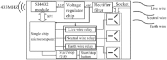
- the socket comprises a power module, a second radio frequency module, a single chip microcomputer and a switch module;
- the power module comprises a voltage regulator chip and a rectifier filter; one end of the second radio frequency module is electrically connected to a 3.3-V output terminal of the voltage regulator chip, and the other end of the second radio frequency module is electrically connected to the single chip microcomputer; a 5-V input terminal of the voltage regulator chip is electrically connected to the rectifier filter; and the single chip microcomputer is electrically connected to the switch module;
- the switch module comprises a relay structure and a button structure, wherein the relay structure comprises a start/stop relay; the button structure comprises the start/stop button; one end of the start/stop relay is electrically connected to the single chip microcomputer, and the other end of the start/stop relay is electrically connected to the start/stop button.
- the relay structure further comprises a live wire relay, a neutral wire relay and an earth wire relay
- the button structure further comprises a live wire button, a neutral wire button and an earth wire button
- one end of the live wire relay is electrically connected to the single chip microcomputer, and the other end of the live wire relay is electrically connected to the live wire button
- one end of the neutral wire relay is electrically connected to the single chip microcomputer, and the other end of the neutral wire relay is electrically connected to the neutral wire button
- one end of the earth wire relay is electrically connected to the single chip microcomputer, and the other end of the earth wire relay is electrically connected to the earth wire button.
- the single chip microcomputer is an ATmega32L microcontroller; the second radio frequency module is an SI4432 module, and the SI4432 module is electrically connected to the ATmega32L microcontroller via a Serial Peripheral Interface (SPI) serial port.
- SPI Serial Peripheral Interface
- a hidden handle is provided on a top of the support; a screw hole is provided on a bottom of the support, and the bottom of the support has a horizontal surface.
- a stop block is fixed on a surface of the cable; when the stop block abuts the casing, the winding reel stops winding.
- the present invention provides a control method for the intelligent electric winder, comprising:
- control method further comprises: when the host receives a wireless command from other equipment, controlling the winding reel to start or stop winding according to the wireless command.
- control method further comprises: the host starts a timing function; when a calculated cumulative time is greater than or equal to a preset time, the host switches an on or off of a power input voltage so that the winding reel is controlled to start or stop winding by the host.
- the host comprises the main control board and the communication board, wherein the drive structure is a motor, and an automatic detection of the main control board comprises:
- the host comprises the main control board and the communication board
- an upgrading of software of the communication board comprises:
- the host comprises the main control board and the communication board, wherein the communication of the communication board comprises:
- the socket further comprises the live wire relay, the neutral wire relay and the earth wire relay
- the control method for the intelligent electric winder further comprises:
- the invention has the following beneficial effects.
- the intelligent electric winder of the present invention comprises a support, a winder body and a control unit, wherein the winder body comprises a casing, a winding reel provided inside the casing, a drive structure connected to the winding reel, and a cable winds round the winding reel; the casing is fixedly connected the support; the drive structure is electrically connected to the control unit, and the control unit comprises: a socket for sending a wireless control signal through a start/stop button; and a host, for receiving the wireless control signal sent by the socket and controlling the winding reel to start or stop winding according to the wireless control signal; the drive structure is electrically connected to the control unit; the host is arranged inside the casing; the socket is arranged outside the casing; the start/stop button is provided on a surface of the socket, and the socket is connected to a free end of the cable.
- the present invention further provides a control method for the intelligent electric winder, in which the winding reel is controlled to start or stop winding by sending a wireless control signal, thereby real
- FIG. 1 shows a schematic diagram of an intelligent electric winder according to an embodiment of the present invention.
- FIG. 2 shows a block diagram of a circuit structure of a main control board according to an embodiment the present invention.
- FIG. 3 shows a block diagram of a circuit structure of a communication board according to an embodiment of the present invention.
- FIG. 4 shows a flow chart of a control method of the intelligent electric winder according to the present invention.
- FIG. 5 shows a software flowchart of the main control board according to an embodiment of the present invention.
- FIG. 6 shows a software flowchart of the communication board according to an embodiment of the present invention.
- FIG. 1 is a schematic diagram of an intelligent electric winder according to the embodiment of the present invention.
- this embodiment provides an intelligent electric winder, including a support 1 and a winder body 2 , where the winder body 2 includes a casing 3 , a winding reel provided inside the casing 3 , a drive structure connected to the winding reel, and a cable 6 winding on the winding reel; the casing 3 is fixedly connected to the support 1 ; the intelligent electric winder further includes a control unit, where the drive structure is electrically connected to the control unit, and the control unit includes:
- a host for receiving the wireless control signal sent by the socket 4 , and controlling the winding reel to start or stop winding according to the wireless control signal;
- the host is arranged inside the casing 3 ; the socket is arranged outside the casing 3 ; the start/stop button 5 is provided on a surface of the socket 4 , and the socket 4 is connected to a free end of the cable 6 .
- the socket 4 includes a radio frequency circuit, a Bluetooth circuit, or an infrared circuit for sending the wireless control signal.
- the wireless control signal is a radio frequency signal, a Bluetooth signal or an infrared signal.
- the wireless control signal is emitted by triggering the start/stop button 5 and then sent to the host via the socket 4 .
- the socket 4 far away from the winder body is provided with a start/stop button 5 to control the winder body 2 to retract the cable 6 , thereby greatly facilitating the use convenience of the intelligent electric winder.
- the winding of winding reel is started or stopped through the wireless control signal, so that the remote control for starting and stopping winding of the intelligent electric winder is realized through wireless communication, thereby facilitating the use convenience.
- FIG. 2 is a block diagram of a circuit structure of a main control board according to the embodiment the present invention
- FIG. 3 is a block diagram of a circuit structure of a communication board according to the embodiment of the present invention.
- the host includes a main control board and a communication board.
- the main control board includes a power module, a MOS transistor drive and a first microprocessor, where an input terminal of the power module is electrically connected to an external rectifier module; a 3.3-V output terminal of the power module is electrically connected to the first microprocessor; a 5-V output terminal of the power module is electrically connected to a control electrode of the MOS transistor drive; an input electrode of the MOS transistor drive is electrically connected to the first microprocessor, and an output electrode of the MOS transistor drive is electrically connected to the drive structure.
- the communication board includes a first radio frequency module and a second microprocessor, where the first radio frequency module is electrically connected to the second microprocessor; the second microprocessor is further electrically connected to the first microprocessor; the first radio frequency module is further electrically connected to the 3.3-V output of the power module.
- the host includes the main control board and the communication board, and the drive structure in this embodiment is a motor.
- the main control board includes the following components:
- (1) power supply module used to provide 5-V power input voltage to the main control board and the socket 4 ;
- the power supply module is a voltage transformer/regulator module;
- MOS transistor drive used to drive the motor and adjust the speed thereof
- sampling resistor used for overcurrent protection for the motor.
- first microprocessor used to control the motor rotation and protect the motor; the first microprocessor is a Microcontroller Unit (MCU).
- MCU Microcontroller Unit
- the communication board includes the following components:
- first radio frequency module used for radio frequency communication with the socket 4 , where the radio frequency communication includes the reception and transmission of uplink and downlink data signals, and the first radio frequency module is a wireless 433M RF module, and more particularly is an SI4432 module;
- the wireless module used to communicate with a mobile phone application program (APP) or a third-party voice equipment through wireless network connection, where the communication includes the reception and transmission of uplink and downlink data signals.
- the wireless module may be one or a combination of a WIFI module and a Bluetooth module;
- the third-party voice equipment may be Tmall Genie, Huawei Xiaoai, Amazon alexa, Google home assistant, etc.;
- the second microprocessor used to process data communication between Radio Frequency (RF) and wireless network (e.g., WIFI network); the second microprocessor is an MCU.
- RF Radio Frequency
- WIFI wireless network
- the communication board further comprises a wireless module for receiving a wireless command sent by other equipment and sending out the wireless command, so that the first microprocessor controls the winding reel to start or stop winding according to the wireless command; the wireless module is electrically connected to the second microprocessor.
- the other equipment is a wireless intelligent terminal device other than the intelligent electric winder, such as a mobile phone or third-party voice equipment.
- the intelligent electric winder of this embodiment is an intelligent electric winder that can be remotely controlled by WIFI and the third-party voice equipment, and WIFI networking technologies are applied to the electric winders, thereby greatly facilitating the use and remote control of users.
- the wireless module is a WIFI module or a Bluetooth module
- the power module is a voltage transformer/regulator module.
- the wireless command is a WIFI command or a Bluetooth command, which is sent by the mobile phone APP or the third-party voice equipment. After being received by the WIFI module or the Bluetooth module, the wireless command is sent to the second microprocessor.
- the main control board further includes a sampling resistor; one end of the sampling resistor is electrically connected to the input electrode of the MOS transistor drive, and the other end of the sampling resistor is electrically connected to the first microprocessor.
- the intelligent electric winder of the embodiment sends a signal to the communication board according to an action signal of the start/stop button 5 of the socket 4 ; when the SI4432 module of the communication board receives the corresponding signal and sends it to the MCU, the MCU controls the winder body 2 to start or stop according to the signal.
- the socket 4 includes a power module, a second radio frequency module, a single chip microcomputer and a switch module, where the power module includes a voltage regulator chip and a rectifier filter; one end of the second radio frequency module is electrically connected to a 3.3-V output terminal of the voltage regulator chip, and the other end of the second radio frequency module is electrically connected to the single chip microcomputer; a 5-V input terminal of the voltage regulator chip is electrically connected to the rectification filter; the single chip microcomputer is further electrically connected to the switch module;
- the switch module includes a relay structure and a button structure, where the relay structure includes a start/stop relay, and the button structure includes the start/stop button 5 ; one end of the start/stop relay is electrically connected to the single chip microcomputer, and the other end of the start/stop relay is electrically connected to the start/stop button 5 .
- a control part of the socket 4 mainly includes an SI4432 module (a radio frequency module SI4432) and a single chip microcomputer (an avr single chip microcomputer).
- the SI4432 module is mainly used to send and receive wireless control signals; the avr single chip microcomputer is mainly used to control a three-way AC power supply; signals of the SI4432 module is communicated with that of the single chip microcomputer via the SPI serial port.
- the socket 4 includes the following components:
- (1) power module mainly used to generate the power required by the socket 4 .
- a 120 V/220 V AC power supply is first stepped down and rectified into 5-V DC, and then converted into +3.3-V for use of all parts;
- the second radio frequency module is a radio frequency transceiver module, and more particularly is an SI4432 module.
- the second radio frequency module is mainly configured to receive the wireless command sent from the main control board, transmit the received wireless control signal to the single chip microcomputer through the SPI serial port, and send the wireless control signal to the main control board, so that the main control board controls the winding reel to start or stop winding according to the wireless control signal;
- the single chip microcomputer is also called a main control single chip microcomputer module, and more particularly is an ATmega32L microcontroller of ATMEL corporation.
- the single chip microcomputer is mainly configured to send corresponding commands to the corresponding relays according to the information transmitted from the SI4432 module to control the on or off of the three power supplies.
- the relay structure further includes a live wire relay, a neutral wire relay, and an earth wire relay
- the button structure further includes a live wire button, a neutral wire button, and an earth wire button
- one end of the live wire relay is electrically connected to the single chip microcomputer, and the other end of the live wire relay is electrically connected to the live wire button
- one end of the neutral wire relay is electrically connected to the single chip microcomputer, and the other end of the neutral wire relay is electrically connected to the neutral wire button
- one end of the earth wire relay is electrically connected to the single chip microcomputer, and the other end of the earth wire relay is electrically connected to the earth wire button.
- the socket 4 receives the signal from the main control board and sends the signal to the ATmega32L microcontroller, and the ATmega32L microcontroller controls on or off of the three relays (the live wire relay, the neutral wire relay and the earth wire relay) according to the signal, to further control on or off of an output AC power.
- the ATmega32L microcontroller controls on or off of the three relays (the live wire relay, the neutral wire relay and the earth wire relay) according to the signal, to further control on or off of an output AC power.
- the single chip microcomputer is an ATmega32L microcontroller; the second radio frequency module is an SI4432 module, and the SI4432 module is electrically connected to the ATmega32L microcontroller through the SPI serial port.
- the SPI is a high-speed, full-duplex, synchronous communication bus; it only occupies four wires on the pins of the chip, thereby saving pins of the chip, saving place and providing convenience for arranging a Printed Circuit Board (PCB).
- PCB Printed Circuit Board
- a hidden handle is provided on a top of the support 1 ; a screw hole is provided on a bottom of the support 1 , and the bottom of the support 1 has a horizontal surface.
- the intelligent electric winder of this embodiment adopts a portable design, which can be fixed on a wall or ceiling via screw holes of the base, or placed on the ground through the horizontal bottom surface; it is convenient to move the winder body due to the arrangement of the hidden handle.
- the intelligent electric winder of this embodiment adopts a structure in which a support 1 is combined with a winding reel and a casing 3 ; the support 1 is provided with a hidden handle to facilitate lifting and moving of the winder body, and a shape of the winder body 2 is similar to a sphere in which two parts are cut off.
- a stop block 7 is fixed on a surface of the cable 6 ; when the stop block 7 abuts the casing 3 , the winding reel stops winding.
- the special situation in which the control unit fails to work is dealt by arranging the stop block 7 , which provides an additional safety protection for the intelligent electric winder.
- the intelligent electric winder of this embodiment has a portable design and can realize remote and intelligent control through either the wireless communication, or the mobile APP or the third-party voice equipment capable for sending a third-party voice, so that the intelligent electric winder is controlled to start or stop winding.
- FIG. 4 is a flow chart of a control method for the intelligent electric winder according to the present invention.
- control method for the intelligent electric winder in this embodiment is based on the above-mentioned intelligent electric winder, and includes the following steps:
- the winding of the winding reel is started or stopped through the wireless control signal, thereby realizing a remote switch function of the intelligent electric winder, and facilitating the use thereof.
- control method of the intelligent electric winder further includes a step that when the host receives a wireless command sent by other equipment, the winding reel is controlled to start or stop winding according to the wireless command.
- control method for the intelligent electric winder further includes the following steps: the host starts a timing function; when a calculated cumulative time is greater than or equal to a preset time, the host switches the on or off of the power input voltage, so that the winding reel is switched to start or stop winding by the host.
- the control method for the intelligent electric winder of the embodiment can not only remotely control the winder body 2 to automatically retract the cable 6 through the socket 4 , the mobile phone APP, or the third-party voice equipment, but also simultaneously control a plurality of sockets 4 (that is, the mobile phone APP or the third-party voice equipment can simultaneously wirelessly connect a plurality of intelligent electric winders and perform remote control) to switch on or off of the power and set the time duration of the on and off state of the power respectively.
- the socket 4 receives the signal sent from the main control board, and controls the on and off state of the three relays according to the signal, so as to further control the on and off state of the output AC power.
- FIG. 5 is a software flowchart according to an embodiment of the main control board of the present invention.
- the host includes the main control board and the communication board; the drive structure is a motor, and an automatic detection of the main control board includes the following steps.
- a power-on initialization is carried out to obtain test signals, and whether the power input voltage is within a preset range is determined according to the test signal; if yes, the motor is started and controlled to be in a constant speed state; otherwise, the power input voltage of the main control board is cut off;
- the automatic detection of the main control board can maintain the main control board in a stable working state for a long time; besides, when an abnormal situation is found, the main control board is turned off immediately, so as to protect the intelligence electric winder, thereby greatly extending a service life of the intelligent electric winder.
- FIG. 6 is a software flowchart of the communication board according to the embodiment of the present invention.
- the host includes the main control board and the communication board; steps of upgrading the software of the communication board are described as follows.
- the power-on initialization is carried out, and the wireless network connection of the software is confirmed; whether the current version of the software is the latest version is detected through the wireless network; if not, the software is controlled to upgrade the current version to the latest version through the wireless network.
- the upgrading of the software of the communication board can detect whether the software of the communication board is the latest version in real time, and update it in time if the current version is not the latest version, so as to further improve the functions of the communication board, and performs all-round remote control for the intelligent electric winder.
- the host includes the main control board and the communication board, and the communication of the communication board includes the following steps.
- the power-on initialization is carried out and the wireless network connection of the software is confirmed;
- the socket 4 further includes the live wire relay, the neutral wire relay and the earth wire relay, and the control method for the intelligent electric winder further includes the following steps.
- An on or off signal received through the wireless network is converted into the wireless control signal, and sent to the socket 4 by the host, so that the socket 4 respectively controls on or off state of the live wire relay, the neutral wire relay and the earth wire relay according to the on or off signal.
- the socket 4 receives the signal sent from the main control board and sends the signal to the ATmega32L microcontroller; the ATmega32L microcontroller controls the on or off state of 3 relays (the live wire relay, the neutral wire relay and the earth wire relay) according to the signal, so as to further control the on or off of the output AC power.
- orientational terms such as “front”, “back”, “up”, “down”, “left”, “right”, “horizontal”, “vertical” and “top”, “bottom”, are usually based on the orientational or positional relationship shown in the drawings, and only intended to simplify the description of the invention. Unless specified, these orientational terms do not indicate and imply that devices or elements must have a specific orientation or be constructed and operated in a specific orientation, and therefore these orientational terms cannot be construed as limiting the scope of protection of the invention; the orientational terms “inside” and “outside” is relative to the contour of each component.
- spatial relative terms can be used herein, such as “above”, “on”, “upper”, etc., are used to describe the spatial relationship between a device and other devices or between a feature and other features shown in the drawings. It should be understood that spatial relative terms are intended to encompass different orientations in use or operation in addition to the orientation of the device shown in the drawings. For example, if a device in the drawing is turned upside down, the device described as “above other equipment or configuration” or “on other equipment or configuration” will then be positioned as “below other equipment or configuration” or “under other equipment or structures”. Therefore, the exemplary spatial relative term “above” may include orientations of both “above” and “below”. The device can also be positioned in other different ways (being rotated 90 degrees or at other orientations), and the relative description of the space used herein should be explained accordingly.
Landscapes
- Engineering & Computer Science (AREA)
- Computer Networks & Wireless Communication (AREA)
- Signal Processing (AREA)
- Selective Calling Equipment (AREA)
Abstract
Description
-
- a casing fixedly connected to the support,
- a winding reel provided inside the casing,
- a drive structure connected to the winding reel, and
- a cable winded around the winding reel; and
-
- a socket for sending a wireless control signal via a start/stop button; and
- a host for receiving the wireless control signal sent by the socket, and controlling the winding reel to start or stop winding according to the wireless control signal;
Claims (6)
Applications Claiming Priority (2)
| Application Number | Priority Date | Filing Date | Title |
|---|---|---|---|
| CN202010212160.8A CN111252631B (en) | 2020-03-24 | 2020-03-24 | Intelligent electric winder and control method thereof |
| CN202010212160.8 | 2020-03-24 |
Publications (2)
| Publication Number | Publication Date |
|---|---|
| US20210300719A1 US20210300719A1 (en) | 2021-09-30 |
| US11565908B2 true US11565908B2 (en) | 2023-01-31 |
Family
ID=70470962
Family Applications (1)
| Application Number | Title | Priority Date | Filing Date |
|---|---|---|---|
| US16/861,091 Active 2041-03-09 US11565908B2 (en) | 2020-03-24 | 2020-04-28 | Intelligent electric winder and control method therefor |
Country Status (4)
| Country | Link |
|---|---|
| US (1) | US11565908B2 (en) |
| EP (1) | EP3885299A1 (en) |
| CN (1) | CN111252631B (en) |
| AU (1) | AU2020202795A1 (en) |
Cited By (2)
| Publication number | Priority date | Publication date | Assignee | Title |
|---|---|---|---|---|
| EP2356184B2 (en) † | 2008-11-18 | 2021-06-16 | Sun Chemical Corporation | Printing ink and coating compositions containing derivatives of starch and modified starch |
| US20220048727A1 (en) * | 2021-02-02 | 2022-02-17 | Intradin (Huzhou) Precision Technology Co.,Ltd. | Electric winder and method for controlling same |
Families Citing this family (3)
| Publication number | Priority date | Publication date | Assignee | Title |
|---|---|---|---|---|
| CN113001352B (en) * | 2021-03-22 | 2022-02-22 | 吾尚良品环境服务(上海)有限公司 | A spooler for stone material is polished |
| JP2023105553A (en) * | 2022-01-19 | 2023-07-31 | グローブライド株式会社 | Terminal control program, terminal device, and reel information management system |
| CN117055410A (en) * | 2023-09-04 | 2023-11-14 | 深圳市飚龙科技有限公司 | An electric window opening machine control system |
Citations (7)
| Publication number | Priority date | Publication date | Assignee | Title |
|---|---|---|---|---|
| US20060027155A1 (en) * | 2004-08-06 | 2006-02-09 | John Welch | System and method for a tow-rope retraction device for watercraft |
| US20100224843A1 (en) * | 2004-08-06 | 2010-09-09 | Global Innovative Sports Incorporated | Winch System Safety Device Controlled by Towrope Angle |
| US20130032654A1 (en) * | 2011-08-05 | 2013-02-07 | Great Stuff, Inc. | Control system for electrical cord reel |
| US20140217225A1 (en) * | 2011-06-17 | 2014-08-07 | Ipalco B.V. | Device for unwinding and winding up one or more lines |
| CN106044370A (en) | 2016-08-24 | 2016-10-26 | 北京灵铱科技有限公司 | Winder device with remote action control function |
| US20190271169A1 (en) * | 2013-10-13 | 2019-09-05 | Maytronics Ltd. | Pool cleaning robot and a method for sensing a cleanliness of a filtering unit |
| CN210162954U (en) | 2019-07-11 | 2020-03-20 | 四川永贵科技有限公司 | Automatic winding displacement cable dish |
Family Cites Families (12)
| Publication number | Priority date | Publication date | Assignee | Title |
|---|---|---|---|---|
| MXPA05009774A (en) * | 2003-03-13 | 2006-03-08 | Great Stuff Inc | Remote control for hose operation. |
| EP2258647A1 (en) * | 2004-07-01 | 2010-12-08 | Great Stuff, Inc. | System and method for controlling spooling of linear material |
| WO2012060008A1 (en) * | 2010-11-05 | 2012-05-10 | トヨタ自動車株式会社 | Electric wire storage device and vehicle mounted with the same |
| US8695912B2 (en) * | 2011-04-19 | 2014-04-15 | Great Stuff, Inc. | Reel systems and methods for monitoring and controlling linear material slack |
| US20140021284A1 (en) * | 2012-07-20 | 2014-01-23 | Great Stuff, Inc. | Reel with manually actuated retraction system |
| CN103964265A (en) * | 2014-04-16 | 2014-08-06 | 泰豪电源技术有限公司 | Wireless remote control cable hoist device |
| CN104961006B (en) * | 2015-06-10 | 2019-07-23 | 国网河南许昌县供电公司 | Power equipment automatic deploying and retracting line control method |
| CN205442261U (en) * | 2016-04-11 | 2016-08-10 | 河北梅特电气设备有限公司 | Automatic cable - line device of remote control |
| CN205998763U (en) * | 2016-08-24 | 2017-03-08 | 北京灵铱科技有限公司 | A kind of can remote control action bobbin winder device |
| CN108419502A (en) * | 2017-12-15 | 2018-08-21 | 宁波大叶园林设备股份有限公司 | Has the agricultural intelligence gardens working machine of wireless telecommunications remote control circuit and multifunctional platform |
| CN108726286A (en) * | 2018-06-19 | 2018-11-02 | 国网冀北电力有限公司唐山供电公司 | A kind of movable type cable disk and safety custody method |
| CN213112054U (en) * | 2020-03-24 | 2021-05-04 | 士商(湖州)精密技术有限公司 | Intelligent electric winder |
-
2020
- 2020-03-24 CN CN202010212160.8A patent/CN111252631B/en active Active
- 2020-04-28 EP EP20171709.7A patent/EP3885299A1/en not_active Withdrawn
- 2020-04-28 US US16/861,091 patent/US11565908B2/en active Active
- 2020-04-28 AU AU2020202795A patent/AU2020202795A1/en not_active Abandoned
Patent Citations (7)
| Publication number | Priority date | Publication date | Assignee | Title |
|---|---|---|---|---|
| US20060027155A1 (en) * | 2004-08-06 | 2006-02-09 | John Welch | System and method for a tow-rope retraction device for watercraft |
| US20100224843A1 (en) * | 2004-08-06 | 2010-09-09 | Global Innovative Sports Incorporated | Winch System Safety Device Controlled by Towrope Angle |
| US20140217225A1 (en) * | 2011-06-17 | 2014-08-07 | Ipalco B.V. | Device for unwinding and winding up one or more lines |
| US20130032654A1 (en) * | 2011-08-05 | 2013-02-07 | Great Stuff, Inc. | Control system for electrical cord reel |
| US20190271169A1 (en) * | 2013-10-13 | 2019-09-05 | Maytronics Ltd. | Pool cleaning robot and a method for sensing a cleanliness of a filtering unit |
| CN106044370A (en) | 2016-08-24 | 2016-10-26 | 北京灵铱科技有限公司 | Winder device with remote action control function |
| CN210162954U (en) | 2019-07-11 | 2020-03-20 | 四川永贵科技有限公司 | Automatic winding displacement cable dish |
Cited By (3)
| Publication number | Priority date | Publication date | Assignee | Title |
|---|---|---|---|---|
| EP2356184B2 (en) † | 2008-11-18 | 2021-06-16 | Sun Chemical Corporation | Printing ink and coating compositions containing derivatives of starch and modified starch |
| US20220048727A1 (en) * | 2021-02-02 | 2022-02-17 | Intradin (Huzhou) Precision Technology Co.,Ltd. | Electric winder and method for controlling same |
| US11878896B2 (en) * | 2021-02-02 | 2024-01-23 | Intradin (Huzhou) Precision Technology Co., Ltd. | Electric winder and method for controlling same |
Also Published As
| Publication number | Publication date |
|---|---|
| EP3885299A1 (en) | 2021-09-29 |
| CN111252631B (en) | 2024-08-09 |
| AU2020202795A1 (en) | 2021-10-14 |
| US20210300719A1 (en) | 2021-09-30 |
| CN111252631A (en) | 2020-06-09 |
Similar Documents
| Publication | Publication Date | Title |
|---|---|---|
| US11565908B2 (en) | Intelligent electric winder and control method therefor | |
| US9852617B2 (en) | Inverter device | |
| US8093751B1 (en) | Method and system for controlling power to an electrically powered device | |
| CN106299910A (en) | A kind of smart jack | |
| US10431940B1 (en) | Power receptacle with wireless control | |
| EP2587627A1 (en) | Electronic device, wireless power supply system thereof and wireless power supply method thereof | |
| CN105137841A (en) | Remote control method and device based on intelligent socket | |
| CN112114554B (en) | Wireless control system and method for power supply on-off of power equipment | |
| JP2015035911A5 (en) | ||
| CN204242379U (en) | Remote control device and system for electrical equipment | |
| EP2975855A1 (en) | Operation terminal control system | |
| KR200428011Y1 (en) | Multi outlet device with standby power off function | |
| CN213112054U (en) | Intelligent electric winder | |
| CN210430691U (en) | Isolation switch control cabinet for substation operation | |
| KR20100116268A (en) | Apparatus and method of control electric device in system for cut off function of waiting power supply | |
| WO2025156681A1 (en) | Programmable dm based on infrared communication, and programming method | |
| CN106249612A (en) | The intelligent controller being easy to use | |
| EP4037120B1 (en) | Electric winder and method for controlling same | |
| KR101820476B1 (en) | Apparatus for Monitoring Charge of Mobile Terminal Battery | |
| KR101818707B1 (en) | Standby current cut-off system for the EMS | |
| JP2014049857A (en) | Radio communication device | |
| JP7043473B2 (en) | Switch device | |
| CN211320508U (en) | Intelligent socket and wireless communication system | |
| CN210295388U (en) | Intelligent control socket | |
| US20240328615A1 (en) | Ceiling-fan lamp with multiple control modes |
Legal Events
| Date | Code | Title | Description |
|---|---|---|---|
| AS | Assignment |
Owner name: INTRADIN (HUZHOU) PRECISION TECHNOLOGY CO.,LTD., CHINA Free format text: ASSIGNMENT OF ASSIGNORS INTEREST;ASSIGNORS:QIAO, XUETAO;WANG, GAOFENG;REEL/FRAME:052518/0463 Effective date: 20200320 |
|
| FEPP | Fee payment procedure |
Free format text: ENTITY STATUS SET TO UNDISCOUNTED (ORIGINAL EVENT CODE: BIG.); ENTITY STATUS OF PATENT OWNER: SMALL ENTITY |
|
| FEPP | Fee payment procedure |
Free format text: ENTITY STATUS SET TO SMALL (ORIGINAL EVENT CODE: SMAL); ENTITY STATUS OF PATENT OWNER: SMALL ENTITY |
|
| STPP | Information on status: patent application and granting procedure in general |
Free format text: DOCKETED NEW CASE - READY FOR EXAMINATION |
|
| STPP | Information on status: patent application and granting procedure in general |
Free format text: NON FINAL ACTION MAILED |
|
| STPP | Information on status: patent application and granting procedure in general |
Free format text: RESPONSE TO NON-FINAL OFFICE ACTION ENTERED AND FORWARDED TO EXAMINER |
|
| STPP | Information on status: patent application and granting procedure in general |
Free format text: FINAL REJECTION MAILED |
|
| STPP | Information on status: patent application and granting procedure in general |
Free format text: RESPONSE AFTER FINAL ACTION FORWARDED TO EXAMINER |
|
| STPP | Information on status: patent application and granting procedure in general |
Free format text: NOTICE OF ALLOWANCE MAILED -- APPLICATION RECEIVED IN OFFICE OF PUBLICATIONS |
|
| STPP | Information on status: patent application and granting procedure in general |
Free format text: PUBLICATIONS -- ISSUE FEE PAYMENT VERIFIED |
|
| STCF | Information on status: patent grant |
Free format text: PATENTED CASE |
|
| MAFP | Maintenance fee payment |
Free format text: PAYMENT OF MAINTENANCE FEE, 4TH YR, SMALL ENTITY (ORIGINAL EVENT CODE: M2551); ENTITY STATUS OF PATENT OWNER: SMALL ENTITY Year of fee payment: 4 |