US11560846B2 - Combined heat and power system - Google Patents
Combined heat and power system Download PDFInfo
- Publication number
- US11560846B2 US11560846B2 US17/045,857 US201917045857A US11560846B2 US 11560846 B2 US11560846 B2 US 11560846B2 US 201917045857 A US201917045857 A US 201917045857A US 11560846 B2 US11560846 B2 US 11560846B2
- Authority
- US
- United States
- Prior art keywords
- recuperator
- turbine
- combustor
- gas
- channel
- Prior art date
- Legal status (The legal status is an assumption and is not a legal conclusion. Google has not performed a legal analysis and makes no representation as to the accuracy of the status listed.)
- Active, expires
Links
Images


Classifications
-
- F—MECHANICAL ENGINEERING; LIGHTING; HEATING; WEAPONS; BLASTING
- F02—COMBUSTION ENGINES; HOT-GAS OR COMBUSTION-PRODUCT ENGINE PLANTS
- F02C—GAS-TURBINE PLANTS; AIR INTAKES FOR JET-PROPULSION PLANTS; CONTROLLING FUEL SUPPLY IN AIR-BREATHING JET-PROPULSION PLANTS
- F02C1/00—Gas-turbine plants characterised by the use of hot gases or unheated pressurised gases, as the working fluid
- F02C1/04—Gas-turbine plants characterised by the use of hot gases or unheated pressurised gases, as the working fluid the working fluid being heated indirectly
- F02C1/05—Gas-turbine plants characterised by the use of hot gases or unheated pressurised gases, as the working fluid the working fluid being heated indirectly characterised by the type or source of heat, e.g. using nuclear or solar energy
- F02C1/06—Gas-turbine plants characterised by the use of hot gases or unheated pressurised gases, as the working fluid the working fluid being heated indirectly characterised by the type or source of heat, e.g. using nuclear or solar energy using reheated exhaust gas
-
- F—MECHANICAL ENGINEERING; LIGHTING; HEATING; WEAPONS; BLASTING
- F02—COMBUSTION ENGINES; HOT-GAS OR COMBUSTION-PRODUCT ENGINE PLANTS
- F02C—GAS-TURBINE PLANTS; AIR INTAKES FOR JET-PROPULSION PLANTS; CONTROLLING FUEL SUPPLY IN AIR-BREATHING JET-PROPULSION PLANTS
- F02C7/00—Features, components parts, details or accessories, not provided for in, or of interest apart form groups F02C1/00 - F02C6/00; Air intakes for jet-propulsion plants
- F02C7/08—Heating air supply before combustion, e.g. by exhaust gases
- F02C7/10—Heating air supply before combustion, e.g. by exhaust gases by means of regenerative heat-exchangers
-
- B—PERFORMING OPERATIONS; TRANSPORTING
- B22—CASTING; POWDER METALLURGY
- B22F—WORKING METALLIC POWDER; MANUFACTURE OF ARTICLES FROM METALLIC POWDER; MAKING METALLIC POWDER; APPARATUS OR DEVICES SPECIALLY ADAPTED FOR METALLIC POWDER
- B22F5/00—Manufacture of workpieces or articles from metallic powder characterised by the special shape of the product
- B22F5/009—Manufacture of workpieces or articles from metallic powder characterised by the special shape of the product of turbine components other than turbine blades
-
- B—PERFORMING OPERATIONS; TRANSPORTING
- B33—ADDITIVE MANUFACTURING TECHNOLOGY
- B33Y—ADDITIVE MANUFACTURING, i.e. MANUFACTURING OF THREE-DIMENSIONAL [3D] OBJECTS BY ADDITIVE DEPOSITION, ADDITIVE AGGLOMERATION OR ADDITIVE LAYERING, e.g. BY 3D PRINTING, STEREOLITHOGRAPHY OR SELECTIVE LASER SINTERING
- B33Y50/00—Data acquisition or data processing for additive manufacturing
-
- B—PERFORMING OPERATIONS; TRANSPORTING
- B33—ADDITIVE MANUFACTURING TECHNOLOGY
- B33Y—ADDITIVE MANUFACTURING, i.e. MANUFACTURING OF THREE-DIMENSIONAL [3D] OBJECTS BY ADDITIVE DEPOSITION, ADDITIVE AGGLOMERATION OR ADDITIVE LAYERING, e.g. BY 3D PRINTING, STEREOLITHOGRAPHY OR SELECTIVE LASER SINTERING
- B33Y80/00—Products made by additive manufacturing
-
- F—MECHANICAL ENGINEERING; LIGHTING; HEATING; WEAPONS; BLASTING
- F02—COMBUSTION ENGINES; HOT-GAS OR COMBUSTION-PRODUCT ENGINE PLANTS
- F02C—GAS-TURBINE PLANTS; AIR INTAKES FOR JET-PROPULSION PLANTS; CONTROLLING FUEL SUPPLY IN AIR-BREATHING JET-PROPULSION PLANTS
- F02C1/00—Gas-turbine plants characterised by the use of hot gases or unheated pressurised gases, as the working fluid
- F02C1/04—Gas-turbine plants characterised by the use of hot gases or unheated pressurised gases, as the working fluid the working fluid being heated indirectly
- F02C1/08—Semi-closed cycles
-
- F—MECHANICAL ENGINEERING; LIGHTING; HEATING; WEAPONS; BLASTING
- F02—COMBUSTION ENGINES; HOT-GAS OR COMBUSTION-PRODUCT ENGINE PLANTS
- F02C—GAS-TURBINE PLANTS; AIR INTAKES FOR JET-PROPULSION PLANTS; CONTROLLING FUEL SUPPLY IN AIR-BREATHING JET-PROPULSION PLANTS
- F02C3/00—Gas-turbine plants characterised by the use of combustion products as the working fluid
- F02C3/14—Gas-turbine plants characterised by the use of combustion products as the working fluid characterised by the arrangement of the combustion chamber in the plant
- F02C3/145—Gas-turbine plants characterised by the use of combustion products as the working fluid characterised by the arrangement of the combustion chamber in the plant the combustion chamber being in the reverse flow-type
-
- F—MECHANICAL ENGINEERING; LIGHTING; HEATING; WEAPONS; BLASTING
- F02—COMBUSTION ENGINES; HOT-GAS OR COMBUSTION-PRODUCT ENGINE PLANTS
- F02C—GAS-TURBINE PLANTS; AIR INTAKES FOR JET-PROPULSION PLANTS; CONTROLLING FUEL SUPPLY IN AIR-BREATHING JET-PROPULSION PLANTS
- F02C7/00—Features, components parts, details or accessories, not provided for in, or of interest apart form groups F02C1/00 - F02C6/00; Air intakes for jet-propulsion plants
- F02C7/08—Heating air supply before combustion, e.g. by exhaust gases
-
- F—MECHANICAL ENGINEERING; LIGHTING; HEATING; WEAPONS; BLASTING
- F02—COMBUSTION ENGINES; HOT-GAS OR COMBUSTION-PRODUCT ENGINE PLANTS
- F02C—GAS-TURBINE PLANTS; AIR INTAKES FOR JET-PROPULSION PLANTS; CONTROLLING FUEL SUPPLY IN AIR-BREATHING JET-PROPULSION PLANTS
- F02C9/00—Controlling gas-turbine plants; Controlling fuel supply in air- breathing jet-propulsion plants
- F02C9/16—Control of working fluid flow
- F02C9/18—Control of working fluid flow by bleeding, bypassing or acting on variable working fluid interconnections between turbines or compressors or their stages
-
- F—MECHANICAL ENGINEERING; LIGHTING; HEATING; WEAPONS; BLASTING
- F28—HEAT EXCHANGE IN GENERAL
- F28D—HEAT-EXCHANGE APPARATUS, NOT PROVIDED FOR IN ANOTHER SUBCLASS, IN WHICH THE HEAT-EXCHANGE MEDIA DO NOT COME INTO DIRECT CONTACT
- F28D21/00—Heat-exchange apparatus not covered by any of the groups F28D1/00 - F28D20/00
- F28D21/0001—Recuperative heat exchangers
- F28D21/0003—Recuperative heat exchangers the heat being recuperated from exhaust gases
-
- F—MECHANICAL ENGINEERING; LIGHTING; HEATING; WEAPONS; BLASTING
- F28—HEAT EXCHANGE IN GENERAL
- F28D—HEAT-EXCHANGE APPARATUS, NOT PROVIDED FOR IN ANOTHER SUBCLASS, IN WHICH THE HEAT-EXCHANGE MEDIA DO NOT COME INTO DIRECT CONTACT
- F28D9/00—Heat-exchange apparatus having stationary plate-like or laminated conduit assemblies for both heat-exchange media, the media being in contact with different sides of a conduit wall
- F28D9/04—Heat-exchange apparatus having stationary plate-like or laminated conduit assemblies for both heat-exchange media, the media being in contact with different sides of a conduit wall the conduits being formed by spirally-wound plates or laminae
-
- B—PERFORMING OPERATIONS; TRANSPORTING
- B22—CASTING; POWDER METALLURGY
- B22F—WORKING METALLIC POWDER; MANUFACTURE OF ARTICLES FROM METALLIC POWDER; MAKING METALLIC POWDER; APPARATUS OR DEVICES SPECIALLY ADAPTED FOR METALLIC POWDER
- B22F10/00—Additive manufacturing of workpieces or articles from metallic powder
- B22F10/20—Direct sintering or melting
- B22F10/28—Powder bed fusion, e.g. selective laser melting [SLM] or electron beam melting [EBM]
-
- F—MECHANICAL ENGINEERING; LIGHTING; HEATING; WEAPONS; BLASTING
- F02—COMBUSTION ENGINES; HOT-GAS OR COMBUSTION-PRODUCT ENGINE PLANTS
- F02C—GAS-TURBINE PLANTS; AIR INTAKES FOR JET-PROPULSION PLANTS; CONTROLLING FUEL SUPPLY IN AIR-BREATHING JET-PROPULSION PLANTS
- F02C6/00—Plural gas-turbine plants; Combinations of gas-turbine plants with other apparatus; Adaptations of gas-turbine plants for special use
- F02C6/18—Plural gas-turbine plants; Combinations of gas-turbine plants with other apparatus; Adaptations of gas-turbine plants for special use using the waste heat of gas-turbine plants outside the plants themselves, e.g. gas-turbine power heat plants
-
- F—MECHANICAL ENGINEERING; LIGHTING; HEATING; WEAPONS; BLASTING
- F02—COMBUSTION ENGINES; HOT-GAS OR COMBUSTION-PRODUCT ENGINE PLANTS
- F02C—GAS-TURBINE PLANTS; AIR INTAKES FOR JET-PROPULSION PLANTS; CONTROLLING FUEL SUPPLY IN AIR-BREATHING JET-PROPULSION PLANTS
- F02C9/00—Controlling gas-turbine plants; Controlling fuel supply in air- breathing jet-propulsion plants
- F02C9/48—Control of fuel supply conjointly with another control of the plant
- F02C9/50—Control of fuel supply conjointly with another control of the plant with control of working fluid flow
- F02C9/52—Control of fuel supply conjointly with another control of the plant with control of working fluid flow by bleeding or by-passing the working fluid
-
- F—MECHANICAL ENGINEERING; LIGHTING; HEATING; WEAPONS; BLASTING
- F05—INDEXING SCHEMES RELATING TO ENGINES OR PUMPS IN VARIOUS SUBCLASSES OF CLASSES F01-F04
- F05D—INDEXING SCHEME FOR ASPECTS RELATING TO NON-POSITIVE-DISPLACEMENT MACHINES OR ENGINES, GAS-TURBINES OR JET-PROPULSION PLANTS
- F05D2230/00—Manufacture
- F05D2230/20—Manufacture essentially without removing material
-
- F—MECHANICAL ENGINEERING; LIGHTING; HEATING; WEAPONS; BLASTING
- F05—INDEXING SCHEMES RELATING TO ENGINES OR PUMPS IN VARIOUS SUBCLASSES OF CLASSES F01-F04
- F05D—INDEXING SCHEME FOR ASPECTS RELATING TO NON-POSITIVE-DISPLACEMENT MACHINES OR ENGINES, GAS-TURBINES OR JET-PROPULSION PLANTS
- F05D2230/00—Manufacture
- F05D2230/30—Manufacture with deposition of material
- F05D2230/31—Layer deposition
-
- F—MECHANICAL ENGINEERING; LIGHTING; HEATING; WEAPONS; BLASTING
- F05—INDEXING SCHEMES RELATING TO ENGINES OR PUMPS IN VARIOUS SUBCLASSES OF CLASSES F01-F04
- F05D—INDEXING SCHEME FOR ASPECTS RELATING TO NON-POSITIVE-DISPLACEMENT MACHINES OR ENGINES, GAS-TURBINES OR JET-PROPULSION PLANTS
- F05D2230/00—Manufacture
- F05D2230/50—Building or constructing in particular ways
- F05D2230/53—Building or constructing in particular ways by integrally manufacturing a component, e.g. by milling from a billet or one piece construction
-
- F—MECHANICAL ENGINEERING; LIGHTING; HEATING; WEAPONS; BLASTING
- F05—INDEXING SCHEMES RELATING TO ENGINES OR PUMPS IN VARIOUS SUBCLASSES OF CLASSES F01-F04
- F05D—INDEXING SCHEME FOR ASPECTS RELATING TO NON-POSITIVE-DISPLACEMENT MACHINES OR ENGINES, GAS-TURBINES OR JET-PROPULSION PLANTS
- F05D2240/00—Components
- F05D2240/35—Combustors or associated equipment
-
- F—MECHANICAL ENGINEERING; LIGHTING; HEATING; WEAPONS; BLASTING
- F05—INDEXING SCHEMES RELATING TO ENGINES OR PUMPS IN VARIOUS SUBCLASSES OF CLASSES F01-F04
- F05D—INDEXING SCHEME FOR ASPECTS RELATING TO NON-POSITIVE-DISPLACEMENT MACHINES OR ENGINES, GAS-TURBINES OR JET-PROPULSION PLANTS
- F05D2240/00—Components
- F05D2240/60—Shafts
-
- F—MECHANICAL ENGINEERING; LIGHTING; HEATING; WEAPONS; BLASTING
- F05—INDEXING SCHEMES RELATING TO ENGINES OR PUMPS IN VARIOUS SUBCLASSES OF CLASSES F01-F04
- F05D—INDEXING SCHEME FOR ASPECTS RELATING TO NON-POSITIVE-DISPLACEMENT MACHINES OR ENGINES, GAS-TURBINES OR JET-PROPULSION PLANTS
- F05D2260/00—Function
- F05D2260/60—Fluid transfer
- F05D2260/606—Bypassing the fluid
-
- F—MECHANICAL ENGINEERING; LIGHTING; HEATING; WEAPONS; BLASTING
- F28—HEAT EXCHANGE IN GENERAL
- F28D—HEAT-EXCHANGE APPARATUS, NOT PROVIDED FOR IN ANOTHER SUBCLASS, IN WHICH THE HEAT-EXCHANGE MEDIA DO NOT COME INTO DIRECT CONTACT
- F28D21/00—Heat-exchange apparatus not covered by any of the groups F28D1/00 - F28D20/00
- F28D2021/0019—Other heat exchangers for particular applications; Heat exchange systems not otherwise provided for
- F28D2021/0021—Other heat exchangers for particular applications; Heat exchange systems not otherwise provided for for aircrafts or cosmonautics
-
- F—MECHANICAL ENGINEERING; LIGHTING; HEATING; WEAPONS; BLASTING
- F28—HEAT EXCHANGE IN GENERAL
- F28D—HEAT-EXCHANGE APPARATUS, NOT PROVIDED FOR IN ANOTHER SUBCLASS, IN WHICH THE HEAT-EXCHANGE MEDIA DO NOT COME INTO DIRECT CONTACT
- F28D21/00—Heat-exchange apparatus not covered by any of the groups F28D1/00 - F28D20/00
- F28D2021/0019—Other heat exchangers for particular applications; Heat exchange systems not otherwise provided for
- F28D2021/0026—Other heat exchangers for particular applications; Heat exchange systems not otherwise provided for for combustion engines, e.g. for gas turbines or for Stirling engines
-
- Y—GENERAL TAGGING OF NEW TECHNOLOGICAL DEVELOPMENTS; GENERAL TAGGING OF CROSS-SECTIONAL TECHNOLOGIES SPANNING OVER SEVERAL SECTIONS OF THE IPC; TECHNICAL SUBJECTS COVERED BY FORMER USPC CROSS-REFERENCE ART COLLECTIONS [XRACs] AND DIGESTS
- Y02—TECHNOLOGIES OR APPLICATIONS FOR MITIGATION OR ADAPTATION AGAINST CLIMATE CHANGE
- Y02E—REDUCTION OF GREENHOUSE GAS [GHG] EMISSIONS, RELATED TO ENERGY GENERATION, TRANSMISSION OR DISTRIBUTION
- Y02E20/00—Combustion technologies with mitigation potential
- Y02E20/14—Combined heat and power generation [CHP]
-
- Y—GENERAL TAGGING OF NEW TECHNOLOGICAL DEVELOPMENTS; GENERAL TAGGING OF CROSS-SECTIONAL TECHNOLOGIES SPANNING OVER SEVERAL SECTIONS OF THE IPC; TECHNICAL SUBJECTS COVERED BY FORMER USPC CROSS-REFERENCE ART COLLECTIONS [XRACs] AND DIGESTS
- Y02—TECHNOLOGIES OR APPLICATIONS FOR MITIGATION OR ADAPTATION AGAINST CLIMATE CHANGE
- Y02P—CLIMATE CHANGE MITIGATION TECHNOLOGIES IN THE PRODUCTION OR PROCESSING OF GOODS
- Y02P10/00—Technologies related to metal processing
- Y02P10/25—Process efficiency
Definitions
- a computer-readable data structure may be provided representing a design of the component described above.
- a computer-readable storage medium may store the data structure.
- the storage medium may be a non-transitory storage medium.
- At least some examples provide a computer-implemented method for generating an electronic design file representing a component of a combined heat and power system; the method comprising: generating the electronic design file specifying the component comprising: a recuperator to heat compressed gas received from a compressor to form heated compressed gas; a combustor casing to house a combustor for combusting a fuel and the heated compressed gas to form combustion gas; a turbine casing to house a turbine rotor to form a turbine for expanding the combustion gas to form exhaust gas; an exhaust outlet to expel the exhaust gas to a heater for heating a fluid based on heat from the exhaust gas; a recuperator channel providing a path for the exhaust gas to flow from the turbine to the exhaust outlet through the recuperator; and a bypass channel providing a path for the exhaust gas to flow from the turbine to the heater bypassing the recuperator, in which the recuperator, the combustor casing, the turbine casing, the exhaust outlet, the recuperator channel and the bypass channel form an integrated mass of consolidated material.
- FIG. 2 schematically illustrates a component for a combined heat and power system
- FIGS. 3 A, 3 B and 4 to 6 schematically illustrate various cross sections through a component for a combined heat and power system
- FIGS. 7 and 8 schematically illustrate an example of a component and ratio selector for a combined heat and power system
- FIG. 9 schematically illustrates additive manufacture
- FIG. 10 illustrates a method of generating a component using additive manufacture.
- a gas turbine engine may be used as the basis for the heat and power generation.
- the CHP system may comprise a shaft, a compressor coupled to the shaft to compress intake gas to form compressed gas, a recuperator to heat the compressed gas to form heated compressed gas, a combustor to combust a fuel and the heated compressed gas to form combustion gas, and a turbine coupled to the shaft to expand the combustion gas to form exhaust gas.
- a load may be coupled to the shaft.
- the load may for example be a mechanical load such as a cam, piston or driveshaft driven by the turbine, or could be an electrical generator for generating electricity based on the rotation of the shaft.
- the combustion of the fuel in the combustor drives the turbine so as to rotate the shaft and hence provide power to drive the load.
- the CHP system has both a recuperator channel providing a path for the exhaust gas to flow from the turbine to the exhaust outlet through the recuperator, and a bypass channel providing a path for the exhaust gas to flow from the turbine to the exhaust outlet bypassing the recuperator.
- some of the exhaust gas may not flow through the recuperator at all, but instead flows directly to the exhaust outlet and on to the heater without being used to heat the compressed gas within the recuperator. This may seem counter-intuitive since by bypassing the recuperator, this may reduce the efficiency of the combustion by the combustor. However, the inventor recognised that this reduced efficiency of the combustor may be traded off for greater efficiency of heating the fluid at the heater.
- Other examples may provide a ratio selector to variably adjust a ratio between a first fraction of exhaust gas routed through the recuperator channel and a second fraction of exhaust gas routed through the bypass channel. This allows the user to adjust the amount of heat and power respectively generated by the CHP system depending on their current needs. For example, if the CHP system is used within the home to provide both electrical power generation and hot water, during the winter the user may prefer a greater proportion of the energy to be used for heating water at the heater, with less energy being used for power generation, while in the summer then less energy may be needed for heating water and so more energy could be used to generate electrical power. Hence, by selecting a higher ratio of the first fraction to the second fraction in summer than in winter, this could better accommodate the user's needs. Hence, the ratio selector allows the system to be biased in favour of the heat generation or the power generation as appropriate.
- the ratio selector may support at least one operating mode in which both the first fraction and the second fraction are non-zero.
- the ratio selector may support an intermediate operating point (several different intermediate operating points corresponding to different ratios between the first and second fractions). This provides operating modes in which both heat and power can be generated simultaneously, but with an adjustable ratio between the amount of heat and power output.
- a fuel supply controller may be provided to vary a rate of supply of fuel to the combustor depending on the second fraction of the exhaust gas routed through the bypass channel.
- the fuel supply may control the rate of fuel supply so that the rate of fuel supply is increased as the second fraction increases.
- the temperature at the recuperator will tend to drop, reducing the efficiency of the combustor and a slight reduction in heat output at the heater which may partially counteract the gain in heat output provided by the bypass channel. In some applications, this drop in heat may be acceptable.
- the rate of fuel supplied to the combustor is increased then this can increase the temperature of the combustor in order to obtain a desired level of heat output.
- the ratio selector may comprise an adjustable barrier to adjust a fraction of an inlet to the bypass channel that is blocked by the barrier.
- the adjustable barrier could be a piston or wall which is moved into position to cover a fraction of the inlet to the bypass channel depending on how much of the exhaust gas is desired to bypass the recuperator channel. This approach can work even if there is no adjustable barrier covering the recuperator channel, since the bypass channel typically has a lower pressure drop than the recuperator channel through the recuperator, and so gas flow will tend to preferentially flow through the bypass channel compared to the recuperator channel when both channels are open. As more of the bypass channel inlet is covered by the barrier, a greater fraction of the exhaust gas passes through the recuperator channel instead.
- a compressor outlet manifold may be provided to supply the compressed gas from the compressor to the recuperator.
- the combustor may in some examples be implemented as an annular combustor which extends around at least one of the turbine and the diffuser.
- the compressor outlet manifold may comprise an annular channel which extends around the annular combustor.
- the compressor outlet manifold can be used to insulate the user from the hotter combustor.
- the system may generally have an annular design, in which not only the combustor, but also the compressor outlet manifold, recuperator channel, bypass channel (and in embodiments where the heater is also integrated with the other components, the heater itself) have an annular design, this enables a more compact system so as to reduce the total volume of space required for the system.
- the combustor is located internally within the system, then it may not be exposed to the outside ambient air and this can cause issues with overheating. Also, the heat from the combustor may also heat the turbine casing which can cause the turbine casing to expand, allowing more of the combustion gas to leak between the tips of the blades of the turbine rotor and the inside of the turbine casing, reducing efficiency of the turbine.
- These problems can be addressed by providing a bleed channel from the compressor outlet manifold to direct a portion of the compressed gas along at least one of a casing of the turbine and a casing of the combustor.
- the bleed channel may supply the compressed gas over the surface of the combustor that corresponds to the inner diameter of the annular combustor.
- each NGV may comprise a hollow structure, where the outer surface of each NGV directs the combustion gas from the combustor into the turbine and the inner surface of the NGV guides the compressed gas along the turbine casing and/or combustor casing so as to provide cooling. While such hollow NGVs may be intricate to manufacture, this is possible using additive manufacturing techniques for example, as discussed below.
- the portion of the compressed gas that passes through the bleed channel may extend along the casing of the combustor and/or the casing of the turbine in order to cool the combustor/turbine casing. After this, the compressed gas can be reintroduced into the flow of fluid at various points downstream of the bleed channel.
- the bleed channel to expel the portion of the compressed gas which flowed through the bleed channel into the combustor through at least one hole in the casing of the combustor. While one would normally expect the compressed gas to be too cool for efficient combustion, when it has passed along the relatively hot turbine/combustor casing it may be heated, so that it is then hot enough to support efficient combustion without needing to pass through the recuperator. Hence, injecting the flow of bleed fluid into the combustor directly can reduce the complexity of the compressor outlet manifolds and turbine inlet manifolds, for example.
- the flow of compressed gas through bleed channel could be expelled upstream with the combustor, either before or after the recuperator.
- the bleed channel gas could be injected from the bleed channel into the flow downstream from the combustor but upstream from the turbine. This could be useful for reducing the temperature encountered by diluting the combustion gas with the compressed gas that flowed through the bleed channel, which could help with cooling the turbine.
- the recuperator, the casing of the combustor, a casing of the turbine, the exhaust outlet, the recuperator channel and the bypass channel may form an integrated mass of consolidated material.
- each of the recuperator, combustor casing, turbine casing, exhaust outlet, recuperator channel and bypass channel can be formed as a single component, for example by additive manufacture. This can make the overall system more compact.
- the heater may be provided as a separate component from the integrated material described above.
- the exhaust outlet could simply expel the exhaust gas which has flowed through either the recuperator channel or the bypass channel to the outside and a separately manufactured duct may then collect the exhaust gas from the exhaust outlet and supply it to a separate header for heating water or another fluid based from the heat from the exhaust gas.
- the CHP component discussed in any of the examples in this application may be formed by additive manufacture.
- additive manufacture an article may be manufactured by successively building up layer after layer of material in order to produce the entire article.
- the additive manufacture could be by selective laser melting, selective laser sintering, electron beam melting, etc.
- the material used to form the CHP component can vary, but in some examples may be a metal or alloy, for example aluminium, titanium or steel.
- this can enable adjustment of the relative amount of heat and power generated by the system, as in general a wider bypass channel may allow more of the energy to be used for the heat than for power, and on the other hand a narrower bypass channel relative to the recuperator channel may allow the operating point to be biased towards the power mode.
- the turbine casing By transferring heat from the turbine casing 34 to the compressed gas, the turbine casing expands less in use, and therefore the gap between the turbine rotor and the turbine casing 34 is reduced, improving efficiency. Furthermore, removing heat from the turbine casing 34 by cooling it with the compressed gas may ease design constraints upon the turbine casing 34 , such as, for example, allowing a less expensive material to be used for the turbine casing 34 as its peak temperature will be less.
- the bleed channel 32 is configured to expel said portion of the compressed gas into the combustor 12 through at least one hole 36 a in the combustor casing 36 .
- the one or more holes 36 a may be located on the surface of the combustor casing 36 that corresponds to the inner diameter of the annular combustor 12 .
- the integrated mass of consolidated material may also comprise at least a portion of a fuel inlet channel 42 for supplying the fuel to the combustor 12 (under control of the fuel supply controller 13 which may be a separate component from the integrated CHP component 200 ).
- the fuel inlet channel 42 may supply the fuel into an annular fuel distribution channel 43 which passes around the circumference of the component 200 . Fuel from the distribution channel 43 is injected into the combustor.
- FIGS. 4 and 5 schematically illustrate the same cross section through the CHP component 200 as shown in FIG. 3 A , but zoomed in on the turbine inlet manifold 16 and the first portion of the compressor outlet manifold 14 ( FIG. 5 shows the cross-section in perspective while FIG. 4 shows an end-on view).
- the arrows show the direction the different fluids flow through the component.
- the compressed gas from the compressor enters the CHP component 200 through the compressor outlet manifold 14 .
- the compressor outlet manifold 14 comprises flow directing vanes 140 to direct the compressed gas around the outside of the combustor 12 whilst reducing the swirl and circumferential flow of the compressed gas. As illustrated in FIG.
- the flow directing structures 140 may extend along the majority of the length of the compressor outlet manifold 14 to form a plurality of compressor outlet manifold ducts circumferentially arranged around the combustor 12 . This ensures an even distribution of compressed gas around the circumference of the combustor 12 whilst further reducing the circumferential flow of the compressed gas.
- the flow directing vanes 140 may be entirely contained within a first portion of the compressor outlet manifold 14 , for example the portion visible in FIG. 4 .
- one or more of the flow directing structures 140 may be hollow, for example in order to allow one or more fuel inlet channels 42 to pass through the flow directing structures 140 in order to supply the fuel to the combustor 12 .
- the flow directing structures 140 can also provide mechanical support enabling other parts of the CHP component 200 to be formed on top of lower parts of the component when the component is made by additive manufacture.
- the compressed gas flows from the compressor outlet manifold into the recuperator 10 , where it is heated, and then flows into the combustor 12 , where it is mixed with fuel to generate high temperature combustion gas.
- the fuel is supplied directly into the combustor 12 (via the fuel inlet channel 42 and fuel distribution channel 43 ) this is not essential.
- at least a portion of the fuel may be added to the compressed gas upstream of the combustor 12 , for example in the compressor outlet manifold 14 . At least a portion of the fuel may be added further upstream than the compressor. In such examples, the fuel and compressed gas mixture is only ignited upon entry into the combustor 12 .
- the turbine inlet manifold 16 comprises a plurality of nozzle guide vanes 38 to guide the combustion gas from the combustor 12 to the turbine 8 .
- bleed channels 32 A portion of the compressed gas entering the CHP component 200 through the compressor outlet manifold 14 is directed into bleed channels 32 to form bleed gas.
- the bleed channels 32 comprise one or more cavities 32 a extending through the nozzle guide vanes 38 allowing the bleed gas (compressed gas) to flow through the interior of the nozzle guide vanes 38 . This also acts to remove heat from the nozzle guide vanes 38 , improving their structural integrity and service life since the external surfaces of the nozzle guide vanes 38 are exposed to the hot combustion gas.
- the cavities 32 a extending through the nozzle guide vanes 38 direct the portion of the compressed gas into a bleed duct 32 b which forms part of the bleed channels.
- the bleed duct 32 b is arranged in an annulus around the turbine 8 such that the compressed gas which flows through each of the cavities 32 a in the nozzle guide vanes 38 flows into a single bleed duct 32 b . This ensures an even distribution of bleed gas around the circumference of the turbine 8 .
- the bleed gas is directed from the bleed duct 32 b into two manifolds, the combustor casing bleed manifold 32 c and the turbine casing bleed manifold 32 d .
- the combustor casing bleed manifold 32 c is a flow passage formed internal to the inner diameter of the annular combustor casing 36 in order to direct the portion of the bleed gas (i.e. compressed gas) along the combustor casing 36 .
- the combustor casing bleed manifold 32 c forms a separate inner combustor lining in the combustor casing 36 through which the bleed gas can flow.
- the bleed gas may be directed so as to impinge directly onto the combustor casing 36 .
- the turbine casing bleed manifold 32 d is a flow passage formed internal to the outer diameter of the turbine casing and the outer diameter of the annular diffuser casing 40 in order to direct the portion of the bleed gas (i.e. compressed gas) along the turbine casing 34 and the diffuser casing 40 . As described above, this helps remove heat from the turbine casing and improves the efficiency of the turbine.
- bleed channels 32 will comprise only the combustor casing bleed manifold 32 c or the turbine casing bleed manifold 32 d.
- the flow directing structures 321 may extend along the majority of the length of the combustor casing bleed manifold 32 c to form a plurality of combustor casing bleed manifold ducts circumferentially arranged around the combustor casing 36 .
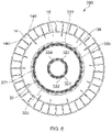
- the flow directing structures 322 may extend along the majority of the length of the turbine casing bleed manifold 32 d to form a plurality of turbine casing bleed manifold ducts circumferentially arranged around the turbine casing 34 and the diffuser casing 40 . This is illustrated in FIG. 6 , which illustrates a cross section through the same CHP component 200 as shown in FIGS. 2 to 5 across the diameter of the component (along section line C in FIG.
- FIG. 6 shows each of the flow directing structures 140 , 321 , 322 evenly distributed around the annulus form by the compressor outlet manifold 14 , the combustor casing bleed manifold 32 c and the turbine casing bleed manifold 32 d respectively, this is not essential and it will be appreciated that any distribution of flow directing structures 140 , 321 , 322 may be possible.
- the flow directing structures 140 , 321 , 322 can also provide mechanical support required for allowing other parts of the CHP component 200 to be formed on top of lower parts of the component when the component is made by additive manufacture.
- the holes 36 a may be formed into a grid of holes 36 a to evenly distribute the bleed gas around the internal circumference of the combustor 12 and along a portion of the length of the combustor 12 .
- FIG. 5 the holes 36 a may be formed into a grid of holes 36 a to evenly distribute the bleed gas around the internal circumference of the combustor 12 and along a portion of the length of the combustor 12 .
- the grid of holes 36 a may extend along the entire length of the combustor 12 , ensuring that the entire internal surface of the combustor casing 36 is cooled by the bleed gas, or could only extend along a portion of the combustor casing. This also ensures an even distribution of the bleed gas into the combustor 12 , which enhances mixing of the bleed gas, heated compressed gas and fuel, thus improving the combustion efficiency.
- the portion of bleed gas which flows through the turbine casing bleed manifold 32 d flows along the turbine casing 34 and the diffuser casing 40 and exits into the combustor casing bleed manifold 32 c as a position along the length of the combustor casing 36 .
- This portion of the bleed gas is then able to flow through the grid of holes 36 a into the combustor as described above.
- the turbine casing bleed manifold 32 d may join the combustor bleed manifold 32 c at a different location, for example at a portion of the combustor casing 36 corresponding to the turbine inlet manifold 16 or at the inlet to the combustor 12 from the recuperator 10 .
- the location that the turbine casing bleed manifold 32 d joins the combustor casing bleed manifold may be selected to ensure that substantially the same mass flow of bleed gas is achieved through each of the holes 36 a , thereby ensuring that no combustion gas passes from the combustor 12 into any of the bleed channels 32 .
- the bleed gas may be expelled upstream of the combustor 12 , for example into a manifold between the recuperator 10 and the combustor 12 , in order to mix the bleed gas with the heated compressed gas before entering the combustor 12 .
- the bleed gas could be expelled downstream of the combustor 12 , for example in the turbine inlet manifold 16 , in order to dilute the combustion gas prior to entering the turbine 8 in order to reduce the temperature of the gas entering the turbine.
- the hot gas flow (exhaust gas) generated in the combustor passes through the turbine inlet manifolds where it is guided by the nozzle guide vanes onto the blades of the turbine rotor (turbine wheel), driving the turbine and hence the shaft.
- the exhaust gas is expanded by the turbine and flows through the diffuser 21 to the aperture within the recuperator 10 .
- the ratio selector 30 is at least partially contained within the CHP component 200 , such as within the inner aperture 21 of the recuperator 10 .
- the ratio selector 30 entirely blocks the inlet 22 a to the bypass channel 22 , such that the fraction of the exhaust gas routed through the bypass channel 22 is zero, and all of the exhaust gas is routed through the recuperator channel 28 .
- the fraction of the exhaust gas routed through the recuperator channel 28 is 1, such that the ratio between the fraction of the exhaust gas routed through the recuperator channel 28 and the fraction of the exhaust gas routed through the bypass channel 22 is also 1 .
- This may be regarded as a power mode of the CHP system 2 , since all of the exhaust is routed through the recuperator channel, thereby increasing the heat transfer between the exhaust gas and the compressed gas in the recuperator 10 .
- the compressed gas entering the combustor 12 and the combustion gas entering the turbine 8 will therefore be at a higher temperature. This increases the efficiency thermal efficiency of the turbine 8 , which in turn increases the output at the load 24 coupled to the shaft 4 .
- some heating of the water in the heater 26 may also be provided, as the exhaust gas leaving the recuperator 10 is exhausted to the outside through the water heater 18 .
- the cold flow of compressed gas (high pressure or HP flow) is the same as in FIG. 7 .
- the ratio selector 30 is entirely contained outside the CHP component 200 , for example in abutment with an outer surface 201 of the CHP component 200 .
- the ratio selector 30 does not block the inlet 22 a to the bypass channel 22 , such that the fraction of the exhaust gas (low pressure or LP flow) routed through the bypass channel 22 is non-zero.
- the fraction of the exhaust gas routed through the recuperator channel 28 is also non-zero, such that the ratio between the fraction of the exhaust gas routed through the recuperator channel 28 and the fraction of the exhaust gas routed through the bypass channel 22 is greater than zero and less than one, for example 0.2, 0.5 or 0.8.
- the ratio between the fraction of the exhaust gas routed through the recuperator channel 28 and the fraction of the exhaust gas routed through the bypass channel 22 is dictated by parameters of the CHP component 200 , such as the ratio between the hydraulic diameter of the recuperator channel 28 and the hydraulic diameter of the bypass channel 22 or the ratio between the pressure drop across the recuperator 10 and the pressure drop across the bypass channel 22 .
- the ratio selector may operate in one or more intermediate positions between the first position and the second position in order to adjust the ratio between the first fraction of the exhaust gas routed through the recuperator channel and the second fraction of the exhaust gas routed through the bypass channel. This in turn alters the ratio of energy output by the component 200 which is converted into power in the shaft 4 , transferred to the load 24 , for example to be used generate electrical energy, and energy output by the component 200 converted into heat by the heater 26 .
- the ratio selector 30 may be movable between the first position, the second position and any intermediate positions by an actuator, such as a piston. The actuator may be controlled by a controller in order to selectively move the ratio selector 30 , and therefore selectively block a portion of the inlet 22 a to the annular bypass channel 22 during the operation of the CHP system 2 .
Landscapes
- Engineering & Computer Science (AREA)
- Chemical & Material Sciences (AREA)
- Combustion & Propulsion (AREA)
- Mechanical Engineering (AREA)
- General Engineering & Computer Science (AREA)
- Physics & Mathematics (AREA)
- Fluid Mechanics (AREA)
- Manufacturing & Machinery (AREA)
- Thermal Sciences (AREA)
- Materials Engineering (AREA)
- Life Sciences & Earth Sciences (AREA)
- High Energy & Nuclear Physics (AREA)
- Sustainable Development (AREA)
- Sustainable Energy (AREA)
- Air Supply (AREA)
- Heat-Exchange Devices With Radiators And Conduit Assemblies (AREA)
- Powder Metallurgy (AREA)
Abstract
Description
Claims (16)
Applications Claiming Priority (4)
| Application Number | Priority Date | Filing Date | Title |
|---|---|---|---|
| GB1806745.4A GB2573131A (en) | 2018-04-25 | 2018-04-25 | Combined heat and power system |
| GB1806745 | 2018-04-25 | ||
| GB1806745.4 | 2018-04-25 | ||
| PCT/GB2019/050371 WO2019207276A1 (en) | 2018-04-25 | 2019-02-12 | Combined heat and power system |
Publications (2)
| Publication Number | Publication Date |
|---|---|
| US20210156308A1 US20210156308A1 (en) | 2021-05-27 |
| US11560846B2 true US11560846B2 (en) | 2023-01-24 |
Family
ID=62236194
Family Applications (1)
| Application Number | Title | Priority Date | Filing Date |
|---|---|---|---|
| US17/045,857 Active 2039-04-19 US11560846B2 (en) | 2018-04-25 | 2019-02-12 | Combined heat and power system |
Country Status (7)
| Country | Link |
|---|---|
| US (1) | US11560846B2 (en) |
| EP (1) | EP3784889B1 (en) |
| JP (1) | JP7239609B2 (en) |
| CN (1) | CN111989471A (en) |
| CA (1) | CA3098018A1 (en) |
| GB (1) | GB2573131A (en) |
| WO (1) | WO2019207276A1 (en) |
Families Citing this family (19)
| Publication number | Priority date | Publication date | Assignee | Title |
|---|---|---|---|---|
| GB2573131A (en) * | 2018-04-25 | 2019-10-30 | Hieta Tech Limited | Combined heat and power system |
| US11378038B2 (en) | 2019-12-20 | 2022-07-05 | Raytheon Technologies Corporation | Axial expandable exhaust duct |
| US11453160B2 (en) | 2020-01-24 | 2022-09-27 | Hamilton Sundstrand Corporation | Method of building a heat exchanger |
| US11703283B2 (en) | 2020-01-24 | 2023-07-18 | Hamilton Sundstrand Corporation | Radial configuration for heat exchanger core |
| US11441850B2 (en) | 2020-01-24 | 2022-09-13 | Hamilton Sundstrand Corporation | Integral mounting arm for heat exchanger |
| US11460252B2 (en) * | 2020-01-24 | 2022-10-04 | Hamilton Sundstrand Corporation | Header arrangement for additively manufactured heat exchanger |
| US11686223B1 (en) | 2022-04-07 | 2023-06-27 | Sapphire Technologies, Inc. | Capturing and utilizing waste heat in electrical power generation |
| US12289034B2 (en) * | 2022-04-07 | 2025-04-29 | Sapphire Technologies, Inc. | Process integration in electrical power generation |
| US12104493B2 (en) | 2022-04-08 | 2024-10-01 | Sapphire Technologies, Inc. | Producing power with turboexpander generators based on specified output conditions |
| US12286953B2 (en) | 2022-07-25 | 2025-04-29 | Sapphire Technologies, Inc. | Energy recovery from a gas well |
| US12449195B2 (en) | 2022-07-25 | 2025-10-21 | Sapphire Technologies, Inc. | Conditioning gas for a pipeline |
| US12258887B2 (en) | 2022-07-25 | 2025-03-25 | Sapphire Technologies, Inc. | Cooling gas recovered from a well |
| US12374963B2 (en) | 2022-07-28 | 2025-07-29 | Sapphire Technologies, Inc. | Turboexpander system with low voltage ride through control architecture |
| DE102022207858A1 (en) * | 2022-07-29 | 2024-02-01 | Bhs Corrugated Maschinen- Und Anlagenbau Gmbh | Plant for producing corrugated cardboard and method for operating such a plant |
| US11795873B1 (en) | 2022-09-07 | 2023-10-24 | Sapphire Technologies, Inc. | Modular design of turboexpander components |
| EP4393825A1 (en) * | 2022-12-28 | 2024-07-03 | Airbus Operations, S.L.U. | Fuel conditioning system |
| CN116374214B (en) * | 2023-02-28 | 2025-09-16 | 中国电子科技集团公司第二十九研究所 | Split type annular gas-liquid heat exchange device and design method |
| US12065964B1 (en) * | 2023-04-18 | 2024-08-20 | Rtx Corporation | Bypass heat exchanger configuration to reroute core flow |
| FR3155030A1 (en) * | 2023-11-03 | 2025-05-09 | Safran Aircraft Engines | AIRCRAFT TURBOMACHINE |
Citations (27)
| Publication number | Priority date | Publication date | Assignee | Title |
|---|---|---|---|---|
| US3893300A (en) * | 1973-04-30 | 1975-07-08 | Nrg Inc | External combustion engine and engine cycle |
| GB2014662A (en) | 1978-02-16 | 1979-08-30 | English Electric Co Ltd | Gas Turbine Plant Providing Shaft Power and Heat |
| US5105617A (en) * | 1990-11-09 | 1992-04-21 | Tiernay Turbines | Cogeneration system with recuperated gas turbine engine |
| US5212942A (en) * | 1990-11-09 | 1993-05-25 | Tiernay Turbines, Inc. | Cogeneration system with recuperated gas turbine engine |
| US5855112A (en) * | 1995-09-08 | 1999-01-05 | Honda Giken Kogyo Kabushiki Kaisha | Gas turbine engine with recuperator |
| JP2001073799A (en) | 1999-09-06 | 2001-03-21 | Central Res Inst Of Electric Power Ind | Gas turbine for power generation and cogeneration system using the gas turbine |
| US6438936B1 (en) * | 2000-05-16 | 2002-08-27 | Elliott Energy Systems, Inc. | Recuperator for use with turbine/turbo-alternator |
| US6711889B2 (en) * | 2002-06-28 | 2004-03-30 | Industrial Technology Research Institute | Gas turbine engine |
| US20090193812A1 (en) | 2008-01-31 | 2009-08-06 | General Electric Company, A New York Corporation | Reheat Gas And Exhaust Gas Regenerator System For A Combined Cycle Power Plant |
| US7861510B1 (en) * | 2008-11-22 | 2011-01-04 | Florida Turbine Technologies, Inc. | Ceramic regenerator for a gas turbine engine |
| WO2013124053A1 (en) | 2012-02-21 | 2013-08-29 | Babcock Borsig Steinmüller Gmbh | Micro gas turbine system with a pipe-shaped recuperator |
| US20130236299A1 (en) * | 2012-03-06 | 2013-09-12 | Honeywell International Inc. | Tubular heat exchange systems |
| US20130318988A1 (en) | 2012-03-16 | 2013-12-05 | Mtu Aero Engines Gmbh | Aircraft engine with turbine heat exchanger bypass |
| US20140366547A1 (en) * | 2012-04-02 | 2014-12-18 | Powerphase, Llc | Gas turbine efficiency and regulation speed improvements using supplementary air system continuous and storage systems and methods of using the same |
| US20150128597A1 (en) * | 2013-11-12 | 2015-05-14 | Daniel Keith Schlak | Sky condenser with vertical tube compression and pressurized water utilization |
| US9118226B2 (en) * | 2012-10-12 | 2015-08-25 | Echogen Power Systems, Llc | Heat engine system with a supercritical working fluid and processes thereof |
| US20150240719A1 (en) * | 2012-04-02 | 2015-08-27 | Powerphase Llc | Gas turbine efficiency and regulation speed improvements using supplementary air system continuous and storage systems and methods of using the same |
| US20160010551A1 (en) * | 2014-07-08 | 2016-01-14 | 8 Rivers Capital, Llc | Method and system for power production wtih improved efficiency |
| US20170292450A1 (en) * | 2014-10-07 | 2017-10-12 | Dürr Systems Ag | Gas turbine arrangement |
| WO2017212211A1 (en) | 2016-06-09 | 2017-12-14 | Hieta Technologies Limited | Radial flow turbine heat engine |
| WO2018055325A1 (en) | 2016-09-23 | 2018-03-29 | Hieta Technologies Limited | Combustion chamber and heat exchanger |
| US20180094550A1 (en) * | 2015-06-01 | 2018-04-05 | William M. Conlon | Part load operation of liquid air power and storage system |
| US20180252158A1 (en) * | 2015-08-20 | 2018-09-06 | Aurelia Turbines Oy | System, method and computer program for operating a land- or marine-based multi-spool gas turbine |
| US20180313269A1 (en) * | 2017-04-26 | 2018-11-01 | Pratt & Whitney Canada Corp. | Apparatus and method for heating pre-combustor air in a gas turbine engine |
| US20190301749A1 (en) * | 2017-01-30 | 2019-10-03 | The Regents Of The University Of California | Storage-combined cold, heat and power |
| GB2573131A (en) * | 2018-04-25 | 2019-10-30 | Hieta Tech Limited | Combined heat and power system |
| US20210388730A1 (en) * | 2018-10-12 | 2021-12-16 | Bae Systems Plc | Compressor module |
Family Cites Families (4)
| Publication number | Priority date | Publication date | Assignee | Title |
|---|---|---|---|---|
| US6832470B2 (en) * | 2002-12-23 | 2004-12-21 | Elliott Energy Systems, Inc | Recuperator configuration |
| GB2399396A (en) * | 2003-03-13 | 2004-09-15 | Bowman Power Systems Ltd | Bypass valve for a recuperator |
| EP2019917A1 (en) * | 2006-05-02 | 2009-02-04 | Firebox Energy Systems Ltd. | Indirect-fired gas turbine power plant |
| JP2008291839A (en) * | 2007-05-10 | 2008-12-04 | Ebara Corp | Remote monitoring system and failure diagnostic method of micro-turbine cogeneration system |
-
2018
- 2018-04-25 GB GB1806745.4A patent/GB2573131A/en not_active Withdrawn
-
2019
- 2019-02-12 JP JP2020557190A patent/JP7239609B2/en active Active
- 2019-02-12 US US17/045,857 patent/US11560846B2/en active Active
- 2019-02-12 EP EP19705816.7A patent/EP3784889B1/en active Active
- 2019-02-12 WO PCT/GB2019/050371 patent/WO2019207276A1/en not_active Ceased
- 2019-02-12 CN CN201980026584.0A patent/CN111989471A/en active Pending
- 2019-02-12 CA CA3098018A patent/CA3098018A1/en not_active Abandoned
Patent Citations (29)
| Publication number | Priority date | Publication date | Assignee | Title |
|---|---|---|---|---|
| US3893300A (en) * | 1973-04-30 | 1975-07-08 | Nrg Inc | External combustion engine and engine cycle |
| GB2014662A (en) | 1978-02-16 | 1979-08-30 | English Electric Co Ltd | Gas Turbine Plant Providing Shaft Power and Heat |
| US5105617A (en) * | 1990-11-09 | 1992-04-21 | Tiernay Turbines | Cogeneration system with recuperated gas turbine engine |
| US5212942A (en) * | 1990-11-09 | 1993-05-25 | Tiernay Turbines, Inc. | Cogeneration system with recuperated gas turbine engine |
| US5855112A (en) * | 1995-09-08 | 1999-01-05 | Honda Giken Kogyo Kabushiki Kaisha | Gas turbine engine with recuperator |
| JP2001073799A (en) | 1999-09-06 | 2001-03-21 | Central Res Inst Of Electric Power Ind | Gas turbine for power generation and cogeneration system using the gas turbine |
| US6438936B1 (en) * | 2000-05-16 | 2002-08-27 | Elliott Energy Systems, Inc. | Recuperator for use with turbine/turbo-alternator |
| US6711889B2 (en) * | 2002-06-28 | 2004-03-30 | Industrial Technology Research Institute | Gas turbine engine |
| US20090193812A1 (en) | 2008-01-31 | 2009-08-06 | General Electric Company, A New York Corporation | Reheat Gas And Exhaust Gas Regenerator System For A Combined Cycle Power Plant |
| US7861510B1 (en) * | 2008-11-22 | 2011-01-04 | Florida Turbine Technologies, Inc. | Ceramic regenerator for a gas turbine engine |
| WO2013124053A1 (en) | 2012-02-21 | 2013-08-29 | Babcock Borsig Steinmüller Gmbh | Micro gas turbine system with a pipe-shaped recuperator |
| US20130236299A1 (en) * | 2012-03-06 | 2013-09-12 | Honeywell International Inc. | Tubular heat exchange systems |
| US20130318988A1 (en) | 2012-03-16 | 2013-12-05 | Mtu Aero Engines Gmbh | Aircraft engine with turbine heat exchanger bypass |
| US20140366547A1 (en) * | 2012-04-02 | 2014-12-18 | Powerphase, Llc | Gas turbine efficiency and regulation speed improvements using supplementary air system continuous and storage systems and methods of using the same |
| US20150240719A1 (en) * | 2012-04-02 | 2015-08-27 | Powerphase Llc | Gas turbine efficiency and regulation speed improvements using supplementary air system continuous and storage systems and methods of using the same |
| US9118226B2 (en) * | 2012-10-12 | 2015-08-25 | Echogen Power Systems, Llc | Heat engine system with a supercritical working fluid and processes thereof |
| US20150128597A1 (en) * | 2013-11-12 | 2015-05-14 | Daniel Keith Schlak | Sky condenser with vertical tube compression and pressurized water utilization |
| US20160010551A1 (en) * | 2014-07-08 | 2016-01-14 | 8 Rivers Capital, Llc | Method and system for power production wtih improved efficiency |
| US20170292450A1 (en) * | 2014-10-07 | 2017-10-12 | Dürr Systems Ag | Gas turbine arrangement |
| US20180094550A1 (en) * | 2015-06-01 | 2018-04-05 | William M. Conlon | Part load operation of liquid air power and storage system |
| US20180252158A1 (en) * | 2015-08-20 | 2018-09-06 | Aurelia Turbines Oy | System, method and computer program for operating a land- or marine-based multi-spool gas turbine |
| WO2017212211A1 (en) | 2016-06-09 | 2017-12-14 | Hieta Technologies Limited | Radial flow turbine heat engine |
| WO2018055325A1 (en) | 2016-09-23 | 2018-03-29 | Hieta Technologies Limited | Combustion chamber and heat exchanger |
| US20200025379A1 (en) * | 2016-09-23 | 2020-01-23 | Hieta Technologies Limited | Combustion chamber and heat exchanger |
| US20190301749A1 (en) * | 2017-01-30 | 2019-10-03 | The Regents Of The University Of California | Storage-combined cold, heat and power |
| US20180313269A1 (en) * | 2017-04-26 | 2018-11-01 | Pratt & Whitney Canada Corp. | Apparatus and method for heating pre-combustor air in a gas turbine engine |
| GB2573131A (en) * | 2018-04-25 | 2019-10-30 | Hieta Tech Limited | Combined heat and power system |
| US20210156308A1 (en) * | 2018-04-25 | 2021-05-27 | Hieta Technologies Limited | Combined heat and power system |
| US20210388730A1 (en) * | 2018-10-12 | 2021-12-16 | Bae Systems Plc | Compressor module |
Non-Patent Citations (2)
| Title |
|---|
| International Search Report and Written Opinion of the ISA for PCT/GB2019/050371, dated May 20, 2019, 14 pages. |
| Search Report for GB1806745.4, dated Oct. 23, 2018, 5 pages. |
Also Published As
| Publication number | Publication date |
|---|---|
| CA3098018A1 (en) | 2019-10-31 |
| CN111989471A (en) | 2020-11-24 |
| EP3784889A1 (en) | 2021-03-03 |
| GB2573131A (en) | 2019-10-30 |
| JP7239609B2 (en) | 2023-03-14 |
| JP2021522435A (en) | 2021-08-30 |
| GB201806745D0 (en) | 2018-06-06 |
| WO2019207276A1 (en) | 2019-10-31 |
| EP3784889B1 (en) | 2025-06-11 |
| US20210156308A1 (en) | 2021-05-27 |
Similar Documents
| Publication | Publication Date | Title |
|---|---|---|
| US11560846B2 (en) | Combined heat and power system | |
| KR102348770B1 (en) | Contoured wall heat exchanger | |
| CN114320599B (en) | Gas turbine engine, flow splitter thereof and method for manufacturing flow splitter | |
| US10753455B2 (en) | Additively manufactured gearbox with integral heat exchanger | |
| US11125160B2 (en) | Method and system for combination heat exchanger | |
| US10670349B2 (en) | Additively manufactured heat exchanger | |
| CN113374578B (en) | Frame for hot engine | |
| EP3516298B1 (en) | Combustion chamber and heat exchanger | |
| US20190024988A1 (en) | Header assembly for a heat exchanger | |
| US10746326B2 (en) | Additively manufactured tube array | |
| US20120201674A1 (en) | Cooling module design and method for cooling components of a gas turbine system | |
| US10495309B2 (en) | Surface contouring of a flowpath wall of a gas turbine engine | |
| US20190292984A1 (en) | Radial flow turbine heat engine | |
| US11885236B2 (en) | Airfoil tip rail and method of cooling |
Legal Events
| Date | Code | Title | Description |
|---|---|---|---|
| AS | Assignment |
Owner name: HIETA TECHNOLOGIES LIMITED, UNITED KINGDOM Free format text: ASSIGNMENT OF ASSIGNORS INTEREST;ASSIGNOR:JONES, SIMON LLOYD;REEL/FRAME:053998/0037 Effective date: 20201001 |
|
| FEPP | Fee payment procedure |
Free format text: ENTITY STATUS SET TO UNDISCOUNTED (ORIGINAL EVENT CODE: BIG.); ENTITY STATUS OF PATENT OWNER: LARGE ENTITY |
|
| STPP | Information on status: patent application and granting procedure in general |
Free format text: APPLICATION DISPATCHED FROM PREEXAM, NOT YET DOCKETED |
|
| STPP | Information on status: patent application and granting procedure in general |
Free format text: DOCKETED NEW CASE - READY FOR EXAMINATION |
|
| STPP | Information on status: patent application and granting procedure in general |
Free format text: NON FINAL ACTION MAILED |
|
| STPP | Information on status: patent application and granting procedure in general |
Free format text: RESPONSE TO NON-FINAL OFFICE ACTION ENTERED AND FORWARDED TO EXAMINER |
|
| STPP | Information on status: patent application and granting procedure in general |
Free format text: FINAL REJECTION MAILED |
|
| STPP | Information on status: patent application and granting procedure in general |
Free format text: RESPONSE AFTER FINAL ACTION FORWARDED TO EXAMINER |
|
| STPP | Information on status: patent application and granting procedure in general |
Free format text: NOTICE OF ALLOWANCE MAILED -- APPLICATION RECEIVED IN OFFICE OF PUBLICATIONS |
|
| STPP | Information on status: patent application and granting procedure in general |
Free format text: PUBLICATIONS -- ISSUE FEE PAYMENT VERIFIED |
|
| STCF | Information on status: patent grant |
Free format text: PATENTED CASE |
|
| AS | Assignment |
Owner name: HIETA TECHNOLOGIES LIMITED, UNITED KINGDOM Free format text: CHANGE OF ASSIGNEE ADDRESS;ASSIGNOR:HIETA TECHNOLOGIES LIMITED;REEL/FRAME:067477/0952 Effective date: 20240521 |