US11560220B2 - Sensor for monitoring rotors - Google Patents
Sensor for monitoring rotors Download PDFInfo
- Publication number
- US11560220B2 US11560220B2 US17/316,027 US202117316027A US11560220B2 US 11560220 B2 US11560220 B2 US 11560220B2 US 202117316027 A US202117316027 A US 202117316027A US 11560220 B2 US11560220 B2 US 11560220B2
- Authority
- US
- United States
- Prior art keywords
- rotating
- rotating tube
- sensors
- sensor mount
- tube
- Prior art date
- Legal status (The legal status is an assumption and is not a legal conclusion. Google has not performed a legal analysis and makes no representation as to the accuracy of the status listed.)
- Active, expires
Links
Images


Classifications
-
- B—PERFORMING OPERATIONS; TRANSPORTING
- B64—AIRCRAFT; AVIATION; COSMONAUTICS
- B64C—AEROPLANES; HELICOPTERS
- B64C27/00—Rotorcraft; Rotors peculiar thereto
- B64C27/006—Safety devices
-
- B—PERFORMING OPERATIONS; TRANSPORTING
- B64—AIRCRAFT; AVIATION; COSMONAUTICS
- B64C—AEROPLANES; HELICOPTERS
- B64C27/00—Rotorcraft; Rotors peculiar thereto
- B64C27/04—Helicopters
- B64C27/12—Rotor drives
-
- B—PERFORMING OPERATIONS; TRANSPORTING
- B64—AIRCRAFT; AVIATION; COSMONAUTICS
- B64C—AEROPLANES; HELICOPTERS
- B64C27/00—Rotorcraft; Rotors peculiar thereto
- B64C27/32—Rotors
-
- B—PERFORMING OPERATIONS; TRANSPORTING
- B64—AIRCRAFT; AVIATION; COSMONAUTICS
- B64C—AEROPLANES; HELICOPTERS
- B64C27/00—Rotorcraft; Rotors peculiar thereto
- B64C27/82—Rotorcraft; Rotors peculiar thereto characterised by the provision of an auxiliary rotor or fluid-jet device for counter-balancing lifting rotor torque or changing direction of rotorcraft
-
- G—PHYSICS
- G01—MEASURING; TESTING
- G01M—TESTING STATIC OR DYNAMIC BALANCE OF MACHINES OR STRUCTURES; TESTING OF STRUCTURES OR APPARATUS, NOT OTHERWISE PROVIDED FOR
- G01M13/00—Testing of machine parts
- G01M13/02—Gearings; Transmission mechanisms
- G01M13/028—Acoustic or vibration analysis
-
- G—PHYSICS
- G01—MEASURING; TESTING
- G01M—TESTING STATIC OR DYNAMIC BALANCE OF MACHINES OR STRUCTURES; TESTING OF STRUCTURES OR APPARATUS, NOT OTHERWISE PROVIDED FOR
- G01M13/00—Testing of machine parts
- G01M13/04—Bearings
- G01M13/045—Acoustic or vibration analysis
-
- B—PERFORMING OPERATIONS; TRANSPORTING
- B64—AIRCRAFT; AVIATION; COSMONAUTICS
- B64D—EQUIPMENT FOR FITTING IN OR TO AIRCRAFT; FLIGHT SUITS; PARACHUTES; ARRANGEMENTS OR MOUNTING OF POWER PLANTS OR PROPULSION TRANSMISSIONS IN AIRCRAFT
- B64D45/00—Aircraft indicators or protectors not otherwise provided for
- B64D2045/0085—Devices for aircraft health monitoring, e.g. monitoring flutter or vibration
Definitions
- the present invention relates in general to the field of rotorcraft, and more particularly to tail rotor sensors.
- tail rotor control faults are often detected using sensors mounted on the tail rotor gearbox, which is a long distance away from the tail rotor being monitored. These sensors usually detect problems in the tail rotor gearbox, which indirectly indicates a potential problem with the tail rotor. Accordingly, placing of a sensor proximate to the tail rotor is desirable.
- an apparatus comprises a rotating shaft coupled to a set of rotor blades, a non-rotating tube at least partially disposed within the rotating shaft and coupled to the rotating shaft, wherein the non-rotating tube comprises a first end and a second end, a sensor mount disposed within the non-rotating tube proximate to the second end of the non-rotating tube, and one or more sensors attached to the sensor mount, wherein the one or more sensors detect one or more parameters associated with the rotating shaft or the set of rotor blades.
- the one or more parameters comprise a vibration, a rotational speed, an acceleration, a temperature or a combination thereof; and the one or more sensors comprise a tachometer, a single axis accelerometer, a multiple axis accelerometer, a temperature sensor or a combination thereof.
- a Health and Usage Monitoring System (HUMS) is communicably coupled to the one or more sensors.
- one or more wires or cables, or a wireless transceiver are at least partially disposed within the non-rotating tube and coupled to the one or more sensors.
- an external sensor is attached to the sensor mount and positioned beyond the second end of the non-rotating tube.
- the sensor mount is cup-shaped and seals the second end of the non-rotating tube; and the sensor mount is attached to the non-rotating tube via an adhesive.
- the sensor mount includes a flange that mates with the second end of the non-rotating tube and controls a position of the sensor mount along the longitudinal axis of the non-rotating tube.
- a retention device affixes the sensor mount to the non-rotating tube, wherein the retention device comprises one or more cotter pins, a safety wire or a combination thereof.
- a set of bearings couples the non-rotating tube to the rotating shaft.
- a rotating standpipe is disposed between the rotating shaft and the non-rotating tube such that the non-rotating tube is coupled to the rotating standpipe and the rotating standpipe is coupled to the rotating shaft; and a control actuator is coupled proximate to the first end of the non-rotating tube, wherein the control actuator selectively moves the non-rotating tube along a longitudinal axis.
- the one or more sensors further detect a stickage and/or a slippage of the non-rotating tube.
- a clamp assembly is attached to an exterior of the non-rotating tube proximate to the second end of the non-rotating tube; a set of bearings couple the clamp assembly to the rotating standpipe; a crosshead is attached to an exterior of the rotating standpipe proximate to the set of bearings; a set of pitch link couple the set of rotor blades to the crosshead; and wherein the rotating standpipe is splined to the rotating shaft.
- at least one of the one or more sensors comprises an accelerometer; and the sensor mount and the accelerometer are positioned to create a vibration path between the set of bearings and the accelerometer.
- a method comprises providing a rotating shaft coupled to a set of rotor blades, a non-rotating tube at least partially disposed within the rotating shaft and coupled to the rotating shaft, wherein the non-rotating tube comprises a first end and a second end, a sensor mount disposed within the non-rotating tube proximate to the second end of the non-rotating tube, and one or more sensors attached to the sensor mount; and detecting one or more parameters associated with the rotating shaft or the set of rotor blades rotor using the one or more sensors.
- the one or more parameters comprise a vibration, a rotational speed, an acceleration, a temperature or a combination thereof; and the one or more sensors comprise a tachometer, a single axis accelerometer, a multiple axis accelerometer, a temperature sensor or a combination thereof.
- providing the one or more sensors comprises attaching the one or more sensors to the sensor mount; and providing the sensor mount comprises installing the sensor mount within the non-rotating tube proximate to the second end of the non-rotating tube.
- the method further comprises providing a set of bearings coupling the non-rotating tube to the rotating shaft.
- the method further comprises positioning an external sensor beyond the second end of the non-rotating tube and attaching the external sensor to the sensor mount.
- the method further comprises providing one or more wires or cables, or a wireless transceiver at least partially disposed within the non-rotating tube and coupled to the one or more sensors.
- the sensor mount is cup-shaped and seals the second end of the non-rotating tube; and the sensor mount is attached to the non-rotating tube via an adhesive.
- the method further comprises affixing the sensor mount to the non-rotating tube using a retention device, wherein the retention device comprises one or more cotter pins, a safety wire or a combination thereof.
- the method further comprises providing a rotating standpipe between the rotating shaft and the non-rotating tube such that the non-rotating tube is coupled to the rotating standpipe and the rotating standpipe is coupled to the rotating shaft; providing a control actuator coupled proximate to the first end of the non-rotating tube; and selectively moving the non-rotating tube along a longitudinal axis using the control actuator.
- the method further comprises detecting a stickage and/or a slippage of the non-rotating tube using the one or more sensors.
- the method further comprises providing a clamp assembly attached to an exterior of the non-rotating tube proximate to the second end of the non-rotating tube; providing a set of bearings coupling the clamp assembly to the rotating standpipe; providing a crosshead attached to an exterior of the rotating standpipe proximate to the set of bearings; providing a set of pitch link coupling the set of rotor blades to the crosshead; and wherein the rotating standpipe is splined to the rotating shaft.
- at least one of the one or more sensors comprises an accelerometer; and the retention device and the accelerometer are positioned to create a vibration path between the set of bearings and the accelerometer.
- a rotor assembly comprises: a gearbox; a set of rotor blades; a rotating shaft having a first end operably coupled to the gearbox and a second end operably coupled to the set of rotor blades; a rotating standpipe disposed at least partially within the rotating shaft and coupled to the rotating shaft; a non-rotating tube at least partially disposed within the rotating standpipe and coupled to the rotating standpipe, wherein the non-rotating tube comprises a first end extending through the gearbox, a second end extending beyond the second end of the rotating shaft, and a longitudinal axis; a sensor mount disposed within the non-rotating tube proximate to the second end of the non-rotating tube; one or more sensors attached to the sensor mount, wherein the one or more sensors detect one or more parameters associated with the rotating shaft, the rotating standpipe or the set of rotor blades; one or more wires or cables at least partially disposed within the non-rotating tube, wherein the one or more wires or cables
- FIG. 1 shows a perspective view of a helicopter in accordance with one embodiment of the present application
- FIG. 2 shows a partial cross-section, perspective view of a helicopter in accordance with one embodiment of the present application
- FIG. 3 shows a tail rotor assembly with the tail boom fuselage removed in accordance with one embodiment of the present invention
- FIG. 4 shows a cross-sectional view of a tail rotor pitch control assembly with one or more sensors in accordance with one embodiment of the present invention
- FIGS. 5 A and 5 B show the sensor mount 404 affixed to the non-rotating tube using various retention devices
- FIG. 6 illustrates the operation of the tail rotor pitch control assembly in accordance with one embodiment of the present invention.
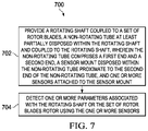
- FIG. 7 is a flowchart depicting a method for detecting one or more parameters associated with the rotating shaft or the set of rotor blades rotor using one or more sensors in accordance with one embodiment of the present invention.
- FIG. 1 shows perspective view of a helicopter 100 in accordance with one embodiment of the present application.
- helicopter 100 has a fuselage 102 and a rotor system 104 carried thereon.
- a plurality of rotor blades 106 is operably associated with a rotor system 104 for creating flight.
- a tail boom 108 is depicted that further includes tail rotor 110 .
- the present invention is not limited to helicopters and is applicable to other rotor propelled manned or unmanned aircraft including drones
- FIG. 2 shows a partial cross-section perspective view of helicopter 100 that includes additional detail of the present invention.
- Helicopter 100 further includes a rotor mast 112 , which is connected to the main rotor gearbox (MRGB) 114 .
- the MRGB 114 is connected to one or more accessory gear boxes 116 and one or more reduction gearboxes (RGB) 118 a , 118 b , hydraulic pump(s) and generator(s).
- RGB 118 a , 118 b is connected to one or more engines 120 a , 120 b , which are within an engine compartment 122 .
- a first tail rotor drive shaft 124 connects the MRGB 114 to an intermediate gearbox 126 and transmits mechanical rotation to the intermediate gearbox 126 .
- a second tail rotor drive shaft 128 connects the intermediate gearbox 126 to the tail rotor gearbox 130 and transmits mechanical rotation to the tail rotor gearbox 130 .
- the tail rotor gearbox 130 drives the tail rotor 110 .
- the intermediate gearbox 126 and the second tail rotor drive shaft 128 are not necessary.
- the first tail rotor drive shaft 124 and tail rotor gearbox 130 are not necessary when electrical power or hydraulic power is used to drive the tail rotor 110 .
- the sensor described herein is applicable to any tail rotor assembly regardless of how it is driven (i.e., mechanical, electrical, hydraulic, etc.) as long as the tail rotor assembly includes a non-rotating tube disposed within and coupled to the rotating shaft driving the tail rotor or a rotating standpipe coupled to the rotating shaft.
- the sensor is described with respect to mechanically driven tail rotor systems, but those skilled in the art will recognize that the sensor is not limited to any specific type of drive system or even to tail rotors.
- the following non-limiting example describes a tail rotor assembly that includes adjustable pitch blades, but the sensor described herein is also applicable to fixed pitch blades.
- FIG. 3 shows a tail rotor assembly 300 with the tail boom fuselage removed in accordance with one embodiment of the present invention.
- the tail rotor assembly 300 includes the tail rotor gearbox 130 mounted on the tail boom frame 302 .
- a rotating shaft or mast 304 has a first end 306 operably coupled to the tail rotor gearbox 130 and a second end 308 operably coupled to the set of rotor blades 312 .
- four rotor blades 312 are shown, other tail rotor assemblies may include as few as two or more than four rotor blades.
- a rotating standpipe 314 is disposed at least partially within the rotating shaft 304 and coupled to the rotating shaft 304 . Typically, the rotating standpipe 314 is splined to the rotating shaft 304 .
- a non-rotating tube 316 is at least partially disposed within the rotating standpipe 314 and coupled to the rotating standpipe 314 .
- the non-rotating tube 316 includes a first end 318 that extends through the tail rotor gearbox 130 , a second end 320 extending beyond the second end 308 of the rotating shaft 304 , and a longitudinal axis 322 .
- FIG. 4 shows a cross-sectional view of a tail rotor pitch control assembly 400 with one or more sensors 402 in accordance with one embodiment of the present invention.
- a sensor mount 404 is disposed within the non-rotating tube 316 proximate to the second end 320 of the non-rotating tube 316 .
- the one or more sensors 402 are attached to the sensor mount 404 within the non-rotating tube 316 .
- external sensor(s) may be attached to the sensor mount 404 and positioned beyond the second end 320 of the non-rotating tube 316 .
- the one or more sensors 402 detect one or more parameters associated with the rotating shaft 304 , the rotating standpipe 314 or the set of rotor blades 312 .
- the one or more parameters may include, but are not limited to, a vibration, a rotational speed, an acceleration, a temperature or a combination thereof.
- the one or more sensors 402 may include, but are not limited to, a tachometer, a single axis accelerometer, a multiple axis accelerometer, a temperature sensor or a combination thereof.
- the one or more sensors 402 can be communicably coupled to a Health and Usage Monitoring System (HUMS) or other computer/system.
- HUMS Health and Usage Monitoring System
- One or more wires or cables 406 are at least partially disposed within the non-rotating tube 316 and have a first end 408 extending through the first end 318 of the non-rotating tube 316 and a second end 410 coupled to the one or more sensors 402 .
- the first end 408 and/or second end 410 may include connectors, wiring harnesses or other forms of electrical or data connection.
- the one or more wires or cables 406 can be replaced with wireless transceivers or other devices to communicate sensor data to a control computer, HUMS, pilot or ground control.
- the sensor mount 404 is cup-shaped having a flange 412 , inner threads 414 and holes 416 .
- the flange 412 mates with the second end 320 of the non-rotating tube 316 and is used to control the position of the sensor mount along the longitudinal axis 322 of the non-rotating tube.
- the sensor mount 404 is attached or bonded to the non-rotating tube 316 with an adhesive and/or other types of fasteners (e.g., retention devices described below), and seals the second end 320 of the non-rotating tube 316 .
- the outer diameter of the sensor mount 404 fits inside the inner diameter of the non-rotating tube 316 . As shown in FIGS.
- the sensor mount 404 can also be affixed to the non-rotating tube 316 using a retention device, such as one or more cotter pins 502 , safety wire 504 or a combination thereof secured through the holes 416 of the sensor mount 404 .
- the retention device can be used in addition to the adhesive.
- a clamp assembly 418 is attached to an exterior of the non-rotating tube 316 proximate to the second end 320 of the non-rotating tube 316 .
- the clamp assembly 418 includes a spacer/bearing clamp 420 secured between a flange 422 on the non-rotating tube 316 and a non-rotating clamp nut 424 .
- a set of bearings 426 couples the clamp assembly 418 to the rotating standpipe 314 .
- a crosshead 428 is attached to an exterior of the rotating standpipe 314 proximate to the set of bearings 426 with a crosshead clamp plate 430 and crosshead attach bolts 432 .
- FIG. 6 illustrates the operation of the tail rotor pitch control assembly 400 in accordance with one embodiment of the present invention.
- a set of pitch links 602 couple the set of rotor blades 312 to the crosshead 428 .
- a control actuator 324 located on the other end of the tail rotor gearbox 130 is coupled to the first end 318 of the non-rotating tube 316 .
- the control actuator 324 adjusts a pitch of the set of rotor blades 312 and thus thrust by selectively moving the non-rotating tube 316 along the longitudinal axis 322 (inboard/outboard), which in turn moves the rotating standpipe 314 as indicated by arrow 604 .
- the one or more sensors 402 can be a single axis accelerometer that detects vibrations, which may indicate a component fault, in the set of bearings 426 or transmitted to the set of bearings 426 via a vibration path from the crosshead 428 , pitch links 602 or rotor blades 312 .
- the vibration path between the set of bearings and the one or more sensors 402 can be reduced or minimized by using an elongated sensor mount 404 to position the one or more sensors 402 closer to the area identified by the circle A.
- the one or more sensors 402 can be a two axis accelerometer that detects vibrations as described above and a stickage and/or a slippage of the non-rotating tube 316 .
- the present invention can be used with a rotor having fixed pitch blades by coupling the non-rotating tube 316 to the rotating shaft 304 instead of the rotating standpipe 314 .
- FIG. 7 is a flowchart depicting a method 700 for detecting one or more parameters associated with the rotating shaft or the set of rotor blades rotor using one or more sensors in accordance with one embodiment of the present invention.
- the method 700 includes providing a rotating shaft coupled to a set of rotor blades, a non-rotating tube at least partially disposed within the rotating shaft and coupled to the rotating shaft, wherein the non-rotating tube comprises a first end and a second end, a sensor mount disposed within the non-rotating tube proximate to the second end of the non-rotating tube, and one or more sensors attached to the sensor mount in block 702 .
- One or more parameters associated with the rotating shaft or the set of rotor blades rotor are detected using the one or more sensors in block 704 .
- the one or more parameters comprise a vibration, a rotational speed, an acceleration, a temperature or a combination thereof; and the one or more sensors comprise a tachometer, a single axis accelerometer, a multiple axis accelerometer, a temperature sensor or a combination thereof.
- providing the one or more sensors comprises attaching the one or more sensors to the sensor mount; and providing the sensor mount comprises installing the sensor mount within the non-rotating tube proximate to the second end of the non-rotating tube.
- the method further comprises providing a set of bearings coupling the non-rotating tube to the rotating shaft.
- the method further comprises positioning an external sensor beyond the second end of the non-rotating tube and attaching the external sensor to the sensor mount.
- the method further comprises providing one or more wires or cables, or a wireless transceiver at least partially disposed within the non-rotating tube and coupled to the one or more sensors.
- the sensor mount is cup-shaped and seals the second end of the non-rotating tube; and the sensor mount is attached to the non-rotating tube via an adhesive.
- the method further comprises affixing the sensor mount to the non-rotating tube using a retention device, wherein the retention device comprises one or more cotter pins, a safety wire or a combination thereof.
- the method further comprises providing a rotating standpipe between the rotating shaft and the non-rotating tube such that the non-rotating tube is coupled to the rotating standpipe and the rotating standpipe is coupled to the rotating shaft; providing a control actuator coupled proximate to the first end of the non-rotating tube; and selectively moving the non-rotating tube along a longitudinal axis using the control actuator.
- the method further comprises detecting a stickage and/or a slippage of the non-rotating tube using the one or more sensors.
- the method further comprises providing a clamp assembly attached to an exterior of the non-rotating tube proximate to the second end of the non-rotating tube; providing a set of bearings coupling the clamp assembly to the rotating standpipe; providing a crosshead attached to an exterior of the rotating standpipe proximate to the set of bearings; providing a set of pitch link coupling the set of rotor blades to the crosshead; and wherein the rotating standpipe is splined to the rotating shaft.
- at least one of the one or more sensors comprises an accelerometer; and the retention device and the accelerometer are positioned to create a vibration path between the set of bearings and the accelerometer.
- the words “comprising” (and any form of comprising, such as “comprise” and “comprises”), “having” (and any form of having, such as “have” and “has”), “including” (and any form of including, such as “includes” and “include”) or “containing” (and any form of containing, such as “contains” and “contain”) are inclusive or open-ended and do not exclude additional, unrecited elements or method steps.
- compositions and methods comprising or may be replaced with “consisting essentially of” or “consisting of.”
- the phrase “consisting essentially of” requires the specified integer(s) or steps as well as those that do not materially affect the character or function of the claimed invention.
- the term “consisting” is used to indicate the presence of the recited integer (e.g., a feature, an element, a characteristic, a property, a method/process step, or a limitation) or group of integers (e.g., feature(s), element(s), characteristic(s), property(ies), method/process(s) steps, or limitation(s)) only.
- A, B, C, or combinations thereof refers to all permutations and combinations of the listed items preceding the term.
- “A, B, C, or combinations thereof” is intended to include at least one of: A, B, C, AB, AC, BC, or ABC, and if order is important in a particular context, also BA, CA, CB, CBA, BCA, ACB, BAC, or CAB.
- expressly included are combinations that contain repeats of one or more item or term, such as BB, AAA, AB, BBC, AAABCCCC, CBBAAA, CABABB, and so forth.
- BB BB
- AAA AAA
- AB BBC
- AAABCCCCCC CBBAAA
- CABABB CABABB
- words of approximation such as, without limitation, “about,” “substantial” or “substantially” refers to a condition that when so modified is understood to not necessarily be absolute or perfect but would be considered close enough to those of ordinary skill in the art to warrant designating the condition as being present. The extent to which the description may vary will depend on how great a change can be instituted and still have one of ordinary skill in the art recognize the modified feature as still having the required characteristics and capabilities of the unmodified feature. In general, but subject to the preceding discussion, a numerical value herein that is modified by a word of approximation such as “about” may vary from the stated value by at least ⁇ 1, 2, 3, 4, 5, 6, 7, 10, 12 or 15%.
- the methods may include more, fewer, or other steps. Additionally, steps may be performed in any suitable order.
Abstract
Description
Claims (35)
Priority Applications (1)
| Application Number | Priority Date | Filing Date | Title |
|---|---|---|---|
| US17/316,027 US11560220B2 (en) | 2018-11-16 | 2021-05-10 | Sensor for monitoring rotors |
Applications Claiming Priority (2)
| Application Number | Priority Date | Filing Date | Title |
|---|---|---|---|
| US16/192,901 US11034438B2 (en) | 2018-11-16 | 2018-11-16 | Sensor for monitoring rotors |
| US17/316,027 US11560220B2 (en) | 2018-11-16 | 2021-05-10 | Sensor for monitoring rotors |
Related Parent Applications (1)
| Application Number | Title | Priority Date | Filing Date |
|---|---|---|---|
| US16/192,901 Continuation US11034438B2 (en) | 2018-11-16 | 2018-11-16 | Sensor for monitoring rotors |
Publications (2)
| Publication Number | Publication Date |
|---|---|
| US20210309349A1 US20210309349A1 (en) | 2021-10-07 |
| US11560220B2 true US11560220B2 (en) | 2023-01-24 |
Family
ID=65243318
Family Applications (2)
| Application Number | Title | Priority Date | Filing Date |
|---|---|---|---|
| US16/192,901 Active 2039-11-26 US11034438B2 (en) | 2018-11-16 | 2018-11-16 | Sensor for monitoring rotors |
| US17/316,027 Active 2039-02-20 US11560220B2 (en) | 2018-11-16 | 2021-05-10 | Sensor for monitoring rotors |
Family Applications Before (1)
| Application Number | Title | Priority Date | Filing Date |
|---|---|---|---|
| US16/192,901 Active 2039-11-26 US11034438B2 (en) | 2018-11-16 | 2018-11-16 | Sensor for monitoring rotors |
Country Status (2)
| Country | Link |
|---|---|
| US (2) | US11034438B2 (en) |
| EP (1) | EP3653496B1 (en) |
Families Citing this family (2)
| Publication number | Priority date | Publication date | Assignee | Title |
|---|---|---|---|---|
| US11034438B2 (en) | 2018-11-16 | 2021-06-15 | Textron Innovations Inc. | Sensor for monitoring rotors |
| US11964754B2 (en) * | 2021-12-22 | 2024-04-23 | Lockheed Martin Corporation | Bearing assembly |
Citations (14)
| Publication number | Priority date | Publication date | Assignee | Title |
|---|---|---|---|---|
| US4379678A (en) | 1980-10-07 | 1983-04-12 | Textron, Inc. | Individual blade control |
| US20100116925A1 (en) | 2006-02-16 | 2010-05-13 | Tuvia Segal | Stabilization for flight platforms |
| US8123177B2 (en) * | 2008-05-14 | 2012-02-28 | Diehl Aerospace Gmbh | Input system for a landing flap control of an aircraft |
| EP2433866A2 (en) | 2010-09-28 | 2012-03-28 | Simmonds Precision Products, Inc. | Wireless rotor track and balance system for rotorcraft |
| EP2664545A1 (en) | 2012-05-16 | 2013-11-20 | Eurocopter | Device for supplying electric power to at least one device of an aircraft rotor and aircraft |
| US20140312722A1 (en) | 2013-04-18 | 2014-10-23 | Oeco, Llc | Mast-mounted aircraft generator |
| US20160200430A1 (en) | 2014-05-23 | 2016-07-14 | Bell Helicopter Textron Inc. | Tail Rotor Actuation System |
| WO2016137536A1 (en) | 2014-10-21 | 2016-09-01 | Sikorsky Aircraft Corporation | Compressive wireless sensing for rotor loads and motion |
| US9701420B1 (en) | 2016-05-09 | 2017-07-11 | Bell Helicopter Textron Inc. | Task-based health data monitoring of aircraft components |
| US10094138B2 (en) * | 2016-12-29 | 2018-10-09 | Shadecraft, Inc. | Control of multiple intelligent umbrellas and/or robotic shading systems |
| US10577078B2 (en) * | 2017-04-24 | 2020-03-03 | General Electric Company | Systems and methods for electronic measurement of propeller blade angle |
| US10612987B2 (en) * | 2018-06-05 | 2020-04-07 | Textron Innovations Inc. | System for monitoring characteristics of a load-bearing rotating shaft |
| US20200156774A1 (en) | 2018-11-16 | 2020-05-21 | Bell Helicopter Textron Inc. | Sensor for monitoring rotors |
| US20200247529A1 (en) * | 2017-01-30 | 2020-08-06 | Ge Avio S.R.L. | System and method of locating feathering propeller blade angular position |
-
2018
- 2018-11-16 US US16/192,901 patent/US11034438B2/en active Active
-
2019
- 2019-01-23 EP EP19153234.0A patent/EP3653496B1/en active Active
-
2021
- 2021-05-10 US US17/316,027 patent/US11560220B2/en active Active
Patent Citations (15)
| Publication number | Priority date | Publication date | Assignee | Title |
|---|---|---|---|---|
| US4379678A (en) | 1980-10-07 | 1983-04-12 | Textron, Inc. | Individual blade control |
| US20100116925A1 (en) | 2006-02-16 | 2010-05-13 | Tuvia Segal | Stabilization for flight platforms |
| US8123177B2 (en) * | 2008-05-14 | 2012-02-28 | Diehl Aerospace Gmbh | Input system for a landing flap control of an aircraft |
| EP2433866A2 (en) | 2010-09-28 | 2012-03-28 | Simmonds Precision Products, Inc. | Wireless rotor track and balance system for rotorcraft |
| EP2664545A1 (en) | 2012-05-16 | 2013-11-20 | Eurocopter | Device for supplying electric power to at least one device of an aircraft rotor and aircraft |
| US20140312722A1 (en) | 2013-04-18 | 2014-10-23 | Oeco, Llc | Mast-mounted aircraft generator |
| US20160200430A1 (en) | 2014-05-23 | 2016-07-14 | Bell Helicopter Textron Inc. | Tail Rotor Actuation System |
| US10023304B2 (en) | 2014-05-23 | 2018-07-17 | Bell Helicopter Textron Inc. | Tail rotor actuation system |
| WO2016137536A1 (en) | 2014-10-21 | 2016-09-01 | Sikorsky Aircraft Corporation | Compressive wireless sensing for rotor loads and motion |
| US9701420B1 (en) | 2016-05-09 | 2017-07-11 | Bell Helicopter Textron Inc. | Task-based health data monitoring of aircraft components |
| US10094138B2 (en) * | 2016-12-29 | 2018-10-09 | Shadecraft, Inc. | Control of multiple intelligent umbrellas and/or robotic shading systems |
| US20200247529A1 (en) * | 2017-01-30 | 2020-08-06 | Ge Avio S.R.L. | System and method of locating feathering propeller blade angular position |
| US10577078B2 (en) * | 2017-04-24 | 2020-03-03 | General Electric Company | Systems and methods for electronic measurement of propeller blade angle |
| US10612987B2 (en) * | 2018-06-05 | 2020-04-07 | Textron Innovations Inc. | System for monitoring characteristics of a load-bearing rotating shaft |
| US20200156774A1 (en) | 2018-11-16 | 2020-05-21 | Bell Helicopter Textron Inc. | Sensor for monitoring rotors |
Non-Patent Citations (3)
| Title |
|---|
| European Patent Office, Communication pursuant to Article 94(3) EPC for EP Application No. 19153234.0 dated Dec. 2, 2019, 6 pp. |
| European Patent Office, European Search Report for EP Appl. No. 19153234.0 dated Jun. 13, 2019, 6 pp. |
| Rule, et al. "Experimental Installation of Mast Mounted Sight on an OH-58C Helicopter" Nov. 3, 1980, XP055588798, URL:https://apps.dtic.mil/dtic/tr/fulltext/u2/a091074.pdf, 82 pp. |
Also Published As
| Publication number | Publication date |
|---|---|
| EP3653496B1 (en) | 2020-09-23 |
| US11034438B2 (en) | 2021-06-15 |
| US20200156774A1 (en) | 2020-05-21 |
| EP3653496A1 (en) | 2020-05-20 |
| US20210309349A1 (en) | 2021-10-07 |
Similar Documents
| Publication | Publication Date | Title |
|---|---|---|
| US11560220B2 (en) | Sensor for monitoring rotors | |
| US8403643B2 (en) | Dual frequency hub mounted vibration suppressor system | |
| US10279901B2 (en) | Rotating proprotor arrangement for a tiltrotor aircraft | |
| US20170225774A1 (en) | Anti-vibration load generating aircraft actuation system | |
| US10385959B2 (en) | Flange-mounted ring gear for improved heat management | |
| US20160207620A1 (en) | Rotor hub for rotary wing aircraft | |
| EP3437992B1 (en) | Rotor span-balance pocket | |
| EP3177525B1 (en) | Flex beam for rotor assembly | |
| US9725166B2 (en) | Counter-rotating rotor system with static mast | |
| EP3299285A1 (en) | Active thermal management for fire-tolerant drive systems | |
| US11643197B2 (en) | Reduced height swashplate assembly | |
| EP3539868B1 (en) | Flexible coupling for standpipe assembly | |
| US10823289B2 (en) | Floating ducts | |
| US10981647B2 (en) | Rotor span-balance pocket | |
| EP3299676A1 (en) | Flange-mounted ring gear for improved heat management | |
| US20190241258A1 (en) | Rotor blade deflection sensing system | |
| US11541995B2 (en) | Rotor blade assembly for bearingless rotor | |
| EP2123555A2 (en) | Directional control arrangement to provide stabilizing feedback to a structural bending mode | |
| US11753156B2 (en) | Main rotor blade using integral metallic center block strap assembly | |
| US11433996B2 (en) | Lightweight low drag rotor pitch beam | |
| WO2015200757A1 (en) | Flex beam clamp for rotor assembly | |
| US10703472B2 (en) | Directional control for coaxial rotary wing craft | |
| US20200122826A1 (en) | Passive Hub Flapping Lock |
Legal Events
| Date | Code | Title | Description |
|---|---|---|---|
| FEPP | Fee payment procedure |
Free format text: ENTITY STATUS SET TO UNDISCOUNTED (ORIGINAL EVENT CODE: BIG.); ENTITY STATUS OF PATENT OWNER: LARGE ENTITY |
|
| AS | Assignment |
Owner name: BELL TEXTRON INC., TEXAS Free format text: CERTIFICATE OF AMENDMENT;ASSIGNOR:BELL HELICOPTER TEXTRON INC.;REEL/FRAME:056613/0506 Effective date: 20190701 Owner name: BELL HELICOPTER TEXTRON INC., UNITED STATES Free format text: ASSIGNMENT OF ASSIGNORS INTEREST;ASSIGNORS:TUCKER, BRIAN EDWARD;SHIMEK, GLENN ALAN;JONES, LEONARD N.;REEL/FRAME:056571/0590 Effective date: 20181115 Owner name: BELL HELICOPTER TEXTRON INC., TEXAS Free format text: ASSIGNMENT OF ASSIGNORS INTEREST;ASSIGNOR:WENDELSDORF, JOSEPH;REEL/FRAME:056571/0488 Effective date: 19740903 |
|
| STPP | Information on status: patent application and granting procedure in general |
Free format text: DOCKETED NEW CASE - READY FOR EXAMINATION |
|
| AS | Assignment |
Owner name: TEXTRON INNOVATIONS INC., RHODE ISLAND Free format text: ASSIGNMENT OF ASSIGNORS INTEREST;ASSIGNOR:BELL TEXTRON INC.;REEL/FRAME:058987/0447 Effective date: 20220102 |
|
| STPP | Information on status: patent application and granting procedure in general |
Free format text: AWAITING TC RESP., ISSUE FEE NOT PAID |
|
| STPP | Information on status: patent application and granting procedure in general |
Free format text: NOTICE OF ALLOWANCE MAILED -- APPLICATION RECEIVED IN OFFICE OF PUBLICATIONS |
|
| STPP | Information on status: patent application and granting procedure in general |
Free format text: PUBLICATIONS -- ISSUE FEE PAYMENT VERIFIED |
|
| STCF | Information on status: patent grant |
Free format text: PATENTED CASE |