US1155291A - Starting-box. - Google Patents
Starting-box. Download PDFInfo
- Publication number
- US1155291A US1155291A US85067614A US1914850676A US1155291A US 1155291 A US1155291 A US 1155291A US 85067614 A US85067614 A US 85067614A US 1914850676 A US1914850676 A US 1914850676A US 1155291 A US1155291 A US 1155291A
- Authority
- US
- United States
- Prior art keywords
- lever
- arm
- box
- spring
- starting
- Prior art date
- Legal status (The legal status is an assumption and is not a legal conclusion. Google has not performed a legal analysis and makes no representation as to the accuracy of the status listed.)
- Expired - Lifetime
Links
- 239000011435 rock Substances 0.000 description 8
- 238000010276 construction Methods 0.000 description 3
- 230000004048 modification Effects 0.000 description 3
- 238000012986 modification Methods 0.000 description 3
- 101100497221 Bacillus thuringiensis subsp. alesti cry1Ae gene Proteins 0.000 description 1
- 239000012634 fragment Substances 0.000 description 1
- 230000000452 restraining effect Effects 0.000 description 1
Images

Classifications
-
- H—ELECTRICITY
- H01—ELECTRIC ELEMENTS
- H01H—ELECTRIC SWITCHES; RELAYS; SELECTORS; EMERGENCY PROTECTIVE DEVICES
- H01H19/00—Switches operated by an operating part which is rotatable about a longitudinal axis thereof and which is acted upon directly by a solid body external to the switch, e.g. by a hand
- H01H19/54—Switches operated by an operating part which is rotatable about a longitudinal axis thereof and which is acted upon directly by a solid body external to the switch, e.g. by a hand the operating part having at least five or an unspecified number of operative positions
- H01H19/60—Angularly-movable actuating part carrying no contacts
- H01H19/62—Contacts actuated by radial cams
Definitions
- MAX TAIGMAN OF NEW YORK, N. Y.
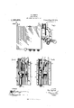
- Neuron- Figure 1 is a front view of a starting box having an attachment constructed and arranged in accordance with the present invention
- Fig. 2 is an end view of a starting box, showing the attachment in normal inactive relation to the switch levei ⁇ ofsaid box
- Fig. 3 shows the same, the attachment being shown in active position
- Fig. i is a side view of a box, showing an attachment applied thereto, said attachment being constructed and arranged in accordance with a modification of the invention
- Fig. 5 is a horizontal section taken on the line 5-5 in Fig. 4
- Fig. 6 is an end view of a starting box, showing a modified form of the attachment
- Fig. 7 is a detail yiew, show* ing a fragment of a modified form of the attachment shown in Fig. 6, the view being taken from the position indicated by the arrow (7
- Fig. 8 is a top view of the latch employed in the modified formseen in Figs. 6 and 7, the view being taken from the position -indicated by the arrow (8).
- a latch arm 15 is pivotally mounted on one of the bracket hangers 16, a screw bolt 17 being employed for that purpose.
- a hook 18 is formed, being extended laterally from the arm 15 to pass under, in the path of the outer end of, a switch lever 19, as shown best in Fig. 3 of the drawings.
- the arm 15 is moved to the position shown in Fig. 3 of the drawings by a spring 20, which extends between and bears upon the Specification of Letters Patent.
- the foot 21 supports at the rear edge thereof, a pin 22, by which the spring 20-is guided.
- the body 23)y from which the arm 15 and the foot 21 are extended, is further provided with a bracket arm 21, perforated to receive the hooked end of a spring 25, the lower end of which spring normally engages a hook 26 formed on the lever 19.
- the spring 25 has strength su'liicient to lift the outer end o f the lever 19 to its normal or inactive p0- sition, and to overcome the pressure of the spring 20.
- the power exerted by said spring 25 operates at all times to maintain the arm l5 in the position best shown in Fig. 2 of the drawings.
- the backward swing of the arm 15 is arrested and held in position by the pin 22, which normally bears against the under side of the hanger 16 to which the attachment is pivoted.
- a foot-treadle mechanism is usually operatively connected with the lever 19.
- the operator manipulates the treadle to start the motor for which the starting box is provided. If the spring 25 does break or develop itsinactive condition, it is when the outer end of the lever 19 is forced down. This is the position to which said lever is moved to deliver cur-- rent through said box to said motor. Though the operator may not be aware of the breaking of the spring 25, nevertheless, in order to stop the motor it is necessary to move the lever 19 to the position where the outer end of the same is lifted. It is then that the spring 20 rocks the arm 15 to insert the head 18 thereof into the path of said lever, to hold the same immovable thereafter.
- a modiied form of the invention is shown the modification consisting in employing clamping jaws 27 and 28. These jaws are arranged to pass around the extension body 29 of the hangers 16.
- the jaws 27 and 28 are drawn tightly to service position by means of a screw bolt 30 and a nut 31 with which the same is equipped.
- the clamping jaws 27 and 2S are employed only where the hanger 1G is not provided with the outward flange 3Q, and where convenient means is not afforded to secure the bolt 33 which forms the pivot for the arm 15 and the body 23 thereof.
- the jaw 9.7 has an angular bracket extension 34, one oif the bends whereo'f is disposed parallel with the side ofthe box to which the attachment is applied.
- rllhe modification shown in Figs. G, 7 and 8 consists in employing a counter-weight 35, which is substituted for the spring 20,
- the pin 22 operates as ay stop member for the backward swing of the arm 15, to regulate the working position of the spring 25. Then the spring 25 becomes broken or relaxed, the coun'terweight 35 overbalances the structure, and rocks the arm 15 to place the hook 18 in the path of the lever 19.
- This form of the invention Oilersy many advantages over the other forms, one of which is its simplicity of construction, the arm 15, body 23, hook 18, counterweight 35 and pin 22 being integrally cast or formed.
- a starting box embodying a pivoted switch lever, said lever being movable to oil position; a latch arm pivotally mounted adjacent said lever for engaging the same when at said oil positionv when unrestrained; and power means operatively connecting said latch' arm and said lever, for normally supporting said lever and arm and for restraining saidarm from engaging said lever.
- a starting box a pivoted switch lever, a portion of said lever being within said box, and a portion of sa'id lever extending outside of said box; a latch arm pivotalliy mounted' on said box for engaging said lever when unrestrained; said arm having a hook at one end thereof and a bracket arm at theother end thereof; a spring operatively connecting said lever and said bracket arm to rock said latch a'rm to a position where said h'o'ok is removed from the path of said lever; and means operatively connected with said latch' arm for rocking the same to dispose the hook in the path of said lever.
- a starting box a pivoted switch lever, a portion of said' lever being within said box, and a portion oil said lever extending outside of said box; a latch arm pivota'lly mounted on said box for engaging said lever when unrestrained; said arm having a hook at one end thereof and a bracket arm at vthe other end thereof; a' con.- necting spring operatively connecting sa'id lever and said bracket arm to rock said latch arm to a position where said hook is removed from the path of said lever; and' an auxiliary spring operatively engaging sa'id' latch armto' rock the same, for d'isprsing the hook at the endI thereof in the path of said lever when said' connecting( spring fails to support said lever.
Landscapes
- Holders For Apparel And Elements Relating To Apparel (AREA)
Description
MMMMMMMM N.
TTTTTTTTTT X.
APPLICAT LY I3, I9l4. 1,155,291. Patented sept. 2s, 1915.
/6 2 EEEEEEEEEEEE l.
H1, f1 MHH I M. TAIGMAN.
STARTING BOX.
APPupATloN FILED 1uLY la. 1914.
1 1 55,29 1 Patented Sept. 28, 1915.
2 SHEETS-SHEET 2. Ts :1.41 Tags.
.mln-fg@ www H11 i l/v l/E/v TUR Mar Eyman A TTOHNEYS AAAAAAAAAAAAAAAAAAAAAAAAAAAAAAAAAAA c.
UNITED STATES PATENT GFFICE.
MAX TAIGMAN, OF NEW YORK, N. Y.
STARTING-BOX.
Application filed July 13, 1914.
To all whom t may concern.:
Be it known that I, MAX TAIGMAN, a citizen of the United States, and a resident of the city of New York, borough of Manhattan, in the county and State of New York,
have invented a new and Improved Starttive; and to provide an attachment which may be mounted on starting boxes already in service.
.Neumann-Figure 1 is a front view of a starting box having an attachment constructed and arranged in accordance with the present invention; Fig. 2 is an end view of a starting box, showing the attachment in normal inactive relation to the switch levei` ofsaid box; Fig. 3 shows the same, the attachment being shown in active position;
Fig. i is a side view of a box, showing an attachment applied thereto, said attachment being constructed and arranged in accordance with a modification of the invention; Fig. 5 is a horizontal section taken on the line 5-5 in Fig. 4; Fig. 6 is an end view of a starting box, showing a modified form of the attachment; Fig. 7 is a detail yiew, show* ing a fragment of a modified form of the attachment shown in Fig. 6, the view being taken from the position indicated by the arrow (7 Fig. 8 is a top view of the latch employed in the modified formseen in Figs. 6 and 7, the view being taken from the position -indicated by the arrow (8).
Description-As seen in the drawings, and particularly Figs. 1 to 3 thereof, wherein is shown the preferred form of the invention, a latch arm 15 is pivotally mounted on one of the bracket hangers 16, a screw bolt 17 being employed for that purpose. At the lower end of the latch arm 15, a hook 18 is formed, being extended laterally from the arm 15 to pass under, in the path of the outer end of, a switch lever 19, as shown best in Fig. 3 of the drawings.
The arm 15 is moved to the position shown in Fig. 3 of the drawings by a spring 20, which extends between and bears upon the Specification of Letters Patent.
Patented sept. 28, 1915.
Serial No. 850,676.
The body 23)y from which the arm 15 and the foot 21 are extended, is further provided with a bracket arm 21, perforated to receive the hooked end of a spring 25, the lower end of which spring normally engages a hook 26 formed on the lever 19. The spring 25 has strength su'liicient to lift the outer end o f the lever 19 to its normal or inactive p0- sition, and to overcome the pressure of the spring 20. The power exerted by said spring 25 operates at all times to maintain the arm l5 in the position best shown in Fig. 2 of the drawings. The backward swing of the arm 15 is arrested and held in position by the pin 22, which normally bears against the under side of the hanger 16 to which the attachment is pivoted.
lVhen the spring 25 is broken or becomes so relaxed as not to lift the lever 19 to its inactive position, the spring 20 rocks the latch arm 15 to the position substantially as shown in Fig. 8 of the drawings, where it extends below and prevents the depression of the lever 19, thereby notifying the operator of the fact that the spring 25 is not in good operating condition.
It will be understood that when operating starting boxes thus equipped, a foot-treadle mechanism is usually operatively connected with the lever 19. The operator manipulates the treadle to start the motor for which the starting box is provided. Ifthe spring 25 does break or develop itsinactive condition, it is whenthe outer end of the lever 19 is forced down. This is the position to which said lever is moved to deliver cur-- rent through said box to said motor. Though the operator may not be aware of the breaking of the spring 25, nevertheless, in order to stop the motor it is necessary to move the lever 19 to the position where the outer end of the same is lifted. It is then that the spring 20 rocks the arm 15 to insert the head 18 thereof into the path of said lever, to hold the same immovable thereafter.
In Figs. 4 and 5 of the drawings, a modiied form of the invention is shown the modification consisting in employing clamping jaws 27 and 28. These jaws are arranged to pass around the extension body 29 of the hangers 16. The jaws 27 and 28 are drawn tightly to service position by means of a screw bolt 30 and a nut 31 with which the same is equipped. The clamping jaws 27 and 2S are employed only where the hanger 1G is not provided with the outward flange 3Q, and where convenient means is not afforded to secure the bolt 33 which forms the pivot for the arm 15 and the body 23 thereof. To furnish the required support for the pivot bolt 33, the jaw 9.7 has an angular bracket extension 34, one oif the bends whereo'f is disposed parallel with the side ofthe box to which the attachment is applied.
rllhe modification shown in Figs. G, 7 and 8 consists in employing a counter-weight 35, which is substituted for the spring 20, In this form of the construction, the pin 22 operates as ay stop member for the backward swing of the arm 15, to regulate the working position of the spring 25. Then the spring 25 becomes broken or relaxed, the coun'terweight 35 overbalances the structure, and rocks the arm 15 to place the hook 18 in the path of the lever 19. This form of the invention Oilersy many advantages over the other forms, one of which is its simplicity of construction, the arm 15, body 23, hook 18, counterweight 35 and pin 22 being integrally cast or formed. Y
In all of the forms of the construction it isto be seen that when the spring 25 upon which the correct operation of the starting box depend's, breaks or becomes relaxed, the counterbalancing springs or weights with whichf the arnr 15 is'equipped, rock said arm and the hook 18 thereof into a position to engage and; support the outer -endl of the lever 19".
Claims:
1,. A starting box embodying a pivoted switch lever, said lever being movable to oil position; a latch arm pivotally mounted adjacent said lever for engaging the same when at said oil positionv when unrestrained; and power means operatively connecting said latch' arm and said lever, for normally supporting said lever and arm and for restraining saidarm from engaging said lever.
2. In combination, a starting box; a pivotedv switch lever, a portion of sai-d lever Copies of this patent may be btained foi` ve' cents each, by addressing the Commissidner of Patenti.'
being within said box, and a. portion of said lever extending outside ol said box; a latch arm pivotally mounted on said box lior engaging said lever when unrestrained; said arm having a hook at one end thereo'l and a bracket arin at the other end thereof; and a spring operatively connecting said lever and said bracket arm to rock said latch arm to a position where said hook is removed from the. path of said lever.
8. In combination, a starting box; a pivoted switch lever, a portion of said lever being within said box, and a portion of sa'id lever extending outside of said box; a latch arm pivotalliy mounted' on said box for engaging said lever when unrestrained; said arm having a hook at one end thereof and a bracket arm at theother end thereof; a spring operatively connecting said lever and said bracket arm to rock said latch a'rm to a position where said h'o'ok is removed from the path of said lever; and means operatively connected with said latch' arm for rocking the same to dispose the hook in the path of said lever.
4. In combination, a starting box; a pivoted switch lever, a portion of said' lever being within said box, and a portion oil said lever extending outside of said box; a latch arm pivota'lly mounted on said box for engaging said lever when unrestrained; said arm having a hook at one end thereof and a bracket arm at vthe other end thereof; a' con.- necting spring operatively connecting sa'id lever and said bracket arm to rock said latch arm to a position where said hook is removed from the path of said lever; and' an auxiliary spring operatively engaging sa'id' latch armto' rock the same, for d'isprsing the hook at the endI thereof in the path of said lever when said' connecting( spring fails to support said lever.
In testimony whereof I have signedA my naine to this specification' in the presence of two subscribing witnesses.
` MAX TAIGMN. lVitnesses':
E. F. MURDOGK,
PHILIP D.- ROLLHAUS.
WashingtomD. C.
Priority Applications (1)
| Application Number | Priority Date | Filing Date | Title |
|---|---|---|---|
| US85067614A US1155291A (en) | 1914-07-13 | 1914-07-13 | Starting-box. |
Applications Claiming Priority (1)
| Application Number | Priority Date | Filing Date | Title |
|---|---|---|---|
| US85067614A US1155291A (en) | 1914-07-13 | 1914-07-13 | Starting-box. |
Publications (1)
| Publication Number | Publication Date |
|---|---|
| US1155291A true US1155291A (en) | 1915-09-28 |
Family
ID=3223353
Family Applications (1)
| Application Number | Title | Priority Date | Filing Date |
|---|---|---|---|
| US85067614A Expired - Lifetime US1155291A (en) | 1914-07-13 | 1914-07-13 | Starting-box. |
Country Status (1)
| Country | Link |
|---|---|
| US (1) | US1155291A (en) |
-
1914
- 1914-07-13 US US85067614A patent/US1155291A/en not_active Expired - Lifetime
Similar Documents
| Publication | Publication Date | Title |
|---|---|---|
| US1155291A (en) | Starting-box. | |
| US16760A (en) | Melodeon | |
| US426332A (en) | Ferdinand schaaf | |
| US528298A (en) | Island | |
| US843742A (en) | Furnace-door for boilers. | |
| US269272A (en) | Half to john m | |
| US975828A (en) | Elevator safety device. | |
| US1034286A (en) | Ice-breaker. | |
| US675506A (en) | Attachment for sawmill-carriages. | |
| US956933A (en) | Vehicle-step. | |
| US550387A (en) | Car-fender | |
| US740566A (en) | Safety appliance or attachment for elevators. | |
| US1102509A (en) | Safety attachment for power-presses. | |
| US531981A (en) | Tire-shrinker | |
| US956039A (en) | Plumber's vise. | |
| US1102691A (en) | Gate. | |
| US685616A (en) | Car-fender. | |
| US783852A (en) | Pivoted prop. | |
| US992011A (en) | Automatic stove-damper. | |
| US287993A (en) | William t | |
| US979079A (en) | Anvil with vise attachment. | |
| US852212A (en) | Switch structure. | |
| US819921A (en) | Hook and eyelet setting machine. | |
| US93716A (en) | Improvement in guard for circular saws | |
| US686969A (en) | Car-fender. |