US11550357B2 - Electronic device - Google Patents
Electronic device Download PDFInfo
- Publication number
- US11550357B2 US11550357B2 US17/229,072 US202117229072A US11550357B2 US 11550357 B2 US11550357 B2 US 11550357B2 US 202117229072 A US202117229072 A US 202117229072A US 11550357 B2 US11550357 B2 US 11550357B2
- Authority
- US
- United States
- Prior art keywords
- state
- electronic device
- display portion
- accommodating part
- hole
- Prior art date
- Legal status (The legal status is an assumption and is not a legal conclusion. Google has not performed a legal analysis and makes no representation as to the accuracy of the status listed.)
- Active
Links
Images


Classifications
-
- G—PHYSICS
- G06—COMPUTING; CALCULATING OR COUNTING
- G06F—ELECTRIC DIGITAL DATA PROCESSING
- G06F1/00—Details not covered by groups G06F3/00 - G06F13/00 and G06F21/00
- G06F1/16—Constructional details or arrangements
- G06F1/1613—Constructional details or arrangements for portable computers
- G06F1/1633—Constructional details or arrangements of portable computers not specific to the type of enclosures covered by groups G06F1/1615 - G06F1/1626
- G06F1/1656—Details related to functional adaptations of the enclosure, e.g. to provide protection against EMI, shock, water, or to host detachable peripherals like a mouse or removable expansions units like PCMCIA cards, or to provide access to internal components for maintenance or to removable storage supports like CDs or DVDs, or to mechanically mount accessories
-
- G—PHYSICS
- G06—COMPUTING; CALCULATING OR COUNTING
- G06F—ELECTRIC DIGITAL DATA PROCESSING
- G06F1/00—Details not covered by groups G06F3/00 - G06F13/00 and G06F21/00
- G06F1/16—Constructional details or arrangements
- G06F1/1613—Constructional details or arrangements for portable computers
- G06F1/1615—Constructional details or arrangements for portable computers with several enclosures having relative motions, each enclosure supporting at least one I/O or computing function
- G06F1/1616—Constructional details or arrangements for portable computers with several enclosures having relative motions, each enclosure supporting at least one I/O or computing function with folding flat displays, e.g. laptop computers or notebooks having a clamshell configuration, with body parts pivoting to an open position around an axis parallel to the plane they define in closed position
-
- G—PHYSICS
- G06—COMPUTING; CALCULATING OR COUNTING
- G06F—ELECTRIC DIGITAL DATA PROCESSING
- G06F1/00—Details not covered by groups G06F3/00 - G06F13/00 and G06F21/00
- G06F1/16—Constructional details or arrangements
- G06F1/1613—Constructional details or arrangements for portable computers
- G06F1/1615—Constructional details or arrangements for portable computers with several enclosures having relative motions, each enclosure supporting at least one I/O or computing function
- G06F1/1624—Constructional details or arrangements for portable computers with several enclosures having relative motions, each enclosure supporting at least one I/O or computing function with sliding enclosures, e.g. sliding keyboard or display
-
- G—PHYSICS
- G06—COMPUTING; CALCULATING OR COUNTING
- G06F—ELECTRIC DIGITAL DATA PROCESSING
- G06F1/00—Details not covered by groups G06F3/00 - G06F13/00 and G06F21/00
- G06F1/16—Constructional details or arrangements
- G06F1/1613—Constructional details or arrangements for portable computers
- G06F1/1633—Constructional details or arrangements of portable computers not specific to the type of enclosures covered by groups G06F1/1615 - G06F1/1626
- G06F1/1637—Details related to the display arrangement, including those related to the mounting of the display in the housing
- G06F1/1647—Details related to the display arrangement, including those related to the mounting of the display in the housing including at least an additional display
-
- G—PHYSICS
- G06—COMPUTING; CALCULATING OR COUNTING
- G06F—ELECTRIC DIGITAL DATA PROCESSING
- G06F1/00—Details not covered by groups G06F3/00 - G06F13/00 and G06F21/00
- G06F1/16—Constructional details or arrangements
- G06F1/1613—Constructional details or arrangements for portable computers
- G06F1/1633—Constructional details or arrangements of portable computers not specific to the type of enclosures covered by groups G06F1/1615 - G06F1/1626
- G06F1/1637—Details related to the display arrangement, including those related to the mounting of the display in the housing
- G06F1/1652—Details related to the display arrangement, including those related to the mounting of the display in the housing the display being flexible, e.g. mimicking a sheet of paper, or rollable
-
- G—PHYSICS
- G09—EDUCATION; CRYPTOGRAPHY; DISPLAY; ADVERTISING; SEALS
- G09F—DISPLAYING; ADVERTISING; SIGNS; LABELS OR NAME-PLATES; SEALS
- G09F9/00—Indicating arrangements for variable information in which the information is built-up on a support by selection or combination of individual elements
- G09F9/30—Indicating arrangements for variable information in which the information is built-up on a support by selection or combination of individual elements in which the desired character or characters are formed by combining individual elements
- G09F9/301—Indicating arrangements for variable information in which the information is built-up on a support by selection or combination of individual elements in which the desired character or characters are formed by combining individual elements flexible foldable or roll-able electronic displays, e.g. thin LCD, OLED
-
- G—PHYSICS
- G06—COMPUTING; CALCULATING OR COUNTING
- G06F—ELECTRIC DIGITAL DATA PROCESSING
- G06F2203/00—Indexing scheme relating to G06F3/00 - G06F3/048
- G06F2203/041—Indexing scheme relating to G06F3/041 - G06F3/045
- G06F2203/04102—Flexible digitiser, i.e. constructional details for allowing the whole digitising part of a device to be flexed or rolled like a sheet of paper
Definitions
- the present disclosure relates to an electronic device. More particularly, the present disclosure relates to an electronic device including an accommodating part that protects a display surface of the electronic device when the electronic device is in a folded state.
- An electronic device displays various images through a display screen to provide a user with information.
- the electronic device displays the information in an allocated screen area.
- a flexible electronic device including a flexible display panel that is foldable is being developed. Different from a rigid electronic device, the flexible electronic device is foldable, rollable, or bendable.
- the flexible electronic device which is capable of being changed into various shapes, is easy to carry and improves a user's convenience.
- the flexible electronic device is vulnerable to external impacts due to the nature of the material, and in the case of the foldable electronic device whose entire display surface is exposed to the outside, the display surface is easily damaged. Therefore, researches for a structure that is capable of protecting the foldable electronic device whose entire display surface is exposed to the outside, are underway.
- the present disclosure provides an electronic device including an accommodating part that covers a portion of a display surface of the electronic device when the electronic device is in a folded state to protect the electronic device.
- Embodiments of the inventive concept provide an electronic device including: a display module including a display panel foldable with respect to a folding axis extending in a first direction and a support part disposed under the display panel; and an accommodating part which accommodates the display module.
- the display panel includes a first display portion covered by the accommodating part in a folded state of the display panel and a second display portion exposed to the outside in the folded state of the display panel.
- the accommodating part includes a first accommodating part which accommodates the first display portion in the folded state and a second accommodating part which accommodates the first accommodating part in the folded state. As the display panel is folded, an included angle between the first display portion and the second display portion decreases, and an area in which the first accommodating part overlaps the second accommodating part increases in a plan view.
- the support part may include: a first support part; a second support part spaced apart from the first support part in a second direction substantially perpendicular to the first direction; a center rotating part disposed between the first support part and the second support part and corresponding to the folding axis; and two edge rotating parts spaced apart from each other in the first direction with the center rotating part interposed therebetween.
- the accommodating part may include: a first accommodating part disposed under the first support part; a second accommodating part disposed under the second support part; a first engaging part which couples the first accommodating part and the two edge rotating parts; and a second engaging part which couples the second accommodating part and the two edge rotating parts.
- the first accommodating part may include a first bottom surface and first barriers substantially perpendicular to the first bottom surface
- the second accommodating part may include a second bottom surface and second barriers substantially perpendicular to the second bottom surface
- each of the first barriers may define first and second holes penetrating a first inner side surface and a first outer side surface of the first barrier, a first guide part between the first hole and the second hole and concave to the first outer side surface from the first inner side surface, and a concave portion recessed toward the second hole from one end of the each of the first barriers adjacent to the second accommodating part, and may include a protrusion part protruded from the first outer side surface adjacent to the second accommodating part
- each of the second barriers may define third and fourth holes penetrating a second inner side surface and a second outer side surface of the second barrier, and a second guide part between the third hole and the fourth hole
- the second engaging part may be inserted into the fourth hole
- the protrusion part may be inserted into the second guide part.
- the first and second display portions may overlap the first and second accommodating parts, respectively, in a first state in which the first and second display portions are disposed on the same plane, and the first display portion, the second display portion, the first accommodating part, and the second accommodating part may overlap each other in the plan view in a second state in which the display panel is completely folded.
- the first engaging part may be inserted into the first hole in the first state, and the first engaging part may be inserted into the second hole in the second state.
- the protrusion part may be inserted into a first side of the second guide part, which is adjacent to the third hole, in the first state, and the protrusion part may be inserted into a second side of the second guide part, which is adjacent to the fourth hole, in the second state.
- the included angle between the first display portion and the second display portion in the first state may be about 180 degrees (°)
- the included angle between the first display portion and the second display portion in the second state is about zero (0) degrees (°)
- the included angle between the first display portion and the second display portion gradually decreases as the first state is changed from the first state to the second state.
- the first engaging part may be inserted into the first guide part, and the first display portion and the second display portion may be disposed to be inclined with respect to the accommodating part and have a first included angle between the first display portion and the second display portion in a third state that is an intermediate state between the first state and the second state.
- the first included angle may be greater than about 70 degrees (°) and smaller than about 180 degrees (°).
- a position of the concave portion may correspond to the third hole, and the first display portion and the second display portion may be disposed to be inclined with respect to the accommodating part and have a second included angle between the first display portion and the second display portion and smaller than the first included angle in a fourth state that is an intermediate state between the third state and the second state.
- the second included angle may be equal to or greater than about 50 degrees (°) and equal to or smaller than about 70 degrees (°).
- the position of the concave portion may be spaced apart from the third hole in the second direction, and the first display portion and the second display portion may be disposed to be inclined with respect to the accommodating part and have a third included angle between the first display portion and the second display portion and smaller than the second included angle in a fifth state that is an intermediate state between the fourth state and the second state.
- the third included angle may be equal to or greater than about 0 degrees (°) and smaller than about 50 degrees (°).
- a position of the protrusion part inserted into the second guide part may move to the fourth hole from the third hole while the fifth state is changed to the second state.
- the protrusion part may include a first protrusion part and a second protrusion part spaced apart from the first protrusion part in a thickness direction with the second hole interposed therebetween.
- the second guide part may define a first sub-guide part and a second sub-guide part spaced apart from the first sub-guide part in the thickness direction with the third and fourth holes interposed therebetween.
- the first sub-guide part may be coupled to the first protrusion part, and the second sub-guide part is coupled to the second protrusion part.
- the first accommodating part may include a first surface extending in the first direction and having a first length in the first direction shorter than a second length of a second surface of the second accommodating part extending in the first direction.
- the first accommodating part may be disposed between the second accommodating part and the display module in the second state.
- the electronic device includes the accommodating part that is slidable, a portion of the display surface may be covered by the accommodating part in the folded state, and the portion of the display panel may be protected from the external impacts.
- FIG. 1 A is a perspective view showing an electronic device according to an embodiment of the present disclosure
- FIG. 1 B is a perspective view showing an electronic device in a folded state according to an embodiment of the present disclosure
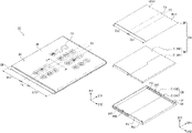
- FIG. 2 is an exploded perspective view showing an electronic device according to an embodiment of the present disclosure
- FIG. 3 A is an exploded perspective view showing a support part according to an embodiment of the present disclosure
- FIG. 3 B is a side view showing a first edge rotating part according to an embodiment of the present disclosure
- FIG. 3 C is a side view showing a second edge rotating part according to an embodiment of the present disclosure.
- FIG. 4 A is a perspective view showing a first accommodating part according to an embodiment of the present disclosure
- FIG. 4 B is a side view showing a first inner side surface of the first accommodating part according to an embodiment of the present disclosure
- FIG. 4 C is a side view showing a first outer side surface of the first accommodating part according to an embodiment of the present disclosure
- FIG. 4 D is a perspective view showing a second accommodating part according to an embodiment of the present disclosure.
- FIG. 4 E is a view showing a second barrier of the second accommodating part according to an embodiment of the present disclosure.
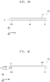
- FIG. 5 A is a cross-sectional view showing an electronic device according to an embodiment of the present disclosure.
- FIG. 5 B is a side view showing an outer side surface of the electronic device of FIG. 5 A ;
- FIG. 5 C is a side view showing an inner side surface of the electronic device of FIG. 5 A ;
- FIG. 6 A is a cross-sectional view showing a folded electronic device according to an embodiment of the present disclosure
- FIG. 6 B is a side view showing an outer side surface of the electronic device of FIG. 6 A ;
- FIG. 6 C is a side view showing an inner side surface of the electronic device of FIG. 6 A ;
- FIG. 7 A is a perspective view showing a portion of an electronic device according to an embodiment of the present disclosure.
- FIG. 7 B is a side view showing an outer side surface of the electronic device of FIG. 7 A ;
- FIG. 7 C is a side view showing an inner side surface of the electronic device of FIG. 6 A ;
- FIG. 8 A is a perspective view showing a portion of an electronic device according to an embodiment of the present disclosure.
- FIG. 8 B is a side view showing an outer side surface of the electronic device of FIG. 8 A ;
- FIG. 8 C is a side view showing an inner side surface of the electronic device of FIG. 8 A ;
- FIG. 9 A is a perspective view showing a portion of an electronic device according to an embodiment of the present disclosure.
- FIG. 9 B is a side view showing an outer side surface of the electronic device of FIG. 9 A ;
- FIG. 9 C is a side view showing an inner side surface of the electronic device of FIG. 9 A .
- first,” “second,” “third” etc. may be used herein to describe various elements, components, regions, layers and/or sections, these elements, components, regions, layers and/or sections should not be limited by these terms. These terms are only used to distinguish one element, component, region, layer or section from another element, component, region, layer or section. Thus, “a first element,” “component,” “region,” “layer” or “section” discussed below could be termed a second element, component, region, layer or section without departing from the teachings herein.
- FIG. 1 A is a perspective view showing an electronic device DD in an unfolded state according to an embodiment of the present disclosure.
- FIG. 1 B is a perspective view showing an electronic device DD-a in a folded state according to an embodiment of the present disclosure.
- the electronic device DD may be activated in response to electrical signals applied thereto.
- the electronic device DD may be a mobile phone, a tablet computer, a car navigation unit, a game unit, or a wearable unit, however, it should not be limited thereto or thereby.
- FIG. 1 A shows a mobile phone as a representative example of the electronic device DD.
- the electronic device DD may be a foldable electronic device.
- the electronic device DD may include a display module DM and an accommodating part CM protecting the display module DM.
- the electronic device DD may display an image IM through an active area DA.
- the active area DA may include a plane substantially parallel to a plane defined by a first direction DR 1 and a second direction DR 2 .
- the display module DM may include a folding area FA foldable with respect to a folding axis FX extending in the first direction DR 1 , a first non-folding area NFA 1 defined adjacent to one side of the folding area FA, and a second non-folding area NFA 2 defined adjacent to the other side of the folding area FA, and the folding area FA may be disposed between the first non-folding area NFA 1 and the second non-folding area NFA 2 . That is, the first non-folding area NFA 1 , the folding area FA, and the second non-folding area NFA 2 may be sequentially arranged in the second direction DR 2 .
- the second direction DR 2 is substantially perpendicular to the first direction DR 1 . As used herein, “substantially perpendicular” includes a case of “perpendicular.”
- FIG. 1 A show one folding area FA and first and second non-folding areas NFA 1 and NFA 2 , however, the number of the folding areas and the number of the non-folding areas according to the invention should not be limited thereto or thereby.
- the display module DM may include three or more non-folding areas and folding areas disposed between the non-folding areas.
- a thickness direction of the electronic device DD may be substantially parallel to a third direction DR 3 crossing the first and second directions DR 1 and DR 2 .
- front (in other words, “upper”) and rear (in other words, “lower”) surfaces of each member of the electronic device DD may be defined with respect to the third direction DR 3 .
- the electronic device DD (refer FIG. 1 A ) may be changed to an electronic device DD-a that is in a folded state of the electronic device DD (refer FIG. 1 A ).
- a display surface of the first non-folding area NFA 1 and a display surface of the second non-folding area NFA 2 may face in opposite directions. That is, a rear surface of the display module DM corresponding to the first non-folding area NFA 1 and a rear surface of the display module DM corresponding to the second non-folding area NFA 2 may face each other.
- the display surface of the first non-folding area NFA 1 and the display surface of the second non-folding area NFA 2 may be referred to as a first display portion DA 1 (refer to FIG. 2 ) and a second display portion DA 2 (refer to FIG. 2 ), respectively.
- the first display portion DA 1 may be covered by the accommodating part CM, and the second display portion DA 2 may be exposed to the outside.
- This folded state may be called an out-folding state.
- the first display portion DA 1 and the second display portion DA 2 may be disposed on the same plane during the non-folded state and may overlap each other in the thickness direction (i.e., third direction DR 3 ) during the folded state.
- the accommodating part CM may cover the entire rear surface of the display module DM in the non-folded state and may cover the first display portion DA 1 of the display module DM in the folded state.
- FIG. 2 is an exploded perspective view showing an electronic device according to an embodiment of the present disclosure.
- the electronic device DD may include the display module DM and the accommodating part CM.
- the display module DM includes a display panel DP and a support part SM.
- the display panel DP may display the image IM (refer to FIG. 1 A ) and may sense an external input.
- the external input may be a user's input.
- the electronic device DD may sense the external input applied to a side surface or a rear surface of the electronic device DD according to a structure of the electronic device DD.
- the display panel DP may include an input sensing layer (not shown) obtaining coordinate information of the external input.
- the display panel DP may be a light-emitting type display panel, however, it should not be particularly limited.
- the display panel DP may be an organic light emitting display panel or a quantum dot light emitting display panel.
- a light emitting layer of the organic light emitting display panel may include an organic light emitting material.
- a light emitting layer of the quantum dot light emitting display panel may include a quantum dot or a quantum rod.
- the input sensing layer may be disposed directly on the display panel DP.
- the input sensing layer may be directly formed on the display panel DP through successive manufacturing processes.
- the input sensing layer may include a plurality of insulating layers and a plurality of conductive layers.
- the conductive layers may include a sensing electrode that senses the external input, a sensing line connected to the sensing electrode, and a sensing pad connected to the sensing line.
- the input sensing layer may sense the external input in a mutual capacitance method and/or a self-capacitance method, however, the method of sensing the external input according to the invention should not be limited thereto or thereby.
- the display panel DP may include the first non-folding area NFA 1 , the folding area FA, and the second non-folding area NFA 2 , which are defined therein and sequentially arranged in the second direction DR 2 . That is, the display panel DP may include the folding area FA foldable around the folding axis FX extending in the first direction DR 1 , the first non-folding area NFA 1 disposed at one side of the folding area FA, and the second non-folding area NFA 2 disposed at the other side of the folding area FA.
- the folding area FA may be disposed between the first non-folding area NFA 1 and the second non-folding area NFA 2 .
- the first display portion DA 1 including the first non-folding area NFA 1 and a portion of the folding area FA and the second display portion DA 2 including the second non-folding area NFA 2 and the other portion of the folding area FA may be defined in the display panel DP with respect to the folding axis FX.
- the folding axis FX, the first non-folding area NFA 1 , the second non-folding area NFA 2 , the folding area FA, the first display portion DA 1 , and the second display portion DA 2 defined in the display panel DP may correspond to the folding axis FX, the first non-folding area NFA 1 , the second non-folding area NFA 2 , the folding area FA, the first display portion DA 1 , and the second display portion DA 2 of the display module DM shown in FIG. 1 A , respectively.
- all the folding area FA, the first non-folding area NFA 1 , and the second non-folding area NFA 2 may serve as the display surface and may be exposed to the outside, and when the display panel DP is in the folded state, the second non-folding area NFA 2 and a portion of the folding area FA may serve as the display surface and may be exposed to the outside.
- the support part SM may be disposed under the display panel DP.
- the support part SM may support a rear surface of the display panel DP.
- the support part SM may include a first support part S-SM 1 that overlaps the first non-folding area NFA 1 and a portion of the folding area FA and a second support part S-SM 2 that overlaps the second non-folding area NFA 2 and the other portion of the folding area FA in a plan view (i.e., view in the third direction DR 3 ).
- the accommodating part CM may be disposed under the support part SM.
- the accommodating part CM may include a first accommodating part S-CM 1 disposed under the first support part S-SM 1 and a second accommodating part S-CM 2 disposed under the second support part S-SM 2 .
- the accommodating part CM may accommodate the display module DM including the display panel DP and the support part SM.
- the first accommodating part S-CM 1 may be slid and then accommodated in the second accommodating part S-CM 2 when the display module DM is folded. That is, the accommodating part CM may be in an open state (corresponding to the unfolded state) before the first accommodating part S-CM 1 slides into the second accommodating part S-CM 2 and in a closed state (corresponding to the folded state) after the first accommodating part S-CM 1 slides into and is accommodated in the second accommodating part S-CM 2 . In the open state, the accommodating part CM may cover the entire rear surface of the display module DM that is in the unfolded state, and in the closed state, the accommodating part CM may cover the first display portion DA 1 of the display module DM.
- FIG. 3 A is an exploded perspective view showing the support part SM according to an embodiment of the present disclosure
- FIG. 3 B is a side view showing a first edge rotating part S-HG 1 according to an embodiment of the present disclosure
- FIG. 3 C is a side view showing a second edge rotating part S-HG 2 according to an embodiment of the present disclosure.
- the support part SM may include the first support part S-SM 1 , the second support part S-SM 2 , a center rotating part HG 1 , two edge rotating parts HG 2 , a first engaging part LM 1 , and a second engaging part LM 2 .
- the first support part S-SM 1 and the second support part S-SM 2 may include a first curved surface SF 1 and a second curved surface SF 2 , respectively, which overlap portions of the folding area FA in a plan view.
- the first curved surface SF 1 and the second curved surface SF 2 may be spaced apart from each other in the first direction DR 1 .
- the center rotating part HG 1 may overlap the folding axis FX and may extend in the first direction DR 1 in a plan view.
- the center rotating part HG 1 may be disposed between the first support part S-SM 1 and the second support part S-SM 2 .
- the center rotating part HG 1 may be accommodated to overlap the first curved surface SF 1 of the first support part S-SM 1 and the second curved surface SF 2 of the second support part S-SM 2 , in a plan view.
- the two edge rotating parts HG 2 may be spaced apart from each other in the first direction DR 1 with the center rotating part HG 1 interposed therebetween.
- Each of the two edge rotating parts HG 2 may include the first edge rotating part S-HG 1 and the second edge rotating part S-HG 2 .
- the first edge rotating part S-HG 1 may be disposed adjacent to the first accommodating part S-CM 1
- the second edge rotating part S-HG 2 may be disposed adjacent to the second accommodating part S-CM 2 .
- the first edge rotating part S-HG 1 may be provided with a first insertion hole HGOP 1 defined in one side thereof and a second insertion hole HGOP 2 in the other side thereof.
- the second insertion hole HGOP 2 is spaced apart from the first insertion hole HGOP 1 in the second direction DR 2 .
- the second edge rotating part S-HG 2 may be provided with a third insertion hole HGOP 3 defined in one side thereof and may have a hook shape at the other side thereof. The hook shape is spaced apart from the third insertion hole HGOP 3 in the second direction DR 2 .
- the second insertion hole HGOP 2 and the third insertion hole HGOP 3 may overlap each other in the side view from the first direction DR 1 .
- the center rotating part HG 1 may be inserted into the second and third insertion holes HGOP 2 and HGOP 3 to couple the first and second edge rotating parts S-HG 1 and S-HG 2 .
- the center rotating part HG 1 may be rotated by a user's operation.
- the edge rotating parts HG 2 coupled to the center rotating part HG 1 may be rotated.
- the first support part S-SM 1 and the second support part S-SM 2 disposed adjacent to the edge rotating parts HG 2 may be disposed to have an included angle therebetween.
- the “included angle” is defined as an angle between two planes.
- the included angle between the first support part S-SM 1 and the second support part S-SM 2 may be within a range from about zero (0) degrees (°) to about 180 degrees (°).
- the folding area FA of the display panel DP disposed on the support part SM may be folded with respect to the folding axis FX. As the display panel DP is folded, the included angle between the first support part S-SM 1 and the second support part S-SM 2 may decrease.
- the first engaging part LM 1 may be inserted into the first insertion hole HGOP 1 .
- the second engaging part LM 2 may be inserted into and may be fixed to the hook shape of the second edge rotating part S-HG 2 .
- the first engaging part LM 1 and the second engaging part LM 2 will be described in detail later.
- FIG. 4 A is a perspective view showing the first accommodating part S-CM 1 according to an embodiment of the present disclosure.
- the first accommodating part S-CM 1 may include a first bottom surface BA 1 and first barriers PW 1 perpendicular to the first bottom surface BA 1 and facing each other in the first direction DR 1 .
- the first barriers PW 1 may refer to side surfaces of the first accommodating part S-CM 1 extending in a direction substantially parallel to the second direction DR 2 .
- Each of the first barriers PW 1 may include a first inner side surface IA 1 and a first outer side surface OA 1 opposite to the first inner side surface IA 1 .
- the first accommodating part S-CM 1 may include a first surface extending in the first direction DR 1 and having a first length L 1 .
- the first barriers PW 1 facing each other in the first direction DR 1 may have the same shape as each other.
- FIG. 4 B is a side view showing the first inner side surface IA 1 of the first accommodating part S-CM 1 according to an embodiment of the present disclosure.
- the first barrier PW 1 in FIG. 4 B corresponds to the first barrier PW 1 that is disposed right with respect to the first bottom surface BA 1 in FIG. 4 A .
- the first inner side surface IA 1 may be provided with a first hole OP 1 into which the first engaging part LM 1 (refer to FIG. 3 A ) is inserted, a second hole OP 2 spaced apart from the first hole OP 1 in the second direction DR 2 , and a first guide part GM 1 defined between the first hole OP 1 and the second hole OP 2 and extending in the second direction DR 2 .
- the first and second holes OP 1 and OP 2 may penetrate the first inner side surface IA 1 and the first outer side surface OA 1 of the first barriers PW 1 .
- the first guide part GM 1 may be concavely defined (i.e., recessed) in a direction from the first inner side surface IA 1 to the first outer side surface OA 1 (i.e., the first direction DR 1 ).
- the first guide part GM 1 may be a path through which the first engaging part LM 1 (refer to FIG. 3 A ) moves between the second hole OP 2 and the first hole OP 1 in the second direction DR 2 .
- the first guide part GM 1 is defined as a concave part, however, this is merely exemplary, and the present disclosure according to the invention should not be limited thereto or thereby.
- the first guide part GM 1 may be a hole penetrating the first inner side surface IA 1 and the first outer side surface OA 1 .
- the first accommodating part S-CM 1 may be provided with a concave portion CA defined at one end thereof, which is adjacent to the second accommodating part S-CM 2 , and the concave portion CA is recessed toward the second hole OP 2 .
- the concave portion CA may have substantially the same width as that of the second hole OP 2 in a thickness direction (i.e., third direction DR 3 ).
- FIG. 4 C is a side view showing the first outer side surface OA 1 of the first accommodating part S-CM 1 according to an embodiment of the present disclosure.
- the first barrier PW 1 in FIG. 4 C corresponds to the first barrier PW 1 that is disposed left with respect to the first bottom surface BA 1 in FIG. 4 A .
- the first outer side surface OA 1 may be provided with a protrusion part PP protruded from one end thereof, which is adjacent to the second accommodating part S-CM 2 .
- the protrusion part PP may include a first protrusion part S-PP 1 and a second protrusion part S-PP 2 spaced apart from the first protrusion part S-PP 1 with the second hole OP 2 interposed therebetween in the thickness direction (i.e., the third direction DR 3 ), however, this is merely exemplary, and the present disclosure according to the invention should not be limited thereto or thereby. As another way, the protrusion part PP may be provided in a singular or plural number in another embodiment.
- FIG. 4 D is a perspective view showing the second accommodating part S-CM 2 according to an embodiment of the present disclosure.
- the second accommodating part S-CM 2 may include a second bottom surface BA 2 and second barriers PW 2 perpendicular to the second bottom surface BA 2 and facing each other in the first direction DR 1 .
- the second barriers PW 2 may refer to side surfaces of the second accommodating part S-CM 2 extending in a direction substantially parallel to the second direction DR 2 .
- Each of the second barriers PW 2 may include a second inner side surface IA 2 and a second outer side surface OA 2 opposite to the second inner side surface IA 2 .
- the second accommodating part S-CM 2 may include a second surface extending in the first direction DR 1 and having a second length L 2 greater than the first length L 1 of the first surface (refer to FIG. 4 A ).
- the second barriers PW 2 facing each other in the first direction DR 1 may have the same shape as each other.
- FIG. 4 E is a view showing the second barrier PW 2 of the second accommodating part S-CM 2 according to an embodiment of the present disclosure.
- the second barrier PW 2 in FIG. 4 E corresponds to the second barrier PW 2 that is disposed right with respect to the second bottom surface BA 2 in FIG. 4 D .
- the second barrier PW 2 may be provided with a third hole OP 3 , a fourth hole OP 4 , and second guide part GM 2 .
- the third hole OP 3 may be defined in one side thereof and overlapping the concave portion CA in the unfolded state in the first direction DR 1
- the fourth hole OP 4 may be spaced apart from the third hole OP 3 in the second direction DR 2
- the second guide part GM 2 may overlap the protrusion part PP (refer to FIG. 4 C ) in the first direction DR 1 and extend in the second direction DR 2 .
- the second engaging part LM 2 (refer to FIG. 3 A ) may be inserted into the fourth hole OP 4 .
- the third hole OP 3 and the fourth hole OP 4 may penetrate the second inner side surface IA 2 and the second outer side surface OA 2 of the second barrier PW 2 .
- the second guide part GM 2 may be defined through the second inner side surface IA 2 and the second outer side surface OA 2 of the second barrier PW 2 .
- the second guide part GM 2 may serve as a path through which the protrusion part PP (refer to FIG. 4 C ) slides to the second direction DR 2 by the user's operation.
- the second guide part GM 2 may include a first sub-guide part S-GM 1 and a second sub-guide part S-GM 2 spaced apart from the first sub-guide part S-GM 1 with the third and fourth holes OP 3 and OP 4 interposed therebetween in the thickness direction (i.e., the third direction DR 3 ).
- This is merely exemplary, and the present disclosure according to the invention should not be limited thereto or thereby.
- the second guide part GM 2 may be provided in a singular number or may include a plurality of sub-guide parts in another embodiment.
- FIG. 5 A is a cross-sectional view taken along line I-I′ of FIG. 1 A to show the electronic device in an unfolded state according to an embodiment of the present disclosure.
- FIG. 5 B is a side view showing an outer side surface of the electronic device of FIG. 5 A
- FIG. 5 C is a side view showing an inner side surface of the electronic device.
- FIGS. 5 A to 5 C the same descriptions as those of FIGS. 1 A to 4 E will be omitted, and different features will be mainly described.
- the electronic device DD in the unfolded state will be described in detail with reference to FIGS. 5 A to 5 C .
- the first display portion DA 1 may overlap the first accommodating part S-CM 1
- the second display portion DA 2 may overlap the second accommodating part S-CM 2 in a plan view in a first state (i.e., the unfolded state) in which the first and second display portions DA 1 and DA 2 of the electronic device DD are disposed on the same plane.
- the first engaging part LM 1 when the electronic device DD is in the first state, the first engaging part LM 1 may be inserted into the first hole OP 1 , and the protrusion part PP may be inserted into one side of the second guide part GM 2 adjacent to the third hole OP 3 .
- the second engaging part LM 2 may be inserted into and may be fixed to the fourth hole OP 4 in both the folded state and the unfolded state.
- FIG. 6 A is a cross-sectional view taken along line II-II′ of FIG. 1 B to show the electronic device DD-a in the completely folded state according to an embodiment of the present disclosure
- FIG. 6 B is a side view showing an outer side surface of the accommodating part of the electronic device DD-a in the folded state
- FIG. 6 C is a side view showing an inner side surface of the electronic device DD-a in the folded state.
- the electronic device DD-a when the electronic device DD-a is in a second state (i.e., the completely folded state) in which the electronic device DD-a is completely folded to allow the first display portion DA 1 to overlap the second display portion DA 2 in a plan view, the second display portion DA 2 , the first display portion DA 1 , the first bottom surface BA 1 (which is a part of the first accommodating part S-CM 1 ), and the second bottom surface BA 2 (which is a part of the second accommodating part S-CM 2 ) may overlap with each other in a plan view.
- a second state i.e., the completely folded state
- the electronic device DD-a when the electronic device DD-a is in a second state in which the electronic device DD-a is completely folded to allow the first display portion DA 1 to overlap the second display portion DA 2 in a plan view
- the first support part S-SM 1 and the second support part S-SM 2 may be disposed to overlap each other due to the rotation of the center rotating part HG 1 and the operation of the two edge rotating parts HG 2 , which is caused by the rotation of the center rotating part HG 1 , in the first state, and the first display portion DA 1 and the second display portion DA 2 may be disposed to overlap each other in a plan view due to the folding of the display panel DP disposed on the support part SM.
- the concave portion CA may be located adjacent to the fourth hole OP 4 when the electronic device DD-a is in the second state.
- the first engaging part LM 1 may be engaged with the second hole OP 2 .
- the protrusion part PP may be inserted into one side of the second guide part GM 2 , which is adjacent to the fourth hole OP 4 .
- FIG. 7 A is a perspective view showing a portion of an electronic device DD-b in a third state (i.e., one of intermediately folded states) according to an embodiment of the present disclosure
- FIG. 7 B is a side view showing an outer side surface of the electronic device DD-b of FIG. 7 A
- FIG. 7 C is a side view showing an inner side surface of the electronic device DD-b of FIG. 7 A .
- the electronic device DD-b in the third state will be described in detail with reference to FIGS. 7 A to 7 C .
- the folding area FA of the display module DM of the electronic device DD-b may be spaced apart from the first accommodating part S-CM 1 and the second accommodating part S-CM 2 in a thickness direction (the third direction DR 3 ).
- the first display portion DA 1 (refer to FIG. 2 ) and the second display portion DA 2 (refer to FIG. 2 ) of the display module DM may be disposed to have a first included angle AG 1 .
- the first included angle AG 1 may be greater than about 70 degrees (°) and smaller than about 180 degrees (°).
- the display panel DP (refer to FIG. 2 ) and the support part SM(refer to FIG. 2 ) are omitted from FIGS. 7 A to 7 C to show a position relationship between the center rotating part HG 1 , the two edge rotating parts HG 2 , and the accommodating part CM.
- a surface defined by the center rotating part HG 1 , the first edge rotating parts S-HG 1 , and a virtual line connecting two points where the first accommodating part S-CM 1 and the first edge rotating parts S-HG 1 meet may correspond to the first display portion DA 1 (refer to FIG.
- an angle defined by the first display portion DA 1 (refer to FIG. 2 ) and the second display portion DA 2 (refer to FIG. 2 ) may be defined as being the same as an angle defined by the first edge rotating part S-HG 1 and the second edge rotating part S-HG 2 .
- the first engaging part LM 1 coupled to one end of the first edge rotating part S-HG 1 may be inserted into the first guide part GM 1 in the electronic device DD-b.
- the edge rotating parts HG 2 When the center rotating part HG 1 is rotated in the first state, the edge rotating parts HG 2 may be disposed to be inclined with respect to the accommodating part CM and may have the first included angle AG 1 , and thus, the electronic device DD-b may be in the third state.
- the first engaging part LM 1 coupled to the first edge rotating part S-HG 1 may slide in the second direction DR 2 from the first hole OP 1 , and then, may be inserted into the first guide part GM 1 .
- FIG. 8 A is a perspective view showing a portion of an electronic device DD-c in a fourth state (i.e., another of intermediately folded states) according to an embodiment of the present disclosure
- FIG. 8 B is a side view showing an outer side surface of the electronic device DD-c of FIG. 8 A
- FIG. 8 C is a side view showing an inner side surface of the electronic device DD-c of FIG. 8 A .
- the electronic device DD-c in the fourth state will be described in detail with reference to FIGS. 8 A to 8 C .
- the folding area FA of the display module DM of the electronic device DD-c may be further spaced apart from the first accommodating part S-CM 1 and the second accommodating part S-CM 2 in the thickness direction (i.e., the third direction DR 3 ) than in the third state.
- the first edge rotating part S-HG 1 and the second edge rotating part S-HG 2 may be disposed to be more inclined with respect to the accommodating part CM to have a second included angle AG 2 smaller than the first included angle AG 1 .
- the second included angle AG 2 may be equal to or greater than about 50 degrees (°) and equal to or smaller than about 70 degrees (°).
- the first engaging part LM 1 may be inserted into the second hole OP 2 in the electronic device DD-c.
- the edge rotating parts HG 2 are disposed to be more inclined with respect to the accommodating part CM in the fourth state than that in the third state, the first engaging part LM 1 coupled to the first edge rotating part S-HG 1 may slide along the second direction DR 2 in the first guide part GM 1 , and thus, may be inserted into the second hole OP 2 .
- FIG. 9 A is a perspective view showing a portion of an electronic device DD-d in a fifth state (i.e., still another of intermediately folded states) according to an embodiment of the present disclosure
- FIG. 9 B is a side view showing an outer side surface of the electronic device DD-d of FIG. 9 A
- FIG. 9 C is a side view showing an inner side surface of the electronic device DD-d of FIG. 9 A .
- the electronic device DD-d in the fifth state will be described in detail with reference to FIGS. 9 A to 9 C .
- the display module DM may be further spaced apart from the first accommodating part S-CM 1 and the second accommodating part S-CM 2 in the thickness direction (i.e., the third direction DR 3 ) than in the fourth state.
- the first edge rotating part S-HG 1 and the second edge rotating part S-HG 2 may be disposed to be more inclined with respect to the accommodating part CM to have a third included angle AG 3 smaller than the second included angle AG 2 .
- the third included angle AG 3 may be equal to or greater than about 0 degrees (°) and smaller than about 50 degrees (°).
- the area in which the first accommodating part S-CM 1 overlaps the second accommodating part S-CM 2 in the first direction DR 1 may increase in the fifth state compared with that in the fourth state, and the area in which the first accommodating part S-CM 1 is exposed to the outside may decrease in the fifth state compared with that in the fourth state.
- the protrusion part PP inserted into the second guide part GM 2 may move to the fourth hole OP 4 from the third hole OP 3 while the fourth state is changed to the second state (i.e., the completely folded state). That is, the protrusion part PP may move from one end of the second guide part GM 2 , which is adjacent to the third hole OP 3 , to the other end of the second guide part GM 2 , which is adjacent to the fourth hole OP 4 , in the fifth state.
- the edge rotating parts HG 2 are disposed to be more inclined with respect to the accommodating part CM in the fifth state than that in the fourth state, the first accommodating part S-CM 1 coupled to the first edge rotating part S-HG 1 by the first engaging part LM 1 may slide toward the second accommodating part S-CM 2 .
- the operation in which the first accommodating part S-CM 1 slides to the second accommodating part S-CM 2 may mean that the protrusion part PP slides along the second guide part GM 2 .
- the changing from the fifth state to the second state may mean that the included angle between the first edge rotating part S-HG 1 and the second edge rotating part S-HG 2 is changed from the third included angle AG 3 to zero. That is, the included angle between the first edge rotating part S-HG 1 and the second edge rotating part S-HG 2 may decrease as the first state is changed to the second state (i.e., the completely folded state).
- the electronic device DD includes the display module DM that includes the first and second display portions DA 1 and DA 2 distinguished from each other with respect to the folding axis FX and the accommodating part CM that slides along the second direction DR 2 . Accordingly, the second display portion DA 2 is exposed to the outside in the folded state, and the first display portion DA 1 is covered by the accommodating part CM in the folded state, thereby protecting the portion of the display surface from the external impacts.
Abstract
Description
Claims (19)
Applications Claiming Priority (2)
| Application Number | Priority Date | Filing Date | Title |
|---|---|---|---|
| KR10-2020-0083919 | 2020-07-08 | ||
| KR1020200083919A KR20220006671A (en) | 2020-07-08 | 2020-07-08 | Electronic device |
Publications (2)
| Publication Number | Publication Date |
|---|---|
| US20220011816A1 US20220011816A1 (en) | 2022-01-13 |
| US11550357B2 true US11550357B2 (en) | 2023-01-10 |
Family
ID=79173572
Family Applications (1)
| Application Number | Title | Priority Date | Filing Date |
|---|---|---|---|
| US17/229,072 Active US11550357B2 (en) | 2020-07-08 | 2021-04-13 | Electronic device |
Country Status (3)
| Country | Link |
|---|---|
| US (1) | US11550357B2 (en) |
| KR (1) | KR20220006671A (en) |
| CN (1) | CN113920861A (en) |
Citations (19)
| Publication number | Priority date | Publication date | Assignee | Title |
|---|---|---|---|---|
| US20150257289A1 (en) * | 2014-03-07 | 2015-09-10 | Lg Display Co., Ltd. | Foldable display apparatus |
| US9572272B2 (en) * | 2014-03-05 | 2017-02-14 | Lg Display Co., Ltd. | Foldable display apparatus |
| KR101748692B1 (en) | 2016-10-25 | 2017-06-20 | 주식회사 가난한동지들 | A Protection Case with a view window on its swing back panel for Out Folding Display Device with Flexible Display Panel |
| KR101784880B1 (en) | 2017-04-02 | 2017-10-16 | 주식회사 가난한동지들 | Display apparatus with A Capability of A folding and Rolling Flexible Display |
| US20170357289A1 (en) * | 2016-06-09 | 2017-12-14 | Samsung Display Co., Ltd. | Foldable display device |
| KR20180087826A (en) | 2017-11-21 | 2018-08-02 | 주식회사 가난한동지들 | Case for Out-Folding Display Device with Flexible Display Panel |
| US10433438B2 (en) | 2016-09-13 | 2019-10-01 | Samsung Electronics Co., Ltd. | Flexible display electronic device |
| US10503211B2 (en) * | 2015-09-13 | 2019-12-10 | Intel Corporation | Multi-orientation display device |
| KR20190143029A (en) | 2018-06-19 | 2019-12-30 | 삼성전자주식회사 | Electronic device including a flexible display and an antenna |
| KR20200018282A (en) | 2018-08-10 | 2020-02-19 | 삼성전자주식회사 | Foldable electronic device including an antenna |
| US10645205B2 (en) * | 2018-02-02 | 2020-05-05 | Samsung Display Co., Ltd. | Foldable device and method for controlling the same |
| US10694624B2 (en) * | 2011-07-06 | 2020-06-23 | Apple Inc. | Flexible display devices |
| US20200375046A1 (en) * | 2019-05-23 | 2020-11-26 | Samsung Display Co., Ltd. | Foldable display device |
| US20200393931A1 (en) * | 2019-06-14 | 2020-12-17 | Samsung Display Co., Ltd. | Display device |
| US20210018962A1 (en) * | 2019-07-17 | 2021-01-21 | Google Llc | Hinge mechanism with integrated slider and foldable device having same |
| US20210181807A1 (en) * | 2018-08-31 | 2021-06-17 | Hewlett-Packard Development Company, L.P. | Suspensions for displays |
| US20210298186A1 (en) * | 2017-05-02 | 2021-09-23 | Samsung Electronics Co., Ltd. | Electronic device including flexible display |
| US11181763B2 (en) * | 2016-09-21 | 2021-11-23 | Samsung Display Co., Ltd. | Display device |
| US20210365074A1 (en) * | 2018-11-02 | 2021-11-25 | Hewlett-Packard Development Company, L.P. | Magnetic suspensions for displays |
-
2020
- 2020-07-08 KR KR1020200083919A patent/KR20220006671A/en active Search and Examination
-
2021
- 2021-04-13 US US17/229,072 patent/US11550357B2/en active Active
- 2021-07-07 CN CN202110765028.4A patent/CN113920861A/en active Pending
Patent Citations (23)
| Publication number | Priority date | Publication date | Assignee | Title |
|---|---|---|---|---|
| US11304316B2 (en) * | 2011-07-06 | 2022-04-12 | Apple Inc. | Flexible display devices |
| US10694624B2 (en) * | 2011-07-06 | 2020-06-23 | Apple Inc. | Flexible display devices |
| US9572272B2 (en) * | 2014-03-05 | 2017-02-14 | Lg Display Co., Ltd. | Foldable display apparatus |
| US20150257289A1 (en) * | 2014-03-07 | 2015-09-10 | Lg Display Co., Ltd. | Foldable display apparatus |
| US9603271B2 (en) * | 2014-03-07 | 2017-03-21 | Lg Display Co., Ltd. | Foldable display apparatus |
| US10503211B2 (en) * | 2015-09-13 | 2019-12-10 | Intel Corporation | Multi-orientation display device |
| US20170357289A1 (en) * | 2016-06-09 | 2017-12-14 | Samsung Display Co., Ltd. | Foldable display device |
| US10433438B2 (en) | 2016-09-13 | 2019-10-01 | Samsung Electronics Co., Ltd. | Flexible display electronic device |
| US11181763B2 (en) * | 2016-09-21 | 2021-11-23 | Samsung Display Co., Ltd. | Display device |
| US20200037716A1 (en) | 2016-10-25 | 2020-02-06 | Ganahandongjidul Inc. | Protective case of out-folding image display device provided with flexible display device having lower cover to which screen transmission window is applied |
| KR101748692B1 (en) | 2016-10-25 | 2017-06-20 | 주식회사 가난한동지들 | A Protection Case with a view window on its swing back panel for Out Folding Display Device with Flexible Display Panel |
| KR101784880B1 (en) | 2017-04-02 | 2017-10-16 | 주식회사 가난한동지들 | Display apparatus with A Capability of A folding and Rolling Flexible Display |
| US20210298186A1 (en) * | 2017-05-02 | 2021-09-23 | Samsung Electronics Co., Ltd. | Electronic device including flexible display |
| KR20180087826A (en) | 2017-11-21 | 2018-08-02 | 주식회사 가난한동지들 | Case for Out-Folding Display Device with Flexible Display Panel |
| US10645205B2 (en) * | 2018-02-02 | 2020-05-05 | Samsung Display Co., Ltd. | Foldable device and method for controlling the same |
| KR20190143029A (en) | 2018-06-19 | 2019-12-30 | 삼성전자주식회사 | Electronic device including a flexible display and an antenna |
| KR20200018282A (en) | 2018-08-10 | 2020-02-19 | 삼성전자주식회사 | Foldable electronic device including an antenna |
| US20210181807A1 (en) * | 2018-08-31 | 2021-06-17 | Hewlett-Packard Development Company, L.P. | Suspensions for displays |
| US11256304B2 (en) * | 2018-08-31 | 2022-02-22 | Hewlett-Packard Development Company, L.P. | Suspensions for displays |
| US20210365074A1 (en) * | 2018-11-02 | 2021-11-25 | Hewlett-Packard Development Company, L.P. | Magnetic suspensions for displays |
| US20200375046A1 (en) * | 2019-05-23 | 2020-11-26 | Samsung Display Co., Ltd. | Foldable display device |
| US20200393931A1 (en) * | 2019-06-14 | 2020-12-17 | Samsung Display Co., Ltd. | Display device |
| US20210018962A1 (en) * | 2019-07-17 | 2021-01-21 | Google Llc | Hinge mechanism with integrated slider and foldable device having same |
Also Published As
| Publication number | Publication date |
|---|---|
| KR20220006671A (en) | 2022-01-18 |
| US20220011816A1 (en) | 2022-01-13 |
| CN113920861A (en) | 2022-01-11 |
Similar Documents
| Publication | Publication Date | Title |
|---|---|---|
| US10224502B2 (en) | Window and display device having the same | |
| US9730318B2 (en) | Rollable display device, method of manufacturing the same, and flexible display device | |
| US10121988B2 (en) | Flexible display device | |
| US11455916B2 (en) | Display device | |
| JP7107833B2 (en) | FLEXIBLE TOUCH SCREEN AND MANUFACTURING METHOD, DISPLAY SCREEN AND MANUFACTURING METHOD, DISPLAY DEVICE | |
| US9655235B2 (en) | Foldable display device | |
| US8539705B2 (en) | Crossfold electronic device | |
| TWI391732B (en) | Partially flexible display device | |
| US9971380B2 (en) | Flexible display apparatus | |
| KR20160069560A (en) | Foldable display device | |
| TW201740590A (en) | Display device | |
| US8010169B2 (en) | Handheld electronic device | |
| US20210150944A1 (en) | Display device and electronic apparatus having the same | |
| US11500506B2 (en) | Display device including a digitizer with reduced wiring visibility | |
| US11455005B2 (en) | Display device | |
| US20230052358A1 (en) | Display device | |
| US11550357B2 (en) | Electronic device | |
| US11877467B2 (en) | Display device | |
| US11672157B2 (en) | Electronic apparatus | |
| CN115331546A (en) | Display device | |
| KR20210116840A (en) | Display apparatus | |
| US11747869B2 (en) | Display device | |
| US20230225172A1 (en) | Display panel | |
| CN113377233A (en) | Foldable touch module and foldable display device | |
| KR20230049191A (en) | Display apparatus and method of manufacturing the same |
Legal Events
| Date | Code | Title | Description |
|---|---|---|---|
| FEPP | Fee payment procedure |
Free format text: ENTITY STATUS SET TO UNDISCOUNTED (ORIGINAL EVENT CODE: BIG.); ENTITY STATUS OF PATENT OWNER: LARGE ENTITY |
|
| STPP | Information on status: patent application and granting procedure in general |
Free format text: DOCKETED NEW CASE - READY FOR EXAMINATION |
|
| STPP | Information on status: patent application and granting procedure in general |
Free format text: NON FINAL ACTION MAILED |
|
| AS | Assignment |
Owner name: SAMSUNG DISPLAY CO., LTD., KOREA, REPUBLIC OF Free format text: ASSIGNMENT OF ASSIGNORS INTEREST;ASSIGNOR:LEE, JIHEON;REEL/FRAME:059980/0326 Effective date: 20210128 |
|
| STPP | Information on status: patent application and granting procedure in general |
Free format text: RESPONSE TO NON-FINAL OFFICE ACTION ENTERED AND FORWARDED TO EXAMINER |
|
| STPP | Information on status: patent application and granting procedure in general |
Free format text: NOTICE OF ALLOWANCE MAILED -- APPLICATION RECEIVED IN OFFICE OF PUBLICATIONS |
|
| STPP | Information on status: patent application and granting procedure in general |
Free format text: PUBLICATIONS -- ISSUE FEE PAYMENT VERIFIED |
|
| STCF | Information on status: patent grant |
Free format text: PATENTED CASE |