US11547198B2 - Sustainable dispensing package having a telescopic actuator - Google Patents
Sustainable dispensing package having a telescopic actuator Download PDFInfo
- Publication number
- US11547198B2 US11547198B2 US17/195,711 US202117195711A US11547198B2 US 11547198 B2 US11547198 B2 US 11547198B2 US 202117195711 A US202117195711 A US 202117195711A US 11547198 B2 US11547198 B2 US 11547198B2
- Authority
- US
- United States
- Prior art keywords
- tubular
- screw
- elevator
- replaceable cartridge
- tubular body
- Prior art date
- Legal status (The legal status is an assumption and is not a legal conclusion. Google has not performed a legal analysis and makes no representation as to the accuracy of the status listed.)
- Active, expires
Links
Images


Classifications
-
- A—HUMAN NECESSITIES
- A45—HAND OR TRAVELLING ARTICLES
- A45D—HAIRDRESSING OR SHAVING EQUIPMENT; EQUIPMENT FOR COSMETICS OR COSMETIC TREATMENTS, e.g. FOR MANICURING OR PEDICURING
- A45D40/00—Casings or accessories specially adapted for storing or handling solid or pasty toiletry or cosmetic substances, e.g. shaving soaps or lipsticks
- A45D40/14—Casings with ejector for waste stick or the like
-
- A—HUMAN NECESSITIES
- A45—HAND OR TRAVELLING ARTICLES
- A45D—HAIRDRESSING OR SHAVING EQUIPMENT; EQUIPMENT FOR COSMETICS OR COSMETIC TREATMENTS, e.g. FOR MANICURING OR PEDICURING
- A45D40/00—Casings or accessories specially adapted for storing or handling solid or pasty toiletry or cosmetic substances, e.g. shaving soaps or lipsticks
- A45D40/02—Casings wherein movement of the lipstick or like solid is a sliding movement
- A45D40/04—Casings wherein movement of the lipstick or like solid is a sliding movement effected by a screw
-
- A—HUMAN NECESSITIES
- A45—HAND OR TRAVELLING ARTICLES
- A45D—HAIRDRESSING OR SHAVING EQUIPMENT; EQUIPMENT FOR COSMETICS OR COSMETIC TREATMENTS, e.g. FOR MANICURING OR PEDICURING
- A45D40/00—Casings or accessories specially adapted for storing or handling solid or pasty toiletry or cosmetic substances, e.g. shaving soaps or lipsticks
- A45D40/16—Refill sticks; Moulding devices for producing sticks
-
- B—PERFORMING OPERATIONS; TRANSPORTING
- B65—CONVEYING; PACKING; STORING; HANDLING THIN OR FILAMENTARY MATERIAL
- B65D—CONTAINERS FOR STORAGE OR TRANSPORT OF ARTICLES OR MATERIALS, e.g. BAGS, BARRELS, BOTTLES, BOXES, CANS, CARTONS, CRATES, DRUMS, JARS, TANKS, HOPPERS, FORWARDING CONTAINERS; ACCESSORIES, CLOSURES, OR FITTINGS THEREFOR; PACKAGING ELEMENTS; PACKAGES
- B65D83/00—Containers or packages with special means for dispensing contents
- B65D83/76—Containers or packages with special means for dispensing contents for dispensing fluent contents by means of a piston
- B65D83/761—Containers or packages with special means for dispensing contents for dispensing fluent contents by means of a piston the piston being actuated by a screw-shaft
-
- A—HUMAN NECESSITIES
- A45—HAND OR TRAVELLING ARTICLES
- A45D—HAIRDRESSING OR SHAVING EQUIPMENT; EQUIPMENT FOR COSMETICS OR COSMETIC TREATMENTS, e.g. FOR MANICURING OR PEDICURING
- A45D34/00—Containers or accessories specially adapted for handling liquid toiletry or cosmetic substances, e.g. perfumes
- A45D2034/005—Containers or accessories specially adapted for handling liquid toiletry or cosmetic substances, e.g. perfumes with a cartridge
-
- A—HUMAN NECESSITIES
- A45—HAND OR TRAVELLING ARTICLES
- A45D—HAIRDRESSING OR SHAVING EQUIPMENT; EQUIPMENT FOR COSMETICS OR COSMETIC TREATMENTS, e.g. FOR MANICURING OR PEDICURING
- A45D40/00—Casings or accessories specially adapted for storing or handling solid or pasty toiletry or cosmetic substances, e.g. shaving soaps or lipsticks
- A45D2040/0025—Details of lipstick or like casings
- A45D2040/0031—Replacement of the stick
- A45D2040/0043—Replacement of the stick by inserting the new stick at the upper, applying end of the casing
-
- A—HUMAN NECESSITIES
- A45—HAND OR TRAVELLING ARTICLES
- A45D—HAIRDRESSING OR SHAVING EQUIPMENT; EQUIPMENT FOR COSMETICS OR COSMETIC TREATMENTS, e.g. FOR MANICURING OR PEDICURING
- A45D2200/00—Details not otherwise provided for in A45D
- A45D2200/05—Details of containers
Definitions
- the present application generally relates to dispensing packages for a spreadable personal care product and its respective methods for manufacturing the dispensing packages, and for dispensing and applying a spreadable personal care product.
- the dispensing package comprises a reusable dispenser and a replaceable cartridge, and optionally a top cap.
- the reusable dispenser comprises a tubular body and a telescopic actuator. The telescopic actuator is able to engage with a push plate of the replaceable cartridge to deliver the personal care product such that a top surface of the elevator telescopes with a bottom surface of the push plate of the replaceable cartridge.
- Personal care products such as antiperspirants and deodorants for instance as a stick form product are typically packaged in what is referred to as swivel-up or elevator/threaded-shaft dispensing packages.
- Such dispensing packages typically have a body with an oval cross-section having a threaded shaft axially oriented therein and rotatably mounted at the bottom end through an aperture.
- the threaded shaft is typically connected to a hand wheel on the exterior of the package's bottom for advancing the personal care product out of the package.
- An elevator or follower is threadably mounted to the shaft on the interior of the package at its bottom. Turning the hand wheel in a predetermined direction will either advance the elevator towards the top of the package or retract it back towards the bottom.
- the personal care product is typically poured into the dispensing package in its liquid or molten state, with the elevator in its lowermost position, whereby upon cooling the personal care product solidifies and takes on the shape of the dispensing package. Thereafter, to dispense the stick form product from the dispensing package one turns the hand wheel thereby rotating the threaded shaft and advancing the elevator towards the top of the dispensing package. As the elevator advances toward the top of the dispensing package, it pushes the stick form product up and out of the top of the dispensing package so the user can have access.
- dispensing packages In order to reduce solid waste landfill volume, there is still a desire to develop dispensing packages partially reusable so that the entire package does not have to be thrown away after the initial personal care product is used up.
- One way to accomplish this is to design a dispensing package that has a reusable dispenser designed to receive a replaceable cartridge containing the personal care product, see for instance U.S. Pat. No. 5,255,990. After the initial personal care product in the dispensing package is used up, the initial replaceable cartridge is discarded and a new replaceable cartridge is inserted into the reusable dispenser, thereby rendering the dispensing package partially reusable.
- the replaceable cartridge disclosed in U.S. Pat. No. 5,255,990 includes a means for delivering the personal care product to the consumer by providing a telescoping elevator system comprising an internally threaded neck and an elevator platform.
- the internally threaded neck is adapted to receive threaded shaft in threaded telescoping relation.
- Plastic packaging uses nearly 40% of all polymers, a substantial share of which is used for consumer products, such as personal care packages (e.g., antiperspirant, deodorant stick bottles).
- Most of the materials used to produce polymers for plastic packaging applications such as polyethylene, polyethylene terephthalate, and polypropylene, are derived from monomers (e.g., ethylene, propylene, terephthalic acid, ethylene glycol), which are obtained from non-renewable, fossil-based resources, such as petroleum, natural gas, and coal.
- monomers e.g., ethylene, propylene, terephthalic acid, ethylene glycol
- non-renewable resources such as petroleum, natural gas, and coal.
- Many consumers display an aversion to purchasing products that are derived from petrochemicals. In some instances, consumers are hesitant to purchase products made from limited non-renewable resources (e.g., petroleum, natural gas and coal). Other consumers may have adverse perceptions about products derived from petrochemicals as
- the reusable dispenser shall be improved such that the replaceable cartridge shall be relatively easier to insert into the reusable dispenser without having to manipulate the replaceable cartridge itself.
- a dispensing package 1 for a spreadable personal care product comprises: a reusable dispenser 3 , a replaceable cartridge 8 and optionally a top cap 2 ; wherein the reusable dispenser 3 comprises: a longitudinal axis L; a tubular body 6 having an open top 61 and an open bottom 62 , wherein the tubular body 6 comprises an upper top portion 66 and a lower bottom portion 67 , wherein the tubular body 6 has a coupling sleeve 63 disposed inside the lower bottom portion 67 forming a central opening 630 coaxial to the longitudinal axis L; and a telescopic actuator 5 axially oriented within the tubular body 6 and mounted through the open bottom 62 of the tubular body 6 into the coupling sleeve 63 ; wherein the telescopic actuator 5 comprises: a hand wheel 51 having an inner surface 512 and a perimeter wall 510 , wherein the perimeter wall 510 extends around the lower bottom portion 67 of the tubular body 6 ; a central
- a reusable dispenser 3 for a spreadable personal care product comprises: a longitudinal axis L; a tubular body 6 having an open top 61 and an open bottom 62 , wherein the tubular body 6 comprises an upper top portion 66 and a lower bottom portion 67 , wherein the tubular body 6 has a coupling sleeve 63 disposed inside the lower bottom portion 67 forming a central opening 630 coaxial to the longitudinal axis L; and a telescopic actuator 5 axially oriented within the tubular body 6 and mounted through the open bottom 62 of the tubular body 6 into the coupling sleeve 63 ; wherein the telescopic actuator 5 comprises: a hand wheel 51 having an inner surface 512 and a perimeter wall 510 , wherein the perimeter wall 510 extends around the lower bottom portion 67 of the tubular body 6 ; a central shaft 52 connected to the hand wheel 51 , wherein the central shaft 52 extends from the inner surface 512 of the hand wheel 51 into the coupling
- a method for dispensing a spreadable personal care product comprises the following steps in that order:
- a reusable dispenser 3 wherein the reusable dispenser 3 comprises: a longitudinal axis L, a tubular body 6 having an open top 61 and an open bottom 62 , wherein the tubular body 6 comprises an upper top portion 66 and a lower bottom portion 67 , wherein the tubular body 6 has a coupling sleeve 63 disposed inside the lower bottom portion 67 forming a central opening 630 coaxial to the longitudinal axis L; and a telescopic actuator 5 axially oriented within the tubular body 6 and mounted through the open bottom 62 of the tubular body 6 into the coupling sleeve 63 ; wherein the telescopic actuator 5 comprises: a hand wheel 51 having an inner surface 512 and a perimeter wall 510 , wherein the perimeter wall 510 extends around the lower bottom portion 67 of the tubular body 6 ; a central shaft 52 connected to the hand wheel 51 , wherein the central shaft 52 extends from the inner surface 512 of the hand wheel 51 into
- the replaceable cartridge 8 comprises a tubular chamber 80 , wherein the tubular chamber 80 includes an open top 84 and an open bottom 85 ; wherein the replaceable cartridge 8 comprises a push plate 86 disposed inside the tubular chamber 80 at or adjacent to the open bottom 85 of the tubular chamber 80 ; wherein the push plate 86 comprises a bottom surface 864 ; wherein the top surface 559 of the elevator 55 telescopes with the bottom surface 864 of the push plate 86 of the replaceable cartridge 8 ; c. Filling the replaceable cartridge 8 with a spreadable personal care product; d. Inserting the replaceable cartridge 8 in the reusable dispenser 3 through the open top 61 of the tubular body 6 of the reusable dispenser 3 ; e.
- a method of applying a spreadable personal care product onto the skin of a consumer such as an antiperspirant or a deodorant product onto the axilla skin of a consumer; optionally in the form of a cream, a gel, a soft-solid or invisible solid, is provided and comprises the use of a dispensing package 1 as set out herein.
- a method of manufacturing a dispensing package 1 for a spreadable personal care product comprises bringing together a reusable dispenser 3 , a replaceable cartridge 8 , optionally a locking ring 7 and optionally a top cap 2 ;
- the reusable dispenser 3 comprises: a longitudinal axis L; a tubular body 6 having an open top 61 and an open bottom 62 , wherein the tubular body 6 comprises an upper top portion 66 and a lower bottom portion 67 , wherein the tubular body 6 has a coupling sleeve 63 disposed inside the lower bottom portion 67 forming a central opening 630 coaxial to the longitudinal axis L; and a telescopic actuator 5 axially oriented within the tubular body 6 and mounted through the open bottom 62 of the tubular body 6 into the coupling sleeve 63 ; wherein the telescopic actuator 5 comprises: a hand wheel 51 having an inner surface 512 and a perimeter wall 510 , wherein the perimeter wall 510 extends around the lower bottom portion 67 of the tubular body 6 ; a central shaft 52 connected to the hand wheel 51 , wherein the central shaft 52 extends from the inner surface 512 of the hand wheel 51 into the coupling sleeve 63 along the longitudinal
- FIG. 1 provides a front view of a dispensing package for a spreadable personal care product shown and described herein in a closed position;
- FIG. 2 provides a front view of a dispensing package for a spreadable personal care product shown and described herein in an open position;
- FIG. 3 provides a cross-sectional view of a reusable dispenser in an open position according to one or more aspects
- FIG. 4 provides a cross-sectional view of a tubular body of the reusable dispenser according to one or more aspects
- FIG. 4 A provides an enlarged view of an area of FIG. 4 including a coupling sleeve of a tubular body, according to one or more aspects;
- FIG. 5 provides a front perspective view of a reusable dispenser having cylindrical inner and outer shapes
- FIG. 6 provides a front perspective view of a reusable dispenser having a cylindrical inner shape but an oval outer shape
- FIG. 7 provides a schematic perspective view of a replaceable cartridge according to one or more aspects
- FIG. 9 provides a cross-sectional view of a replaceable cartridge according to one or more aspects
- FIG. 11 provides a front perspective view of another replaceable cartridge according to one or more aspects
- FIG. 13 provides a front perspective view of a locking ring according to one or more aspects
- FIG. 14 provides a bottom view of the locking ring of FIG. 13 ;
- FIG. 15 provides a front view of a reusable dispenser with a replaceable cartridge inserted therein, the reusable dispenser being able to engage with the locking ring of FIG. 13 ;
- FIG. 16 provides a front perspective view of another locking ring according to one or more aspects
- FIG. 17 provides a front view of another reusable dispenser with a replaceable cartridge inserted therein, the reusable dispenser being able to engage with the locking ring of FIG. 16 ;
- FIG. 18 provides a front perspective view of a non-integrated perforated dome cover of the dispensing package as shown and described herein;
- FIG. 19 provides a front perspective view of a locking ring comprising an integrated perforated dome cover for the dispensing package as shown and described herein;
- FIG. 20 provides a front perspective view of a locking ring comprising another integrated perforated dome cover for the dispensing package as shown and described herein;
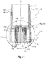
- FIG. 21 provides a cross-sectional view of a reusable dispenser comprising a tubular body, a telescopic actuator in a rest or collapsed state position; and a replaceable cartridge, according to one or more aspects;
- FIG. 21 A provides an enlarged view of an area within FIG. 21 ;
- FIG. 21 B provides an enlarged view of an area within FIG. 21 A , and provides a perspective, and transparent front view of a coupling sleeve of a tubular body in engagement with a lead screw, a tubular screw and an elevator being connected to each other in a rest or collapsed state position;
- FIG. 22 provides an exploded top view of a lead screw, a tubular screw and an elevator in disassembled form, according to one or more aspects
- FIG. 23 provides an exploded bottom view of a tubular screw and an elevator disassembled form, according to one or more aspects
- FIG. 24 depicts a schematic representation showing how the leading screw is inserted into the tubular screw, according to one or more aspects
- FIG. 25 depicts a schematic representation showing how the tubular screw is inserted into the elevator, according to one or more aspects
- FIG. 26 provides a perspective, front view of a lead screw, a tubular screw and an elevator when assembled in a collapsed state, according to one or more aspects
- FIG. 27 provides a cross-sectional view of a reusable dispenser comprising a tubular body, a telescopic actuator and a replaceable cartridge when the elevator is translated out from the tubular screw according to one or more aspects;
- FIG. 27 C provides a transparent side view of a coupling sleeve of a tubular body in engagement with a lead screw, a tubular screw and an elevator being connected to each other, when the elevator is translated out of the tubular screw according to one or more aspects;
- FIG. 27 E provides a perspective, and transparent front view of a coupling sleeve of a tubular body in engagement with a lead screw, a tubular screw and an elevator being connected to each other when the spokes of the tubular screw engage with the vertical grooves of the coupling sleeve according to one or more aspects;
- FIG. 28 provides a cross-sectional view of a reusable dispenser comprising a tubular body, a telescopic actuator and a replaceable cartridge when the tubular screw is translated out from the leading screw according to one or more aspects;
- FIG. 28 A provides a perspective, and transparent front view of an enlarged view of an area within FIG. 28 ;
- FIG. 29 B provides a front view a reusable dispenser of the dispensing package of FIG. 29 A , the reusable dispenser having a locking ring being inserted;
- FIG. 29 D provides a front view of a dispensing package for a spreadable personal care product shown in a closed position.
- Stress Sweep steady sweep
- Rheometer settings are initial stress (1.0 dyne/cm 2 ), final stress (63 930 dyne/cm 2 ), stress increment (100 dyne/cm 2 ), and maximum time per data point (5 seconds).
- an antiperspirant active such as an aluminum salt
- an antiperspirant active can react with the electrolytes in perspiration to form a plug in the ducts of sweat glands.
- the plugs prevent perspiration from exiting the duct, thereby depriving the bacteria of water and a food source.
- Antiperspirant compositions may be applied to the skin in a contact type antiperspirant product form, e.g., a stick or roll-on.
- deodorant product means a cosmetic composition applied topically at the underarm skin for minimizing malodors or unpleasant odors caused by the interaction of sebum, perspiration and bacteria on the underarm skin.
- anhydrous means that the cosmetic composition is preferably substantially or completely free of separately added water (i.e., anhydrous).
- structurant means any material known or otherwise effective in providing suspending, gelling, viscosifying, solidifying, and/or thickening properties to the composition or which otherwise provide structure to the final product form.
- substantially free of means less than 1%, less than 0.8%, less than 0.5%, less than 0.3%, or less than an immaterial amount of a stated ingredient by total weight of the specific component of the dispensing package, e.g. the replaceable cartridge.
- the longitudinal axis of the reusable dispenser, the replaceable cartridge and the telescopic actuator are coaxial with the longitudinal axis of the dispensing package. Any longitudinal axis herein is referenced with the letter “L”.
- the objects of the present invention are to provide dispensing packages for a spreadable personal care product, replaceable cartridges and reusable dispensers and methods for dispensing a spreadable personal care product as described in the Summary or as described hereinbelow for fulfilling the technical effects or goals as set out herein.
- a dispensing package 1 for a spreadable personal care product comprises: a reusable dispenser 3 , a replaceable cartridge 8 and optionally a top cap 2 .
- the telescopic actuator 5 is able to engage with the push plate 86 to deliver the spreadable personal care product from the open top 84 of the replaceable cartridge 8 .
- the locking ring 7 may comprise a first indicia 30 A located at an outer surface 78 of the locking ring 7 .
- the tubular body 6 may comprise a second indicia 30 B located at an outer surface 65 of the tubular body 6 .
- the first and second indicia ( 30 A, 30 B) may together form a final indicia 30 to indicate that the locking ring 7 is locked to the tubular body 6 of the reusable dispenser 3 .
- FIG. 1 provides a front view of a dispensing package for a spreadable personal care product shown and described herein in a closed position.
- a dispensing package 1 for a spreadable personal care product is shown and comprises a top cap 2 , a reusable dispenser 3 and a collar 4 .
- the reusable dispenser 3 comprising the tubular body 6 , the telescopic actuator 5 and optionally the locking ring 7 is designed to be durable and reusable.
- the replaceable cartridge 8 is designed to be disposable and non-durable or recyclable.
- a dispensing package 1 for a spreadable personal care product comprises: a reusable dispenser 3 and a replaceable cartridge 8 .
- the coupling sleeve 63 of the tubular body 6 may be integrally formed with the inner surface 68 of the tubular body 6 of the reusable dispenser 3 . In that case, the coupling sleeve 63 of the tubular body 6 protrudes from the inner surface 68 of the tubular body 6 of the reusable dispenser 3 .
- the reusable dispenser 3 also comprises a telescopic actuator 5 axially oriented within the tubular body 6 and mounted through the open bottom 62 of the tubular body 6 into the coupling sleeve 63 .
- the telescopic actuator 5 that allows delivering the spreadable personal care product from an open top 84 of the replaceable cartridge 8 will be described in more details hereinafter.
- the replaceable cartridge 8 comprises a tubular chamber 80 for holding the spreadable personal care product.
- the replaceable cartridge 8 comprises a tubular chamber 80 that at least partially surrounds and supports a spreadable personal care product.
- the tubular chamber 80 includes an open top 84 and an open bottom 85 .
- the replaceable cartridge 8 comprises an upper end 81 at the open top 84 of the replaceable cartridge 8 and a lower end 82 at the open bottom 85 of the replaceable cartridge 8 , the lower end 82 being opposed to the upper end 81 of the replaceable cartridge 8 .
- the tubular chamber 80 of the replaceable cartridge 8 comprises a side wall 83 having an inner surface 87 and an outer surface 88 .
- the tubular chamber 80 comprises a push plate 86 disposed inside the tubular chamber 80 at or adjacent to the open bottom 85 of the tubular chamber 80 .
- the push plate 86 of the replaceable cartridge 8 comprises a top surface 860 and a bottom surface 864 .
- the tubular chamber 80 of the replaceable cartridge 8 is also not limited to a cylindrical chamber.
- the tubular chamber 80 of the replaceable cartridge 8 has an outer shape defined by the outer surface 88 of the replaceable cartridge 8 .
- the tubular chamber 80 of the replaceable cartridge 8 has an inner shape defined by the inner surface 87 of the replaceable cartridge 8 .
- Examples of such “generally cylindrical” and “generally conical” or “generally elliptical” tubular chamber 80 of the replaceable cartridge 8 may include, without limitation, the tubular chamber 80 of the replaceable cartridge 8 having a cross-sectional shape deviating from circular by being elongated in a direction transverse to the longitudinal axis L of the replaceable cartridge 8 , e.g., elliptical, oval, and the like.
- the tubular chamber 80 of the replaceable cartridge 8 may have other suitable shapes as well, e.g., polygonal, rectangular prism, cuboid, and so on or a combination of generally cylindrical/conical and polygon
- the replaceable cartridge 8 may be disposable and recyclable.
- the replaceable cartridge 8 may be made of a sustainable material selected from the group consisting of a recycled material and a renewable material.
- the replaceable cartridge 8 may be substantially free, or free of a plastic polymeric material selected from the group consisting of polyethylene, polypropylene, polyethylene terephthalate, polyester, polyamide, polystyrene, polyvinyl chloride, and mixtures thereof.
- the replaceable cartridge 8 may be made of cellulosic fiber which are natural fibers such as typically wood pulp fibers.
- Applicable wood pulps include chemical pulps, such as Kraft, sulfite, and sulfate pulps, as well as mechanical pulps including, for example, groundwood, thermomechanical pulp and chemically modified thermomechanical pulp.
- Pulps derived from both deciduous trees (hereinafter, also referred to as “hardwood”) and coniferous trees (hereinafter, also referred to as “softwood”) may be utilized.
- the hardwood and softwood fibers can be blended, or alternatively, can be deposited in layers to provide a stratified web.
- the replaceable cartridge 8 may be made from a molded paper web into a tubular shape.
- a paper web may be made by a process comprising the steps of forming an aqueous papermaking furnish, depositing this furnish on a foraminous surface, such as a Fourdrinier wire, and removing the water from the furnish as by gravity or vacuum-assisted drainage, with or without pressing, and by evaporation, comprising the final steps of adhering the sheet in a semi-dry condition to the surface of a Yankee dryer, completing the water removal by evaporation to an essentially dry condition, removal of the web from the Yankee dryer by means of a flexible creping blade, and winding the resultant sheet onto a reel.
- the replaceable cartridge 8 may be provided in different variants.
- the upper end 81 of the replaceable cartridge 8 may have a sharped edge 840 and the lower end 82 of the replaceable cartridge 8 may have a rounded edge 850 , as shown for instance FIG. 7 and FIG. 8 .
- the replaceable cartridge 8 may be made of a spiral wounded tube.
- the replaceable cartridge 8 may include a first laminate 80 A forming an outer part of the tubular chamber 80 and the rounded edge 850 at the open bottom 85 of the replaceable cartridge 8 , as shown for instance in FIG. 9 .
- the replaceable cartridge 8 may be made of a spiral wounded tube.
- the replaceable cartridge 8 may include a first laminate 80 A forming an inner part of the tubular chamber 80 and the rounded edge 850 at the open bottom 85 of the replaceable cartridge 8 .
- the replaceable cartridge 8 may comprise a second laminate 80 B forming an outer part of the tubular chamber 80 and the rounded edge 845 at the open top 84 of the replaceable cartridge 8 , as shown for instance in FIG. 12 .
- the inner surface 87 of the tubular chamber 80 of the replaceable cartridge 8 may comprise a suitable impermeable and/or anti-adhesive coating.
- Such impermeable and/or anti-adhesive coating can help for preventing the spreadable personal care product from sticking at the inner surface 87 of the tubular chamber 80 .
- Such anti-adhesive coating may be preferred when the replaceable cartridge 8 is made of paper. Indeed, when the replaceable cartridge 8 is made of paper, the paper material might adhere to the spreadable personal care product because on a micro scale, the spreadable personal care product might penetrate the pores of the paper material.
- the personal care product can slide readily out from the replaceable cartridge 8 , when the push plate 86 moves upwardly towards the open top 84 of the replaceable cartridge 8 .
- the push plate 86 of the replaceable cartridge 8 may comprise first, second and third layers ( 861 , 862 , 863 ).
- the first layer 861 of the push plate 86 is positioned towards the open top 84 of the replaceable cartridge 8 .
- the third layer 863 of the push plate 86 is positioned towards the open bottom 85 of the replaceable cartridge 8 .
- the second layer 862 of the push plate 86 is positioned between the first and third layer ( 861 , 863 ) of the push plate 86 .
- FIG. 10 provides a cross-sectional view of a replaceable cartridge 8 comprising a push plate 86 including first, second and third layers ( 861 , 862 , 863 ) when the upper end 81 of the replaceable cartridge 8 may have a sharped edge 840 .
- FIG. 12 provides a cross-sectional view of another replaceable cartridge 8 comprising a push plate 86 including first, second and third layers ( 861 , 862 , 863 ) when the upper end 81 of the replaceable cartridge 8 may have a rounded edge 845 .
- the reusable dispenser 3 may comprise a locking ring 7 removably engaged with the tubular body 6 of the reusable dispenser 3 to secure the replaceable cartridge 8 within the tubular body 6 of the reusable dispenser 3 .
- the locking ring 7 may comprise an upper end 72 at an open top 71 , a lower end 74 at an open bottom 73 , an inner surface 76 and an outer surface 78 .
- the lower end 74 of the locking ring 7 is opposed to the upper end 72 of the locking ring 7 .
- the locking ring 7 may comprise an inner shape defined by the inner surface 76 of the locking ring 7 .
- the locking ring 7 may comprise an outer shape defined by the outer surface 78 of the locking ring 7 .
- FIG. 13 and FIG. 16 provide front perspective views of two non-limiting examples of a locking ring 7 within the present disclosure.
- the locking ring 7 shall not be limited to a cylindrical ring.
- the locking ring 7 may have any suitable outer shape, including, e.g., a generally cylindrical shape, a generally conical shape, a generally elliptical shape, or any combination thereof.
- Examples of such “generally cylindrical” and “generally conical” or “generally elliptical” locking ring 7 may include, without limitation, the locking ring 7 having a cross-sectional shape deviating from circular by being elongated in a direction transverse to the longitudinal axis L of the locking ring 7 , e.g., elliptical, oval, and the like.
- the locking ring 7 may have other suitable shapes as well, e.g., polygonal, rectangular prism, cuboid, and so on or a combination of generally cylindrical/conical and polygonal shapes.
- the locking ring 7 may comprise a circumferential edge 75 located at the upper end 72 of the locking ring 7 .
- the circumferential edge 75 protrudes from the inner surface 76 of the locking ring 7 .
- the locking ring 7 may secure the replaceable cartridge 8 within the tubular body 6 of the reusable dispenser 3 by contacting the inner surface 76 of the locking ring 7 with the outer surface 88 of the replaceable cartridge 8 .
- the locking ring 7 may secure the replaceable cartridge 8 within the tubular body 6 of the reusable dispenser 3 by abutting the circumferential edge 75 of the locking ring 7 with the upper end 81 of the replaceable cartridge 8 , i.e. the sharped edge 840 or the rounded edge 845 at the open top 84 of the replaceable cartridge 8 .
- the locking ring 7 may secure the replaceable cartridge 8 within the tubular body 6 of the reusable dispenser 3 by abutting a bottom of the circumferential edge 75 of the locking ring 7 with the upper end 81 of the replaceable cartridge 8 , i.e. the sharped edge 840 or the rounded edge 845 at the open top 84 of the replaceable cartridge 8 .
- the replaceable cartridge 8 may have a height Hc as measured in a direction parallel along the longitudinal axis L from the upper end 81 of the replaceable cartridge 8 to the lower end 82 of the replaceable cartridge 8 (See for instance, FIG. 3 ).
- the height Hc of the replaceable cartridge 8 may be equal to an height of an upper portion of the reusable dispenser 3 as measured in a direction parallel along the longitudinal axis L from a bottom of the circumferential edge 75 of the locking ring 7 to a lower end 66 A of the upper top portion 66 of the tubular body 6 .
- the dimensions of the tubular chamber 80 of the replaceable cartridge 8 and the locking ring 7 may also be adjusted.
- the open top 71 of the locking ring 7 may have an inner diameter d 1 .
- the inner diameter d 1 may be measured diametrically in a transversal direction perpendicular to a longitudinal axis L of the locking ring 7 .
- the longitudinal axis L of the locking ring 7 is coaxial with the longitudinal axis L of the reusable dispenser 3 .
- the open top 71 of the locking ring 7 may be defined by the circumferential edge 75 of the locking ring 7 .
- the circumferential edge 75 of the locking ring 7 may have an inner surface 750 .
- the inner diameter d 1 may be thus measured from two points diametrically opposed on the inner surface 750 of the circumferential edge 75 of the locking ring 7 in a transversal direction perpendicular to the longitudinal axis L of the locking ring 7 , as shown for instance in FIG. 14 .
- the open top 84 of tubular chamber 80 of the replaceable cartridge 8 may have an inner diameter D 1 and an outer diameter D 2 .
- the inner diameter D 1 of the open top 84 of the tubular chamber 80 of the replaceable cartridge 8 may be measured from two points diametrically opposed at the inner surface 87 of the tubular chamber 80 in a transversal direction perpendicular to the longitudinal axis L of the replaceable cartridge 8 , as shown for instance in FIGS. 8 and 10 .
- the outer diameter D 2 of the open top 84 of the tubular chamber 80 of the replaceable cartridge 8 may be measured from two points diametrically opposed and each point being located on respective tangents of the rounded edge 845 of the upper end 81 of the replaceable cartridge 8 .
- Each tangent meets the outer surface 88 of the replaceable cartridge 8 at the rounded edge 845 of the replaceable cartridge 8 .
- Each tangent is also parallel to the longitudinal axis L of the replaceable cartridge 8 .
- the outer diameter D 2 of the open top 84 of the tubular chamber 80 of the replaceable cartridge 8 may be measured from two points diametrically opposed and each point being located on the respective tangent in a transversal direction perpendicular to the longitudinal axis L of the replaceable cartridge 8 , as shown in FIG. 12 .
- the inner diameter D 1 of the open top 84 of the tubular chamber 80 of the replaceable cartridge 8 may be measured from two points diametrically opposed and each point being located on respective tangents of the rounded edge 845 of the upper end 81 of the replaceable cartridge 8 .
- Each tangent is located inside the tubular chamber 80 of the replaceable cartridge 8 at the rounded edge 845 of the replaceable cartridge 8 .
- Each tangent is also parallel to the longitudinal axis L of the replaceable cartridge 8 .
- the outer diameter D 2 of the open top 84 of the tubular chamber 80 of the replaceable cartridge 8 may be measured from two points diametrically opposed and each point being located on the respective tangent in a transversal direction perpendicular to the longitudinal axis L of the replaceable cartridge 8 , as shown in FIG. 12 .
- the inner diameter d 1 of the open top 71 of the locking ring 7 may be smaller than the outer diameter D 2 of the open top 84 of the replaceable cartridge 8 . Also, the inner diameter d 1 of the open top 71 of the locking ring 7 may be greater than the inner diameter D 1 of the open top 84 of the replaceable cartridge 8 .
- the inner diameter d 1 of the open top 71 of the locking ring 7 may be smaller than the outer diameter D 2 of the open top 84 of the replaceable cartridge 8 . Also, the inner diameter d 1 of the open top 71 of the locking ring 7 may be smaller than the inner diameter D 1 of the open top 84 of the replaceable cartridge 8 , in order to control the opening of the locking ring 7 to control the topical application of the personal care product.
- the locking ring 7 may for instance, have an apertured dome shape to assist the topical application of the personal care product to the skin.
- the size of the apertured dome shape may be thus controlled by the inner diameter d 1 of the open top 71 of the locking ring 7 .
- the locking ring 7 can be removably engaged with the tubular body 6 of the reusable dispenser 3 to secure the replaceable cartridge 8 within the tubular body 6 of the reusable dispenser 3 in different ways.
- FIG. 13 provides a front perspective view of a locking ring 7 comprising an annular groove 77 located at the open bottom 73 of the locking ring 7 .
- FIG. 14 provides a bottom view of the locking ring of FIG. 13 .
- the annular groove 77 of the locking ring 7 has an inner surface 770 .
- the annular groove 77 may comprise one or more engagement members, namely one or more male lugs 771 which protrude from the inner surface 770 of the annular groove 77 of the locking ring 7 .
- the one or more male lugs 771 of the annular groove 77 of the locking ring 7 can be seen as interlocking protrusions or bayonet lugs.
- the one or more male lugs 771 of the annular groove 77 of the locking ring 7 may be located at or adjacent to the open bottom 73 of the locking ring 7 or the lower end 74 of the locking ring 7 .
- the annular groove 77 may comprise four male lugs 771 which protrude from the inner surface 770 of the annular groove 77 of the locking ring 7 , such that two adjacent male lugs 771 of the annular groove 77 are positioned at an angle of ⁇ /2 relative to the longitudinal axis L of the locking ring 7 , as shown for instance in FIGS. 13 and 14 .
- the one or more male lugs 771 of the annular groove 77 of the locking ring 7 may also be located at or adjacent to the open bottom 73 of the locking ring 7 and on the same circular plane orthogonal to the longitudinal axis L of the locking ring 7 .
- the tubular body 6 of the reusable dispenser 3 may be adapted to engage with the one or more male lugs 771 of the annular groove 77 of the locking ring 7 .
- the stepped section 600 may comprise two interlocking recesses 601 .
- the two interlocking recesses 601 of the stepped section 600 may be diametrically opposed in a transversal direction perpendicular to the longitudinal axis L of the reusable dispenser 3 .
- the stepped section 600 may comprise four interlocking recesses 601 such that two adjacent interlocking recesses 601 of the stepped section 600 may be positioned at an angle of ⁇ /2 relative to the longitudinal axis L of the reusable dispenser 3 , as shown for instance in FIG. 15 .
- the locking ring 7 may engage with the tubular body 6 of the reusable dispenser 3 .
- the one or more male lugs 771 of the annular groove 77 of the locking ring 7 snap fit over the one or more interlocking recesses 601 of the stepped section 600 to engage the locking ring 7 with the tubular body 6 for securing the replaceable cartridge 8 within the tubular body 6 of the reusable dispenser 3 .
- the one or more interlocking recesses 601 of the stepped section 600 are designed to allow access of the one or more male lugs 771 of the annular groove 77 of the locking ring 7 , when the locking ring 7 is inserted from above at the open top 61 of the tubular body 6 of the reusable dispenser 3 .
- a clockwise rotation of the locking ring 7 can help for locking the one or more male lugs 771 of the annular groove 77 of the locking ring 7 into the respective one or more interlocking recesses 601 of the stepped section 600 ; and preventing any axial movement of the locking ring 7 relative to the tubular body 6 of the reusable dispenser 3 .
- the locking ring 7 When the locking ring 7 needs to be removed (typically when the replaceable cartridge 8 is empty and requires replacing), the locking ring 7 is rotated counter-clockwise and the one or more male lugs 771 of the annular groove 77 of the locking ring 7 may then be lifted clear of the respective one or more interlocking recesses 601 of the stepped section 600 .
- replaceable cartridge 8 that will be discarded or recycled is provided as simple as is practicable without no additional locking means to be included on it.
- the replaceable cartridge 8 without any interlocking mean features comprise less material to be discarded or recycled.
- the replaceable cartridge 8 with a sustainable material, such as the ones described more in details above, e.g. paper, corrugated paperboard, cardboard, cork or mixtures thereof, which helps to significantly reduce the consumption of non-renewable resources.
- a sustainable material such as the ones described more in details above, e.g. paper, corrugated paperboard, cardboard, cork or mixtures thereof, which helps to significantly reduce the consumption of non-renewable resources.
- the one or more male lugs 771 of the annular groove 77 of the locking ring 7 may have a L-shape.
- the one or more interlocking recesses 601 of the stepped section 600 may have a L-shape corresponding to the L-shape of the one or more male lugs 771 of the annular groove 77 of the locking ring 7 . In that case, the one or more male lugs 771 of the annular groove 77 of the locking ring 7 come up against the one or more interlocking recesses 601 of the stepped section 600 .
- annular groove 77 of the locking ring 7 may comprise inner threads 772 as shown for instance in FIG. 16 .
- the tubular body 6 of the reusable dispenser 3 may be adapted to engage with the inner threads 772 of the annular groove 77 of the locking ring 7 .
- replaceable cartridge 8 with any locking means for releasably securing the replaceable cartridge 8 within the tubular body 6 of the reusable dispenser 3 .
- the replaceable cartridge 8 that will be discarded or recycled is provided as simple as is practicable without no additional means to be included on it.
- the replaceable cartridge 8 without any outer thread features comprise less material to be discarded or recycled.
- the replaceable cartridge 8 without any locking means can be readily inserted into or removed from the reusable dispenser 3 without having to manipulate the replaceable cartridge 8 itself to fix or detach it from the tubular body 6 of the reusable dispenser 3 .
- the reusable dispenser 3 may not comprise any holder to support or to attach the replaceable cartridge 8 with the tubular body 6 .
- the replaceable cartridge 8 can be maintained in place within the tubular body 6 of the reusable dispenser 3 because of the attachment of the removable locking ring 7 to the tubular body 6 , especially when the circumferential edge 75 of the locking ring 7 abuts the upper end 81 of the replaceable cartridge 8 .
- the upper end 72 of the locking ring 7 and the circumferential edge 75 of the locking ring 7 together form a curvature including, but not limited to, convex, concave, or a mixture thereof, in some examples the upper end 72 of the locking string 7 may be convex, in the cross section, in a transverse direction perpendicular to the longitudinal axis L of the locking ring 7 .
- the reusable dispenser 3 may comprise a perforated dome cover 9 .
- the open top 71 of the locking ring 7 may optionally comprise an upwardly facing perforated dome cover 9 , as shown for instance in FIGS. 18 , 19 and 20 .
- the perforated dome cover 9 may be a separate member that is formed separately and then attached to the locking ring 7 (by any conventional means immediately apparent to the skilled person).
- FIG. 18 provides a front perspective view of a perforated dome cover 9 as a separate member from the locking ring 7 .
- the perforated dome cover 9 may be integrally formed with the locking ring 7 .
- FIGS. 19 and 20 provide front perspective views of perforated dome covers 9 integrally formed with the locking ring 7 .
- the perforated dome cover 9 is generally useful for personal care products with rheology, hardness, and/or melting profiles that are considered gels or semi-solids.
- soft solids are described in U.S. Patent Publication No. 2013/0108570A1 whereby the rheology profile may include a combination of product hardness in the form of penetration force (gram-force), static yield stress (Pa) values, and/or high shear stress viscosity via methods for determining such characteristics of the rheology profile that are described therein.
- the perforated dome cover 9 may extend outwardly from and completely surround a periphery of the open top 71 of the locking ring 7 .
- the upper end 72 of the locking ring 7 and/or perforated dome cover 9 may comprise a curvature including, but not limited to, convex, concave or a mixture thereof, in some examples the curvature can be convex, in the cross section, in a transverse direction perpendicular to the longitudinal axis L of the locking ring 7 .
- the perforated dome cover 9 may comprise a plurality of apertures.
- the apertures in the perforated dome cover 9 may represent from 15% to 80%, or from 30% to 60%, or from 39% to 50%, of a surface area of the perforated dome cover 9 .
- the surface area of the perforated dome cover 9 may correspond to the surface area as measured from a topographical view of the perforated dome cover 9 .
- the perforated dome cover 9 may comprise a convex configuration.
- the convex configuration of the perforated dome cover 9 may have a radius of curvature of from about 25 mm to about 127 mm, alternatively from about 57 mm to about 69 mm, for a major dimension.
- the convex configuration of the perforated dome cover 9 may have a radius of curvature of from about 12 mm to about 39 mm, alternatively from about 22 mm to about 28 mm for a minor dimension.
- the average aperture area of the perforated dome cover 9 may range from 0.12 cm 2 to 0.50 cm 2 , alternatively from about 0.2 cm 2 to about 0.35 cm 2 .
- the perforated dome cover 9 may comprise a plurality of apertures ( 91 , 92 ). wherein each of the plurality of apertures has a circular or noncircular shape.
- a noncircular shape may be polygonal, trapezoidal, or parallelepipedal.
- FIG. 19 and FIG. 20 illustrate some non-limiting perforated dome covers 9 comprising a plurality of apertures having different shapes.
- the apertures 91 of the perforated dome cover 9 may have a circular shape.
- the apertures 91 of the perforated dome cover 9 may have an average circular diameter of from about 1.9 mm to about 2.6 mm.
- the perforated dome cover thickness may be from about 0.25 mm to about 1.53 mm, alternatively from about 0.45 mm to about 1.1 mm.
- the perforated dome cover 9 may have a bottom edge closest to the open top 61 of the tubular body 6 of the reusable dispenser 3 and the open top 84 of the replaceable cartridge 8 . Also, the perforated dome cover 9 may have a top edge 93 , furthest or distal from the open top 61 of the tubular body 6 of the reusable dispenser 3 and the open top 84 of the replaceable cartridge 8 .
- the top edge 93 of the perforated dome cover 9 can help to provide a surface for applying the spreadable personal care product.
- the outer surface of the perforated dome cover 9 can aid in applying, dosing, and/or delivering the desired amount of the spreadable personal care product to the skin being taking care, and may, in addition to having a plurality of apertures, be smooth or textured.
- Textured applicator surfaces include, but are not limited to dimpling, bumping, electrical discharge machining (EDM), coating, emboss, deboss or mixtures thereof.
- the locking ring 7 may comprise a first indicia 30 A located at the outer surface 78 of the locking ring 7 .
- the tubular body 6 may comprise a second indicia 30 B located at the outer surface 65 of the tubular body 6 .
- the first and second indicia ( 30 A, 30 B) may together form a final indicia 30 to indicate that the locking ring 7 is locked to the tubular body 6 of the reusable dispenser 3 .
- the first and second indicia ( 30 A, 30 B) may join together to form the final indicia 30 to indicate that the locking ring 7 is locked to the tubular body 6 of the reusable dispenser 3 .
- the first and second indicia ( 30 A, 30 B) may be connected together to form the final indicia 30 , which provides the secured information that the replaceable cartridge 8 is locked in place within the tubular body 6 .
- FIG. 2 provides a front view of a dispensing package 1 for a spreadable personal care product in an open position.
- the reusable dispenser 3 is in a closed position since the locking ring 7 has been attached to the tubular body 6 of the reusable dispenser 3 . In such closed position, the consumer is ensured that the locking ring 7 is well secured onto the tubular body 6 because the first indicia 30 A located at the outer surface 78 of the locking ring 7 and the second indicia 30 B located at the outer surface 65 of the tubular body 6 together form a final indicia 30 .
- the first and second indicia ( 30 A, 30 B) of the reusable dispenser 3 may be the same or different from one another.
- an indicia may be any type of lines, patterns, ornamental designs, symbols, script, color codes, or other markings which have the capability, either inherently or with additional denotation, to aid an individual securing the replaceable cartridge 8 within the reusable dispenser 3 by indicating the locking ring 7 is locked to the tubular body 6 of the reusable dispenser 3 .
- the first and second indicia ( 30 A, 30 B) of the reusable dispenser 3 may also or alternatively include, but are not limited to, pressure sensitive labels; shrink wrap labels; or other visually detectable or discernable aspects (e.g., “sparkles” or “glitter” via incorporation of interference pigments) that are part of the material from which the tubular body 6 or the locking ring 7 are made or that is subsequently added to the manufactured components; defined relief, indentation, windows and/or gaps formed in the components during or after their manufacture; cast designs, including but not limited to novelty casting to identify characters, paraphernalia, animals, and the like; particular shapes or other means of decoration and/or information sharing used to indicate to the individual that the locking ring 7 is locked to the tubular body 6 of the reusable dispenser 3 .
- the first and second indicia ( 30 A, 30 B) and/or the final indicia 30 of the reusable dispenser 3 may comprise a shape and/or a surface feature, etc.
- the locking ring 7 may comprise a first indicia 30 A located at the outer surface 78 of the locking ring 7 .
- the tubular body 6 may comprise a second indicia 30 B located at the outer surface 65 of the tubular body 6 .
- the first indicia 30 A located at the outer surface 78 of the locking ring 7 may have a visual appearance that is transparent, translucent or substantially opaque, or include a portion of the same.
- the second indicia 30 B located at the outer surface 65 of the tubular body 6 may have a visual appearance that is transparent, translucent or substantially opaque, or include a portion of the same.
- the first and second indicia ( 30 A, 30 B) and the resulting indicia 30 may comprise a particular shape including, but not limited to, circle, square, rectangle, oval, star, heart, diamond, polygons and the like.
- the first and second indicia ( 30 A, 30 B) and the resulting final indicia 30 may define a window to discern the outer surface 88 of the replaceable cartridge 8 .
- the first indicia 30 A of the locking ring 7 may be positioned at a location at or adjacent the open bottom 73 of the locking ring 7 and at the outer surface 78 of the locking ring 7 .
- the second indicia 30 B of the tubular body 6 of the reusable dispenser 3 may be positioned at a location at or adjacent the open top 61 of the tubular body 6 and at the outer surface 65 of the tubular body 6 .
- the locking ring 7 may engage with the tubular body 6 of the reusable dispenser 3 .
- the one or more male lugs 771 of the annular groove 77 of the locking ring 7 may snap fit over the one or more interlocking recesses 601 of the stepped section 600 to engage the locking ring 7 with the tubular body 6 for securing the replaceable cartridge 8 within the tubular body 6 of the reusable dispenser 3 .
- the first indicia 30 A of the locking ring 7 may be positioned at a location at or adjacent the open bottom 73 of the locking ring 7 ; and at a male lug 771 and at the outer surface 78 of the locking ring 7 .
- the second indicia 30 B of the tubular body 6 of the reusable dispenser 3 may be positioned at a location at or adjacent the stepped section 600 of the tubular body 6 , and at an interlocking recess 601 of the stepped section 600 of the tubular body 6 , wherein the interlocking recesses 601 of the stepped section 600 has a L-shape. All the interlocking recesses 601 of the stepped section 600 may have a L-shape, as shown for instance in FIGS. 13 and 15 .
- the first and second indicia may together form a final indicia 30 to indicate that the locking ring 7 is locked to the tubular body 6 of the reusable dispenser 3 when the one or more male lugs 771 of the annular groove 77 of the locking ring 7 snap fit over the one or more interlocking recesses 601 of the stepped section 600 .
- the first indicia 30 A of the locking ring 7 positioned at a location at a male lug 771 of the locking ring 7 meet the second indicia 30 B of the tubular body 6 positioned at a location at the interlocking recesses 601 being in L-shape. All the interlocking recesses 601 of the stepped section 600 may have a L-shape.
- the first indicia 30 A of the locking ring 7 may be positioned at a location at or adjacent to the open bottom 73 of the locking ring 7 ; and adjacent to a male lug 771 and at the outer surface 78 of the locking ring 7 .
- the second indicia 30 B of the tubular body 6 of the reusable dispenser 3 may be positioned at a location at or adjacent to the stepped section 600 of the tubular body 6 , and adjacent to an interlocking recesses 601 of the stepped section 600 of the tubular body 6 , wherein the interlocking recesses 601 of the stepped section 600 has a L-shape.
- the first and second indicia may together form a final indicia 30 to indicate that the locking ring 7 is locked to the tubular body 6 of the reusable dispenser 3 when the one or more male lugs 771 of the annular groove 77 of the locking ring 7 snap fit over the one or more interlocking recesses 601 of the stepped section 600 .
- the first indicia 30 A of the locking ring 7 positioned at a location adjacent to a male lug 771 at the outer surface 78 of the locking ring 7 meet the second indicia 30 B of the tubular body 6 positioned at a location adjacent to an interlocking recesses 601 being in L-shape.
- the first indicia 30 A of the locking ring 7 may be positioned at a location at or adjacent to the open bottom 73 of the locking ring 7 ; and adjacent to the start of the inner threads 772 of the annular groove 77 .
- the second indicia 30 B of the tubular body 6 of the reusable dispenser 3 may be positioned at a location at or adjacent to the stepped section 600 of the tubular body 6 , and adjacent to the start of the outer threads 602 of the stepped section 600 .
- the first and second indicia may together form a final indicia 30 to indicate that the locking ring 7 is locked to the tubular body 6 of the reusable dispenser 3 when the inner threads 772 of the annular groove 77 engage completely with the outer threads 602 of the stepped section 600 .
- the dispensing package 1 for a spreadable personal care product may comprise optionally a top cap 2 .
- the top cap 2 of the dispensing packaging 1 can be relatively short in height relatively to the height of the reusable dispenser 3 with regard to the longitudinal axis L.
- the top cap 2 of the dispensing packaging 1 may cover only the locking ring 7 , and optionally the perforated dome cover 9 as described hereinbefore.
- the top cap 2 of the dispensing packaging 1 may cover the tubular body 6 of the reusable dispenser 3 and rest on the collar 4 of the reusable dispenser 3 .
- the top cap 2 of the reusable dispenser 3 can cover the reusable dispenser 3 , the open top 84 of replaceable cartridge 8 ; the tubular body 6 of the reusable dispenser 3 between uses; optionally the locking ring 7 and optionally the perforated dome cover 9 .
- the top cap 2 of the reusable dispenser 3 may assist to avoid contamination of the spreadable personal care product and the locking ring 7 by any foreign matter, such as dust, when the dispensing package 1 is not being used.
- the top cap 2 of the reusable dispenser 3 may comprise one or more engagement members included in the top cap 2 .
- the collar 4 or the tubular body 6 of the reusable dispenser 3 may also releasably engage the top cap 2 , thereby to enable top cap 2 to detachably cover the reusable dispenser 3 .
- the telescopic actuator 5 comprises a hand wheel 51 , a central shaft 52 , a leading screw 53 , a tubular screw 54 and an elevator 55 , as shown for instance in FIG. 3 and FIG. 21 .
- FIG. 3 provides a cross-sectional view of a reusable dispenser 3 comprising a tubular body 6 and a telescopic actuator 5 with a replaceable cartridge 8 locked into the tubular body 6 of the reusable dispenser 3 .
- FIG. 21 provides a cross-sectional view of a reusable dispenser 3 comprising a tubular body 6 and a telescopic actuator 5 with a replaceable cartridge 8 that has been slidingly mounted through the open top 61 of the tubular body 6 .
- the telescopic actuator 5 comprises a hand wheel 51 having an inner surface 512 and a perimeter wall 510 .
- the perimeter wall 510 of the telescopic actuator 5 extends around the lower bottom portion 67 of the tubular body 6 .
- the hand wheel 51 of the telescopic actuator 5 has a bottom 513 having an inner surface 5130 .
- the telescopic actuator 5 additionally comprises a central shaft 52 connected to the hand wheel 51 of the telescopic actuator 5 .
- the central shaft 52 of the telescopic actuator 5 extends from the inner surface 5130 of the bottom 513 of the hand wheel 51 into the coupling sleeve 63 of the tubular body 6 along the longitudinal axis L.
- the central shaft 52 of the telescopic actuator 5 comprises an upper end 520 .
- the central shaft 52 comprises a leading screw 53 located at the upper end 520 of the central shaft 52 .
- the leading screw 53 may be a separate member that is formed separately and then attached to the central shaft 52 of the telescopic actuator 5 .
- the leading screw 53 may be integrally formed with the central shaft 52 of the telescopic actuator 5 .
- the telescopic actuator 5 comprises a leading screw 53 , a tubular screw 54 and an elevator 55 . Each segment of the telescopic actuator 5 and how they are connected will be described more in details.
- FIG. 22 provides an exploded top view of a lead screw 53 , a tubular screw 54 and an elevator 55 in disassembled form.
- the leading screw 53 comprises an upper end 530 and a lower end 531 opposed to the upper end 530 of the leading screw 53 .
- the leading screw 53 comprises a side wall 534 having an inner surface 535 and an outer surface 536 .
- the leading screw 53 may have a cylindrical outer shape.
- the leading screw 53 further comprises first and second opposed outer threads ( 532 , 533 ) located at or adjacent to the upper end 530 of the leading screw 53 .
- the leading screw 53 may have a cavity 537 that can engage with the central shaft 52 for attaching the leading screw 53 and the central shaft 52 together.
- the leading screw 53 may have a hexagonal cavity 537 that can engage with a corresponding hexagonal central shaft 52 (not represented) for attaching the leading screw 53 and the central shaft 52 together.
- the leading screw 53 may have a cavity that can engage with the central shaft 52 for attaching the leading screw 53 and the central shaft 52 together, wherein the cavity of the leading screw 53 has a shape which is selected from the group consisting of round, oval, square, hexagonal and triangular.
- the open top 540 , the open bottom 541 and the side wall 548 of the tubular screw 54 define a threaded cavity.
- the threaded cavity of the tubular screw 54 have double start inner threads 542 including two opposed lower thread stops 5420 .
- the double start inner threads 542 of the tubular screw 54 extend from the open top 540 of the tubular screw 54 to a distal position of the open bottom 541 of the tubular screw 54 , until the respective two opposed lower thread stops 5420 of the tubular screw 54 , as shown in FIG. 23 .
- the tubular screw 54 also comprises first and second opposed outer threads ( 543 , 544 ) located at or adjacent to the upper end 545 of the tubular screw 54 .
- the tubular screw 54 of the telescopic actuator 5 additionally comprises an annular ring 5460 protruding from the outer surface 549 A of the tubular screw 54 and located at the lower end 547 of the tubular screw 54 .
- the tubular screw 54 comprises two or more spokes 546 located at the lower end 547 of the tubular screw 54 .
- the two or more spokes 546 protrude from an outer surface of the annular ring 5460 in a direction perpendicular to the longitudinal axis L.
- the tubular screw 54 of the telescopic actuator 5 may comprise two spokes 546 positioned at an angle of ⁇ from each other with regard to the longitudinal axis L, alternatively four spokes 546 positioned at an angle of ⁇ /2 from each other with regard to the longitudinal axis L.
- the telescopic actuator 5 further comprises an elevator 55 .
- the elevator 55 of the telescopic actuator 5 comprises a side wall 554 having an outer surface 555 and an inner surface 556 .
- the elevator 55 of the telescopic actuator 5 includes an upper end 557 and a lower end 558 opposed to the upper end 557 of the elevator 55 .
- the elevator 55 of the telescopic actuator 5 includes a closed top 550 at the upper end 557 of the elevator 55 and an open bottom 551 at the lower end 558 of the elevator 55 .
- the closed top 550 of the elevator 55 has a top surface 559 .
- the closed top 550 , the open bottom 551 and the side wall 554 of the elevator 55 define a threaded cavity.
- the threaded cavity of the elevator 55 have double start inner threads 552 including two opposed lower thread stops 5520 .
- the double start inner threads 552 of the elevator 55 extend from the closed top 550 of the elevator 55 to a distal position of the open bottom 551 of the elevator 55 , until the respective two opposed lower thread stops 5520 of the elevator 55 , as shown for instance in FIG. 23 .
- the leading screw 53 , the tubular screw 54 and the elevator 55 of the telescopic actuator 5 are engaged as follows, as illustrated for instance with FIGS. 24 - 26 .
- the leading screw 53 of the telescopic actuator 5 is permanently and threadedly engaged with the tubular screw 54 of the telescopic actuator 5 by engaging the first and second opposed outer threads ( 532 , 533 ) of the leading screw 53 with the double start inner threads 542 of the tubular screw 54 .
- the double start inner threads 542 of the tubular screw 54 extend from the open top 540 of the tubular screw 54 to a distal position of the open bottom 541 of the tubular screw 54 until the respective two opposed lower thread stops 5420 of the tubular screw 54 such that the leading screw 53 and the tubular screw 54 do not detach.
- first and second opposed outer threads ( 532 , 533 ) of the leading screw 53 are captured within the double start inner threads 542 of the tubular screw 54 .
- the first and second opposed outer threads ( 532 , 533 ) of the leading screw 53 and the double start inner threads 542 of the tubular screw 54 together in engagement cannot be disconnected.
- the tubular screw 54 translates out of the leading screw 53
- the first and second opposed outer threads ( 532 , 533 ) of the leading screw 53 will move until abutting the respective two opposed lower thread stops 5420 of the tubular screw 54 .
- the tubular screw 54 of the telescopic actuator 5 is permanently and threadedly engaged with the elevator 55 of the telescopic actuator 5 by engaging the first and second opposed outer threads ( 543 , 544 ) of the tubular screw 54 with the double start inner threads 552 of the elevator 55 .
- the double start inner threads 552 of the elevator 55 extend from the closed top 550 of the elevator 55 to a distal position of the open bottom 551 of the elevator 55 until the respective two opposed lower thread stops 5520 of the elevator 55 , such that the tubular screw 54 and the elevator 55 do not detach.
- first and second opposed outer threads ( 543 , 544 ) of the tubular screw 54 are captured within the double start inner threads 552 of the elevator 55 .
- the first and second opposed outer threads ( 543 , 544 ) of the tubular screw 54 and the double start inner threads 552 of the elevator 55 together in engagement cannot be disconnected.
- the first and second opposed outer threads ( 543 , 544 ) of the tubular screw 54 will move until abutting the respective two opposed lower thread stops 5520 of the elevator 55 .
- the leading screw 53 of the telescopic actuator 5 may be initially inserted inside the threaded cavity of the tubular screw 54 .
- the tubular screw 54 may be divided into two halves ( 54 A, 54 B) along the longitudinal axis L that can be joined together around the leading screw 53 such that the first and second opposed outer threads ( 532 , 533 ) of the leading screw 53 are engaged with the double start inner threads 542 of the tubular screw 54 (not shown).
- This less preferred execution may be used when the leading screw 53 is integrally formed with the central shaft 52 of the telescopic actuator 5 .
- leading screw 53 when the leading screw 53 is a separate member from the central shaft 52 of the telescopic actuator 5 , the leading screw 53 may be initially inserted inside the threaded cavity of the tubular screw 54 from the open top 540 of the tubular screw 54 , as shown in FIG. 24 . Then, the resulting leading screw 53 can be attached to the central shaft 52 of the telescopic actuator 5 .
- the tubular screw 54 of the telescopic actuator 5 may be inserted inside the threaded cavity of the elevator 55 , as shown in FIG. 25 .
- the elevator 55 may be divided into two halves ( 55 A, 55 B) along the longitudinal axis L that can be joined together around the tubular screw 54 such that the first and second opposed outer threads ( 543 , 544 ) of the tubular screw 54 are engaged with the double start inner threads 552 of the elevator 55 .
- the two halves ( 55 A, 55 B) of the elevator 55 may be glued together, alternatively only close up around the tubular screw 54 by a suitable latching means.
- a first half 55 A of the elevator 55 may comprise a first engagement member 550 A, such as a male lug.
- a second half 55 B of the elevator 55 may comprise a second engagement member 550 B, such as a recess.
- the two halves ( 55 A, 55 B) of the elevator 55 may be close up around the tubular screw 54 by engaging the first engagement member 550 A of the first half 55 A of the elevator 55 with the second engagement member 550 B of the second half 55 B of the elevator 55 .
- Such engagement between the leading screw 53 , the tubular screw 54 and the elevator 55 of the telescopic actuator 5 in an initial position, namely a fully collapsed state, can be shown for instance in FIG. 21 , FIGS. 21 A-B and FIG. 26 .
- the leading screw 53 , the tubular screw 54 and the elevator 55 of the telescopic actuator 5 are all screwed down, in a fully collapsed state.
- the telescopic actuator 5 is thus in a rest position.
- the telescopic actuator 5 is axially oriented within the tubular body 6 and mounted through the open bottom 62 of the tubular body 6 into the coupling sleeve 63 .
- the coupling sleeve 63 of the tubular body 6 of the reusable dispenser 3 has a side wall 638 having an inner surface 631 and an outer surface 639 .
- the coupling sleeve 63 of the tubular body 6 has an inner shape defined by the inner surface 631 of the coupling sleeve 63 , wherein the inner shape of the coupling sleeve 63 of the tubular body 6 is cylindrical.
- the coupling sleeve 63 of the tubular body 6 may comprise an upper end 635 and a lower end 636 opposed to the upper end 635 of the coupling sleeve 63 .
- the coupling sleeve 63 of the tubular body 6 may comprise an open top 634 at the upper end 635 of the tubular body 6 , and an open bottom 637 at the lower end 636 of the tubular body 6 .
- the open top 634 , the open bottom 637 and the side wall 638 forms the central opening 630 of the coupling sleeve 63 .
- the coupling sleeve 63 of the tubular body 6 may have an inner surface 631 from which a plurality of vertical ridges 632 protrude and extend from the inner surface 631 of the coupling sleeve 63 along a direction parallel to the longitudinal axis L, as shown for instance in FIG. 4 A .
- Each region between two neighboring vertical ridges 632 of the coupling sleeve 63 of the tubular body 6 may define a vertical guide groove 633 .
- the coupling sleeve 63 of the tubular body 6 may also comprise a plurality of vertical guide grooves 633 , each vertical guide groove 633 extending along a direction parallel to the longitudinal axis L, and each vertical guide groove 633 being positioned between two neighboring vertical ridges 632 of the coupling sleeve 63 .
- Each vertical ridge 632 of the coupling sleeve 63 may have a top edge 6320 and a bottom edge 6321 .
- Each top edge 6320 of the vertical ridges 632 of the coupling sleeve 63 may be slightly sloped, as shown in FIG. 4 A .
- Each vertical ridge 632 of the coupling sleeve 63 may have a top edge 6320 comprising a lower level portion 6320 B and an upper level portion 6320 A.
- the lower level portion 6320 B is in a distal location from the open top 634 of the coupling sleeve 63 .
- the upper level portion 6320 A is in a proximate location from the open top 634 of the coupling sleeve 63 .
- each vertical ridge 632 may be angled with regard to the longitudinal axis L according to an angle being equal to the first pitch of the double start inner threads 552 of the elevator 55 .
- the shape of the bottom edges 5530 of the vertical guides 553 of the elevator 55 can match with the shapes of the top edges 6320 of the vertical ridges 632 of the coupling sleeve 63 to slide over one another.
- each vertical guide 553 of the elevator 55 and the top edge 6320 of each vertical ridge 632 may be angled with regard to the longitudinal axis L according to an angle being equal to the first pitch of the double start inner threads 552 of the elevator 55 .
- the telescopic actuator 5 may comprise a clearance gap 5580 between the lower end 558 of the elevator 55 and the upper end 5460 of the spoke 546 to ensure that the tubular screw 54 and the elevator 55 do not bind against each other when being in an initial position, namely in a rest position or in a fully collapsed state (see FIG. 21 A ).
- the elevator 55 of the telescopic actuator 5 can only travel according to a linear displacement along the longitudinal axis L of the reusable dispenser 3 , which is controlled by each vertical guide 553 of the elevator 55 when being positioned within a respective vertical guide groove 633 of the coupling sleeve 63 .
- the leading screw 53 of the telescopic actuator 5 rotates and the top surface 559 of the elevator 55 advances upwardly, which advances the push plate 86 of the replaceable cartridge 8 upwardly and pushes the personal care product out towards the open top 61 of the tubular body 6 .
- the leading screw 53 of the telescopic actuator 5 upon rotation of the leading screw 53 of the telescopic actuator 5 by turning the hand wheel 51 of the telescopic actuator 5 in the predetermined direction, the leading screw 53 and the tubular screw 54 of the telescopic actuator 5 rotates together in unison such that the elevator 55 is translated out from the tubular screw 54 .
- the elevator 55 of the telescopic actuator 5 is translated out from the tubular screw 54 of the telescopic actuator 5 by being guided by the vertical guides 553 of the elevator 55 in engagement with the vertical guide grooves 633 of the coupling sleeve 63 of the tubular body 6 .
- each vertical guide 553 of the elevator 55 is positioned above a lower level portion 6320 B of the top edge 6320 of the respective adjacent vertical ridge 632 of the coupling sleeve 63 .
- each vertical guide 553 of the elevator 55 may ride on the adjacent vertical ridge 632 of the coupling sleeve 63 such that each spoke 546 of the tubular screw 54 engages with an adjacent vertical guide groove 633 of the coupling sleeve 63 .
- the bottom edge 5530 of each vertical guide 553 of the elevator 55 may ride onto a top edge 6320 of the adjacent vertical ridge 632 of the coupling sleeve 63 .
- each vertical guide 553 of the elevator 55 may first ride from the lower level portion 6320 B to the upper level portion 6320 A of the top edge 6320 of the adjacent vertical ridge 632 of the coupling sleeve 63 , as shown for instance in FIG. 27 D .
- a vertical ridge 632 of the coupling sleeve may have a height H 3 as measured along the longitudinal axis L from the top edge 6320 to the bottom edge 6321 of the vertical ridge 632 .
- the vertical guide 553 of the elevator 55 is at a height H 4 from the annular ring 5460 of the tubular screw 54 .
- the height H 4 of the vertical guide 553 can be measured along the longitudinal axis L from the lowermost position of the bottom edge 5530 of the vertical guide 553 to the uppermost position of the annular ring 5460 of the tubular screw 54 .
- the height H 4 of the vertical guide 553 from the annular ring 5460 of the tubular screw 54 shall be relatively slightly higher than the height H 3 of the vertical ridge 62 of the coupling sleeve 63 .
- each vertical guide 553 of the elevator 55 cannot readily ride on the adjacent vertical ridge 632 of the coupling sleeve 63 . Then, each spoke 546 of the tubular screw 54 need to be located in a more proximal position to the next vertical guide groove 633 to be able to engage with the adjacent vertical guide groove 633 of the coupling sleeve 63 .
- each vertical guide 553 of the elevator 55 can ride on the adjacent vertical ridge 632 of the coupling sleeve 63 , however with a delay effect. Then, each spoke 546 of the tubular screw 54 need to be located in a more distal position to the next vertical guide groove 633 to be able to engage with the adjacent vertical guide groove 633 of the coupling sleeve 63 .
- FIG. 27 E provides an enlarged view of FIG. 27 when the elevator 55 of the telescopic actuator 5 has been translated out from the tubular screw 54 .
- Each vertical guide 553 of the elevator 55 rides onto the top edge 6320 of the respective adjacent vertical ridge 632 of the coupling sleeve 63 . It follows that the tubular screw 54 rotates such that each spoke 546 of the tubular screw 54 engages with the respective adjacent vertical guide groove 633 of the coupling sleeve 63 .
- each vertical guide 553 of the elevator 55 rides from the lower level portion 6320 B to the upper level portion 6320 A of the top edge 6320 of the adjacent vertical ridge 632 and before reaching the respective upper level portion 6320 A, the corresponding spoke 546 of the tubular screw 54 may rotate until abutting the adjacent vertical ridge 632 at a location at or adjacent to the lower end 636 of the coupling sleeve 63 .
- the tubular screw 54 of the telescopic actuator 5 may comprise four spokes 546 being positioned at right angles ( ⁇ /2) from each other with regard to the longitudinal axis L; and the coupling sleeve 63 may comprise eight vertical ridges 632 being positioned at a ⁇ /4 angle from each other with regard to the longitudinal axis L. Hence, the coupling sleeve 63 may comprise eight vertical guide grooves 633 being positioned at a ⁇ /4 angle from each other with regard to the longitudinal axis L.
- FIG. 21 B provides a perspective view of a coupling sleeve 63 of a tubular body 6 having 8 vertical ridges 632 being positioned at a ⁇ /4 angle from each other with regard to the longitudinal axis L, the coupling sleeve 63 being in engagement with a lead screw 53 , a tubular screw 54 and an elevator 55 being connected to each other, wherein the tubular screw 54 of the telescopic actuator 5 may comprise four spokes 546 being positioned at right angles ( ⁇ /2) from each other with regard to the longitudinal axis L.
- the tubular screw 54 of the telescopic actuator 5 may comprise four spokes 546 being positioned at right angles ( ⁇ /2) from each other with regard to the longitudinal axis L; and the coupling sleeve 63 may comprise four vertical ridges 632 being positioned at a ⁇ /2 angle from each other with regard to the longitudinal axis L. Hence, the coupling sleeve 63 may comprise four vertical guide grooves 633 being positioned at a ⁇ /2 angle from each other with regard to the longitudinal axis L.
- FIG. 27 B provides a perspective view of a coupling sleeve 63 of a tubular body 6 having 4 vertical ridges 632 being positioned at a ⁇ /2 angle from each other with regard to the longitudinal axis L, the coupling sleeve 63 being in engagement with a lead screw 53 , a tubular screw 54 and an elevator 55 being connected to each other, wherein the tubular screw 54 of the telescopic actuator 5 may comprise four spokes 546 being positioned at right angles ( ⁇ /2) from each other with regard to the longitudinal axis L.
- the tubular screw 54 and the leading screw 53 of the telescopic actuator 5 cannot detach from each other.
- the double start inner threads 542 of the tubular screw 54 extend from the open top 540 of the tubular screw 54 to a distal position of the open bottom 541 of the tubular screw 54 such that the leading screw 53 and the tubular screw 54 do not detach.
- the tubular screw 54 of the telescopic actuator 5 translates out from the leading screw 53 until the first and second opposed outer threads ( 532 , 533 ) of the leading screw 53 abut the respective two opposed lower thread stops 5420 of the tubular screw 54 , as shown for instance in FIG. 28 .
- tubular screw 54 of the telescopic actuator 5 can translate out from the leading screw 53 until before each spoke 546 of the tubular screw 54 is positioned above a lower level portion 6320 B of the top edge 6320 of the respective adjacent vertical ridge 632 of the coupling sleeve 63 , as shown for instance in FIG. 28 A .
- the telescopic actuator 5 can extend because the elevator 55 can translate relative to its adjacent tubular screw 54 , and the tubular screw 54 can translate relative to its adjacent leading screw 53 .
- the rotation of the hand wheel 51 of the telescopic actuator 5 may be reversed, which cause the tubular screw 54 to travel back onto the leading screw 53 , until the bottom edges 5530 of the vertical guides 553 of the elevator 55 engage with the respective top edges 6320 of the vertical ridges 632 of the coupling sleeve 63 . Thereafter, at that point, further rotational force applied to the leading screw 53 will cause the elevator 55 to travel back onto the tubular screw 54 . This process may be continued until the telescopic actuator 5 has returned to its completely collapsed state.
- Such collapsing telescopic actuator 5 can help to provide an improved compact reusable dispenser 3 while the volume size of the replaceable cartridge remains the same as the current marketed product chambers for personal care products.
- the volume size of the replaceable cartridge 8 may be defined by the volume size of the tubular body 6 at the upper top portion 66 .
- the reusable dispenser 3 remains compact as much as possible because the telescopic actuator 5 can extend from a fully collapsed state to a fully extended state.
- the telescopic actuator 5 with its collapsing and extending construction can help to provide relatively reduced size reusable dispensers 3 and offer improved compact dispensing packages 1 .
- the push plate 86 of the replaceable cartridge 8 may move upwardly in a linear direction along the longitudinal axis L until the open top 84 of the replaceable cartridge 8 at most.
- the inside of the replaceable cartridge 8 may have a height Hr as measured in a direction parallel along the longitudinal axis L from the top surface 860 of the push plate 86 to the open top 84 of the replaceable cartridge 8 (See for instance FIG. 9 ).
- the telescopic actuator 5 may have two heights, a first minimum height H 1 at an initial position, i.e. a fully collapsed state (See FIG. 21 A ); and a second maximum height H 2 when the hand wheel 51 of the telescopic actuator 5 has been turned such that the telescopic actuator 5 is at a position of maximum extension. In that position of maximum extension, the elevator 55 has been translated out from the tubular screw 54 , and the tubular screw 54 has been translated out the leading screw 53 (See FIG. 28 ).
- the first minimum height H 1 of the telescopic actuator 5 may be measured in a direction parallel along the longitudinal axis L from the top surface 559 of the elevator 55 to the inner surface 5130 at the bottom 513 of the hand wheel 51 .
- the first minimum height H 1 of the telescopic actuator 5 is the height when the telescopic actuator 5 is in an initial position, i.e. a rest position or a fully collapsed state, namely when the leading screw 53 , the tubular screw 54 and the elevator 55 of the telescopic actuator 5 are all initially screwed down.
- the dispensing package ( 1 ) may include a compacting ratio between the first minimum height H 1 of the telescopic actuator 5 and the height Hr of the replaceable cartridge 8 ranging from about 5:3 to about 2:1, alternatively from about 5:3 to 3:2.
- the push plate 86 of the replaceable cartridge 8 may comprise first, second and third layers ( 861 , 862 , 863 ).
- the first layer 861 of the push plate 86 is positioned towards the open top 84 of the replaceable cartridge 8 .
- the third layer 863 of the push plate 86 is positioned towards the open bottom 85 of the replaceable cartridge 8 .
- the second layer 862 of the push plate 86 is positioned between the first and third layer ( 861 , 863 ) of the push plate 86 , as shown for instance in FIG. 10 , when the upper end 81 of the replaceable cartridge 8 may have a sharped edge 840 ; or for instance in FIG. 12 , when the upper end 81 of the replaceable cartridge 8 may have a rounded edge 845 .
- a portion of the third layer 863 of the push plate 86 may been cut out such that the top surface 559 of the elevator 55 of the telescopic actuator 5 can better adhere with a bottom surface 862 B of the second layer 862 of the push plate 86 .
- the top surface 559 of the elevator 55 may have a diameter d E which is measured from two points diametrically opposed at the top surface 559 of the elevator 55 in a transversal direction perpendicular to the longitudinal axis L, as shown for instance in FIG. 22 .
- the bottom surface 862 B of the second layer 862 of the push plate 86 may have a diameter d 2 B which is measured from two points diametrically opposed at bottom surface 862 B of the second layer 862 in a transversal direction perpendicular to the longitudinal axis L, as shown for instance in FIG. 10 or FIG. 12 .
- the diameter d E of the top surface 559 of the elevator 55 may be equal from 1 ⁇ 3 up to the diameter d 2 B, alternatively equal from 1 ⁇ 2 up to the diameter d 2 B, alternatively equal from 2 ⁇ 3 up to the diameter d 2 B of the bottom surface 862 B of the second layer 862 .
- the top surface 559 of the elevator 55 can better engage with the push plate 86 of the replaceable cartridge 8 , which optimizes the telescoping motion between the telescopic actuator 5 and the replaceable cartridge 8 .
- the replaceable cartridge 8 may comprise a personal care product selected from the group consisting of an antiperspirant product, a deodorant product and a shave care product.
- An antiperspirant product comprises antiperspirant actives suitable for application to human skin to provide the desired enhanced wetness protection.
- Preferred antiperspirant actives may include astringent metallic salts, especially the inorganic and organic salts of aluminum, zirconium and zinc, as well as mixtures thereof.
- Particularly preferred are salts such as aluminum halides, aluminum chlorohydrate, aluminum hydroxyhalides, zirconyl oxyhalides, zirconyl hydroxyhalides, and mixtures thereof.
- a deodorant product comprises deodorant actives suitable for topical application to human skin.
- Suitable deodorant actives may can include any topical material that is known or otherwise effective in preventing or eliminating malodor associated with perspiration.
- Suitable deodorant actives may be selected from the group consisting of antimicrobial agents (e.g., bacteriocides, fungicides), malodor-absorbing material, and combinations thereof.
- a deodorant or antiperspirant product may be, for example, in the form of a stick and either a soft solid or a solid.
- Soft solid forms can generally be delivered through perforated dome covers, while solids are utilized without a perforated dome cover for delivery, see for instance US2018/0064624 A1.
- a shave care product may be a shaving cream or shave solid stick.
- the purpose of the shave care product is to soften the hair by providing lubrication.
- the shave care product may comprise for instance an emulsion of oils, soaps or surfactants, and water.
- the shave care product may further comprise a humectant for softer consistency and keeping the lather moisturized.
- the shave care product may be an oil-in-water mixture to which humectants, wetting agents, and other ingredients are added.
- the personal care product may be selected from the group consisting of an invisible solid product, a soft-solid product, a gel product, a cream.
- a personal care product being invisible solid may contain a primary structurant, an antiperspirant or deodorant or shave care active, optionally a perfume, and additional chassis ingredient(s).
- the invisible solid personal care product may have a product hardness of least 600 gram-force, more specifically from 600 gram-force to 5 000 gram-force, still more specifically from 750 gram-force to 2 000 gram-force, and yet more specifically from 800 gram force to 1 400 gram force.
- the invisible solid may comprise a suitable concentration of a primary structurant to help provide the personal care product active with the desired spreading ability, viscosity, rheology, texture and/or product hardness, or to otherwise help suspend any dispersed solids or liquids within the composition.
- suitable primary structurants include stearyl alcohol and other fatty alcohols; hydrogenated castor wax; hydrocarbon waxes, synthetic waxes, and microcrystalline wax; polyethylenes with molecular weight of 200 to 1000 daltons; solid triglycerides; behenyl alcohol, or combinations thereof.
- a soft-solid personal care product is a product with a static yield stress of 200 Pa to 1 300 Pa.
- a two-part test can be conducted. First, a controlled stress ramp can ramp up linearly, and can measure a shear rate at each point of stress. In the second part of the two-part test, a controlled shear rate ramp can be linearly increased and shear stress can be measured.
- a rheological model can be used to fit the data in both segments of the test, and a value can be determined from the rheological model for both segments.
- the soft-solid personal care product can be analyzed using a rheometer.
- the rheometer can be a Thermo Scientific Haake RheoStress 600 (available from TA Instruments, New Castle, Del., U.S.A) and data collection and analysis can be performed using rheology software, which can be RheoWin Software Version 2.84 or greater.
- each product sample can be conditioned at 23° C. until rheological properties can stabilize.
- An incubation period can be specified for each type of antiperspirant soft solid composition, see for instance US2013/0108570 A1.
- the rheology software can be used to determine shear yield stress values based on the controlled stress ramp and the controlled shear rate ramp. Data from the rheology test can be plotted as viscosity (Pa-s) on a log scale versus linear applied stress (Pa).
- Static yield stress refers to a point in a stress sweep analysis of a product at which point the rheometer is first capable of measuring product viscosity.
- the static yield stress is extrapolated from the data from a flow region along a shear rate measurement within 50-500 s ⁇ 1 .
- the shear rate measurement is done at 10 s ⁇ 1 instead of the 50-500 s ⁇ 1 used for the static yield stress.
- a gel personal care product may be a product including a gelling agent, wherein the gelling agent comprises a primary gellant, or a secondary gellant, or a mixture thereof.
- the primary gellant may be selected from the group consisting of 12-hydroxystearic acid, esters of 12-hydroxystearic acid, amides of 12-hydroxystearic acid and mixtures thereof.
- the secondary gellant may be selected from the group consisting of n-acyl amino acid derivatives.
- a personal care product may be provided as a cream, which may be typical oil/water emulsions, see for instance U.S. Pat. No. 4,083,956 A.
- the personal care product may not be a product selected from the group consisting of a lipstick, a make-up product, an adhesive or glue product, and a pen.
- rigid and semi-rigid materials can be used for the reusable dispenser 3 , the locking ring 7 , the telescopic actuator 5 and the top cap 2 , and other components of the dispensing package 1 herein.
- rigid and semi-rigid materials may include, but are not limited to, metals, including but not limited to, aluminum, magnesium alloy, steel; glass; including but not limited to, laminates and polymeric materials such as polypropylene (PP), polyethylene (PE), polystyrene (PS), polyethylene-terephthalate (PET), styrene-acrylonitrile copolymer (SAN), polyethylene-terephthalate copolymers, polycarbonate (PC), polyamides, acrylonitrile-butadiene-styrene (ABS), thermoplastic elastomers, polyoxymethylene copolymer and mixtures thereof.
- PP polypropylene
- PE polyethylene
- PS polystyrene
- PET polyethylene-terephthalate
- SAN
- any of the aforementioned polyolefins could be sourced from bio-based feedstocks, such as sugarcane or other agricultural products, to produce a bio-polypropylene or bio-polyethylene.
- thermoplastic materials include renewable polymers such as nonlimiting examples of polymers produced directly from organisms, such as polyhydroxyalkanoates (e.g., poly(beta-hydroxyalkanoate), poly(3-hydroxybutyrate-co-3-hydroxyvalerate, NODAX (Registered Trademark)), and bacterial cellulose; polymers extracted from plants, agricultural and forest, and biomass, such as polysaccharides and derivatives thereof (e.g., gums, cellulose, cellulose esters, chitin, chitosan, starch, chemically modified starch, particles of cellulose acetate), proteins (e.g., zein, whey, gluten, collagen), lipids, lignins, and natural rubber; thermoplastic starch produced from starch or chemically modified starch and polymers derived from naturally sourced monomers and derivatives, such as bio-polyethylene, bio-polypropylene, polytrimethylene terephthalate, polylactic acid, NYLON 11, alkyd resins, succ
- the suitable thermoplastic materials may include a blend or blends of different thermoplastic materials.
- the blend may be a combination of materials derived from virgin bio-derived or petroleum-derived materials, or recycled materials of bio-derived or petroleum-derived materials.
- One or more of the thermoplastic materials in a blend may be biodegradable.
- Thermoplastic materials may be biodegradable.
- the thermoplastic material can also be, for example, a polyester.
- Exemplary polyesters include, but are not limited to, polyethylene terephthalate (PET).
- PET polymer could be sourced from bio-based feedstocks, such as sugarcane or other agricultural products, to produce a partially or fully bio-PET polymer.
- thermoplastic materials include copolymers of polypropylene and polyethylene, and polymers and copolymers of thermoplastic elastomers, polyester, polystyrene, polycarbonate, poly(acrylonitrile-butadiene-styrene), poly(lactic acid), bio-based polyesters such as poly(ethylene furanate) polyhydroxyalkanoate, poly(ethylene furanoate), (considered to be an alternative to, or drop-in replacement for, PET), polyhydroxyalkanoate, polyamides, polyacetals, ethylene-alpha olefin rubbers, and styrene-butadiene-styrene block copolymers.
- thermoplastic elastomers polyester, polystyrene, polycarbonate, poly(acrylonitrile-butadiene-styrene), poly(lactic acid), bio-based polyesters such as poly(ethylene furanate) polyhydroxyalkanoate, poly(ethylene furanoate), (considered to be an alternative to
- the thermoplastic material can also be a blend of multiple polymeric and non-polymeric materials.
- the thermoplastic material can be, for example, a blend of high, medium, and low molecular polymers yielding a multi-modal or bi-modal blend.
- the multi-modal material can be designed in a way that results in a thermoplastic material that has superior flow properties yet has satisfactory chemo/physical properties.
- the thermoplastic material can also be a blend of a polymer with one or more small molecule additives.
- the small molecule could be, for example, a siloxane or other lubricating molecule that, when added to the thermoplastic material, improves the flowability of the polymeric material.
- Polymeric materials may also include various fillers known to the skilled artisan, such as, for example, mica, interference pigments, wood flour; or materials that are capable of “blooming” to the surface of a molded component.
- Other additives may include inorganic fillers such calcium carbonate, calcium sulfate, talcs, clays (e.g., nanoclays), aluminum hydroxide, CaSiO3, glass formed into fibers or microspheres, crystalline silicas (e.g., quartz, novacite, crystallobite), magnesium hydroxide, mica, sodium sulfate, lithopone, magnesium carbonate, iron oxide; or, organic fillers such as rice husks, straw, hemp fiber, wood flour, or wood, bamboo or sugarcane fiber.
- a method for dispensing a spreadable personal care product comprises the following steps in that order:
- a) Providing a reusable dispenser 3 wherein the reusable dispenser 3 comprises: a longitudinal axis L, a tubular body 6 having an open top 61 and an open bottom 62 , wherein the tubular body 6 comprises an upper top portion 66 and a lower bottom portion 67 , wherein the tubular body 6 has a coupling sleeve 63 disposed inside the lower bottom portion 67 forming a central opening 630 coaxial to the longitudinal axis L; and a telescopic actuator 5 axially oriented within the tubular body 6 and mounted through the open bottom 62 of the tubular body 6 into the coupling sleeve 63 ; wherein the telescopic actuator 5 comprises: a hand wheel 51 having an inner surface 512 and a perimeter wall 510 , wherein the perimeter wall 510 extends around the lower bottom portion 67 of the tubular body 6 ; a central shaft 52 connected to the hand wheel 51 , wherein the central shaft 52 extends from the inner surface 512 of the hand wheel 51 into
- the method may further comprise the following steps in that order of:
- FIG. 29 A-D are non-limiting front views to show how the replaceable cartridge 8 can be inserted and removed reciprocally.
- a method of applying a spreadable personal care product onto the skin of a consumer such as an antiperspirant or a deodorant product onto the axilla skin of a consumer; optionally in the form of a cream, a gel, a soft-solid or invisible solid, is provided and comprises the use of a dispensing package 1 as set out hereinbefore.
- a method of manufacturing a dispensing package 1 for a spreadable personal care product comprises bringing together a reusable dispenser 3 , a replaceable cartridge 8 , optionally a locking ring 7 and optionally a top cap 2 .
- the telescopic actuator 5 comprises: a hand wheel 51 having an inner surface 512 and a perimeter wall 510 , wherein the perimeter wall 510 extends around the lower bottom portion 67 of the tubular body 6 ; a central shaft 52 connected to the hand wheel 51 , wherein the central shaft 52 extends from the inner surface 512 of the hand wheel 51 into the coupling sleeve 63 along the longitudinal axis L.
- the central shaft 52 comprises an upper end 520 , wherein the central shaft 52 comprises a leading screw 53 located at the upper end 520 of the central shaft 52 .
- the leading screw 53 comprises an upper end 530 , wherein the leading screw 53 comprises first and second opposed outer threads ( 532 , 533 ) located at or adjacent to the upper end 530 of the leading screw 53 .
- the telescopic actuator 5 comprises an elevator 55 having a closed top 550 and an open bottom 551 defining a threaded cavity having double start inner threads 552 , wherein the closed top 550 of the elevator 55 has a top surface 559 .
- the leading screw 53 is permanently and threadedly engaged with the tubular screw 54 by engaging the first and second opposed outer threads ( 532 , 533 ) of the leading screw 53 with the double start inner threads 542 of the tubular screw 54 .
- the double start inner threads 542 of the tubular screw 54 extend from the open top 540 of the tubular screw 54 to a distal position of the open bottom 541 of the tubular screw 54 , preferably until two opposed lower thread stops 5420 of the tubular screw 54 ; such that the leading screw 53 and the tubular screw 54 do not detach.
- the tubular screw 54 is permanently and threadedly engaged with the elevator 55 by engaging the first and second opposed outer threads ( 543 , 544 ) of the tubular screw 54 with the double start inner threads 552 of the elevator 55 ; wherein the double start inner threads 552 of the elevator 55 extend from the closed top 550 of the elevator 55 to a distal position of the open bottom 551 of the elevator 55 , preferably until two opposed lower thread stops 5520 of the elevator 55 ; such that the tubular screw 54 and the elevator 55 do not detach.
- the replaceable cartridge 8 is slidingly mounted through the open top 61 of the tubular body 6 .
- the telescopic actuator 5 is able to engage with the push plate 86 of the replaceable cartridge 8 to deliver the personal care product such that the top surface 559 of the elevator 55 telescopes with the bottom surface 864 of the push plate 86 of the replaceable cartridge 8 .
- the reusable dispenser 3 may comprise a locking ring 7 removably engaged with the tubular body 6 of the reusable dispenser 3 to secure the replaceable cartridge 8 within the tubular body 6 of the reusable dispenser 3 .
Landscapes
- Engineering & Computer Science (AREA)
- Mechanical Engineering (AREA)
- Containers And Packaging Bodies Having A Special Means To Remove Contents (AREA)
Abstract
Description
b. Providing a
c. Filling the
d. Inserting the
e. Optionally securing the
f. actuating the
whereby when the
wherein the central shaft 52 comprises an upper end 520, wherein the central shaft 52 comprises a leading screw 53 located at the upper end 520 of the central shaft 52, wherein the leading screw 53 comprises an upper end 530, wherein the leading screw 53 comprises first and second opposed outer threads (532, 533) located at or adjacent to the upper end 530 of the leading screw 53; a tubular screw 54 having an open top 540 and an open bottom 541 defining a threaded cavity having double start inner threads 542; wherein the tubular screw 54 comprises an upper end 545; wherein the tubular screw 54 comprises first and second opposed outer threads (543, 544) located at or adjacent to the upper end 545 of the tubular screw 54; and an elevator 55 having a closed top 550 and an open bottom 551 defining a threaded cavity having double start inner threads 552, wherein the closed top 550 of the elevator 55 has a top surface 559; wherein the leading screw 53 is permanently and threadedly engaged with the tubular screw 54 by engaging the first and second opposed outer threads (532, 533) of the leading screw 53 with the double start inner threads 542 of the tubular screw 54; wherein the double start inner threads 542 of the tubular screw 54 extend from the open top 540 of the tubular screw 54 to a distal position of the open bottom 541 of the tubular screw 54, until two opposed lower thread stops 5420 of the tubular screw 54; such that the leading screw 53 and the tubular screw 54 do not detach; wherein the tubular screw 54 is permanently and threadedly engaged with the elevator 55 by engaging the first and second opposed outer threads (543, 544) of the tubular screw 54 with the double start inner threads 552 of the elevator 55; wherein the double start inner threads 552 of the elevator 55 extend from the closed top 550 of the elevator 55 to a distal position of the open bottom 551 of the elevator 55, alternatively until two opposed lower thread stops 5520 of the elevator 55; such that the tubular screw 54 and the elevator 55 do not detach;
b) Providing a
c) Filling the
d) Inserting the
e) Optionally securing the
f) actuating the
Claims (18)
Applications Claiming Priority (3)
| Application Number | Priority Date | Filing Date | Title |
|---|---|---|---|
| EP20164150.3 | 2020-03-19 | ||
| EP20164150 | 2020-03-19 | ||
| EP20164150.3A EP3881714B1 (en) | 2020-03-19 | 2020-03-19 | Sustainable dispensing package having a telescopic actuator |
Publications (2)
| Publication Number | Publication Date |
|---|---|
| US20210289918A1 US20210289918A1 (en) | 2021-09-23 |
| US11547198B2 true US11547198B2 (en) | 2023-01-10 |
Family
ID=69846295
Family Applications (1)
| Application Number | Title | Priority Date | Filing Date |
|---|---|---|---|
| US17/195,711 Active 2041-08-11 US11547198B2 (en) | 2020-03-19 | 2021-03-09 | Sustainable dispensing package having a telescopic actuator |
Country Status (5)
| Country | Link |
|---|---|
| US (1) | US11547198B2 (en) |
| EP (1) | EP3881714B1 (en) |
| CA (1) | CA3170515A1 (en) |
| MX (1) | MX2022010420A (en) |
| WO (1) | WO2021188366A1 (en) |
Cited By (4)
| Publication number | Priority date | Publication date | Assignee | Title |
|---|---|---|---|---|
| US20210289919A1 (en) * | 2020-03-19 | 2021-09-23 | The Procter & Gamble Company | Sustainable dispensing package having a locking ring |
| US20220363434A1 (en) * | 2021-05-17 | 2022-11-17 | Golden Arrow Printing Technology Co., Ltd. | Stick-shaped paper container |
| US20230030527A1 (en) * | 2021-08-02 | 2023-02-02 | APR Beauty Group Inc. | Cosmetic package with replaceble cartridge |
| KR102950299B1 (en) | 2024-11-19 | 2026-04-08 | 주식회사 엔알에프 | Cosmetic device for penetration of skin care preparations |
Families Citing this family (12)
| Publication number | Priority date | Publication date | Assignee | Title |
|---|---|---|---|---|
| US12185816B2 (en) | 2019-11-14 | 2025-01-07 | Robert Wise | Repeatedly refillable and reusable container |
| US11950679B1 (en) | 2019-11-14 | 2024-04-09 | Robert Wise | Coupling seal of a container |
| US11998101B1 (en) * | 2019-11-14 | 2024-06-04 | Robert Wise | Solution refill cartridge device |
| CN111874415A (en) * | 2020-07-17 | 2020-11-03 | 上海素敏包装容器有限公司 | Replaceable paste cosmetic, packaging device and replacing device thereof |
| EP4263385A4 (en) * | 2021-03-04 | 2024-07-17 | Nypro Inc. | DISPENSER APPLICATOR PACKAGING |
| CN218173006U (en) * | 2021-12-13 | 2022-12-30 | 素敏(上海)包装新技术有限公司 | Replacement device |
| KR102594128B1 (en) * | 2022-05-09 | 2023-10-26 | 주식회사 모닝텍 | Multi Functional Multi Balm Cosmetic Case |
| WO2024079293A1 (en) * | 2022-10-14 | 2024-04-18 | Multi Packaging Solutions Uk Limited | Dispensers |
| CN116040095B (en) * | 2023-01-30 | 2025-05-16 | 江西农业大学 | Bamboo shoot specimen preservation tube and preservation method |
| EP4665181A1 (en) * | 2023-03-14 | 2025-12-24 | Naloop GmbH | Apparatus |
| WO2025107001A1 (en) * | 2023-11-16 | 2025-05-22 | Orora Packaging Solutions | Deodorant container |
| TWI911926B (en) * | 2024-09-25 | 2026-01-11 | 棨美有限公司 | Paste shell and paste |
Citations (5)
| Publication number | Priority date | Publication date | Assignee | Title |
|---|---|---|---|---|
| BE489472A (en) | ||||
| WO2017009706A1 (en) | 2015-07-14 | 2017-01-19 | Costanza Isacco | Delivery device for a liquid or paste product |
| WO2017048244A1 (en) | 2015-09-16 | 2017-03-23 | Colgate-Palmolive Company | Consumable product packaging |
| KR101912115B1 (en) | 2017-08-28 | 2018-10-29 | (주)아모레퍼시픽 | cosmetic tool |
| US20220039536A1 (en) * | 2020-08-10 | 2022-02-10 | Crystal International (Group) Inc. | Refillable lipstick case |
Family Cites Families (5)
| Publication number | Priority date | Publication date | Assignee | Title |
|---|---|---|---|---|
| US4083956A (en) | 1976-04-29 | 1978-04-11 | The Procter & Gamble Company | Anhydrous antiperspirant creams |
| US5255990A (en) | 1992-06-18 | 1993-10-26 | The Procter & Gamble Company | Reset elevator/threaded shaft dispensing package for stick form product and a refill cartridge therefor |
| US20130108570A1 (en) | 2011-10-27 | 2013-05-02 | The Procter & Gamble Company | Antiperspirant Soft Solid Compositions Comprising A Wax Blend |
| CA2762589A1 (en) | 2011-12-20 | 2013-06-20 | The Procter & Gamble Company | Sustainable containers and dispensers for consumer compositions, sustainable consumer products comprising sustainable consumer compositions in sustainable containers, and methods thereof |
| CA3035350C (en) | 2016-09-06 | 2023-05-23 | The Procter & Gamble Company | Antiperspirant and deodorant compositions comprising a hydrophilic perfume compound complexed in a cyclodextrin |
-
2020
- 2020-03-19 EP EP20164150.3A patent/EP3881714B1/en active Active
-
2021
- 2021-03-09 US US17/195,711 patent/US11547198B2/en active Active
- 2021-03-12 MX MX2022010420A patent/MX2022010420A/en unknown
- 2021-03-12 CA CA3170515A patent/CA3170515A1/en active Pending
- 2021-03-12 WO PCT/US2021/022032 patent/WO2021188366A1/en not_active Ceased
Patent Citations (5)
| Publication number | Priority date | Publication date | Assignee | Title |
|---|---|---|---|---|
| BE489472A (en) | ||||
| WO2017009706A1 (en) | 2015-07-14 | 2017-01-19 | Costanza Isacco | Delivery device for a liquid or paste product |
| WO2017048244A1 (en) | 2015-09-16 | 2017-03-23 | Colgate-Palmolive Company | Consumable product packaging |
| KR101912115B1 (en) | 2017-08-28 | 2018-10-29 | (주)아모레퍼시픽 | cosmetic tool |
| US20220039536A1 (en) * | 2020-08-10 | 2022-02-10 | Crystal International (Group) Inc. | Refillable lipstick case |
Non-Patent Citations (3)
| Title |
|---|
| CM05178 PCT Search Report and Written Opinion for PCT/US2021/022032 dated Jun. 2, 2021. |
| CM05178F-EP Extended European Search Report and Search Opinion; Application No. 20164150.3; dated Jul. 23, 2020; 05 pages. |
| U.S. Unpublished U.S. Appl. No. 17/195,708, filed Mar. 9, 2021, to Nathaniel David Thulin et. al. |
Cited By (8)
| Publication number | Priority date | Publication date | Assignee | Title |
|---|---|---|---|---|
| US20210289919A1 (en) * | 2020-03-19 | 2021-09-23 | The Procter & Gamble Company | Sustainable dispensing package having a locking ring |
| US11812839B2 (en) * | 2020-03-19 | 2023-11-14 | The Procter & Gamble Company | Sustainable dispensing package having a locking ring |
| US20220363434A1 (en) * | 2021-05-17 | 2022-11-17 | Golden Arrow Printing Technology Co., Ltd. | Stick-shaped paper container |
| US12024359B2 (en) * | 2021-05-17 | 2024-07-02 | Golden Arrow Printing Technology Co., Ltd. | Stick-shaped paper container |
| US12397964B2 (en) * | 2021-05-17 | 2025-08-26 | Golden Arrow Printing Technology Co., Ltd. | Stick-shaped paper container |
| US20230030527A1 (en) * | 2021-08-02 | 2023-02-02 | APR Beauty Group Inc. | Cosmetic package with replaceble cartridge |
| US12029305B2 (en) * | 2021-08-02 | 2024-07-09 | APR Beauty Group Inc. | Cosmetic package with replaceable cartridge |
| KR102950299B1 (en) | 2024-11-19 | 2026-04-08 | 주식회사 엔알에프 | Cosmetic device for penetration of skin care preparations |
Also Published As
| Publication number | Publication date |
|---|---|
| EP3881714B1 (en) | 2023-03-01 |
| EP3881714A1 (en) | 2021-09-22 |
| BR112022018689A2 (en) | 2022-11-01 |
| MX2022010420A (en) | 2022-09-07 |
| WO2021188366A1 (en) | 2021-09-23 |
| CA3170515A1 (en) | 2021-09-23 |
| US20210289918A1 (en) | 2021-09-23 |
Similar Documents
| Publication | Publication Date | Title |
|---|---|---|
| US11547198B2 (en) | Sustainable dispensing package having a telescopic actuator | |
| US11812839B2 (en) | Sustainable dispensing package having a locking ring | |
| CA2859058C (en) | Containers for dispensing personal care product and methods | |
| JP6061207B2 (en) | Package for mascara and mascara remover | |
| US9185963B2 (en) | Deodorant dispensing device and related methods | |
| US12471692B2 (en) | Cosmetic dispenser | |
| AU2005263448B2 (en) | Antiperspirant or deodorant emulsion comprising a nonionic emulsifier and fumed silica | |
| AU2009331687B2 (en) | Antiperspirant compositions and products | |
| EP1199955A2 (en) | Method for treating and preventing finger disorders | |
| CA3170347C (en) | Sustainable dispensing package having a locking ring | |
| CA2476082A1 (en) | Antiperspirant or deodorant composition | |
| US20250368411A1 (en) | Environmentally friendly personal hygiene and beauty product packaging | |
| WO2012135434A1 (en) | Improved product applicator | |
| BR112022018689B1 (en) | DISPENSING PACKAGE FOR A SPREADABLE PERSONAL CARE PRODUCT, METHOD FOR DISPENSING A SPREADABLE PERSONAL CARE PRODUCT, METHOD FOR APPLYING A SPREADABLE PERSONAL CARE PRODUCT, REUSABLE DISPENSER FOR DISPENSING A PERSONAL CARE PRODUCT, METHOD FOR MANUFACTURING A DISPENSING PACKAGE FOR A SPREADABLE PERSONAL CARE PRODUCT | |
| BR112022016559B1 (en) | DISPENSING PACKAGE FOR A SPREADABLE PERSONAL CARE PRODUCT, METHOD FOR DISPENSING A SPREADABLE PERSONAL CARE PRODUCT, METHOD OF APPLYING A SPREADABLE PERSONAL CARE PRODUCT TO THE SKIN OF A CONSUMER AND METHOD OF MANUFACTURING A DISPENSING PACKAGE FOR A SPREADABLE PERSONAL CARE PRODUCT | |
| CA2403339A1 (en) | Emollient for cuticle treatment and delivery system therefore | |
| WO2000044258A2 (en) | Package | |
| WO2025038567A1 (en) | A package for cosmetic formulation | |
| WO2000035312A1 (en) | Applicator |
Legal Events
| Date | Code | Title | Description |
|---|---|---|---|
| FEPP | Fee payment procedure |
Free format text: ENTITY STATUS SET TO UNDISCOUNTED (ORIGINAL EVENT CODE: BIG.); ENTITY STATUS OF PATENT OWNER: LARGE ENTITY |
|
| AS | Assignment |
Owner name: THE PROCTER & GAMBLE COMPANY, OHIO Free format text: ASSIGNMENT OF ASSIGNORS INTEREST;ASSIGNOR:KINETIC VISION;REEL/FRAME:055638/0298 Effective date: 20200105 Owner name: KINETIC VISION, OHIO Free format text: ASSIGNMENT OF ASSIGNORS INTEREST;ASSIGNORS:MESSENGER, MITCHELL EDWIN;GRUBBS, NATHAN DANIEL;SIGNING DATES FROM 20210105 TO 20210112;REEL/FRAME:055638/0261 Owner name: THE PROCTER & GAMBLE COMPANY, OHIO Free format text: ASSIGNMENT OF ASSIGNORS INTEREST;ASSIGNORS:THULIN, NATHANIEL DAVID;CATAUDELLA, MATTHEW COREY;SIGNING DATES FROM 20210115 TO 20210208;REEL/FRAME:055638/0165 |
|
| STPP | Information on status: patent application and granting procedure in general |
Free format text: DOCKETED NEW CASE - READY FOR EXAMINATION |
|
| STPP | Information on status: patent application and granting procedure in general |
Free format text: NOTICE OF ALLOWANCE MAILED -- APPLICATION RECEIVED IN OFFICE OF PUBLICATIONS |
|
| STPP | Information on status: patent application and granting procedure in general |
Free format text: PUBLICATIONS -- ISSUE FEE PAYMENT VERIFIED |
|
| STCF | Information on status: patent grant |
Free format text: PATENTED CASE |