US11546151B2 - System for securing deployed security cameras - Google Patents
System for securing deployed security cameras Download PDFInfo
- Publication number
- US11546151B2 US11546151B2 US16/956,180 US201816956180A US11546151B2 US 11546151 B2 US11546151 B2 US 11546151B2 US 201816956180 A US201816956180 A US 201816956180A US 11546151 B2 US11546151 B2 US 11546151B2
- Authority
- US
- United States
- Prior art keywords
- key
- rtp packets
- period
- video content
- encrypting
- Prior art date
- Legal status (The legal status is an assumption and is not a legal conclusion. Google has not performed a legal analysis and makes no representation as to the accuracy of the status listed.)
- Active, expires
Links
- 238000000034 method Methods 0.000 claims abstract description 44
- 238000007726 management method Methods 0.000 claims description 42
- 239000012634 fragment Substances 0.000 claims description 26
- 101100297655 Rattus norvegicus Pim3 gene Proteins 0.000 claims description 20
- 101150086963 Znf354a gene Proteins 0.000 claims description 20
- 101100377185 Mus musculus Znf354b gene Proteins 0.000 claims description 19
- 101100095818 Rattus norvegicus Sik1 gene Proteins 0.000 claims description 19
- 230000005540 biological transmission Effects 0.000 claims description 9
- 230000004044 response Effects 0.000 claims description 6
- 238000009877 rendering Methods 0.000 claims description 3
- 230000006870 function Effects 0.000 description 16
- 230000015654 memory Effects 0.000 description 16
- 230000011664 signaling Effects 0.000 description 15
- 238000012545 processing Methods 0.000 description 7
- 239000000284 extract Substances 0.000 description 5
- 230000008569 process Effects 0.000 description 5
- 238000004891 communication Methods 0.000 description 4
- 238000010586 diagram Methods 0.000 description 4
- 230000006872 improvement Effects 0.000 description 4
- 230000005291 magnetic effect Effects 0.000 description 4
- 238000009795 derivation Methods 0.000 description 3
- 238000001514 detection method Methods 0.000 description 3
- 238000005516 engineering process Methods 0.000 description 3
- 230000007246 mechanism Effects 0.000 description 3
- 238000012986 modification Methods 0.000 description 3
- 230000004048 modification Effects 0.000 description 3
- 230000003287 optical effect Effects 0.000 description 3
- 230000009471 action Effects 0.000 description 2
- 239000008186 active pharmaceutical agent Substances 0.000 description 2
- 230000003044 adaptive effect Effects 0.000 description 2
- 238000007792 addition Methods 0.000 description 2
- 238000013473 artificial intelligence Methods 0.000 description 2
- 238000000605 extraction Methods 0.000 description 2
- MLCGWPUVZKTVLO-UHFFFAOYSA-N traxanox Chemical compound C=1C(C(C2=CC=CN=C2O2)=O)=C2C(Cl)=CC=1C=1N=NNN=1 MLCGWPUVZKTVLO-UHFFFAOYSA-N 0.000 description 2
- 229950011638 traxanox Drugs 0.000 description 2
- 230000002776 aggregation Effects 0.000 description 1
- 238000004220 aggregation Methods 0.000 description 1
- 230000008901 benefit Effects 0.000 description 1
- 230000001413 cellular effect Effects 0.000 description 1
- 230000008859 change Effects 0.000 description 1
- 238000013135 deep learning Methods 0.000 description 1
- 230000001934 delay Effects 0.000 description 1
- 230000007274 generation of a signal involved in cell-cell signaling Effects 0.000 description 1
- 230000003993 interaction Effects 0.000 description 1
- 239000004973 liquid crystal related substance Substances 0.000 description 1
- 239000003550 marker Substances 0.000 description 1
- 238000012544 monitoring process Methods 0.000 description 1
- 239000004065 semiconductor Substances 0.000 description 1
- 230000003068 static effect Effects 0.000 description 1
- 239000000126 substance Substances 0.000 description 1
- 238000006467 substitution reaction Methods 0.000 description 1
- 238000012546 transfer Methods 0.000 description 1
Images


Classifications
-
- H—ELECTRICITY
- H04—ELECTRIC COMMUNICATION TECHNIQUE
- H04L—TRANSMISSION OF DIGITAL INFORMATION, e.g. TELEGRAPHIC COMMUNICATION
- H04L9/00—Cryptographic mechanisms or cryptographic arrangements for secret or secure communications; Network security protocols
- H04L9/08—Key distribution or management, e.g. generation, sharing or updating, of cryptographic keys or passwords
- H04L9/0891—Revocation or update of secret information, e.g. encryption key update or rekeying
-
- H—ELECTRICITY
- H04—ELECTRIC COMMUNICATION TECHNIQUE
- H04L—TRANSMISSION OF DIGITAL INFORMATION, e.g. TELEGRAPHIC COMMUNICATION
- H04L63/00—Network architectures or network communication protocols for network security
- H04L63/04—Network architectures or network communication protocols for network security for providing a confidential data exchange among entities communicating through data packet networks
- H04L63/0428—Network architectures or network communication protocols for network security for providing a confidential data exchange among entities communicating through data packet networks wherein the data content is protected, e.g. by encrypting or encapsulating the payload
- H04L63/0435—Network architectures or network communication protocols for network security for providing a confidential data exchange among entities communicating through data packet networks wherein the data content is protected, e.g. by encrypting or encapsulating the payload wherein the sending and receiving network entities apply symmetric encryption, i.e. same key used for encryption and decryption
-
- H—ELECTRICITY
- H04—ELECTRIC COMMUNICATION TECHNIQUE
- H04L—TRANSMISSION OF DIGITAL INFORMATION, e.g. TELEGRAPHIC COMMUNICATION
- H04L63/00—Network architectures or network communication protocols for network security
- H04L63/04—Network architectures or network communication protocols for network security for providing a confidential data exchange among entities communicating through data packet networks
- H04L63/0428—Network architectures or network communication protocols for network security for providing a confidential data exchange among entities communicating through data packet networks wherein the data content is protected, e.g. by encrypting or encapsulating the payload
- H04L63/0457—Network architectures or network communication protocols for network security for providing a confidential data exchange among entities communicating through data packet networks wherein the data content is protected, e.g. by encrypting or encapsulating the payload wherein the sending and receiving network entities apply dynamic encryption, e.g. stream encryption
-
- H—ELECTRICITY
- H04—ELECTRIC COMMUNICATION TECHNIQUE
- H04L—TRANSMISSION OF DIGITAL INFORMATION, e.g. TELEGRAPHIC COMMUNICATION
- H04L63/00—Network architectures or network communication protocols for network security
- H04L63/06—Network architectures or network communication protocols for network security for supporting key management in a packet data network
- H04L63/068—Network architectures or network communication protocols for network security for supporting key management in a packet data network using time-dependent keys, e.g. periodically changing keys
-
- H—ELECTRICITY
- H04—ELECTRIC COMMUNICATION TECHNIQUE
- H04L—TRANSMISSION OF DIGITAL INFORMATION, e.g. TELEGRAPHIC COMMUNICATION
- H04L9/00—Cryptographic mechanisms or cryptographic arrangements for secret or secure communications; Network security protocols
- H04L9/08—Key distribution or management, e.g. generation, sharing or updating, of cryptographic keys or passwords
- H04L9/0816—Key establishment, i.e. cryptographic processes or cryptographic protocols whereby a shared secret becomes available to two or more parties, for subsequent use
- H04L9/0819—Key transport or distribution, i.e. key establishment techniques where one party creates or otherwise obtains a secret value, and securely transfers it to the other(s)
- H04L9/083—Key transport or distribution, i.e. key establishment techniques where one party creates or otherwise obtains a secret value, and securely transfers it to the other(s) involving central third party, e.g. key distribution center [KDC] or trusted third party [TTP]
-
- H—ELECTRICITY
- H04—ELECTRIC COMMUNICATION TECHNIQUE
- H04L—TRANSMISSION OF DIGITAL INFORMATION, e.g. TELEGRAPHIC COMMUNICATION
- H04L9/00—Cryptographic mechanisms or cryptographic arrangements for secret or secure communications; Network security protocols
- H04L9/08—Key distribution or management, e.g. generation, sharing or updating, of cryptographic keys or passwords
- H04L9/0861—Generation of secret information including derivation or calculation of cryptographic keys or passwords
- H04L9/0866—Generation of secret information including derivation or calculation of cryptographic keys or passwords involving user or device identifiers, e.g. serial number, physical or biometrical information, DNA, hand-signature or measurable physical characteristics
-
- H—ELECTRICITY
- H04—ELECTRIC COMMUNICATION TECHNIQUE
- H04L—TRANSMISSION OF DIGITAL INFORMATION, e.g. TELEGRAPHIC COMMUNICATION
- H04L9/00—Cryptographic mechanisms or cryptographic arrangements for secret or secure communications; Network security protocols
- H04L9/14—Cryptographic mechanisms or cryptographic arrangements for secret or secure communications; Network security protocols using a plurality of keys or algorithms
- H04L9/16—Cryptographic mechanisms or cryptographic arrangements for secret or secure communications; Network security protocols using a plurality of keys or algorithms the keys or algorithms being changed during operation
Definitions
- the present disclosure generally relates to machines configured to the technical field of special-purpose machines that secure cameras already deployed in the field including computerized variants of such special-purpose machines and improvements to such variants, and to the technologies by which such special-purpose machines become improved compared to other special-purpose machines for securing cameras already deployed in the field (e.g., that may be vulnerable to cyberattacks and interception of video).
- Deployed cameras may be subject to cyberattacks and interception of video content. Typically, these deployed cameras are unmanaged and in some cases, are “dumb” devices.
- FIG. 1 is a diagram illustrating an environment in which example embodiments may be deployed in accordance with example embodiments.
- FIG. 2 is a more detailed embodiment of an example environment that enables providing a system for securing deployed cameras.
- FIG. 3 illustrates an example CMAF fragment containing a coded video sequence of 20 samples.
- FIG. 4 illustrates RTP transport of CMAF chunks when the chunks are not split over several RTP packets in accordance with example embodiments.
- FIG. 5 illustrates the splitting of chunks over several RTP packets in accordance with example embodiments.
- FIG. 6 illustrates MKI management in SRTP packets which allows a smooth master key rotation in accordance with example embodiments.
- FIG. 7 illustrates a diagram showing how a proxy (e.g., the security apparatus) manages the key rotation in accordance with example embodiments.
- a proxy e.g., the security apparatus
- FIG. 8 illustrates SRTP key rotation signaling in accordance with example embodiments.
- FIG. 9 illustrates SRTP key rotation signaling in accordance with example embodiments.
- FIG. 10 is a diagrammatic representation of a machine in an example form of a computing system within which a set of instructions may be executed for causing the machine to perform any one or more of the methodologies discussed herein, according to an example embodiment.
- structures e.g., structural components, such as modules
- operations e.g., in a procedure, algorithm, or other function
- Example embodiments provide the ability to secure or re-secure cameras already deployed in the field. Cameras that are already deployed may be subjected to, for example, hacking and use for launching an attack. For surveillance cameras that are recording images, the system needs to ensure that confidentiality or privacy is maintained. Furthermore, content that is stored to a cloud device may be breached if the content is not secured. A further security risk is that some cameras have back doors that enable individual to watch or access content without knowledge.
- edge security apparatus also referred to herein as “edge security apparatus” or “security apparatus”
- security apparatus also referred to herein as “edge security apparatus” or “security apparatus”
- the device “plugs in” or is attached behind the camera and provides added security without having to replace existing cameras.
- example methods facilitate securing (or re-securing) deployed cameras that may be subject to cyberattacks or interception of their video
- example systems e.g., special-purpose machines or devices
- example embodiments provide mechanisms and logic that provide encryption and firewall functionalities to previously deployed cameras that may not have any security features or may not have any “intelligent” or smart features built-in.
- the mechanisms and logic are embodied with an apparatus, device, or appliance (also referred to herein as an “edge security apparatus”) that is coupled to the deployed camera(s) and provides smart Internet-of-Things (IoT) functionalities to cameras or the surveillance system in which the cameras operate.
- an apparatus can be added to the surveillance system after deployment (e.g., after-market apparatus), existing cameras or surveillance systems do not need to be replaced.
- one or more of the methodologies and systems described herein facilitate solving the technical problem of providing security to otherwise unsecured cameras to prevent cyberattacks or video interception.
- an edge security apparatus 102 (also referred to in the appendix as “solo and/or multi”) is coupled (e.g., using bump-in-the-wire deployment) behind one or more deployed cameras 104 .
- the edge security apparatus 102 provides various functions, components, and operations that help secure the cameras 104 and the video.
- the functions, components, and operations include one or more of, for example, a Power over Ethernet (PoE) switch, a network firewall, an Open Network Video Interface web application firewall (ONVIF WAF), secure content streaming (SRTP), content protection (e.g., enterprise-to-enterprise), watermarking, edge artificial intelligence processing (e.g., multi-channel correlation, secure deep learning), allowing third party application deployment, and providing unified management (e.g., OTA, security policy management, and Narrowband IoT enabled out-of-band).
- PoE Power over Ethernet
- ONT WAF Open Network Video Interface web application firewall
- SRTP secure content streaming
- content protection e.g., enterprise-to-enterprise
- watermarking e.g., edge artificial intelligence processing (e.g., multi-channel correlation, secure deep learning)
- third party application deployment e.g., OTA, security policy management, and Narrowband IoT enabled out-of-band.
- the edge security apparatus 102 is coupled between the camera(s) 104 and a video management system 106 , such as that located in an office or control center that monitors the video content from the cameras 104 .
- the edge security apparatus 102 may also be coupled to a storage 108 for storing the video from the cameras 104 and/or an IT system 110 .
- the storage 108 may be in the cloud.
- the storage 108 is located with the video management system 106 .
- An artificial intelligence high-performance computing/cloud computing component 112 may also be present in the environment.
- the edge security apparatus 102 comprises components that provide an adaptive process to predict, prevent, detect, and respond to (or prevent) security breaches (e.g., dongle) including protecting systems outside of IT's direct control (e.g., disconnect between traditional IT security teams).
- security breaches e.g., dongle
- digital twins of the edge security apparatus manages digital identities (e.g., metadata of video surveillance).
- the components of the edge security apparatus 102 also closely monitor API access to systems (e.g., ONVIF is API) and provides security monitoring and management practices for edge devices.
- FIG. 1 is merely an example.
- any number of cameras 104 , storage 108 , IT systems 110 , and video management systems 106 may be embodied within the environment. Additionally, some components of the environment may be combined. Moreover, the functions described herein for any single system or machine may be subdivided among multiple systems or machines.
- any of the systems or machines (e.g., databases, devices, servers) shown in, or associated with, FIG. 1 may be, include, or otherwise be implemented in a special-purpose (e.g., specialized or otherwise non-generic) computer that has been modified (e.g., configured or programmed by software, such as one or more software modules of an application, operating system, firmware, middleware, or other program) to perform one or more of the functions described herein for that system or machine.
- a special-purpose computer system able to implement any one or more of the methodologies described herein is discussed below with respect to FIG. 10 , and such a special-purpose computer may accordingly be a means for performing any one or more of the methodologies discussed herein.
- a special-purpose computer that has been modified by the structures discussed herein to perform the functions discussed herein is technically improved compared to other special-purpose computers that lack the structures discussed herein or are otherwise unable to perform the functions discussed herein. Accordingly, a special-purpose machine configured according to the systems and methods discussed herein provides an improvement to the technology of similar special-purpose machines.
- the edge security apparatus 102 uses Common Media Application Format (CMAF) as a payload format to transport the video content from the camera 104 to the storage 108 or the video management system 106 .
- CMAF is applied to a real-time transport protocol (RTP) payload for transport.
- RTP real-time transport protocol
- the edge security system 102 takes the video content from the camera 104 and, in some embodiments, encrypts the video content.
- the edge security apparatus 102 generates CMAF fragments from the video content, and splits the CMAF fragments inside one or more RTP packets.
- information needed to decrypt the video content e.g., signaling information
- is contained within the RTP packet e.g., added to the CMAF fragments).
- the RTP packets containing the CMAF fragments are transmitted over a network 114 to the storage 108 or the video management system 106 .
- a player retrieves the RTP packets and extracts the CMAF fragments.
- the video management system 106 extracts the information needed to decrypt the video content.
- the extracted information indicates, to the video management system 106 , from where to obtain a decryption key (e.g., which server to request the key from). If access is authorized, the key is provided and used to decrypt the video content.
- the CMAF fragments are processed by the video management system 106 , and the video content is made displayable.
- FIG. 2 is a more detailed embodiment of an example environment that enables providing a system for securing deployed cameras is shown.
- a camera 204 captures video content and provides the video content as a clear payload using RTP to a dongle 202 .
- the dongle 202 comprises the security apparatus that is coupled to the camera 204 .
- the dongle 202 is configured to encrypt and pack the video content for transmission to a player 206 (e.g., the video management system).
- the dongle 202 comprises a media extraction module 208 , a chunker and encryptor 210 (also referred to as an “chunker and encryption module”), and a packer 212 .
- the media extraction module 208 extracts the content that will be used to create fragments.
- the extracted content is passed to the chunker and encryptor 210 as a clear network abstract layer (NAL).
- NAL clear network abstract layer
- the chunker and encryptor 210 uses CMAF and Common Encryption Scheme (CENC) to generate CMAF chunks (fragments of media content consisting of a plurality of CMAF), and encrypts the content.
- CENC Common Encryption Scheme
- the chunker and encryptor 210 communicates with a key system 214 (or key server) to obtain a key, as discussed further below. The key is then used to encrypt the content.
- signaling information that identifies the key is included within CMAF fragments that are generated by the chunker and encryptor 210 .
- the formatted and encrypted content is then passed to the packer 212 which packs the CMAF fragments into RTP packets.
- a header of the RTP packet and RTP payload format is reworked (but still compatible with RTP).
- Session Description Protocol (SDP) related to Real-Time Streaming Protocol (RTSP)/RTP streaming is modified with a new field specifically for recording purposes.
- RTSP is used to transmit the RTP packages over RTP to the player 206 .
- an unpacker 216 receives the transmitted content, for example, as a content stream (e.g., over a network or from storage) from the dongle 202 .
- the unpacker 216 then “unpacks” or identifies the CMAF fragments in the RTP packets.
- the formatted, encrypted content identified by the unpacker 216 is provided to a media extractor and decryptor 218 (also referred to as an “extractor and decryption module”).
- the media extractor and decryptor 218 extracts the signaling information, and uses the signaling information to obtain the key from the key system 214 .
- the media extractor and decryptor 218 decrypts the formatted and encrypted content and obtains clear NAL.
- the clear NAL is provided to a decoder/renderer 220 which generates, from the chunks or CMAF fragments, the video content for display.
- the content may be sent to a recorder 222 for storage.
- the formatted, encrypted content is transmitted to a store module 224 in the recorder 222 after being identified by the unpacker 216 .
- the formatted, encrypted content comprise the CMAF fragments (e.g., CMAF is based on ISOBMFF).
- the store module 224 then stores the formatted, encrypted content as a file with encrypted content in storage 226 .
- the store module 224 accesses the file from the storage 226 and passes the formatted, encrypted content from the file to a packer 228 in the recorder 222 (similar to the packer of the dongle 202 ).
- the packer 228 of the recorder 222 packs the formatted, encrypted content into RTP packets, and transmits the RTP packets to the player 206 .
- FIG. 3 illustrates an example CMAF fragment containing a coded video sequence of 20 samples.
- a video encoder outputs network abstract layers (NALs), which may include video coding layer (VCL) NALs and non-VCL NALs.
- NALs network abstract layers
- VCL NALs make frames, and the frames are grouped in groups of pictures (GOP). While chunks can contain a full GOP, this increases latency because the camera needs to wait for a full GOP before being able to construct the chunk and transmit it. In order to improve latency, the GOP can be split into several chunks. Additionally, by using RTP/RTSP, streaming latency is low (e.g., sub-second Dynamic Adaptive Streaming over HTTP (DASH) with CMAF low latency chunks).
- DASH Dynamic Adaptive Streaming over HTTP
- the chunks are not split over several RTP packets. This is possible when the chunks are small.
- FIG. 4 illustrates RTP transport of CMAF chunks when the chunks are not split over several RTP packets. Instead, several chunks are included in the RTP payload.
- the type is a single time aggregation packet meaning that several chunks are included in the RTP payload.
- SRTP secure real-time protocol
- a key derivation function is used to derive different keys used in a crypto context (e.g., SRTP encryption keys and SRTP authentication keys) from one single master key in a cryptographically secure way.
- the key management protocol may exchange a single master key, and all session keys are generated by applying the key derivation function.
- key rotation signaling is performed using an original master key index (MKI) for signaling two key identifiers (KID).
- MKI original master key index
- KID key identifiers
- FIG. 6 illustrates the MKI management in SRTP packets which allows a smooth master key rotation.
- crypto-period is a master key crypto period.
- information is placed in the MKI, which allows retrieval of the next key before it is needed.
- the MKI (MKI 2 ) is the concatenation of the current KeyId (Kid(i)) and the KeyId of the next crypto period (Kid(i+1)).
- MKI 1 and MKI 2 identify the same master key.
- the client when receiving a SRTP packet, the following processing occurs.
- the client e.g., the video management system
- obtains e.g., extracts
- the client requests a master key with the KeyId if the master key is not yet available and adds (MKI/Key) in SRTP context.
- KeyId1 8MSB(MKI);
- KeyId2 8LSB(MKI)
- a request for Key1 and Key2 is made if not already requested.
- the (MKI/Key1) is added in the SRTP context.
- the client keeps at application level KeyId1/Key1 and KeyId2/Key2.
- the client then decrypts the SRTP packet with the master key identified by the MKI in the SRTP context. After key rotation, when the SRTP packet with the MKI (KeyId2 ⁇ KeyId2) arrives, the MKI2/Key2 is added in the SRTP context.
- FIG. 7 illustrates a diagram showing how a proxy (e.g., the security apparatus) manages the key rotation. It describes how key management is managed within the dongle (e.g. security apparatus) showing interactions between internal entities: srtpWrapper (e.g. SRTP protection management), RTPProxy (e.g. RTP/RSTP application) and the key wrapper (e.g. the keying system).
- srtpWrapper e.g. SRTP protection management
- RTPProxy e.g. RTP/RSTP application
- the key wrapper e.g. the keying system
- SRTP protection management (srtpWrapper) manages a circular buffer with three items (e.g., MKI, Key) the process is as follows:
- FIG. 8 illustrates the SRTP key rotation signaling in accordance with example embodiments. It 8 describes how key rotation is managed from streaming start by defining the SRTP MKI packet header field ([KIDx
- the dongle e.g. edge security apparatus
- the receiver e.g. the video management system
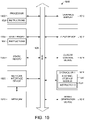
- FIG. 9 illustrates the SRTP key rotation signaling in accordance with example embodiments.
- FIG. 9 focus on a generic crypto-period management over time as shown in FIG. 8 . It shows the details related to a current crypto-period (i) showing also the end of the previous crypto-period (i ⁇ 1) and the beginning of the next crypto-period (i+1): key creation (security apparatus) and fetching (video management system), SRTP MKI packet header format and period of usage of the key by both.
- the method and system splits the video content from a camera into RTP packets and encrypts the payloads of the RTP packets to enable secure transmission.
- Headers of the RTP packets carry at least two copies of encryption keys for use in the decryption of the RTP packets when received after transmission to a video management system.
- the encryption keys at least one is the current encryption key required for encryption in the current crypto period when key rotation is used.
- the key for the next crypto period can be obtained and included as at least one of the keys in the header of the RTP packet. This provides the decryption process with the key in advance of the crypto period in which it is required and avoids decryption delays.
- the encrypted RTP packets are SRTP packets and the in order to be compliant with the SRTP specification, only one key can be contained in the header of each packet. This can be met by providing a single key in the form of a combination of a plurality of keys. The keys can be combined to appear as a single key by simple concatenation or by any other combinatorial method.
- the RTP header includes two keys, which are either two copies of the current key for the current crypto period, or, near the end of the crypto period, the RTP header in the packets is changed to include the current key and the key for the next crypto period.
- the keys inserted in the headers of the RTP packets can be key identifiers used to identify the master key to be used for decryption.
- the key management protocol may exchange a single master key, and all session keys are generated by applying the key derivation function.
- key rotation signaling is performed using an original master key index (MKI) for signaling two key identifiers (KID).
- FIG. 10 is a block diagram illustrating components of a machine 1000 , according to some example embodiments, able to read instructions 1024 from a machine-storage medium 1022 (e.g., a non-transitory machine-storage medium, a machine-readable storage medium, a computer-readable storage medium, or any suitable combination thereof) and perform any one or more of the methodologies discussed herein, in whole or in part.
- a machine-storage medium 1022 e.g., a non-transitory machine-storage medium, a machine-readable storage medium, a computer-readable storage medium, or any suitable combination thereof
- FIG. 1022 e.g., a non-transitory machine-storage medium, a machine-readable storage medium, a computer-readable storage medium, or any suitable combination thereof
- FIG. 10 shows the machine 1000 in the example form of a computer device (e.g., a computer) within which the instructions 1024 (e.g., software, a program, an application, an applet, an app, or other executable code) for causing the machine 1000 to perform any one or more of the methodologies discussed herein may be executed, in whole or in part.
- the machine 1000 may be the edge security apparatus.
- the instructions 1024 can transform the general, non-programmed machine 1000 into a particular machine (e.g., specially configured machine) programmed to carry out the described and illustrated functions in the manner described.
- the machine 1000 operates as a standalone device or may be connected (e.g., networked) to other machines.
- the machine 1000 may be a server computer, a client computer, a personal computer (PC), a tablet computer, a laptop computer, a netbook, a set-top box (e.g. STB), a personal digital assistant (PDA), a cellular telephone, a smartphone, a web appliance, a network router, a network switch, a network bridge, a power adapter, or any machine 1000 capable of executing the instructions 1024 , sequentially or otherwise, that specify actions to be taken by that machine 1000 .
- the term “machine” shall also be taken to include a collection of machines that individually or jointly execute the instructions 1024 to perform any one or more of the methodologies discussed herein.
- the machine 1000 includes a processor 1002 (e.g., a central processing unit (CPU), a graphics processing unit (GPU), a digital signal processor (DSP), an application specific integrated circuit (ASIC), a radio-frequency integrated circuit (RFIC), or any suitable combination thereof), a main memory 1004 , and a static memory 1006 , which are configured to communicate with each other via a bus 1008 .
- the processor 1002 may contain microcircuits that are configurable, temporarily or permanently, by some or all of the instructions 1024 such that the processor 1002 is configurable to perform any one or more of the methodologies described herein, in whole or in part.
- a set of one or more microcircuits of the processor 1002 may be configurable to execute one or more modules (e.g., software modules) described herein.
- the machine 1000 may further include a graphics display 1010 (e.g., a plasma display panel (PDP), a light emitting diode (LED) display, a liquid crystal display (LCD), a projector, a cathode ray tube (CRT), or any other display capable of displaying graphics or video).
- a graphics display 1010 e.g., a plasma display panel (PDP), a light emitting diode (LED) display, a liquid crystal display (LCD), a projector, a cathode ray tube (CRT), or any other display capable of displaying graphics or video).
- PDP plasma display panel
- LED light emitting diode
- LCD liquid crystal display
- CRT cathode ray tube
- the machine 1000 may also include an alphanumeric input device 1012 (e.g., a keyboard or keypad), a cursor control device 1014 (e.g., a mouse, a touchpad, a trackball, a joystick, a motion sensor, an eye tracking device, or other pointing instrument), a storage unit 1016 , a signal generation device 1018 (e.g., a sound card, an amplifier, a speaker, a headphone jack, or any suitable combination thereof), and a network interface device 1020 .
- an alphanumeric input device 1012 e.g., a keyboard or keypad
- a cursor control device 1014 e.g., a mouse, a touchpad, a trackball, a joystick, a motion sensor, an eye tracking device, or other pointing instrument
- a storage unit 1016 e.g., a storage unit 1016 , a signal generation device 1018 (e.g., a sound card, an amplifier, a speaker,
- the storage unit 1016 includes the machine-storage medium 1022 (e.g., a tangible machine-readable storage medium) on which are stored the instructions 1024 embodying any one or more of the methodologies or functions described herein.
- the instructions 1024 may also reside, completely or at least partially, within the main memory 1004 , within the processor 1002 (e.g., within the processor's cache memory), or both, before or during execution thereof by the machine 1000 . Accordingly, the main memory 1004 and the processor 1002 may be considered machine-storage media 1022 (e.g., tangible and non-transitory machine-storage media).
- the machine 1000 may be a portable computing device and have one or more additional input components (e.g., sensors or gauges).
- additional input components e.g., sensors or gauges.
- input components include an image input component (e.g., one or more cameras), an audio input component (e.g., a microphone), a direction input component (e.g., a compass), a location input component (e.g., a global positioning system (GPS) receiver), an orientation component (e.g., a gyroscope), a motion detection component (e.g., one or more accelerometers), an altitude detection component (e.g., an altimeter), and a gas detection component (e.g., a gas sensor).
- Inputs harvested by any one or more of these input components may be accessible and available for use by any of the modules described herein.
- the various memories (i.e., 1004 , 1006 , and/or memory of the processor(s) 1002 ) and/or storage unit 1016 may store one or more sets of instructions and data structures (e.g., software) 1024 embodying or utilized by any one or more of the methodologies or functions described herein. These instructions, when executed by processor(s) 1002 cause various operations to implement the disclosed embodiments.
- machine-storage medium As used herein, the terms “machine-storage medium,” “device-storage medium,” “computer-storage medium” (referred to collectively as “machine-storage medium 1022 ”) mean the same thing and may be used interchangeably in this disclosure.
- the terms refer to a single or multiple storage devices and/or media (e.g., a centralized or distributed database, and/or associated caches and servers) that store executable instructions and/or data, as well as cloud-based storage systems or storage networks that include multiple storage apparatus or devices.
- the terms shall accordingly be taken to include, but not be limited to, solid-state memories, and optical and magnetic media, including memory internal or external to processors.
- machine-storage media, computer-storage media, and/or device-storage media 1022 include non-volatile memory, including by way of example semiconductor memory devices, e.g., erasable programmable read-only memory (EPROM), electrically erasable programmable read-only memory (EEPROM), FPGA, and flash memory devices; magnetic disks such as internal hard disks and removable disks; magneto-optical disks; and CD-ROM and DVD-ROM disks.
- EPROM erasable programmable read-only memory
- EEPROM electrically erasable programmable read-only memory
- FPGA field-programmable read-only memory
- flash memory devices e.g., erasable programmable read-only memory (EPROM), electrically erasable programmable read-only memory (EEPROM), FPGA, and flash memory devices
- magnetic disks such as internal hard disks and removable disks
- magneto-optical disks and CD-ROM and DVD-ROM disks.
- signal medium or “transmission medium” shall be taken to include any form of modulated data signal, carrier wave, and so forth.
- modulated data signal means a signal that has one or more of its characteristics set or changed in such a matter as to encode information in the signal.
- machine-readable medium means the same thing and may be used interchangeably in this disclosure.
- the terms are defined to include both machine-storage media and signal media.
- the terms include both storage devices/media and carrier waves/modulated data signals.
- the instructions 1024 may further be transmitted or received over a communications network 1026 using a transmission medium via the network interface device 1020 and utilizing any one of a number of well-known transfer protocols (e.g., HTTP).
- Examples of communication networks 1026 include a local area network (LAN), a wide area network (WAN), the Internet, mobile telephone networks, plain old telephone service (POTS) networks, and wireless data networks (e.g., WiFi, LTE, and WiMAX networks).
- POTS plain old telephone service
- wireless data networks e.g., WiFi, LTE, and WiMAX networks.
- transmission medium shall be taken to include any intangible medium that is capable of storing, encoding, or carrying instructions 1024 for execution by the machine 1000 , and includes digital or analog communications signals or other intangible medium to facilitate communication of such software.
- Modules may constitute either software modules (e.g., code embodied on a machine-storage medium 1022 or in a transmission signal) or hardware modules.
- a “hardware module” is a tangible unit capable of performing certain operations and may be configured or arranged in a certain physical manner.
- one or more computer systems e.g., a standalone computer system, a client computer system, or a server computer system
- one or more hardware modules of a computer system e.g., a processor 1002 or a group of processors 1002
- software e.g., an application or application portion
- a hardware module may be implemented mechanically, electronically, or any suitable combination thereof.
- a hardware module may include dedicated circuitry or logic that is permanently configured to perform certain operations.
- a hardware module may be a special-purpose processor, such as a field-programmable gate array (FPGA) or an ASIC.
- a hardware module may also include programmable logic or circuitry that is temporarily configured by software to perform certain operations.
- a hardware module may include software encompassed within a general-purpose processor or other programmable processor. It will be appreciated that the decision to implement a hardware module mechanically, in dedicated and permanently configured circuitry, or in temporarily configured circuitry (e.g., configured by software) may be driven by cost and time considerations.
- hardware module should be understood to encompass a tangible entity, be that an entity that is physically constructed, permanently configured (e.g., hardwired), or temporarily configured (e.g., programmed) to operate in a certain manner or to perform certain operations described herein.
- “hardware-implemented module” refers to a hardware module. Considering embodiments in which hardware modules are temporarily configured (e.g., programmed), each of the hardware modules need not be configured or instantiated at any one instance in time. For example, where a hardware module comprises a general-purpose processor configured by software to become a special-purpose processor, the general-purpose processor may be configured as respectively different special-purpose processors (e.g., comprising different hardware modules) at different times. Software may accordingly configure a processor, for example, to constitute a particular hardware module at one instance of time and to constitute a different hardware module at a different instance of time.
- processors may be temporarily configured (e.g., by software) or permanently configured to perform the relevant operations. Whether temporarily or permanently configured, such processors may constitute processor-implemented modules that operate to perform one or more operations or functions described herein.
- processor-implemented module refers to a hardware module implemented using one or more processors.
- the methods described herein may be at least partially processor-implemented, a processor being an example of hardware.
- processors or processor-implemented modules may be performed by one or more processors or processor-implemented modules.
- Example 1 is a method for securing a deployed camera.
- the method comprises accessing, by a security apparatus coupled to a camera, video content from the coupled camera; accessing, by a security apparatus coupled to a camera, video content from the coupled camera; splitting, by a security apparatus, the video content within a plurality of RTP packets; encrypting, by a security apparatus, payloads of the RTP packets; embedding, by a security apparatus, in a header of the encrypted RTP packets, at least two key identifications for decryption of the encrypted RTP packets; and transmitting, by a security apparatus, the plurality of RTP packets over a network to a video management system.
- the video content is packaged in a CMAF fragments.
- example 3 including the subject matter of examples 1-2, optionally the header of the encrypted RTP packets is conformed to the SRTP standard
- the encrypting the video content further comprises encrypting the RTP packets with (MKI12, K1) in response to entering pre-delivery windows.
- the encrypting the video content further comprises in response to entering a next crypto-period, requesting a further key from the key server (K3); encrypting the RTP packets with (MKI22, K2); and receiving the further key (K3, Kid3).
- the apparatus is coupled to the deployed camera by connecting the apparatus behind the camera.
- example 9 can optionally include, at the video management system, receiving, over the network, the CMAF fragments within the plurality of RTP packets; identifying the CMAF fragments in the RTP packets; and rendering video from the CMAF fragments.
- Example 10 is a system to secure a deployed camera.
- the system includes one or more hardware processors and a storage device storing instructions, that when executed by the one or more hardware processors, cause the one or more hardware processors to carry out the method of any one of examples 1 to 9.
- Example 11 is a machine-storage medium for securing a deployed camera.
- the machine-storage medium carries machine readable instructions, which when implemented by at least one processor of the machine, causes the machine to carry out the method of any one of examples 1 to 9.
- Example 12 is a signal medium for securing a deployed camera.
- the signal medium carries machine readable instructions, which when implemented by at least one processor of the machine, causes the machine to carry out the method of any one of examples 1 to 9.
- inventive subject matter has been described with reference to specific example embodiments, various modifications and changes may be made to these embodiments without departing from the broader scope of embodiments of the present invention.
- various embodiments or features thereof may be mixed and matched or made optional by a person of ordinary skill in the art.
- Such embodiments of the inventive subject matter may be referred to herein, individually or collectively, by the term “invention” merely for convenience and without intending to voluntarily limit the scope of this application to any single invention or inventive concept if more than one is, in fact, disclosed.
Landscapes
- Engineering & Computer Science (AREA)
- Computer Security & Cryptography (AREA)
- Computer Networks & Wireless Communication (AREA)
- Signal Processing (AREA)
- Computer Hardware Design (AREA)
- Computing Systems (AREA)
- General Engineering & Computer Science (AREA)
- Two-Way Televisions, Distribution Of Moving Picture Or The Like (AREA)
- Mobile Radio Communication Systems (AREA)
- Alarm Systems (AREA)
Abstract
Description
-
- S=1: start of fragmented chunk (else S=0)
- E=1: end of fragmented chunk (else E=0)
- Type=FU-A=28
- Marker bit=1 for RTP packet containing last fragment of chunk.
-
- Startup
- When a new RTP session is created, the proxy asks asynchronously for 1 key from the key server:
- When first key (K1, Kid1) arrives, the proxy sets a master key K1 to srtpWrapper with MKI11=(Kid1∥Kid1)
- Start crypto-period
- The proxy asks for a next key (K2)
- RTP packets can be encrypted with (MKI11, K1)
- When next key (K2, Kid2) arrives:
- The proxy sets again a master key K1 to srtpWrapper with MKI12=(Kid1∥Kid2)
- The proxy sets master key K2 to srtpWrapper with MKI22=(Kid2∥Kid2)
- At this stage, srtpWrapper table contains (MKI11, K1), (MKI12, K1), and (MKI22, K2)
- When entering into pre-delivery windows:
- RTP packets are encrypted with (MKI12, K1)
- When entering into next crypto-period:
- The proxy asks asynchronously for a next key from the key server (K3)
- RTP packets are encrypted with (MKI22, K2)
- When next key (K3, Kid3) arrives:
- The proxy sets again a master key K2 to srtpWrapper with MKI23=(Kid2∥Kid3)
- At this stage, srtpWrapper table contains (MKI23, K2), (MKI12, K1), and (MKI22, K2)
- The proxy sets master key K3 to srtpWrapper with MKI33=(Kid3∥Kid3)
- At this stage, srtpWrapper table contains (MKI23, K2), (MKI33, K3) and (MKI22, K2)
- The proxy sets again a master key K2 to srtpWrapper with MKI23=(Kid2∥Kid3)
- It will be well understood that this embodiment is not a limited example and key signaling as proposed in RTP can be used independently of CMAF in the payload of RTP. Thus
- MKI11=f(Kid1,Kid1)
- MKI12=f(Kid1,Kid2)
- MKI22=f(Kid1,Kid2)
- Other forms of the function f(Kid) can be used, rather than a concatenation function of two input parameters in their order Kidn
∥Kidn+ 1.
- Startup
Claims (19)
Priority Applications (1)
| Application Number | Priority Date | Filing Date | Title |
|---|---|---|---|
| US16/956,180 US11546151B2 (en) | 2017-12-20 | 2018-12-20 | System for securing deployed security cameras |
Applications Claiming Priority (6)
| Application Number | Priority Date | Filing Date | Title |
|---|---|---|---|
| US201762608556P | 2017-12-20 | 2017-12-20 | |
| EP18305014 | 2018-01-09 | ||
| EP18305014.5 | 2018-01-09 | ||
| EP18305014 | 2018-01-09 | ||
| PCT/EP2018/086402 WO2019122242A1 (en) | 2017-12-20 | 2018-12-20 | System for securing deployed security cameras |
| US16/956,180 US11546151B2 (en) | 2017-12-20 | 2018-12-20 | System for securing deployed security cameras |
Publications (2)
| Publication Number | Publication Date |
|---|---|
| US20200344053A1 US20200344053A1 (en) | 2020-10-29 |
| US11546151B2 true US11546151B2 (en) | 2023-01-03 |
Family
ID=64744739
Family Applications (1)
| Application Number | Title | Priority Date | Filing Date |
|---|---|---|---|
| US16/956,180 Active 2039-06-24 US11546151B2 (en) | 2017-12-20 | 2018-12-20 | System for securing deployed security cameras |
Country Status (4)
| Country | Link |
|---|---|
| US (1) | US11546151B2 (en) |
| EP (1) | EP3688959B1 (en) |
| ES (1) | ES2935614T3 (en) |
| WO (1) | WO2019122242A1 (en) |
Families Citing this family (4)
| Publication number | Priority date | Publication date | Assignee | Title |
|---|---|---|---|---|
| US11546151B2 (en) | 2017-12-20 | 2023-01-03 | Nagravision S.A. | System for securing deployed security cameras |
| TWI868416B (en) * | 2021-12-29 | 2025-01-01 | 新唐科技股份有限公司 | Method and device for protecting and managing key |
| CN116097621B (en) * | 2022-05-06 | 2025-07-04 | 北京小米移动软件有限公司 | Data interaction method, device, electronic device and storage medium |
| US20240056430A1 (en) * | 2022-08-12 | 2024-02-15 | Meta Platforms, Inc. | End-to-end encryption for video conference calls |
Citations (7)
| Publication number | Priority date | Publication date | Assignee | Title |
|---|---|---|---|---|
| US20030093694A1 (en) * | 2001-11-15 | 2003-05-15 | General Instrument Corporation | Key management protocol and authentication system for secure internet protocol rights management architecture |
| US20050002525A1 (en) * | 2003-07-03 | 2005-01-06 | Microsoft Corporation | RTP payload format |
| US20070033391A1 (en) * | 2005-08-02 | 2007-02-08 | Mitsubishi Denki Kabushiki Kaisha | Data distribution apparatus and data communications system |
| US20090141894A1 (en) * | 2007-12-04 | 2009-06-04 | Kuldip Sahdra | Usb video card and dongle device with video encoding and methods for use therewith |
| US20130223622A1 (en) | 2012-02-27 | 2013-08-29 | Motorola Solutions, Inc. | Method and device for rekeying in a radio network link layer encryption system |
| US20170171611A1 (en) * | 2015-12-15 | 2017-06-15 | Telefonaktiebolaget Lm Ericsson (Publ) | System and method for facilitating fast channel change |
| WO2019122242A1 (en) | 2017-12-20 | 2019-06-27 | Nagravision S.A | System for securing deployed security cameras |
-
2018
- 2018-12-20 US US16/956,180 patent/US11546151B2/en active Active
- 2018-12-20 WO PCT/EP2018/086402 patent/WO2019122242A1/en not_active Ceased
- 2018-12-20 ES ES18822102T patent/ES2935614T3/en active Active
- 2018-12-20 EP EP18822102.2A patent/EP3688959B1/en active Active
Patent Citations (7)
| Publication number | Priority date | Publication date | Assignee | Title |
|---|---|---|---|---|
| US20030093694A1 (en) * | 2001-11-15 | 2003-05-15 | General Instrument Corporation | Key management protocol and authentication system for secure internet protocol rights management architecture |
| US20050002525A1 (en) * | 2003-07-03 | 2005-01-06 | Microsoft Corporation | RTP payload format |
| US20070033391A1 (en) * | 2005-08-02 | 2007-02-08 | Mitsubishi Denki Kabushiki Kaisha | Data distribution apparatus and data communications system |
| US20090141894A1 (en) * | 2007-12-04 | 2009-06-04 | Kuldip Sahdra | Usb video card and dongle device with video encoding and methods for use therewith |
| US20130223622A1 (en) | 2012-02-27 | 2013-08-29 | Motorola Solutions, Inc. | Method and device for rekeying in a radio network link layer encryption system |
| US20170171611A1 (en) * | 2015-12-15 | 2017-06-15 | Telefonaktiebolaget Lm Ericsson (Publ) | System and method for facilitating fast channel change |
| WO2019122242A1 (en) | 2017-12-20 | 2019-06-27 | Nagravision S.A | System for securing deployed security cameras |
Non-Patent Citations (13)
Also Published As
| Publication number | Publication date |
|---|---|
| ES2935614T3 (en) | 2023-03-08 |
| US20200344053A1 (en) | 2020-10-29 |
| WO2019122242A1 (en) | 2019-06-27 |
| EP3688959B1 (en) | 2022-11-16 |
| EP3688959A1 (en) | 2020-08-05 |
Similar Documents
| Publication | Publication Date | Title |
|---|---|---|
| US20240289469A1 (en) | System and method for enhanced data protection | |
| US11432039B2 (en) | Systems and methods for data processing, storage, and retrieval from a server | |
| CN108989848B (en) | A kind of acquisition method and management system of video resource file | |
| US10581599B2 (en) | Cloud storage method and system | |
| US9219709B2 (en) | Multi-wrapped virtual private network | |
| US11546151B2 (en) | System for securing deployed security cameras | |
| US20180063105A1 (en) | Management of enciphered data sharing | |
| CN107659829A (en) | A kind of method and system of video-encryption | |
| US20130185569A1 (en) | Data protection system and method based on cloud storage | |
| US8281122B2 (en) | Generation and/or reception, at least in part, of packet including encrypted payload | |
| US20180278414A1 (en) | Encrypted data sharing with a hierarchical key structure | |
| US20170244685A1 (en) | Multipath demultiplexed network encryption | |
| CN106817358A (en) | The encryption and decryption method and equipment of a kind of user resources | |
| JP2009532813A (en) | File decryption interface | |
| CN116633582A (en) | Secure communication method, device, electronic device and storage medium | |
| US9825920B1 (en) | Systems and methods for multi-function and multi-purpose cryptography | |
| WO2016202089A1 (en) | Method, apparatus, and system for encrypting data of remote storage device | |
| US20170331798A1 (en) | Encrypted-bypass webrtc-based voice and/or video communication method | |
| CN110912941A (en) | Transmission processing method and device for multicast data | |
| KR101457455B1 (en) | Apparatus and method for data security in cloud networks | |
| US9178855B1 (en) | Systems and methods for multi-function and multi-purpose cryptography | |
| CN111431846B (en) | Method, device and system for data transmission | |
| US10873773B2 (en) | Countermeasure for cryptographic cribs | |
| US9189638B1 (en) | Systems and methods for multi-function and multi-purpose cryptography | |
| JP2023535011A (en) | quantum streaming |
Legal Events
| Date | Code | Title | Description |
|---|---|---|---|
| FEPP | Fee payment procedure |
Free format text: ENTITY STATUS SET TO UNDISCOUNTED (ORIGINAL EVENT CODE: BIG.); ENTITY STATUS OF PATENT OWNER: LARGE ENTITY |
|
| STPP | Information on status: patent application and granting procedure in general |
Free format text: DOCKETED NEW CASE - READY FOR EXAMINATION |
|
| STPP | Information on status: patent application and granting procedure in general |
Free format text: NON FINAL ACTION MAILED |
|
| STPP | Information on status: patent application and granting procedure in general |
Free format text: NOTICE OF ALLOWANCE MAILED -- APPLICATION RECEIVED IN OFFICE OF PUBLICATIONS |
|
| AS | Assignment |
Owner name: NAGRAVISION S.A., SWITZERLAND Free format text: ASSIGNMENT OF ASSIGNORS INTEREST;ASSIGNOR:TRAN, MINH-SON;REEL/FRAME:061890/0349 Effective date: 20180624 Owner name: NAGRAVISION S.A., SWITZERLAND Free format text: ASSIGNMENT OF ASSIGNORS INTEREST;ASSIGNORS:ANGEL, MICHEL;LE BERRE, PHILIPPE;RETAUREAU, HERVE;SIGNING DATES FROM 20011218 TO 20200827;REEL/FRAME:061890/0142 |
|
| STPP | Information on status: patent application and granting procedure in general |
Free format text: AWAITING TC RESP, ISSUE FEE PAYMENT VERIFIED |
|
| STCF | Information on status: patent grant |
Free format text: PATENTED CASE |